Embed Size (px)
Citation preview
THOROUGH ANALYSIS ! DEPENDABLE ADVICE !
GEOTECHNICAL SITE INVESTIGATION
FOR
THE PROPOSED 72 LOT NORTHBROOK SUBDIVISION
AT
52 NORTH ROAD
CLEVEDON
FOR
NORTHBROOK LIMITED
GEOTECHNICAL REPORT FOR PROPOSED 72 LOT
RESIDENTIAL SUBDIVISION
Ref No. 5758 24 February 2017
GEOTEK SERVICES LIMITED1/55 Druces Road, Manukau Central PO Box 217-172, Botany Junction, Auckland 2164Phone (64-9) 261-0169 Facsimile (64-9) 261-0548 E-mail [email protected]
Proposed 72 Lot Subdivision Ref: 5758 52 North Road Clevedon
Geotek Services Limited 24 February 2017
THOROUGH ANALYSIS ! DEPENDABLE ADVICE !
3
1. Introduction This geotechnical site investigation report has been undertaken at 52 North Road for our clients, Northbrook Limited. A scheme plan entitled “Scheme Plan 52 North Road Clevedon” has been supplied to us by Yeomans Survey Solutions Limited dated January 2017 (reference 7691/SC), which shows that the subject site is to be subdivided into 72 residential lots, ranging in area from 204m2 up to 6660m2. This scheme has evolved significantly throughout our involvement with the project. We can confirm that we have been providing ongoing advice, throughout our investigation process, to the Civil Engineering design team at Crang Civil Limited, with our initial investigations having commenced in
June 2016. The primary purpose of our geotechnical investigation was to investigate the suitability of site soils for the safe support of future residential buildings, as well as to carefully assess the level of Geotechnical Risk posed to such buildings in terms of land instability and, if deemed necessary, provide recommendations to reduce such risk which include, but are not limited to, earthworks, subsoil drainage and building setbacks from “at-risk” slopes. The approach adopted herein has been to identify “Designated Building Areas” (DBA’s) within each proposed lot, primarily positioned in areas evaluated to be within manageable risk levels of slope instability. Furthermore, the evaluation is broadly in terms of the requirements of NZS3604:2011, for the construction of light-weight residential buildings. This is not to preclude building development outside of the designated building areas or the limitations of NZS3604, but rather, to require additional geotechnical evaluation, which will likely require further investigation as well as approval by Council. Such an assessment must be undertaken by a suitably experienced Geo-Professional, who is familiar with the content of both this report, as well as an anticipated future Geotechnical Completion Report, which will be prepared once the proposed subdivision development has been completed. Please note, the DBA’s are purely geotechnical areas and do not take into account planning requirements such as yard setbacks and height to boundary requirements. We have also been supplied with engineering drawings by Crang Civil Limited, the majority of which relate to the civil works including bulk earthworks, drainage and road formation, (reference 1169, dated 17 February 2017). Any variations of these development proposals forming the basis of the geotechnical assessment herein should be referred back to us for further evaluation.
Proposed 72 Lot Subdivision Ref: 5758 52 North Road Clevedon
Geotek Services Limited 24 February 2017
THOROUGH ANALYSIS ! DEPENDABLE ADVICE !
4
We anticipate that this report is to be submitted to Council in support of a Resource Consent application for subdivision and earthworks approval, and should not be used to support any Building Consent application/s, with the exception of the proposed timber pole retaining walls as described herein.
2. Limitations Except to the extent that Council may rely on it in order to issue an associated Consent, this report has been commissioned solely for the benefit of our clients, Northbrook Limited, specifically in relation to the project as described herein, and to the limits of our engagement. Any variations from the development proposals as
described herein as forming the basis of our appraisal should be referred back to us for further evaluation. Copyright of Intellectual Property remains with Geotek Services Limited, and this report may NOT be used by any other entity, or for any other proposals, without our written consent. Therefore, no liability is accepted by this firm or any of its directors, servants or agents, in respect of any other geotechnical aspects of this site, nor for its use by any other person or entity, and any other person or entity who relies upon any information contained herein does so entirely at their own risk, with the exception that the local Territorial Authority may rely on it to the extent of its appropriateness, conditions and limitations, when issuing the subject consent. Where other parties may wish to rely on it, whether for the same or different proposals, this permission may be extended, subject to our satisfactory review of their interpretation of the report. Although this report may be submitted to a local authority in connection with an application for a consent, permission, approval, or pursuant to any other requirement of law, this disclaimer shall still apply and require all other parties to use due diligence where necessary, and does not remove the necessity for the normal inspection of site conditions and the design of foundations as would be made under all normal circumstances.
3. Investigation Methodology
This investigation was undertaken generally in accordance with the standards set out in section 2 “Earthworks & Geotechnical Requirements” of NZS4404:2010 “Land Development and Subdivision Infrastructure” as well as section 2 “Earthworks and Geotechnical Requirements” of the Auckland Council Code of Practice for Land Development & Subdivision (Version 1.6 dated 24 September 2013). The initial stage of investigation involved a desk study where we reviewed information available to us on
surrounding sites, followed by a walkover assessment undertaken by a suitably experienced Engineering Geologist. The primary aim of this stage was to identify and interpret the geomorphology, as well as
Proposed 72 Lot Subdivision Ref: 5758 52 North Road Clevedon
Geotek Services Limited 24 February 2017
THOROUGH ANALYSIS ! DEPENDABLE ADVICE !
5
establish qualitatively the risk of slope instabilities. This work has included inspection of site features, gully slopes, gully inverts, and both recent and historical aerial photographs. The second stage of the investigation involved intrusive ground investigation, which comprised hand augering of 52 (no.) 50mm diameter boreholes, to depths of up to 5 metres across the site. As each excavation progressed, careful inspections were made of the materials observed, and soil shear strength and remould tests were performed insitu, at selected depths, using a hand-held shear vane. The materials identified are described in detail on the appended records, together with the results of the various tests undertaken, plus the groundwater conditions as determined during our time on site. Finally, all the above information has been collated, with cross sections developed showing the existing and proposed ground profiles, as well as the underlying inferred stratigraphic horizons, so that numerical slope stability modeling could be undertaken under both static and pseudo-seismic conditions, resulting in a list of Conclusions and Recommendations in the final section of this report, relating to the creation of lots with suitably safe and stable Designated Building Areas (DBA).
4. Geology
Reference to the Institute of Geological & Nuclear Sciences, Geological Map 3 of the Auckland Area, 1:250,000, indicates that the subject site is typical of a significant part of the low lying Auckland area, in that it is underlain by sediments of the Tauranga Group sedimentary lithology (Pliocene to Holocene Epoch). According to the book, “Geology of the Auckland Area”, compiled by S.W. Edbrooke and published by the Institute of Geological & Nuclear Sciences in 2001, tectonic uplift, mainly westward tilting, during late Miocene times, produced a significant change in the sedimentary depositional environment of the Auckland region with deep erosion and mainly terrestrial, rather than marine deposition. Fluctuating sea levels brought on by the Ice Ages, brought many changes to the ephemeral islands and channels of the Auckland region. Tauranga Group sediments are heterogeneous, including gravels, sands, silts, muds and peats of fluvial, lacustrine and distal ignimbritic origin (both airborne and waterborne pumiceous materials). As a result, these deposits can often contain interbedded layers and/or lenses of muddy peats within the predominantly silty and clayey alluvium. The most recent deposits (geologically speaking) underlying the site, are the Pleistocene & Holocene Epoch
deposits of undifferentiated alluvium, consisting of unconsolidated soft muds, sands, gravels and thin peaty lenses, are commonly encountered above the older more consolidated and generally pumiceous materials.
Proposed 72 Lot Subdivision Ref: 5758 52 North Road Clevedon
Geotek Services Limited 24 February 2017
THOROUGH ANALYSIS ! DEPENDABLE ADVICE !
6
Fluctuating sea levels eventually flooded the large valleys to form the Waitemata and Manukau harbours. In our experience gathered on sites further to the north along North Road, these alluvial “drift” deposits are more than likely unconformably overlying Waipapa Group materials, typically found in south-eastern parts of Auckland such as the Hunua Ranges and the islands of the Hauraki Gulf. These basement rocks are the oldest found in the Auckland region and constitute the basement materials that underlie the eastern half of Auckland, dating from the Late Triassic Period, over 200 million years ago, up until the Early Cretaceous Period, around 140 million years ago. Waipapa Group materials generally consist of thin to massive thicknesses of poorly bedded, fine-grained
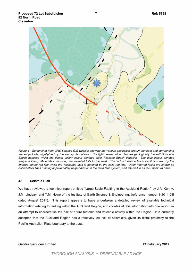
sandstone and argillite (clay-fine matrix) termed “Greywacke”. In its unweathered to slightly weathered state it is characterized by its strength, dark grey-blue colour with closely spaced fracturing (6-600 mm) and shearing, with many veins (up to 50 mm wide) composed of quartz, calcite, prehnite, chlorite, and zeolites. Little is known about the complex structure of this group, as many original bedding structures and rock boundaries are hard to discern due to the intense deformation of the rock mass. The rock originated as sediments on the floor of the ocean, apparently in deep water off the coast of the ancient southern supercontinent, Gondwanaland. These sediments, deposited in a deep sea trench were subject to intense pressure and heat as they were consumed in the subduction zone at the boundary of the continental plate. At the close of the Jurassic period, approximately 130 million years ago, these deformed, shattered and partially metamorphosed rocks were uplifted out of the ocean to form a high mountain range. In terms of the underlying structural geology, the site is considered to be in reasonably close proximity to a confluence of fault systems however, the exact location and alignment of the faults is not known with certainty and we understand that they have been determined by topographical interpretation. We do point out that there do not appear to be faults identified which directly underlie the subject site (Refer Figure 1 below.) Taitaia Stream, which runs along the western boundary of the site, is inferred to be running along a fault lineament (named the Papakura Fault) which has most likely been in-filled with sediment. We discuss the faults and the associated Seismic Risk in the following section.
Proposed 72 Lot Subdivision Ref: 5758 52 North Road Clevedon
Geotek Services Limited 24 February 2017
THOROUGH ANALYSIS ! DEPENDABLE ADVICE !
7
Figure 1 - Screenshot from GNS Science GIS website showing the various geological stratum beneath and surrounding the subject site, highlighted by the star symbol above. The light cream colour denotes geologically “recent” Holocene Epoch deposits whilst the darker yellow colour denotes older Pliocene Epoch deposits. The blue colour denotes Waipapa Group Materials comprising the elevated hills to the west. The 'active" Wairoa North Fault is shown by the inferred dotted red line whilst the Waikopua fault is denoted by the solid red line. Other inferred faults are shown as dotted black lines running approximately perpendicular to the main fault system, and referred to as the Papakura Fault.
4.1 Seismic Risk We have reviewed a technical report entitled “Large-Scale Faulting in the Auckland Region” by J.A. Kenny,
J.M. Lindsay, and T.M. Howe of the Institute of Earth Science & Engineering, (reference number 1-2011.04l dated August 2011). This report appears to have undertaken a detailed review of available technical information relating to faulting within the Auckland Region, and collates all this information into one report, in an attempt to characterise the risk of future tectonic and volcanic activity within the Region. It is currently accepted that the Auckland Region has a relatively low-risk of seismicity, given its distal proximity to the Pacific-Australian Plate boundary to the east.
Proposed 72 Lot Subdivision Ref: 5758 52 North Road Clevedon
Geotek Services Limited 24 February 2017
THOROUGH ANALYSIS ! DEPENDABLE ADVICE !
8
The point where the Wairoa North Fault changes to the Waikopua Fault is unknown, and arguably might be the same fault. It is our understanding that the basis for the Wairoa North Fault having been active in “recent” times is based on an unpublished Masters Thesis dating from 1999. It should be noted that this is the only fault considered to be “probably” active, in the Auckland Region. We further understand that Watercare Services Limited have engaged consultants over the last decade or so to undertake investigation and assessment of the Wairoa North Fault, and its potential impact on critical infrastructure assets. We have been unable to procure this information at the time of writing this report, however, we found a brief mention in an ARC newsletter dating from October 2003 (“Hazardous Times” Vol. 7 No. 2):
“This investigation determined that the Wairoa North Fault has not been active in the last 16-24 kyrs, however it has been active more recently than 80 +/- 15 kyrs. Minimum and maximum recurrence intervals of 13.6 ka and 42.9 ka respectively have been estimated.”
From further reading of the technical report entitled “Large-Scale Faulting in the Auckland Region”, it appears that, from geophysical surveys undertaken in 1977, the total throw of the Waikopua Fault is thought to be in the order of 350 metres, but it is also generally accepted that such faults may have been active at several different times, spanning millions of years. The period of “block-faulting” which best describes the pattern of
lineaments identified across the elevated topography of Auckland, commenced around 15 million years ago, when the Waitemata Basin was uplifted and eroded down to a peneplain surface, as well as being subjected to NW-SE then NE-SW extensional forces. The peneplain surface is still considered to be identifiable across some parts of Auckland, although towards the eastern Ranges of Hunua, the surface has been uplifted and completely eroded away. The most recent “confirmed” fault movement dates to 340,000 years ago, which was determined from a relatively minor displacement of tephra in an outcrop in Beachlands. It is also generally considered that major faulting had largely abated around 1.5 million years ago. To date, there have been only rare instances where fault-related offsets, have been identified in Pleistocene sediments.
5. Site Description The subject property, legally described as Lot 1 DP169033 and identified as number 52, is situated on the north-western side of North Road, in the rural-residential suburb of Clevedon. The property encompasses just under 9 hectares, comprising predominantly unkempt pasture, as well as lower-lying streams and flood plains. There are various, mostly isolated trees scattered across the site, with the exception of a stand surrounding the existing farm house and associated ancillary buildings and structures along the elevated south-west boundary. There are also several trees, which we understand are protected, along an exposed steep to very steep-sided gully bank adjacent to North Road. The property is accessed from its south-western boundary via. Mark Williams Place, a cul-de-sac which itself forms an intersection with North Road.
Proposed 72 Lot Subdivision Ref: 5758 52 North Road Clevedon
Geotek Services Limited 24 February 2017
THOROUGH ANALYSIS ! DEPENDABLE ADVICE !
9
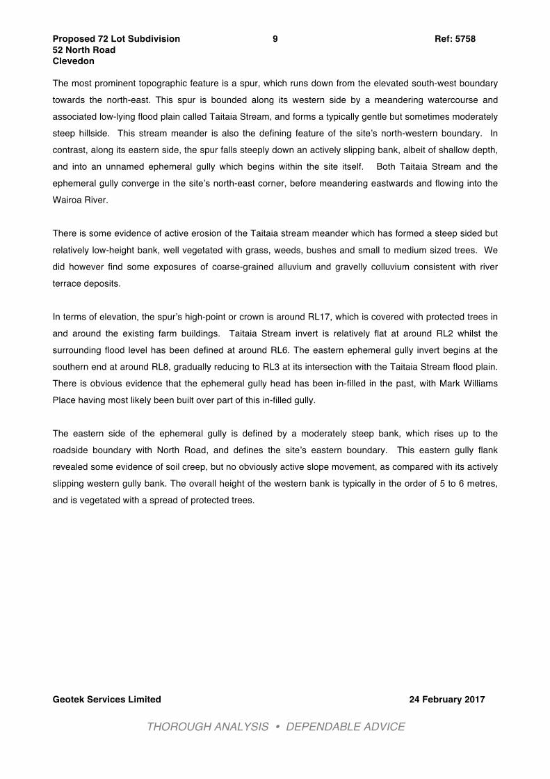
The most prominent topographic feature is a spur, which runs down from the elevated south-west boundary towards the north-east. This spur is bounded along its western side by a meandering watercourse and associated low-lying flood plain called Taitaia Stream, and forms a typically gentle but sometimes moderately steep hillside. This stream meander is also the defining feature of the site’s north-western boundary. In contrast, along its eastern side, the spur falls steeply down an actively slipping bank, albeit of shallow depth, and into an unnamed ephemeral gully which begins within the site itself. Both Taitaia Stream and the ephemeral gully converge in the site’s north-east corner, before meandering eastwards and flowing into the Wairoa River. There is some evidence of active erosion of the Taitaia stream meander which has formed a steep sided but
relatively low-height bank, well vegetated with grass, weeds, bushes and small to medium sized trees. We did however find some exposures of coarse-grained alluvium and gravelly colluvium consistent with river terrace deposits. In terms of elevation, the spur’s high-point or crown is around RL17, which is covered with protected trees in and around the existing farm buildings. Taitaia Stream invert is relatively flat at around RL2 whilst the surrounding flood level has been defined at around RL6. The eastern ephemeral gully invert begins at the southern end at around RL8, gradually reducing to RL3 at its intersection with the Taitaia Stream flood plain. There is obvious evidence that the ephemeral gully head has been in-filled in the past, with Mark Williams Place having most likely been built over part of this in-filled gully. The eastern side of the ephemeral gully is defined by a moderately steep bank, which rises up to the roadside boundary with North Road, and defines the site’s eastern boundary. This eastern gully flank revealed some evidence of soil creep, but no obviously active slope movement, as compared with its actively slipping western gully bank. The overall height of the western bank is typically in the order of 5 to 6 metres, and is vegetated with a spread of protected trees.
Proposed 72 Lot Subdivision Ref: 5758 52 North Road Clevedon
Geotek Services Limited 24 February 2017
THOROUGH ANALYSIS ! DEPENDABLE ADVICE !
10
Figure 2: Council GIS Aerial Photo showing the subject property boundaries in blue. Contours in orange
at 0.5m intervals. Note: North is up the page.
Proposed 72 Lot Subdivision Ref: 5758 52 North Road Clevedon
Geotek Services Limited 24 February 2017
THOROUGH ANALYSIS ! DEPENDABLE ADVICE !
11
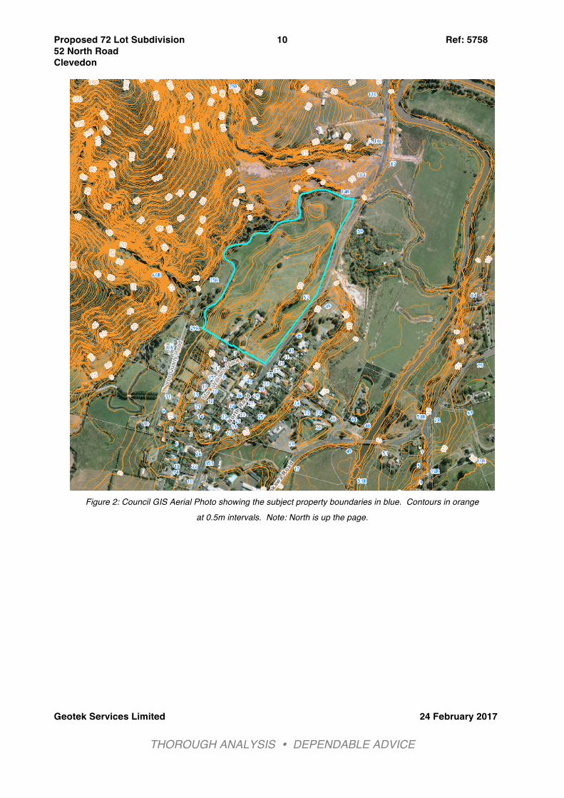
6. Aerial Photograph Review In an effort to identify if there has been any identifiable slope movement over the last 50 or so years, we have reviewed a historical aerial photograph of the site dating from 1960, and compared this with a more recent aerial photograph dating from 2006. In addition we reviewed aerial photographs on Council’s GIS database Alggi, dating from 2003 through to 2010. We can see that the site was already being used as pasture in 1960, and there is no obvious evidence of
slope movement having occurred since that time. The only visible changes to the site itself comprise a gradual reduction in the density of the trees along the steep eastern ephemeral gully bank.
Figure 3 - Aerial photo of the site and its surrounds dating from 1960. Source: NZ Aerial Mapping.
Proposed 72 Lot Subdivision Ref: 5758 52 North Road Clevedon
Geotek Services Limited 24 February 2017
THOROUGH ANALYSIS ! DEPENDABLE ADVICE !
12
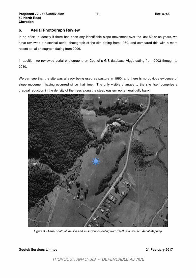
Figure 4 - Aerial photo of the site and its surrounds dating from 2010. Source: Auckland Council GIS. 7. Subdivision Development Proposals The existing farmhouse has already been demolished and we understand that the remaining ancillary structures will also be removed. The proposed development scheme will comprise the formation of a public road intersecting Mark Williams Place, at roughly the same location as the existing site entrance. The public road or Road 1 will be a cul-de-sac, in turn providing access to 5 (no.) private roads or Joint Owned Accessway Lots (JOAL) with two to the north-west, one to the north, and two to the east. Road 1 will essentially divide the site into two, along the spine of the topographic spur. For reference, we have
Proposed 72 Lot Subdivision Ref: 5758 52 North Road Clevedon
Geotek Services Limited 24 February 2017
THOROUGH ANALYSIS ! DEPENDABLE ADVICE !
13
appended the Yeomans Scheme Plan (reference 7691/SC dated January 2017), which shows the overall scheme layout as well as the Crang Civil “Overall Earthworks Plan” (C200 revision B) and ”Overall Cut-Fill Depth Plan (C210 revision B). Given the topographic ridgeline divide, which is generally followed by the main access road, we have decided to split our main investigation findings as well as our slope stability modelling into the “Western Divide” and the “Eastern Divide”. Earthworks proposals involve the cutting down and excavation of the spine of the spur to depths anticipated to be as much as 4 metres, with the majority of the resulting spoil being used to infill the southern half of the
ephemeral gully, to depths of up to 6 metres above existing ground levels. The remaining spoil will be used to fill up a localised depression around the toe of the western gully flank, with up to 4 metres depth of fill anticipated. Other earthworks activities include the formation of a sewer pump station platform adjacent to the North Road boundary using localised cut to fill, as well as construction of a 2.5 metre wide cycle-way approximately 600 metres in length, running above the Taitaia Stream. Earthworks for the cycle-way appear to be localized levelling of less than 1 metre cut/fill, apart from a 2 metre deep cut below Lot 43. Stormwater connections will be provided to each lot, with three outlets proposed to the Taitaia Stream, and three outlets to the eastern ephemeral watercourse. Furthermore, sewage connections will be provided to each lot, requiring a sewer pump station be constructed along with rising main. We understand that the service trenches are to be backfilled with hardfill where they run beneath or within the influence of the roads, with the remaining trenches backfilled with loosely tamped spoil as per “normally accepted” industry practice.
As a result, the principal objectives of our work were to investigate the following:
a. The occurrence and depth of topsoil.
b. The nature, depth and extent of any unsuitable materials that may be found.
c. The nature and bearing characteristics of the naturally occurring materials, and the depth of materials suitable for filling.
Proposed 72 Lot Subdivision Ref: 5758 52 North Road Clevedon
Geotek Services Limited 24 February 2017
THOROUGH ANALYSIS ! DEPENDABLE ADVICE !
14
d. The occurrence and nature of any soft, compressible or otherwise unsuitable materials.
e. The depth of standing groundwater.
f. The likely stability of temporary deep excavations (e.g. drainage trenches)
g. The long-term stability of slopes.
8. Investigation Findings The following is a summary of ground conditions encountered in our investigation holes, along with stratigraphic summary tables (see appended Table 1 “Western Divide Summary Table” and appended Table 2 “Eastern Divide Summary Table”), all of which has been used to develop geological models for site
assessment, as well as site stability modelling. For detailed soil description and insitu strength measurements, please refer to the appended logs. Please note, for the purposes of this report “soft” soil is defined as material with a peak undrained shear strength of 40 kPa or less, whilst “marginally firm” soil is defined as 41 kPa to 50 kPa. 8.1 Topsoil Topsoil was encountered across the property ranging from 0.1 metres depth up to 0.4 metres depth, and almost always overlying natural soils. We recommend assuming a conservative average of 0.3 metres depth of topsoil when calculating topsoil volumes. 8.2 Man-Made Filled Ground We encountered man-made fill in only 1 (no.) out of the total of 52 (no.) hand auger boreholes. In HA21, drilled at the head of the suspected infilled gully, we encountered 1.9 metres depth of fill comprising firm to very stiff clayey SILT and silty CLAY with intermixed topsoil, along with a seepage at 1.5 metres depth. Given the unknown pedigree and extent of this fill, as well as the likely presence of buried topsoil as well as natural gully mullock, we recommend this fill be undercut to avoid risk of future settlement under loading from additional fill placement as well as future dwellings. 8.3 Natural Soil Stratigraphic Unit 1 – “Recent” Hillwash Material 8.3.1 Taitaia Stream – Western Divide On the lower lying ground, we typically encountered a seemingly surficial layer of variable strength silts and clays with frequent sands and occasional gravels consistent with our expectations of eroded hillwash and
Proposed 72 Lot Subdivision Ref: 5758 52 North Road Clevedon
Geotek Services Limited 24 February 2017
THOROUGH ANALYSIS ! DEPENDABLE ADVICE !
15
stream alluvium, which has been re-deposited around the Taitaia Stream flood plain. We encountered these deposits in HA1, HA3, HA6, HA7, HA8, HA9, HA16, HA47 & HA52 to depths ranging from 1.6 metres up to 3.1 metres. Furthermore, we only encountered localized horizons of soft or marginally firm materials in the following locations:
- HA1 around 1.6 metres depth, - HA3 around 2.8 metres depth & - HA16 around 1.2 to 1.7 metres depth.
Importantly, there were no indications of any persistently weak, nor organic soils. Furthermore, in all instances, we penetrated through these surficial soils and into the underlying older, more consolidated and
denser/stronger Tauranga Group materials, We also confirmed that the starting surface elevation of these surficial soils was no higher than RL9.0 and averaging around RL6.0, which, notably, coincides with the flood plain level. Peak undrained shear strengths, where able to be measured ranged from 39 kPa to 138 kPa and averaged 98 kPa. Sensitivities to disturbance were typically moderate apart from occasional sensitivities as follows:
- HA7 at 2.0 metres depth – ratio of 4.5 - HA8 between 1.6 to 2.0 metres depth – ratio of 5.5 & 5.6 - HA9 at 0.8 metres depth – ratio of 5.7 - HA16 at 0.8 metres depth – ratio of 6.3 - HA46 between 1.2 to 2.0 metres depth – ratio of 4.5, 6.5 & 6.1.
8.4 Natural Soil Stratigraphic Unit 1 A– Soft Gully Alluvium “Mullock” 8.4.1 Ephemeral Gully – Eastern Divide Within the gully invert as well as part-way up some of the gully flanks, we encountered predominantly soft, silts and clays with frequent sands and gravels intermixed, consistent with our expectations of eroded hillwash and stream alluvium, which has been re-deposited to depths sometimes in excess of 5 metres (Refer HA39, HA40, HA42 and HA44). Notably, we encountered peat deposits in HA32 and HA38. We don’t appear to have encountered any such soft deposits on the more elevated areas of the site above RL9.
This suggests the ephemeral gully is a relatively deep but narrow feature.
Proposed 72 Lot Subdivision Ref: 5758 52 North Road Clevedon
Geotek Services Limited 24 February 2017
THOROUGH ANALYSIS ! DEPENDABLE ADVICE !
16
Peak undrained shear strengths, where able to be measured ranged from15 kPa to138 kPa and averaged 53 kPa. Sensitivities to disturbance were typically moderate to high with a peak ratio of 6.0. Such high sensitivities are not unexpected given the presence of groundwater lubrication. 8.5 Natural Soil Stratigraphic Unit 2 & 3 – Tauranga Group Materials 8.5.1 Western Divide The predominant natural soil underlying the Western divide is characterized by predominantly stiff to very
stiff clayey SILT and sandy SILT, with occasional layers of moderately to highly plastic silty CLAY and rare gravels. There were however occurrences of seemingly localized firm layers notably in HA10 around 2.5 to 3.0 metres depth, HA17 around 2.8 metres depth, and HA18 around 3.2 metres depth, with a soft layer in HA20 around 3.6 metres depth. Given the relatively high proportion of SILT as well as the wet and sometimes saturated nature of these fine grained soils, the materials retrieved occasionally exhibited dilatency when shaken. Importantly we encountered impenetrable strata in the following holes:
- HA7 at 2.3 metres depth - HA9 at 1.6 metres depth - HA13 at 4.2 metres depth - HA19 at 1.8 metres depth - HA46 at 3.9 metres depth - HA52 at 1.4 metres depth
Peak undrained shear strengths, where able to be measured ranged from 36 kPa to 138 kPa and averaged 113 kPa. Sensitivities to disturbance were typically moderate, apart from occasional sensitivities as follows:
- HA13 at 2.0 metres depth – ratio of 4.3 - HA14 at 2.8 metres depth – ratio of 4.7 - HA17 between 0.4 to 2.4 metres depth – ratios of 4.1 to 4.4
- HA20 between 2.0 to 2.8 metres depth – ratios of 5.1 to 6.8 - HA50 at 2.4 metres depth – ratio of 5.0
Proposed 72 Lot Subdivision Ref: 5758 52 North Road Clevedon
Geotek Services Limited 24 February 2017
THOROUGH ANALYSIS ! DEPENDABLE ADVICE !
17
8.5.2 Eastern Divide The predominant natural soil underlying the Eastern Divide is characterized by variable strength firm to very stiff clayey SILT and sandy SILT, with frequent layers of moderately to highly plastic silty CLAY and common gravels. There were also infrequent occurrences of seemingly localized firm layers, notably in HA29 around 4.8 metres depth, and HA36 around 3.6 metres depth. Given the relatively high proportion of SILT as well as the wet and frequently saturated nature of these fine grained soils, the materials retrieved exhibited dilatency when shaken. We encountered impenetrable strata in the following holes:
- HA24 at 3.9 metres depth - HA51 at 3.7 metres depth
Peak undrained shear strengths, where able to be measured ranged from 44 kPa to138 kPa and averaged 111 kPa. Sensitivities to disturbance were typically moderate, apart from occasional sensitivities as follows:
- HA23 at 0.4 & 2.0 metres depth - ratio of 4.6 & 4.4 - HA28 at 2.8 metres depth – ratio of 9.7 - HA29 between 1.2 to 3.2 metres depth – ratios of 4.1 to 6.5 - HA33 between 1.6, 2.0 & 4.0 metres depth – ratios of 4.4 to 6.2 - HA35 at 3.6 to 5.0 metres depth – ratios of between 4.0 to 4.4 - HA36 at 3.6 to 4.0 metres depth – ratios of between 4.0 to 4.4 - HA37 at 2.0 metres depth – ratio of 4.1
8.6 Groundwater Please refer to Summary Tables 1 & 2 for Groundwater Levels encountered in each hand auger. 8.6.1 Western Divide We encountered groundwater in 16 (no.) out of the 25 (no.) holes drilled within the Western divide, with the standing groundwater levels ranging from RL10.5 (HA5) down to RL1.5 (HA47) averaging around RL5. This suggests that the groundwater table we encountered is on average 1m lower than the flood plain level at RL6.
8.6.2 Eastern Divide We encountered groundwater in 20 (no.) out of the 26 (no.) holes drilled within the Eastern divide, with the standing groundwater levels ranging from RL9.2 (HA27) down to RL2.4 (HA42) averaging around RL5. This
Proposed 72 Lot Subdivision Ref: 5758 52 North Road Clevedon
Geotek Services Limited 24 February 2017
THOROUGH ANALYSIS ! DEPENDABLE ADVICE !
18
is very similar to the Western divide and further confirms that the groundwater table we encountered at the time is on average 1m lower than the flood plain level at RL6.
9. Slope Stability We considered it appropriate to undertake numerical slope stability analyses, to better quantify the level of slope instability risk posed to the proposed Designated Building Areas (DBA’s). Furthermore, given the proximity of the site to the Papakura and Waikopua Faults, we also considered it necessary to undertake pseudo-seismic slope stability analyses under an assumed horizontal load of 0.17g, which is the Peak Ground Acceleration (PGA) typically adopted in the Auckland Region. We consider this to represent a
moderate seismic event. Please note, we have generally undertaken slope stability analyses where slopes steeper than 14° are situated in close proximity to the DBA which, based on experience, is the lower-bound gradient at which seismic horizontal loading becomes critical. Cross-sections, measured through critical slopes, were used to develop stratigraphic models for stability modelling. Overall stability was assessed for selected groundwater conditions using the computer program SLIDE (version 6). This program incorporates an automatic slope search routine for both traditional circular failure surfaces as well as composite circular failure surfaces, combining both circular and planar geometry. We utilised both the Simplified Bishop Method and the GLE/Morgenstern-Price Method for multi-layered strata, to calculate the factors of safety of potential failure surfaces, so that the positions of those surfaces with the minimum factors of safety can be reliably determined. The factor of safety, which is the ratio of the forces resisting failure to the driving forces causing instability, describes a slope’s degree of stability. A slope is considered to be in equilibrium when the factor is 1.0, while increasing values above 1.0 indicate improving stability. The Auckland Council’s Code of Practice for Land Development & Subdivision “Earthworks and Geotechnical Requirements”, Table 2.C.1 “Factors of Safety Guideline” states that a factor of safety against instability of no less than 1.5 under normal groundwater conditions is required, whilst under extreme or “worst credible” groundwater conditions the minimum factor of safety required is 1.3. The explanatory notes go on to say:
“It should be noted when using the guidelines, it does not absolve the geo-professional from any
responsibility in respect to the modelling of the slope or analysis. However, if the FOS chosen is radically different from the guidelines, the variance from the guidelines should be explained, and Council has the right and discretion to have the analysis peer reviewed.”

Proposed 72 Lot Subdivision Ref: 5758 52 North Road Clevedon
Geotek Services Limited 24 February 2017
THOROUGH ANALYSIS ! DEPENDABLE ADVICE !
19
We have undertaken what we consider to be relatively conservative judgment based assessments of soil parameters for each cross section, tempered with experience. Given our experience on other similar sites, we consider that the potential for slope failures occurring on this site will more than likely coincide with periods of heavy and persistent rainfall, whereby the surface soils are unable to drain fast enough and become heavy and saturated. For that reason we have modelled two different groundwater conditions. Under moderate, long term conditions (FoS required >1.5 under the DBA) we have assumed a groundwater level within 3.0 metres of the ground surface, rising up to 1.0 metres once below RL6. Under extreme, transient groundwater conditions (FoS required >1.3 under the DBA) we have assumed a groundwater level within 1.0 metre of the ground surface, rising up to surface once below RL6. In addition, we analysed the slope under extreme groundwater condition using conservative effective strength parameters, and applying a horizontal load of 0.17g. We found that these analyses were by far the most critical of the cases and required subsoil drainage measures in some instances to achieve FoS>1.1 under the DBA. The appendices to this report contain computer stability result sheets giving full graphical details of the slope geometry, the material properties, the various groundwater conditions, and to give a visual indication of the thoroughness of the search, we have shown the centres of the theoretical failure surfaces, colour coded according to the factor of safety computed. The program also allows a filtering of these surfaces, to permit focus on critical factors of safety (FoS).
After careful review of our investigation findings for the materials encountered during our investigation, as well as our experience with similar materials, along with two separate back analyses, we have generally adopted the following effective stress soil parameters for use in our stability model:
Material Type Bulk
Density (kN/m3)
Effective Angle of Shearing Resistance
(degrees)
Effective Cohesion
(kPa)
Groundwater Co-Efficient
(Hu) Soft Gully Alluvium
“Gully Mullock” 17 25 0 Automatic
“Recent” Hillwash & Colluvial Material 18 28 0 Automatic
Firm to Stiff Tauranga Group Alluvium 18 28 2 Automatic
Very Stiff Tauranga Group Alluvium 18 30 5 Automatic
Engineered Fill 18 30 5 Automatic
Please note that we have conservatively allowed for an 12 kPa distributed surcharge across the Designated Building Area (DBA) which assumes 0.3 metres of hard fill as well as a building load of 6 kPa. We have modelled the roads as having a 5 kPa distributed surcharge.
Proposed 72 Lot Subdivision Ref: 5758 52 North Road Clevedon
Geotek Services Limited 24 February 2017
THOROUGH ANALYSIS ! DEPENDABLE ADVICE !
20
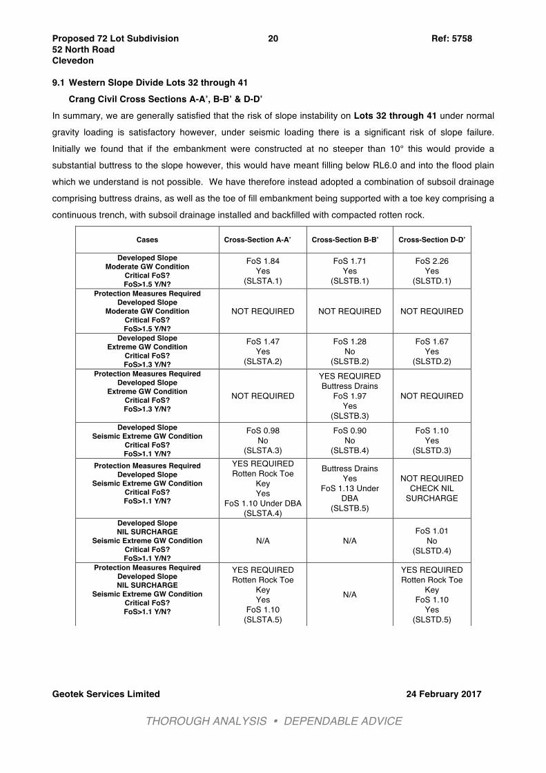
9.1 Western Slope Divide Lots 32 through 41 Crang Civil Cross Sections A-A’, B-B’ & D-D’
In summary, we are generally satisfied that the risk of slope instability on Lots 32 through 41 under normal gravity loading is satisfactory however, under seismic loading there is a significant risk of slope failure. Initially we found that if the embankment were constructed at no steeper than 10° this would provide a substantial buttress to the slope however, this would have meant filling below RL6.0 and into the flood plain which we understand is not possible. We have therefore instead adopted a combination of subsoil drainage comprising buttress drains, as well as the toe of fill embankment being supported with a toe key comprising a continuous trench, with subsoil drainage installed and backfilled with compacted rotten rock.
Cases Cross-Section A-A’ Cross-Section B-B’
Cross-Section D-D’
Developed Slope Moderate GW Condition
Critical FoS? FoS>1.5 Y/N?
FoS 1.84 Yes
(SLSTA.1)
FoS 1.71 Yes
(SLSTB.1)
FoS 2.26 Yes
(SLSTD.1) Protection Measures Required
Developed Slope Moderate GW Condition
Critical FoS? FoS>1.5 Y/N?
NOT REQUIRED NOT REQUIRED NOT REQUIRED
Developed Slope Extreme GW Condition
Critical FoS? FoS>1.3 Y/N?
FoS 1.47 Yes
(SLSTA.2)
FoS 1.28 No
(SLSTB.2)
FoS 1.67 Yes
(SLSTD.2) Protection Measures Required
Developed Slope Extreme GW Condition
Critical FoS? FoS>1.3 Y/N?
NOT REQUIRED
YES REQUIRED Buttress Drains
FoS 1.97 Yes
(SLSTB.3)
NOT REQUIRED
Developed Slope Seismic Extreme GW Condition
Critical FoS? FoS>1.1 Y/N?
FoS 0.98 No
(SLSTA.3)
FoS 0.90 No
(SLSTB.4)
FoS 1.10 Yes
(SLSTD.3) Protection Measures Required
Developed Slope Seismic Extreme GW Condition
Critical FoS? FoS>1.1 Y/N?
YES REQUIRED Rotten Rock Toe
Key Yes
FoS 1.10 Under DBA (SLSTA.4)
Buttress Drains Yes
FoS 1.13 Under DBA
(SLSTB.5)
NOT REQUIRED CHECK NIL
SURCHARGE
Developed Slope NIL SURCHARGE
Seismic Extreme GW Condition Critical FoS? FoS>1.1 Y/N?
N/A N/A FoS 1.01
No (SLSTD.4)
Protection Measures Required Developed Slope NIL SURCHARGE
Seismic Extreme GW Condition Critical FoS? FoS>1.1 Y/N?
YES REQUIRED Rotten Rock Toe
Key Yes
FoS 1.10 (SLSTA.5)
N/A
YES REQUIRED Rotten Rock Toe
Key FoS 1.10
Yes (SLSTD.5)
Proposed 72 Lot Subdivision Ref: 5758 52 North Road Clevedon
Geotek Services Limited 24 February 2017
THOROUGH ANALYSIS ! DEPENDABLE ADVICE !
21
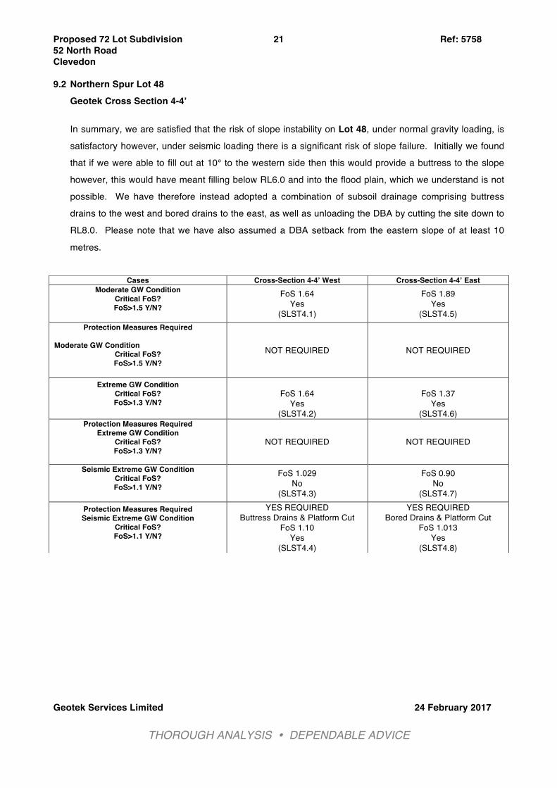
9.2 Northern Spur Lot 48 Geotek Cross Section 4-4’ In summary, we are satisfied that the risk of slope instability on Lot 48, under normal gravity loading, is satisfactory however, under seismic loading there is a significant risk of slope failure. Initially we found that if we were able to fill out at 10° to the western side then this would provide a buttress to the slope however, this would have meant filling below RL6.0 and into the flood plain, which we understand is not possible. We have therefore instead adopted a combination of subsoil drainage comprising buttress drains to the west and bored drains to the east, as well as unloading the DBA by cutting the site down to RL8.0. Please note that we have also assumed a DBA setback from the eastern slope of at least 10
metres.
Cases Cross-Section 4-4’ West Cross-Section 4-4’ East Moderate GW Condition
Critical FoS? FoS>1.5 Y/N?
FoS 1.64 Yes
(SLST4.1)
FoS 1.89 Yes
(SLST4.5) Protection Measures Required
Moderate GW Condition
Critical FoS? FoS>1.5 Y/N?
NOT REQUIRED NOT REQUIRED
Extreme GW Condition Critical FoS? FoS>1.3 Y/N?
FoS 1.64
Yes (SLST4.2)
FoS 1.37
Yes (SLST4.6)
Protection Measures Required Extreme GW Condition
Critical FoS? FoS>1.3 Y/N?
NOT REQUIRED NOT REQUIRED
Seismic Extreme GW Condition Critical FoS? FoS>1.1 Y/N?
FoS 1.029 No
(SLST4.3)
FoS 0.90 No
(SLST4.7) Protection Measures Required Seismic Extreme GW Condition
Critical FoS? FoS>1.1 Y/N?
YES REQUIRED Buttress Drains & Platform Cut
FoS 1.10 Yes
(SLST4.4)
YES REQUIRED Bored Drains & Platform Cut
FoS 1.013 Yes
(SLST4.8)
Proposed 72 Lot Subdivision Ref: 5758 52 North Road Clevedon
Geotek Services Limited 24 February 2017
THOROUGH ANALYSIS ! DEPENDABLE ADVICE !
22
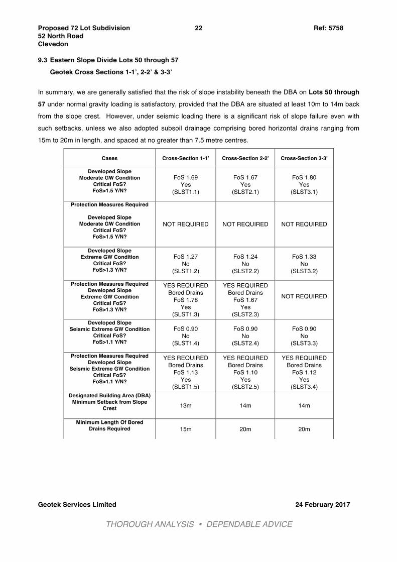
9.3 Eastern Slope Divide Lots 50 through 57 Geotek Cross Sections 1-1’, 2-2’ & 3-3’
In summary, we are generally satisfied that the risk of slope instability beneath the DBA on Lots 50 through 57 under normal gravity loading is satisfactory, provided that the DBA are situated at least 10m to 14m back from the slope crest. However, under seismic loading there is a significant risk of slope failure even with such setbacks, unless we also adopted subsoil drainage comprising bored horizontal drains ranging from 15m to 20m in length, and spaced at no greater than 7.5 metre centres.
Cases Cross-Section 1-1’ Cross-Section 2-2’
Cross-Section 3-3’
Developed Slope Moderate GW Condition
Critical FoS? FoS>1.5 Y/N?
FoS 1.69 Yes
(SLST1.1)
FoS 1.67 Yes
(SLST2.1)
FoS 1.80 Yes
(SLST3.1)
Protection Measures Required
Developed Slope Moderate GW Condition
Critical FoS? FoS>1.5 Y/N?
NOT REQUIRED NOT REQUIRED NOT REQUIRED
Developed Slope Extreme GW Condition
Critical FoS? FoS>1.3 Y/N?
FoS 1.27 No
(SLST1.2)
FoS 1.24 No
(SLST2.2)
FoS 1.33 No
(SLST3.2)
Protection Measures Required Developed Slope
Extreme GW Condition Critical FoS? FoS>1.3 Y/N?
YES REQUIRED Bored Drains
FoS 1.78 Yes
(SLST1.3)
YES REQUIRED Bored Drains
FoS 1.67 Yes
(SLST2.3)
NOT REQUIRED
Developed Slope Seismic Extreme GW Condition
Critical FoS? FoS>1.1 Y/N?
FoS 0.90 No
(SLST1.4)
FoS 0.90 No
(SLST2.4)
FoS 0.90 No
(SLST3.3)
Protection Measures Required Developed Slope
Seismic Extreme GW Condition Critical FoS? FoS>1.1 Y/N?
YES REQUIRED Bored Drains
FoS 1.13 Yes
(SLST1.5)
YES REQUIRED Bored Drains
FoS 1.10 Yes
(SLST2.5)
YES REQUIRED Bored Drains
FoS 1.12 Yes
(SLST3.4) Designated Building Area (DBA)
Minimum Setback from Slope Crest
13m 14m 14m
Minimum Length Of Bored Drains Required
15m 20m 20m

Proposed 72 Lot Subdivision Ref: 5758 52 North Road Clevedon
Geotek Services Limited 24 February 2017
THOROUGH ANALYSIS ! DEPENDABLE ADVICE !
23
9.4 Proposed Accessway 5 Geotek Cross Section 5-5’
The initial development proposal was to utilise a conventional cantilever timber pole retaining wall to support up to 3.2 metres of filled ground however, our investigation revealed the underlying ground conditions comprise significantly weak and sometimes organic soils to at least 5 metres depth, and we therefore considered alternative design options. The option we consider to be most appropriate, is a combination of subgrade ground improvement using geogrid reinforced hardfill, in turn supporting a hardfill embankment.
Cases Cross-Section 5-5’ Cantilever Retaining Wall Moderate GW Condition
Critical FoS? FoS>1.5 Y/N?
FoS 1.20 No
(SLST5.1)
Geogrid Reinforced Hardfill Bank Moderate GW Condition
Critical FoS? FoS>1.5 Y/N?
FoS 2.5 Yes
(SLST5.2)
Cantilever Retaining Wall Extreme GW Condition
Critical FoS? FoS>1.3 Y/N?
FoS 0.97 Yes
(SLST5.3)
Geogrid Reinforced Hardfill Bank Extreme GW Condition
Critical FoS? FoS>1.3 Y/N?
FoS 2.05 Yes
(SLST5.4)
Cantilever Retaining Wall Seismic Extreme GW Condition
Critical FoS? FoS>1.1 Y/N?
FoS 0.76 No
(SLST5.5)
Geogrid Reinforced Hardfill Bank Seismic Extreme GW Condition
Critical FoS? FoS>1.1 Y/N?
FoS 1.16 Yes
(SLST5.6)
Proposed 72 Lot Subdivision Ref: 5758 52 North Road Clevedon
Geotek Services Limited 24 February 2017
THOROUGH ANALYSIS ! DEPENDABLE ADVICE !
24
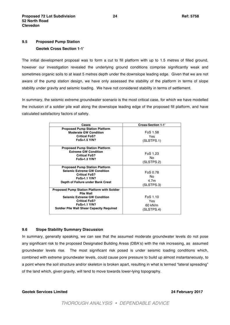
9.5 Proposed Pump Station
Geotek Cross Section 1-1’ The initial development proposal was to form a cut to fill platform with up to 1.5 metres of filled ground, however our investigation revealed the underlying ground conditions comprise significantly weak and sometimes organic soils to at least 5 metres depth under the downslope leading edge. Given that we are not aware of the pump station design, we have only assessed the stability of the platform in terms of slope stability under gravity and seismic loading. We have not considered stability in terms of settlement. In summary, the seismic extreme groundwater scenario is the most critical case, for which we have modelled the inclusion of a soldier pile wall along the downslope leading edge of the proposed fill platform, and have calculated satisfactory factors of safety. 9.6 Slope Stability Summary Discussion In summary, generally speaking, we can see that the assumed moderate groundwater levels do not pose any significant risk to the proposed Designated Building Areas (DBA’s) with the risk increasing, as assumed groundwater levels rise. The most significant risk posed is under seismic loading conditions which, combined with extreme groundwater levels, could cause pore pressure to build up almost instantaneously, to
a point where the soil structure and/or skeleton is broken apart, resulting in what is termed “lateral spreading” of the land which, given gravity, will tend to move towards lower-lying topography.
Cases Cross-Section 1-1’ Proposed Pump Station Platform
Moderate GW Condition Critical FoS? FoS>1.5 Y/N?
FoS 1.58 Yes
(SLSTPS.1)
Proposed Pump Station Platform Extreme GW Condition
Critical FoS? FoS>1.3 Y/N?
FoS 1.23
No (SLSTPS.2)
Proposed Pump Station Platform Seismic Extreme GW Condition
Critical FoS? FoS>1.1 Y/N?
Depth of Failure under Bank Crest
FoS 0.78
No 4.7m
(SLSTPS.3) Proposed Pump Station Platform with Soldier
Pile Wall Seismic Extreme GW Condition
Critical FoS? FoS>1.1 Y/N?
Soldier Pile Wall Shear Capacity Required
FoS 1.10
Yes 60 kN/m
(SLSTPS.4)
Proposed 72 Lot Subdivision Ref: 5758 52 North Road Clevedon
Geotek Services Limited 24 February 2017
THOROUGH ANALYSIS ! DEPENDABLE ADVICE !
25
We have however been able to reduce this risk to a more acceptable level by modelling lowered groundwater levels by incorporating subsoil drainage controls, which will either maintain depressed groundwater levels or allow for more rapid pore pressure dissipation (or path of least resistance), for pore pressure during a moderate seismic event. In some cases subsoil drainage alone is not sufficient to reduce the risk to an acceptable level, and we have chosen to incorporate engineered fill toe keys with additional subsoil drainage along the “at-risk” western slopes, whilst along the steep eastern bank we have increased the set back from such steep slopes. Generally speaking, we have determined that, slopes steeper than 10° are “at-risk” from soil creep under
moderate seismic loading and we therefore anticipate recommending that any future house foundations founded on slopes steeper than 10°, in particular natural soil slopes, will require piled foundations, at least along the downslope leading edge, designed to resist loss of lateral soil support to a depth of 1m.
10. Conclusions & Recommendations On the basis of our site walkovers, aerial photograph review, site observations, record research, intrusive ground investigation comprising hand augers as well as insitu testing and quantitative slope stability assessments as described herein, we are of the opinion that the Designated Building Areas (DBA) as indicated on the appended plan entitled “Designated Building Areas Plan” are generally suitable in terms of section 2 “Earthworks & Geotechnical Requirements” of NZS4404:2010 “Land Development and Subdivision Infrastructure” and section 2.B.2 of the Auckland Council Code of Practice for Land Development & Subdivision, for the support of future dwellings constructed in accordance with NZS3604:2011, subject to satisfactory land development as generally discussed below, and also, specific lot, and/or overall general recommendations to be presented in a Geotechnical Completion Report (GCR), once the earthworks have been completed. 10.1 Slope Stability under Designated Building Areas
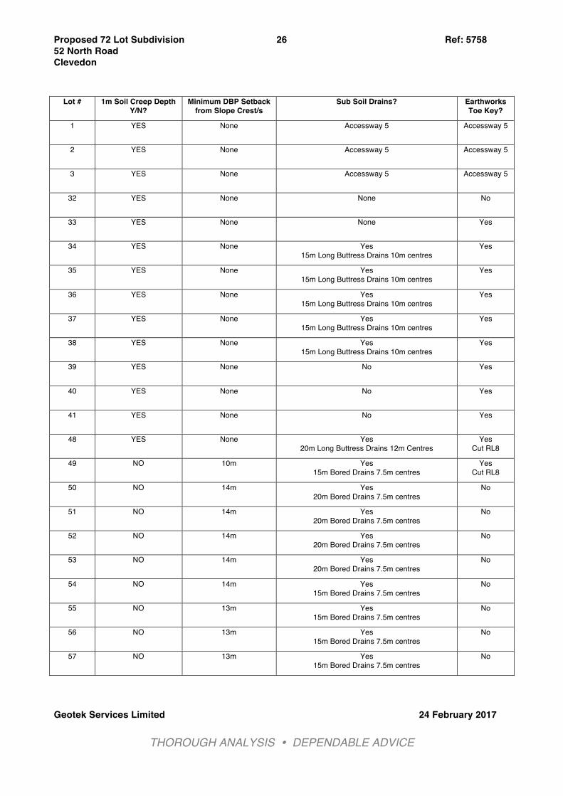
As discussed in the foregoing section, we have undertaken what we consider to be extensive and appropriately conservative quantitative slope stability modeling, for Designated Building Areas “DBA” situated on or within close proximity to slopes steeper than 14°. We consider that, provided the recommended subsoil drains and fill embankment toe keys are constructed at the time of subdivision earthworks and that the recommended set backs from slopes are respected, future buildings constructed within the DBA’s which are designed and constructed in accordance with the limitations
stated in this report, should be exposed to an acceptably low risk of slope stability, with the exception of shallow soil creep. Given that the primary aim of this report was to establish safe and stable DBA’s, the following table is a summary of the recommended mitigation measures required to achieve this on specific “at-risk” lots:
Proposed 72 Lot Subdivision Ref: 5758 52 North Road Clevedon
Geotek Services Limited 24 February 2017
THOROUGH ANALYSIS ! DEPENDABLE ADVICE !
26
Lot # 1m Soil Creep Depth Y/N?
Minimum DBP Setback from Slope Crest/s
Sub Soil Drains? Earthworks Toe Key?
1 YES
None Accessway 5 Accessway 5
2 YES
None Accessway 5 Accessway 5
3 YES
None Accessway 5 Accessway 5
32 YES
None None No
33 YES
None None
Yes
34 YES
None Yes 15m Long Buttress Drains 10m centres
Yes
35 YES
None Yes 15m Long Buttress Drains 10m centres
Yes
36 YES
None Yes 15m Long Buttress Drains 10m centres
Yes
37 YES
None Yes 15m Long Buttress Drains 10m centres
Yes
38 YES
None Yes 15m Long Buttress Drains 10m centres
Yes
39 YES
None No Yes
40 YES
None No Yes
41 YES
None No Yes
48 YES
None Yes 20m Long Buttress Drains 12m Centres
Yes Cut RL8
49 NO 10m Yes 15m Bored Drains 7.5m centres
Yes Cut RL8
50 NO 14m Yes 20m Bored Drains 7.5m centres
No
51 NO 14m Yes 20m Bored Drains 7.5m centres
No
52 NO 14m Yes 20m Bored Drains 7.5m centres
No
53 NO 14m Yes 20m Bored Drains 7.5m centres
No
54 NO 14m Yes 15m Bored Drains 7.5m centres
No
55 NO 13m Yes 15m Bored Drains 7.5m centres
No
56 NO 13m Yes 15m Bored Drains 7.5m centres
No
57 NO 13m Yes 15m Bored Drains 7.5m centres
No
Proposed 72 Lot Subdivision Ref: 5758 52 North Road Clevedon
Geotek Services Limited 24 February 2017
THOROUGH ANALYSIS ! DEPENDABLE ADVICE !
27
Please refer to the preceding section on slope stability as well as the appended site plans and cross sections for the specific drainage measures recommended, as well as the lot specific earthworks.
10.1.1 Engineered Fill Toe Keys to comprise the following:
This key should be 3 metres wide and centred beneath the toe of the proposed engineered filled embankment. The depth of the key will likely vary between 2m to 3m depth. The keys must be dug under the supervision of a Geo-Professional who is familiar with the contents of this report. A 160mm diameter perforated novacoil wrapped in a filter sock should be laid along the invert, before being backfilled with “blue rock” GAP65 to at least 0.5m thickness before placing and compacting “rotten rock”.
Where there are buttress drains underlying the key, the subsoil drains in the key can be connected to these. Where there aren’t any buttress drains, then outlets should be constructed in positions confirmed by a Geo-Professional at the time. These should be filled with at least 1m of “blue rock” GAP65 and then capped with clay and topsoil. The drain outlets should be formalised with rip-rap rock surround, and discharge to the stream. The requirement of a GAP65 (washed, well-graded, blue chip material) is to provide a sufficient filtration medium, so that silt and clay infiltration is reduced, with the filtersock around the novacoil an additional filter. The inspection of the toe key is an important aspect for confirmation of the geological model and they should be considered as trial pit excavations. These will therefore need to be logged by a Geo-Professional and if considered necessary, the assumptions made in our stability models re-assessed, to ensure appropriate soil conditions and parameters have been assumed. These findings and any revised stability models will be incorporated into our GCR.
10.1.2 Sub soil drains to comprise the following:
(i) Trench/Underfill Drain Drains should be dug using a 300 to 500mm wide bucket to depths of up to 4 metres, under the supervision of a Geotechnical Professional who is familiar with the contents of this report. A 160mm diameter perforated novacoil wrapped in a filter sock should be laid along the
invert, before being backfilled with “blue rock” GAP65 to within 0.5 metres of the ground surface, then capped with clay and topsoil. The drain outlets should be formalised with rip-
Proposed 72 Lot Subdivision Ref: 5758 52 North Road Clevedon
Geotek Services Limited 24 February 2017
THOROUGH ANALYSIS ! DEPENDABLE ADVICE !
28
rap rock surround, as well as full face grouting of the trench where it daylights at the stream bank to provide erosion resistance. The requirement of a GAP65 (washed, well-graded, blue chip material) is to provide a sufficient filtration medium, so that silt and clay infiltration is reduced, with the filtersock around the novacoil an additional filter. Inspections of the buttress drains are an important aspect for confirmation of the geological model and they should be considered as trial pit excavations. These will therefore need to be logged by a Geo-Professional and if considered necessary, the assumptions made in our
stability models re-assessed, to ensure appropriate soil conditions and parameters have been assumed. These findings and any revised stability models will be incorporated into our GCR.
(ii) Bored Horizontal Drains Bored horizontal drains should comprise a 65mm diameter slotted PVC pipe wrapped in a filtersock installed into a bored hole of approximately 80mm diameter, with a slight uphill inclination (~2°). Once the bored drains have been installed they must be ‘as-built’ and the outlets surveyed. The drain outlets should be formalised with rip-rap rock surround, but can simply discharge onto the ground.
Only once the Designated Building Areas have been pegged on-site by a Registered Surveyor, can the locations of the drains be confirmed on-site by a Geo-Professional. This must be carried out before construction can commence. On completion the drain outlets will need to be surveyed and staked with steel warratahs so that the locations are not lost in the future. We further recommend that a notification be placed on titles of the lots with these drains, which highlights the necessity for annual inspection of the drain outlets, to ensure they are freely draining and functioning as intended.
Proposed 72 Lot Subdivision Ref: 5758 52 North Road Clevedon
Geotek Services Limited 24 February 2017
THOROUGH ANALYSIS ! DEPENDABLE ADVICE !
29
10.2 Earthworks Operations We stress that the materials we have encountered within the proposed cut areas are largely non-cohesive fine-grained SILTS, with a moisture content that will likely be wet of optimum once below the dessicated crustal zone. Such materials will more than likely prove difficult to work relative to traditional clay soils, and will require careful blending and conditioning before compacting with a sheep’s foot roller. 10.2.1 Preparations For Filling
All debris as well as vegetation, including tree stumps and the root balls themselves, should be removed from site. Any areas comprising pre-existing fill deposits should be cut open by
hydraulic excavator and assessed by ourselves, to determine whether the material is suitable to be used as fill, or otherwise removed. Again, we caution that as the property has been used as a farm in the past, it is possible that buried offal or other rubbish pits may be present, which will need to be removed from the site, and the excavations backfilled to engineered standards.
All topsoil and other unsuitables should be stripped from all cut and fill areas and stockpiled well clear of the works on suitable areas of natural ground. Given the relatively high groundwater conditions encountered beneath the areas, topsoil stripping and site cutting may expose seepages needing tapping drainage, which should comprise perforated underfill drainage wrapped in a filtersock contained within GAP65 metal, and where widespread, drainage blankets, prior to the placing and compaction of filling.
We have identified the presence of pre-existing fill at the head of the eastern gully, which will remove complete excavation and stripping back to competent natural soils. Underfill drainage comprising a 160mm diameter perforated novacoil wrapped in a filter sock should be laid along the invert, before being backfilled with “blue rock” GAP65 to a level at least 0.5 metres ABOVE the drain outlet level.
10.2.2 Fill Compaction & Control
We caution that beneath the generally cohesive soil crust which comprises clays and silts, the materials become less cohesive and much more sensitive to disturbance at depth, making reconstitution of the material difficult, in our experience. For this reason, we recommend that blending the cohesive soils with the deeper non-cohesive silts be
undertaken. If significant volumes of wet and sensitive silts and soils are excavated, it may become necessary to lime and/or cement stabilise the materials to achieve the required undrained shear strength.

Proposed 72 Lot Subdivision Ref: 5758 52 North Road Clevedon
Geotek Services Limited 24 February 2017
THOROUGH ANALYSIS ! DEPENDABLE ADVICE !
30
As a general guide, we recommend placing the soil in loose lift thicknesses of around 200 to 300mm, and compacting using a suitably sized sheep’s foot roller. It is important that the moisture content of the material is at close to an optimum level, in order to achieve successful compaction. On the basis of our experience on surrounding sites with similar materials, we anticipate the optimum moisture content for effective compaction to be around 40%. Although materials can still be compacted if wet or dry of this value, the results may not be acceptable and could require conditioning by drying or wetting as appropriate.
We strongly recommend we select representative samples of the fill so that compaction curve testing can be undertaken by an approved laboratory, prior to commencement of bulk filling operations. In order to provide the most flexibility for likely variations in soil types, it is recommended that earthworks compaction control use the maximum allowable air voids/ minimum allowable shear strength criteria, as follows:-
Air Voids and Shear Vane (for cohesive soils only)
Air Voids Percentage (as defined in NZS 4402:1986)
Undrained Shear Strength (Measured insitu by IANZ calibrated vane)
Maximum Average Value
%
Maximum Single Value
%
Minimum Average Value
kPa
Minimum Single Value
kPa
General Fill 10 12 140 110
Road Fill (top 0.5m) 8 10 150 120
Note: The average value shall be determined over any ten consecutive tests
Proposed 72 Lot Subdivision Ref: 5758 52 North Road Clevedon
Geotek Services Limited 24 February 2017
THOROUGH ANALYSIS ! DEPENDABLE ADVICE !
31
However, the need could arise to cross check results in terms of 95% of the maximum dry density, within the appropriate water content range, as follows:-
Percentage of Dry Density by N.Z. Standard Compaction Test
NZ 4402:1986, test 4.1.1 or equivalent
Allowable Variations From Optimum Water
Content
General fill Within 500mm of
carriageway subgrade
All classes of fill
All classes of fill
Cohesive soil 95% 100% -2% 4%
Highly plastic cohesive soil 92% 97% -2% 5%
Non-cohesive soil 100% 102% -2% 2%
In all cases, the specification gives the minimum average result of any ten consecutive test sites, while that at any single test site should not be more than 5% below the minimum.
Relaxation of the upper limits of the variations from optimum water content may be made by the Certifying Engineer to restrict post-construction swelling of the fill, especially if the natural water contents of cohesive soils are well in excess of their optimum values.
10.2.3 Imported Filling
If imported filling is to be used in conjunction with the insitu materials, it is essential that we are given the opportunity of examining its source or sources, and determining its suitability for inclusion in the earthworks on the basis of observation, investigation and testing as considered necessary.
It will also be necessary for us to inspect all truck loads of imported material for contaminants prior to dumping, if we are going to be in a position to certify the completed works in terms of NZS 4431 and NZS 3604. From a practical standpoint, this may entail stockpiling a day’s deliveries, and then spreading it in the fill area the next day.
10.2.4 Erosion and Sediment Control
All erosion and sediment control should be undertaken in accordance with ARC Technical Publication No. 90 dated March 1999 and the Auckland Council Sediment Control Plan: dated September 1995. Stormwater runoff must be intercepted from all adjoining upslope areas and from areas of the site not affected by the earthworks, by means of appropriately positioned cutoff drains and bunds. Discharges from these drains and bunds should then be routed to suitable watercourses. Any sediment bunds should not need any further geotechnical engineering
Proposed 72 Lot Subdivision Ref: 5758 52 North Road Clevedon
Geotek Services Limited 24 February 2017
THOROUGH ANALYSIS ! DEPENDABLE ADVICE !
32
input at this stage, but should be inspected during construction to confirm the stability of the batter slopes.
10.2.5 Service Pipes and Trenches
All construction work involving trenches must comply with the Construction Act and Regulations, and the Department of Labour publication “Approved Code of Practice for Safety in Excavation & Shafts for Foundations”. A leaflet and further information are available via http://www.worksafe.govt.nz/worksafe/information-guidance/all-guidance-items/acop-excavation-
and-shafts-for-foundations/excavation-acop.pdf Notwithstanding the minimum requirements set by the Department of Labour, the further need for such measures should be carefully assessed during construction of these services. As far as practicable, reticulation work should be confined to the summer earthworks season. No construction difficulties are anticipated through having to excavate bedrock. As is standard industry practice, backfilling of trenches will unlikely be done under engineering supervision, unless instructed otherwise. Therefore the quality of backfilling will be categorised as non-engineered and will need to be “tagged” as such in the Geotechnical Completion Report, where any future building development within the 45° influence rising from the invert of trenches will require specific investigation and/or design, with the exception of those backfilled with engineered hardfill or clayfill which is monitored, tested and certified as such by the supervising Geo-Professional.
10.2.7 Sewer & Stormwater Reticulation
We have not identified any significant service trench excavations apart from SSMHA/5, which shows an invert of 5.3 metres and will require extremely careful construction, and possibly shielding and/or sheet piling. We further caution that trenches deeper than 2 metres, could require trench shields especially if undertaken during period of wet weather which could result in high groundwater levels, as well as weak ground which could be susceptible to collapse. For these reasons we stress that undertaking trench excavations during periods of fine weather in summer will greatly reduce the risk of collapse. Standard bedding should be suitable however there may be zones of weaker soils that may need increased bedding thickness of say 0.3 metres of GAP65 wrapped in geotextile.

Proposed 72 Lot Subdivision Ref: 5758 52 North Road Clevedon
Geotek Services Limited 24 February 2017
THOROUGH ANALYSIS ! DEPENDABLE ADVICE !
33
We recommend that where pipe bedding is situated below RL5.0, the provision of 110mm Novaflo wrapped in filtersock be included to prevent groundwater buildup. These pipes should either drain into stormwater manholes or be daylighted into the flood plain and/or adjacent stream.
Furthermore, we strongly recommend that trench backfill be compacted using a compaction-wheel or a remote pad-foot compactor especially where these services are situated below RL6 and within the zone which we consider could be at moderate risk of liquefaction under seismic loading.
10.3 Proposed Fill Batters
We generally anticipate that fill batters will be NOT formed steeper than 15° (1V:4H). However where localized batters are formed steeper than 15°, careful assessment will need to be undertaken. Akin to restricted development within proximity to slopes steeper than 10° on account of the risk of soil creep, these batters will also require defined restricted development zones, both above and below such earth batters, and will be considered at the time of preparation of the relevant Geotechnical Completion Report. Once the required batter has been achieved, the exposed subgrade should be dressed with topsoil and seeded as soon as possible.
10.4 Proposed Retaining Walls 1, 3 & 5
For the design of cantilever and/or flexible diaphragm retaining walls that can deform sufficiently to mobilize active pressures we recommend calculating coefficients of active lateral earth pressure (Ka) (i.e. timber pole retaining walls not supporting critical structures and/or long-term traffic loads). However for stiff, inflexible retaining walls which are unable to deflect sufficiently to generate active earth pressures, we recommend calculating of coefficients of at-rest lateral earth pressure (Ko) (i.e. concrete and/or masonry retaining walls supporting building loads and/or driveways/car-parking areas). We recommend assuming the following soils parameters for retaining wall design:
Material Type Angle of Internal Friction ø’
Bulk Density g
Undrained Shear Strength (Cu) for Pole Embedment*
Natural Soils/Engineered Earth Fill 28° 18 kN/m3 50 kPa
*For the calculation of pole embedment depths, the Broms method as specified in B1/VM4 may be used provided that depths are not less than 4 pile diameters, for which the above stated undrained shear strength value may be assumed, provided an appropriate strength reduction factor is applied and is subject to confirmation by Engineering inspection during construction.
Proposed 72 Lot Subdivision Ref: 5758 52 North Road Clevedon
Geotek Services Limited 24 February 2017
THOROUGH ANALYSIS ! DEPENDABLE ADVICE !
34
To the above figures please apply an appropriate strength reduction factor for satisfying Ultimate Limit State conditions. Furthermore, the above figures make no allowances for any surcharges, be they ground slopes and/or applied loads, and hence, all retaining wall designs should also accommodate all anticipated upslope surcharges, as well as reduced toe support by existing or proposed excavations and/or slopes. In accordance with good Engineering design principles, all retaining walls should be constructed with rear base drainage down to underside of footing level and backfilled with lightly tamped, free draining
granular material. Care should be taken to avoid excessive compaction adjacent to retaining walls. 10.5 Proposed Retaining Walls 2 & 6 – Accessway 5
The initial development proposal was to utilise a conventional cantilever timber pole retaining wall to support up to 3.2 metres of filled ground, however our investigation revealed the underlying ground conditions comprised significantly weak and sometimes organic soils to at least 5 metres depth, and we therefore considered alternative design options. The option we consider to be most appropriate is a combination of subgrade ground improvement using geogrid reinforced hardfill, in turn supporting a hardfill embankment. As indicated on Section 5-5’ appended, the entire footprint of accessway 5 plus approximately 10 metres beyond each side, will need to be undercut to a depth 1.5 metres below the existing gully level i.e. ~RL3.5. The excavation should then be lined with non-woven geotextile (Strength Class C as per TNZ F7) before placing a layer of multi-directional geogrid such as Secugrid 30/30 or an approved equivalent, with a minimum long-term strength of 20 kN/m in both directions. GAP40 should then be spread and compacted with a smooth-wheeled roller until a minimum CBR of 7% is achieved (corresponding Clegg Impact Values of no less than 10, and averaging 12).
Once 0.5m of hardfill has been placed then a second layer of geo-grid can be placed comprising Secugrid 20/20 or an approved equivalent with a minimum long-term strength of 10 kN/m in both directions followed by another 0.5m thickness of GAP40, before repeating the geogrid layering until a total of 4 layers has been placed. The GAP40 should continue until ~RL6.0 with the geogrid layers above RL5.0 only being installed in the slope itself, so as to avoid being dug into and destroyed
when digging the services later. Once above RL6.0 the fill can comprise engineered earthfill, with a batter not exceeding 24°.
Proposed 72 Lot Subdivision Ref: 5758 52 North Road Clevedon
Geotek Services Limited 24 February 2017
THOROUGH ANALYSIS ! DEPENDABLE ADVICE !
35
Once the filling has reached design level the entire footprint should be pre-loaded with soil up to 2m thick, as measured from the crest of Accessway 5, battered down to the gully to the west and levelled out to the lots to the east. The pre-load should be monitored with settlement markers for a period of at least 3 months with survey undertaken once every 4 weeks. If settlement recorded over the last 4 weeks does not exceed 5mm at any one location, then the pre-load can be removed. If not, the pre-load should remain until such time that 5mm or less is recorded over 4 weeks.
For this reason we recommend that the Accessway 5 geogrid hardfill embankment is constructed as a priority.
10.6 Proposed Pump Station – Retaining Wall 5
The initial development proposal was to form a cut to fill platform with up to 1.5 metres of filled ground, however our investigation revealed the underlying ground conditions comprised significantly weak and sometimes organic soils to at least 5 metres depth under the downslope leading edge. Given that we are not aware of the pump station design we have only assessed the stability of the platform in terms of slope stability under gravity and seismic loading. We have not considered stability in terms of settlement.
In summary, the seismic extreme groundwater scenario is the most critical case, for which we have modelled the inclusion of a soldier pile wall along the downslope leading edge of the proposed fill platform and have calculated satisfactory factors of safety.
As indicated on Section 1-1’ appended, the downslope edge of the platform requires support using a soldier pile which we consider will require at least 8 metre deep piles, designed to resist an ultimate shear force of 60 kN/m for a theoretical failure of 4.7m below the proposed platform surface. This computes to an ultimate overturning moment of 4.7m/3 x 60 kN/m = 94 kN.m/m. At this stage we consider that 500mm diameter reinforced concrete piles spaced at 1.5 metres centres with a capping beam will be a suitable wall design.
10.7 Future House Development Recommendations
Generally speaking, we consider that the majority of the proposed earthworks area within the DBA’s, comprising areas of both cut and fill, are underlain with competent natural soils suitable to support
Proposed 72 Lot Subdivision Ref: 5758 52 North Road Clevedon
Geotek Services Limited 24 February 2017
THOROUGH ANALYSIS ! DEPENDABLE ADVICE !
36
NZS3604 type residential dwellings under normal gravity and static loading, using conventional shallow foundations, albeit with mitigation of expansive soils. We anticipate that, consolidation effects from fills in excess of 3 metres depth in two locations are to be expected, but should have abated within 3 to 6 months of filling to final levels. Nevertheless, we recommend settlement markers be installed in these deeper fill areas, to ensure consolidation is monitored and confirmed as having sufficiently abated. However, we qualitatively consider that there is risk of lateral spreading occurring under seismic loading where buildings (and infrastructure) are situated in close proximity to slopes steeper than
10°. Furthermore, lots situated on land lower than RL9 are at low to moderate risk of superficial liquefaction, given the presence of firm SILTS as well as elevated groundwater. Along the Western Divide we consider Lots 32 through 44, Lot 47 & Lot 48 are at low to moderate risk of relatively superficial instability, whilst Lots 49 through 57 along the Eastern Divide are situated above the very steep bank, which are likely to be at risk of more moderate to deep-seated instability. The remaining lots within the Western Divide (Lots 20 through 27, Lot 30, Lot 31, Lot 45, Lot 46 & Lots 58 through 69) are not considered to be at any significant risk of slope instability and liquefaction, given the increased depth of the groundwater table encountered as well as the generally stiff SILTS underlying the sites. Furthermore, the remaining Lots within the Eastern Divide (Lots 1 through 18) will, for the most part be buttressed and capped with engineered fill, and are not considered to be at any significant risk of slope instability and liquefaction. Whilst we have sufficient soil data to undertake numerical slope stability modelling under both static and preudo-seismic conditions which is detailed in the following section, we anticipate undertaking additional investigation by way of Cone Penetrometer Testing (CPT) during the earthworks programme, with the main objective being to extend our knowledge of the soil profile at depth so that liquefaction analyses can be undertaken to confirm (or otherwise) our risk assessment of liquefaction. This will also provide us with an opportunity to better record groundwater fluctuations for modelling purposes.
Once the subdivisional works have been completed, we anticipate preparing a Geotechnical Completion Report (GCR) confirming (or otherwise) all the above works have been completed and
Proposed 72 Lot Subdivision Ref: 5758 52 North Road Clevedon
Geotek Services Limited 24 February 2017
THOROUGH ANALYSIS ! DEPENDABLE ADVICE !
37
that the required level of stability within the DBA’s have been achieved. In addition, the GCR will provide broad-brush recommendations for the development of a typical light-weight residential dwelling constructed within the DBA’s and in accordance with the requirements of NZS3604:2011 “Timber Frame Buildings”. Such recommendations will most likely be as follows: 10.7.1 Existing Fill
Although we have not identified any extensive deposits of pre-existing fill, given that the land has been used for farming as well as forestry, we caution that there may be unknown areas of pre-existing fill deposits, as well as areas of disturbed ground from various activities over the years. We therefore stress the importance of inspections prior to foundation
construction. Any existing non-engineered fill on the site should not be relied upon for the direct nor indirect support of foundations or floors, and we recommend that it be removed and, if necessary replaced with engineered fill, where it lies beneath any proposed foundations or building footprints.
10.7.2 Soil Creep
Once the Designated Building Areas have been pegged on-site, we will confirm the specific areas within the DBAs that will require specific design to resist loss of lateral soil support, with specific design recommendations included in our GCR.
To reduce the risk of soil creep affecting future foundations we will be recommending such foundations be designed to resist a loss of support of 1.0 metres depth below currently existing ground levels. We will generally recommend using a row of soldier piles to isolate the loss of support to the underside of any on grade floors, or individual foundations if suspended timber floors or decks are at risk.
The extent and details of such foundations will still need to be addressed for each individual development at Building Consent stage.
10.7.3 Foundations for Residential Buildings Subject to the above recommendations, and provided that the earthworks construction and drainage works are carried out in accordance with NZS4404:2004, “Land Development and Subdivision Engineering”, related documents, and Council’s standard specifications where appropriate, then the completed development should be generally suitable for conventional
light timber framed dwellings constructed in accordance with the requirements of NZS3604:2011 “Timber Frame Buildings”, subject to the usual considerations such as the presence of expansive soils.
Proposed 72 Lot Subdivision Ref: 5758 52 North Road Clevedon
Geotek Services Limited 24 February 2017
THOROUGH ANALYSIS ! DEPENDABLE ADVICE !
38
Much of the clayey silt subsoil encountered during this investigation was slightly to moderately plastic, this being a phenomenon common to residual soils in Auckland. The resulting effects of possible shrinkage and swelling in relation to brittle building construction should be considered at the time of preparation of the relevant Geotechnical Completion Report. As a preliminary guide, we estimate the soil to be Moderately reactive to changes in soil moisture, subject to shrink/swell index testing undertaken once earthworks have been completed, on carefully selected lots.
Usual solutions to this problem include controls on planting of certain tree species close to buildings and deepening and/or piling of strip footings beneath blockwork and brick veneer construction, and/or the use of either specifically designed or proprietary stiffened foundation systems, detailed to address this issue.
10.7.4 Cut/Fill Limitations
Given the sensitivity of our stability analyses to additional load placed on the majority of the slopes, we stress that fills greater than 0.3 metres should not be undertaken on this site without further review by a Geo-Professional who is familiar with the contents of this report and express approval in writing of the Council. For this reason we have included in our stability models the distributed surcharge load of both a 2-storey timber framed building, as well as 0.3 metres of hardfill. Furthermore, we recommend limiting cuts to less than 0.3 metres to reduce the risk of removing the crust of more cohesive soils as well as the possible support to adjacent slopes and/or structures.
10.7.5 Stormwater Disposal
All stormwater runoff from roofs and paved areas, plus any water tank overflows, should be collected in sealed pipes and be disposed of to an approved connection. To the best our knowledge, a stormwater connection will be provided within each lot. Any overland flows should be directed away from the building footprint, and under no
circumstances should concentrated overflows from any source discharge into or onto the ground in an uncontrolled fashion.
Proposed 72 Lot Subdivision Ref: 5758 52 North Road Clevedon
Geotek Services Limited 24 February 2017
THOROUGH ANALYSIS ! DEPENDABLE ADVICE !
40
Appendices: Site Plans
GSL Site Investigation Plan – Existing & Proposed Contour (1 sheet) GSL Site Investigation Plan –Proposed Contour Cut/Fill Isopachs (1 sheet) GSL Designated Building Areas (DBA) (1 sheet) Crang Civil Proposed Earthworks (1 sheet) Crang Civil Proposed Cut Fill Plans (2 sheets)
Stratigraphic Summaries Western Divide (1 sheet) Eastern Divide (1 sheet)
Stratigraphic Cross-Sections Cross-section A-A’ (1 sheet) Cross section B-B’ (1 sheet) Cross-section C-C’ (1 sheet) Cross-section D-D’ (1 sheet) Cross-section 1-1’ (1 sheet)
Cross-section 2-2’ (1 sheet) Cross-section 3-3’ (1 sheet) Cross-section 4-4’ (1 sheet) Cross-section 5-5’ (1 sheet)
Slope Stability Analyses Cross-section A-A’ (5 sheets) Cross section B-B’ (5 sheets) Cross-section D-D’ (5 sheets) Cross-section 1-1’ East (5 sheets)
Cross-section 2-2’ (5 sheets) Cross-section 3-3’ (4 sheets) Cross-section 4-4’ (8 sheets) Cross-section 5-5’ (6 sheets) Cross-section 1-1’ West Pump Station (4 sheets)
Investigation Records Hand Auger Borehole Records (52 sheets)
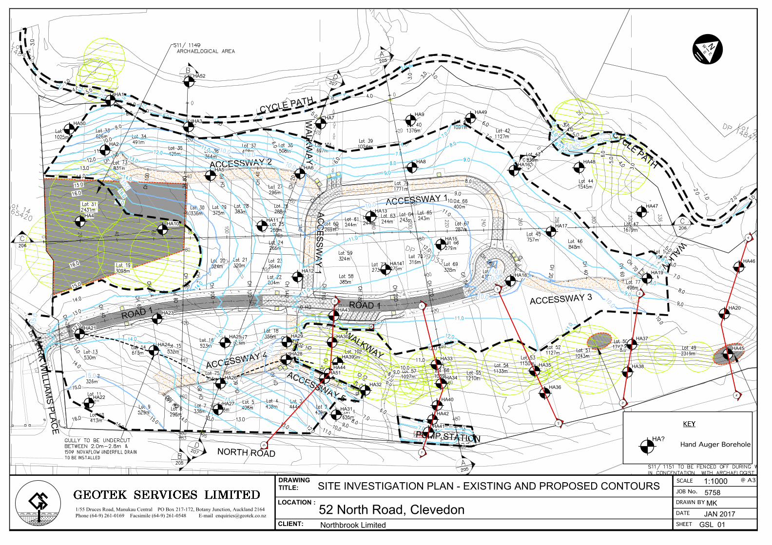
........ of .........DRAWING No REVISION
TITLE
PROJECT
CLIENT
SCALE
1:750
11 A
1:1500
This document and the copyright in this document remain the property of Crang Consulting Ltd. The contents of this documentmay not be reproduced either in whole or in part by any means whatsoever without the prior written consent of Crang Consulting.
COPYRIGHT:
SHEET
A1
A3DESIGNED
DRAWN
DATE
BX
REVISION CHANGES CHECKED DATE
ORIGINAL ISSUE VC 30/11/160
C200
OVERALLEARTHWORKS PLAN
CLEVEDON52 NORTH ROAD
NORTHBROOK
NOV 2016
SHEET 1 SHEET 2
DETAILS ADDED VC 20/01/17A
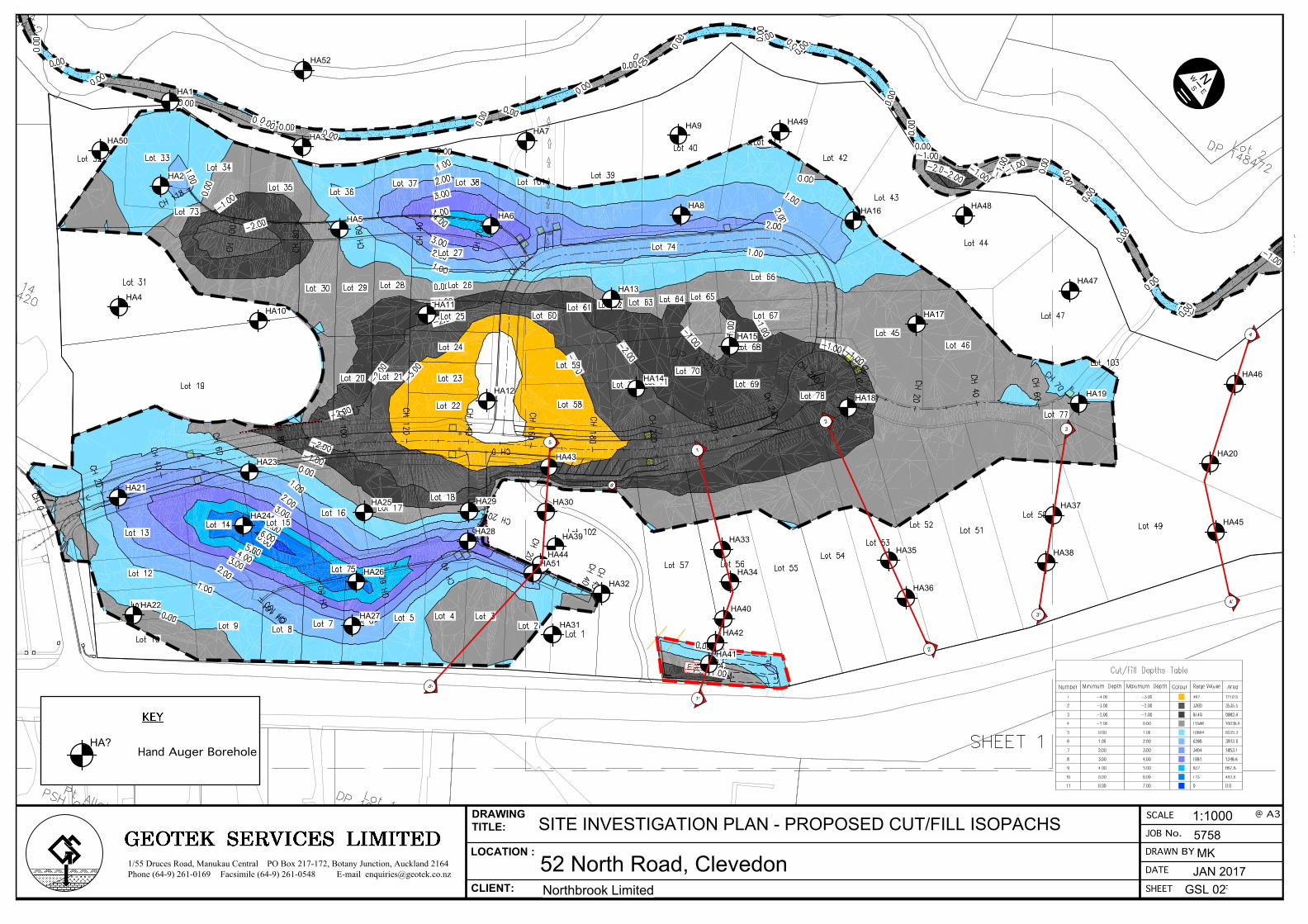
........ of .........DRAWING No REVISION
TITLE
PROJECT
CLIENT
SCALE
1:750
11 A
1:1500
This document and the copyright in this document remain the property of Crang Consulting Ltd. The contents of this documentmay not be reproduced either in whole or in part by any means whatsoever without the prior written consent of Crang Consulting.
COPYRIGHT:
SHEET
A1
A3DESIGNED
DRAWN
DATE
BX
REVISION CHANGES CHECKED DATE
ORIGINAL ISSUE VC 30/11/160
C210
OVERALLCUT-FILL DEPTH PLAN
CLEVEDON52 NORTH ROAD
NORTHBROOK
NOV 2016
DETAIL AMENDED VC 20/01/17A
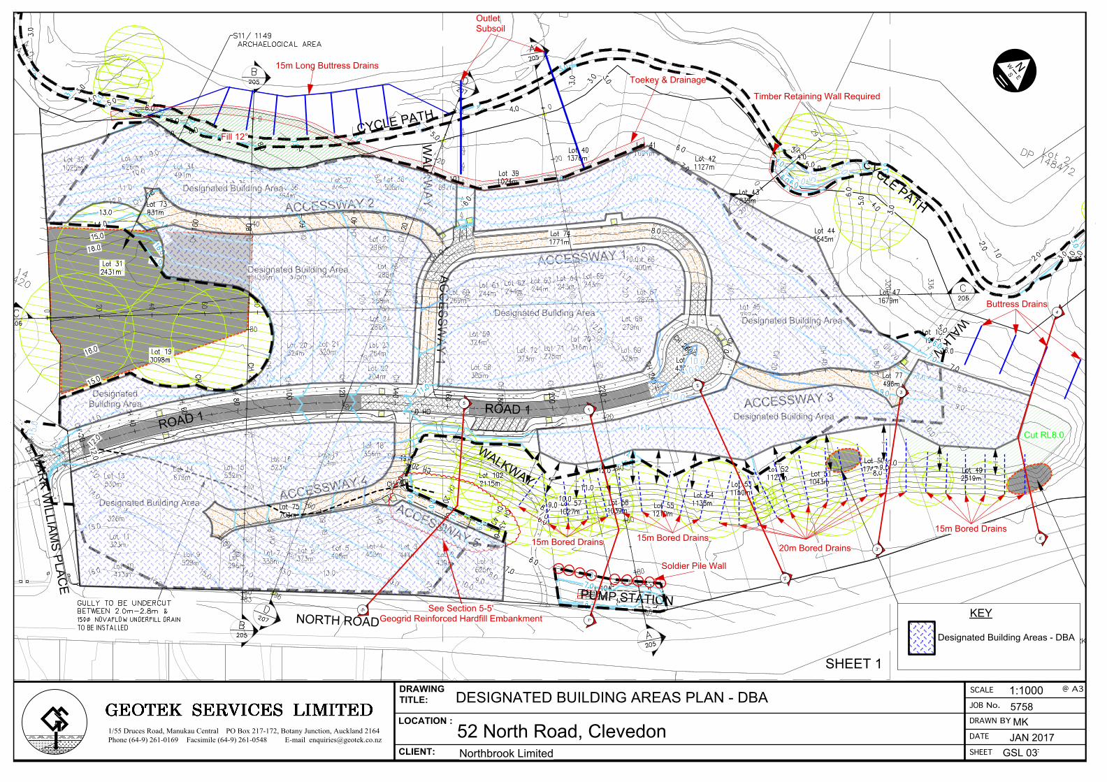
........ of .........DRAWING No REVISION
TITLE
PROJECT
CLIENT
SCALE
1:750
11 A
1:1500
This document and the copyright in this document remain the property of Crang Consulting Ltd. The contents of this documentmay not be reproduced either in whole or in part by any means whatsoever without the prior written consent of Crang Consulting.
COPYRIGHT:
SHEET
A1
A3DESIGNED
DRAWN
DATE
BX
REVISION CHANGES CHECKED DATE
ORIGINAL ISSUE VC 30/11/160
C200
OVERALLEARTHWORKS PLAN
CLEVEDON52 NORTH ROAD
NORTHBROOK
NOV 2016
SHEET 1 SHEET 2
DETAILS ADDED VC 20/01/17A
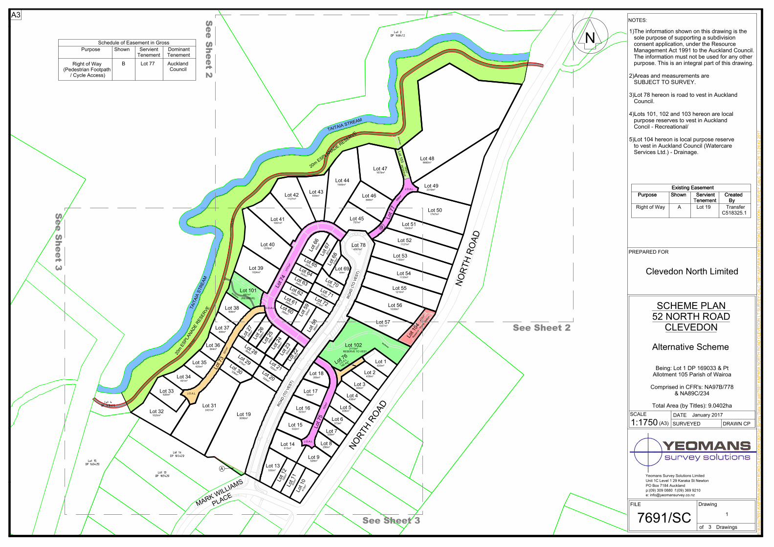
1257+ 52
$'
0$5.
:,//,$
06
3/$&(
20P (63/$1$'( 5(6(59(
20P (6
3/$1$'( 5
(6(59(
7$,7$,$ 675(
$0 1257+
52$'
&\FOH 3DWK
&\FOH
3DWK
:DONZD\
:DONZD\
:DONZD\
288Pð
296Pð
268Pð
266Pð
264Pð
204Pð
320Pð
324Pð
383Pð
375Pð
336Pð
3098Pð
2431Pð
1025Pð
626Pð
491Pð
425Pð
364Pð
408Pð
508Pð
1024Pð
1376Pð
697Pð
1091Pð
1127Pð839Pð
1545Pð
848Pð
757Pð
1043Pð
1127Pð
1747Pð
2319Pð
496Pð
193Pð
6660Pð
1679Pð
1150Pð
1133Pð
1210Pð
1039Pð
1027Pð
5(6(59( 72 9(672115Pð
275Pð
273Pð
316Pð
287P
ð400P
ð
279P
ð
328Pð
243Pð
243Pð
324P
ð
385P
ð
269Pð
244Pð
244Pð
831P
ð
523Pð
532Pð
504Pð
356Pð
613Pð
529Pð
625Pð
439Pð
444Pð
438Pð
408Pð
296Pð
413P
ð323P
ð326P
ð
530Pð
4361Pð
1771Pð
5(6(5
9(
-.2.$./
-.2.$./
-.2.$./
703P
ð
-.2.$./
338Pð
(5(6(59()
/RW 32
/RW 33
/RW 34
/RW 31
/RW 35
/RW 36
/RW 37
/RW 38
/RW 101
/RW 39
/RW 40
/RW 41
/RW 74
/RW 30/RW 73 /RW 29
/RW 28
/RW 26
/RW 27
/RW 25
/RW 24
/RW 23
/RW 22
/RW 21/RW 20
/RW 19
/RW 17
/RW 16
/RW 15
52$'
(72 9(67)
/RW 14
/RW 13
/RW 12
/RW 11
/RW 10
/RW 9
/RW 8
/RW 7
/RW 6
/RW 76
/RW 5
/RW 4
/RW 3
/RW 2
/RW 1
/RW 102
/RW 57
/RW 58
/RW 55
/RW 54
/RW 104
/RW 53
/RW 52
/RW 51
/RW 50
/RW 49
/RW 77
/RW 46
/RW 45
/RW 78
/RW 69
/RW 68/RW 67
/RW 66
/RW 65/RW 64
/RW 63/RW 62
/RW 61/RW 60
/RW 59
/RW 72
/RW 71
52$'
(72 9(6
7)
/RW 47
/RW 44
/RW 43
7$,7$,$ 67
5($0
/RW 42
/RW 103 /RW 48
/RW 70
/RW 56
477Pð
5HVHUYH - 3XPS 6WDWLRQ
244Pð
/RW 75
-.2.$./
192.4P
ð
/RW 18
373Pð
6HH 6KHHW 2
6HH 6KHHW 3
6HH 6
KHHW 2
6HH 6
KHHW 3
%
$
$3
7691/6&3
-DQXDU\ 2017
5:?#-REV?7691-.$,3$5$-1257+
52$'-&/(
9('21?12'
?12G 6XUYH\ 'DWD 6HW MRE?7691 .$,3$5$ 1257+
52$' &/(
9('21 /7 6859(< &$/&
7691 .$,3$5$ 1257+
52$' &/(
9('21 /7 6859(< &$/&
7KX -DQ 26 13:24:42 2017
1
35(3$5(' )25
6&$/( '$7(
6859(<(' '5$:1 &3
),/( 'UDZLQJ
RI 'UDZLQJV
8QLW 1& /HYHO 1 29 .DUDND 6W 1HZWRQ32 %R[ 7184 $XFNODQGS:(09) 309 0880 I:(09) 369 9210H: LQIR#\HRPDQVXUYH\.FR.Q]
<HRPDQV 6XUYH\ 6ROXWLRQV /LPLWHG
127(6:
1)7KH LQIRUPDWLRQ VKRZQ RQ WKLV GUDZLQJ LV WKH VROH SXUSRVH RI VXSSRUWLQJ D VXEGLYLVLRQ FRQVHQW DSSOLFDWLRQ, XQGHU WKH 5HVRXUFH 0DQDJHPHQW $FW 1991 WR WKH $XFNODQG &RXQFLO. 7KH LQIRUPDWLRQ PXVW QRW EH XVHG IRU DQ\ RWKHU SXUSRVH. 7KLV LV DQ LQWHJUDO SDUW RI WKLV GUDZLQJ. 2)$UHDV DQG PHDVXUHPHQWV DUH 68%-(&7 72 6859(<. 3)/RW 78 KHUHRQ LV URDG WR YHVW LQ $XFNODQG &RXQFLO. 4)/RWV 101, 102 DQG 103 KHUHRQ DUH ORFDO SXUSRVH UHVHUYHV WR YHVW LQ $XFNODQG &RQFLO - 5HFUHDWLRQDO/ 5)/RW 104 KHUHRQ LV ORFDO SXUSRVH UHVHUYH WR YHVW LQ $XFNODQG &RXQFLO (:DWHUFDUH 6HUYLFHV /WG.) - 'UDLQDJH.
6&+(0( 3/$152 1257+ 52$'
&/(9('21
1:1750 ($3)
1
%HLQJ: /RW 1 '3 169033 & 3W$OORWPHQW 105 3DULVK RI :DLURD
7RWDO $UHD (E\ 7LWOHV): 9.0402KD
&RPSULVHG LQ &)5'V: 1$97%/778& 1$89&/234
$OWHUQDWLYH 6FKHPH
&OHYHGRQ 1RUWK /LPLWHG
([LVWLQJ (DVHPHQW3XUSRVH 6KRZQ 6HUYLHQW &UHDWHG
7HQHPHQW %\ 5LJKW RI :D\ $ /RW 19 7UDQVIHU
3XUSRVH 6KRZQ 6HUYLHQW &UHDWHG 7HQHPHQW %\
([LVWLQJ (DVHPHQW
&518325.1
&RXQFLO% /RW 77 $XFNODQG
3XUSRVH 6KRZQ 6HUYLHQW 'RPLQDQW 7HQHPHQW 7HQHPHQW
5LJKW RI :D\(3HGHVWULDQ )RRWSDWK / &\FOH $FFHVV)
6FKHGXOH RI (DVHPHQW LQ *URVV