Embed Size (px)
Citation preview
Department of Transport and Main Roads (TMR) Geotechnical Terms and Symbols TMR Form F:GEOT 017/10
TMR Engineering & Technology – Geotechnical Section Form F:GEOT 017/10 – 2019
Geotechnical Terms and Symbols Form
Part 1 – Geotechnical Terms and Tables
Part 2 – Geotechnical Symbols and Abbreviations
Department of Transport and Main Roads (TMR) Geotechnical Terms and Tables
1 TMR Engineering & Technology - Geotechnical Section Form F:GEOT 017/10 – 2019
The terms and tables provided in this form shall be utilised for the geotechnical logging of materials (both naturally occurring and man-made), in conjunction with the Queensland Department of Transport and Main Roads (TMR) Guideline for Geotechnical Logging. The key reference document is Australian Standard AS 1726:2017 Geotechnical site investigations.
Soil Description and Classification
Composition of soils
Particle size definitions (after AS 1726:2017, Table 1)
Fraction Components Subdivision Size1 (mm)
Oversize Boulders (Bo)
> 200
Cobbles (Co) 63 - 200
Coarse grained soils
Gravel (Gr)
Coarse (cGr) 19 - 63
Medium (mGr) 6.7 - 19
Fine (fGr) 2.36 - 6.7
Sand (Sa)
Coarse (cSa) 0.6 - 2.36
Medium (mSa) 0.21 - 0.6
Fine (fSa) 0.075 - 0.21
Fine grained soils Silt (Si)
0.002 - 0.075
Clay (Cly) < 0.002
Note: 1. Corresponding (approximately) to standard sieve sizes
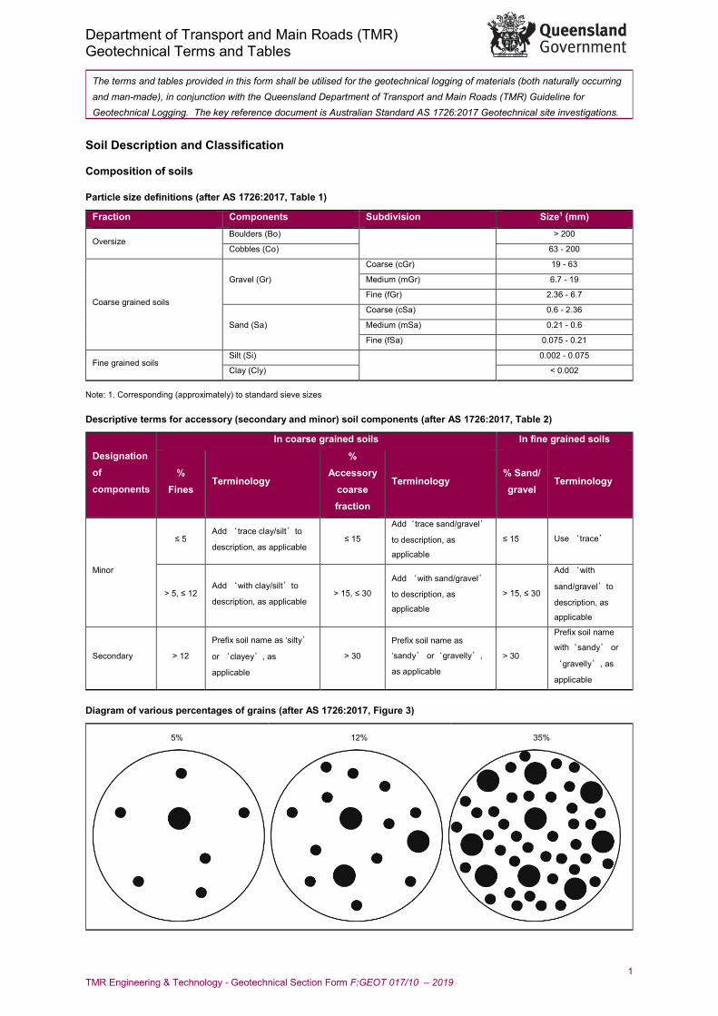
Descriptive terms for accessory (secondary and minor) soil components (after AS 1726:2017, Table 2)
Designation of components
In coarse grained soils In fine grained soils
% Fines
Terminology
% Accessory
coarse fraction
Terminology % Sand/ gravel
Terminology
Minor
≤ 5 Add ‘trace clay/silt’to
description, as applicable ≤ 15
Add‘trace sand/gravel’
to description, as
applicable
≤ 15 Use ‘trace’
> 5, ≤ 12 Add ‘with clay/silt’to
description, as applicable > 15, ≤ 30
Add ‘with sand/gravel’
to description, as
applicable
> 15, ≤ 30
Add ‘with
sand/gravel’to
description, as
applicable
Secondary > 12
Prefix soil name as ‘silty’
or ‘clayey’, as
applicable
> 30
Prefix soil name as
‘sandy’ or‘gravelly’,
as applicable
> 30
Prefix soil name
with‘sandy’ or
‘gravelly’, as
applicable
Diagram of various percentages of grains (after AS 1726:2017, Figure 3)
5% 12% 35%
Department of Transport and Main Roads (TMR) Geotechnical Terms and Tables
2 TMR Engineering & Technology - Geotechnical Section
Identification of organic soils using laboratory tests (after AS 1726:2017, Table 3)
Material Organic content – % of dry mass Inorganic soil < 2
Organic soil 2 to 25
Peat > 25
Descriptive terms for the degree of decomposition of peat (after AS 1726:2017, Table 4)
Term Decomposition Remains Squeeze Fibrous Little or none Clearly recognizable Only water, no solids
Pseudo-fibrous Moderate Mixture of fibres and amorphous paste Turbid water, < 50% solids
Amorphous Full Not recognizable Paste, > 50% solids
Assessment of carbonate content (after AS 1726:2017, Table 5)
Term Reaction to acid Approximate
carbonate content Non-calcareous HCl produces no effervescence Negligible
Calcareous HCl produces weak or sporadic effervescence < 50%
Carbonate HCl produces clear sustained effervescence > 50%
Note: 10% hydrochloric acid is made by taking 10 mL of concentrated HCl acid solution (36% HCl) and making it up to 100 mL. This gives 3.6%
HCl by mass which is about 1.2 molar
Descriptive Terms for Plasticity (after AS 1726:2017, Table 6)
Descriptive term Range of liquid limit for silt Range of liquid limit for clay Non-plastic Not applicable Not applicable
Low plasticity ≤ 50 ≤ 35
Medium plasticity Not applicable > 35 and ≤ 50
High plasticity > 50 > 50
Terms for describing the spread of coarse grained particle sizes (afterAS1726:2017, Claus 6.1.4.11)
Term Description
Well graded Having good representation of all particle sizes from the largest to the smallest (Cu > 4 and 1 < Cc < 3)
Poorly graded With one or more intermediate sizes poorly represented
Gap graded With one or more intermediate sizes absent
Uniformly graded Essentially of one size
Notes: Where D10, D30 and D60 are those grain sizes for which 10%, 30% and 60% of the soil grains are smaller
1. The coefficient of uniformity is given by Cu = (D60 / D10)
2. The coefficient of curvature is given by Cc = (D30)2 / (D10D60)
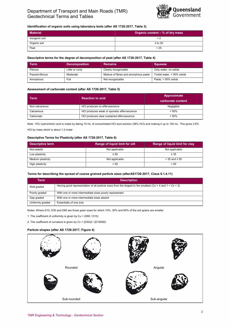
Particle shapes (after AS 1726:2017, Figure 4)
Rounded Angular
Sub-rounded Sub-angular
Department of Transport and Main Roads (TMR) Geotechnical Terms and Tables
3 TMR Engineering & Technology - Geotechnical Section
Note: Essentially two-dimensional particles with the third dimension small by comparison shall by described as ‘flaky’ or ‘platy’
Identification of fine grained soils by visual - tactile methods (after AS 1726:2017, Table 8)
Soil description Identification of inorganic fine-grained soils
Dry strength Dilatancy Toughness and plasticity SILT None to low Slow to rapid Low or thread cannot be formed
Clayey SILT—Clay/silt mixtures of
low plasticity
Low to medium None to slow Low to medium
Silty CLAY—Silt/clay mixtures of
medium plasticity
Medium to high None to slow Medium
High plasticity CLAY High to very high None High
Visual - tactile assessment of fine grained soils (after AS 1726:2017, Table 7)
Dry strength Dilatancy (reaction to shaking) Toughness (consistency near plastic limit)
Mould a pat of soil to the consistency of
putty, adding water if necessary. Allow
the pat to dry completely by oven, sun
or air drying, and then test its strength
by breaking and crumbling between the
fingers. This strength is a measure of
the character and quantity of the
colloidal fraction contained in the soil.
The dry strength increases with
increasing plasticity. High dry strength
is characteristic for clays of the CH
group. A typical inorganic silt
possesses only very low dry strength.
Silty fine sands and silts have about the
same dry strength, but can be
distinguished by feel when powdering
the dried specimen. Fine sand feels
gritty whereas a typical silt has the
smooth feel of flour.
Prepare a pat of moist soil with a volume
of about 10 cm3. Add enough water, if
necessary, to make the soil soft but not
sticky. Shake the pat horizontally in the
palm of the hand, striking vigorously
against the other hand several times. A
positive reaction consists of the
appearance of water on the surface of the
pat which changes to a livery consistency
and becomes glossy. When the sample is
squeezed between the fingers, the water
and gloss disappear from the surface.
The pat stiffens, and finally it cracks or
crumbles. The rapidity of appearance of
water during shaking and its
disappearance during squeezing assist in
identifying the character of the fines in the
soil. Very fine clean sands give the
quickest and most distinct reaction
whereas a plastic clay has no reaction.
Inorganic silt, such as a typical rock flour,
shows a relatively rapid reaction.
Mould a pat of soil to the consistency of putty. If too
dry, add water, and if sticky, the specimen should be
spread out in a thin layer and allowed to lose some
moisture by evaporation. Then, roll a thread of the
soil by hand on a smooth surface or between the
palms until it is about 3 mm in diameter. The thread
is then folded and re-rolled repeatedly. During this
manipulation the moisture content is gradually
reduced, the specimen stiffens, finally loses its
plasticity, and crumbles. When the thread crumbles,
the pieces should be lumped together with a
kneading action. The plastic limit has been reached,
when the soil crumbles at about 3 mm thickness. The
tougher the thread near the plastic limit and the stiffer
the lump when it finally crumbles, the more potent is
the colloidal clay fraction in the soil. Weakness of the
thread at the plastic limit and rapid loss of coherence
of the lump below the plastic limit indicate either
inorganic clay of low plasticity, or materials such as
kaolin-type clays and organic clays which plot below
the A-line. Highly organic clays have a very weak and
spongy feel at the plastic limit.
Criteria for describing dry strength
Criteria for describing dilatancy Criteria for describing toughness
None
The dry specimen crumbles
into powder with mere
pressure of handling.
None No visible change in the
specimen.
Low
Only slight pressure is required
to roll the thread near the plastic
limit. The thread and the lump
are weak and soft. Low
The dry specimen crumbles
into powder with some
finger pressure.
Slow
Water appears slowly on
the surface of the
specimen during shaking
and does not disappear
or disappears slowly upon
squeezing.
Medium
The dry specimen breaks
into pieces or crumbles with
considerable finger
pressure.
Medium
Medium pressure is required to
roll the thread to near the plastic
limit. The thread and the lump
have medium stiffness.
High
The dry specimen cannot
be broken with finger
pressure. Specimen will
break into pieces between
thumb and a hard surface. Rapid
Water appears quickly on
the surface of the
specimen during shaking
and disappears quickly
upon squeezing.
High
Considerable pressure is
required to roll the thread to near
the plastic limit. The thread and
the lump have very high
stiffness. Very
High
The dry specimen cannot
be broken between the
thumb and a hard surface.
Department of Transport and Main Roads (TMR) Geotechnical Terms and Tables
4 TMR Engineering & Technology - Geotechnical Section
Soil classification
Classification of coarse grained soils (after AS 1726:2017, Table 9)
Major divisions Group symbol
Typical names Field classification of sand and gravel Laboratory classification
Coa
rse
grai
ned
soil
(mor
e th
an 6
5% o
f soi
l exc
ludi
ng o
vers
ize
fract
ion
is g
reat
er th
an 0
.075
mm
)
GRAVEL
> 50% of
coarse
fraction is
larger than
2.36mm
GW
Gravel and gravel-
sand mixtures, little
or no fines
Wide range in grain size and substantial
amounts of all intermediate sizes, not enough
fines to bind coarse grains, no dry strength
≤ 5% fines Cu > 4
1 < Cc < 3
GP
Gravel and gravel-
sand mixtures, little
or no fines, uniform
gravels
Predominantly one size or range of sizes with
some intermediate sizes missing, not enough
fines to bind coarse grains, no dry strength
≤ 5% fines
Fails to
comply with
above
GM
Gravel-silt mixtures
and gravel-sand-
silt mixtures
‘Dirty’ materials with excess of non-plastic
fines, zero to medium dry strength
≥ 12% fines,
fines are
silty
Fines
behave as
silt
GC
Gravel-clay
mixtures and
gravel-sand-clay
mixtures
‘Dirty’ materials with excess of plastic fines,
medium to high dry strength
≥ 12% fines,
fines are
clayey
Fines
behave as
clay
SAND
> 50% of
coarse
fraction is
smaller
than
2.36mm
SW
Sand and gravel-
sand mixtures, little
or no fines
Wide range in grain size and substantial
amounts of all intermediate sizes, not enough
fines to bind coarse grains, no dry strength
≤ 5% fines Cu > 6
1 < Cc < 3
SP
Sand and gravel-
sand mixtures, little
or no fines
Predominantly one size or range of sizes with
some intermediate sizes missing, not enough
fines to bind coarse grains, no dry strength
≤ 5% fines
Fails to
comply with
above
SM Sand-silt mixtures ‘Dirty’ materials with excess of non-plastic
fines, zero to medium dry strength
≥ 12% fines,
fines are
silty NA
SC Sand-clay mixtures ‘Dirty’ materials with excess of plastic fines,
medium to high dry strength
≥ 12%, fines
are clayey
Notes:
1. Where the grading is determined from laboratory tests, it is defined by coefficients of curvature Cc and uniformity Cu derived from the particle
size distribution curve, as specified in AS1726:2017, Clause 6.1.4.11
2. For fines contents between 5% and 12%, the soil shall be given a dual classification comprising the two group symbols separated by a dash,
e.g. for a gravel with between 5% and 12% silt fines, the classification is GP-GM
3. Soils that are dominated by boulders, cobbles or peat (Pt) are described separately and are not classified
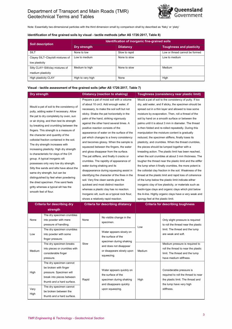
Modified Casagrande chart for classifying silts and clays according to their behaviour (after AS 1726:2017, Figure 5)
Note: The U line is an approximate upper bound for most natural soils. Data which plot above the U line may represent unusual / problem soil
behaviour, or unreliable data and should be considered carefully.
Department of Transport and Main Roads (TMR) Geotechnical Terms and Tables
5 TMR Engineering & Technology - Geotechnical Section
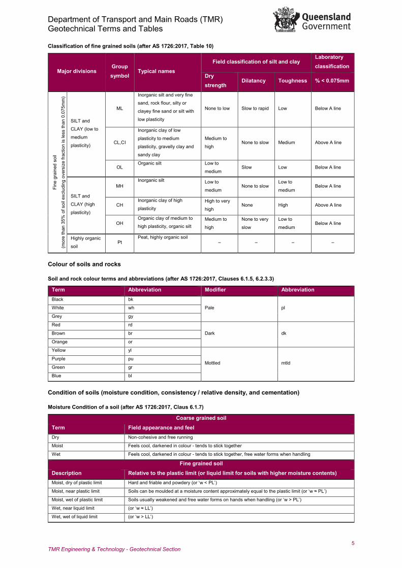
Classification of fine grained soils (after AS 1726:2017, Table 10)
Major divisions Group symbol
Typical names
Field classification of silt and clay Laboratory classification
Dry strength
Dilatancy Toughness % < 0.075mm
Fine
gra
ined
soi
l
(mor
e th
an 3
5% o
f soi
l exc
ludi
ng o
vers
ize
fract
ion
is le
ss th
an 0
.075
mm
)
SILT and
CLAY (low to
medium
plasticity)
ML
Inorganic silt and very fine
sand, rock flour, silty or
clayey fine sand or silt with
low plasticity
None to low Slow to rapid Low Below A line
CL,CI
Inorganic clay of low
plasticity to medium
plasticity, gravelly clay and
sandy clay
Medium to
high None to slow Medium Above A line
OL Organic silt Low to
medium Slow Low Below A line
SILT and
CLAY (high
plasticity)
MH Inorganic silt Low to
medium None to slow
Low to
medium Below A line
CH Inorganic clay of high
plasticity High to very
high None High Above A line
OH Organic clay of medium to
high plasticity, organic silt Medium to
high
None to very
slow
Low to
medium Below A line
Highly organic
soil Pt
Peat, highly organic soil – – – –
Colour of soils and rocks
Soil and rock colour terms and abbreviations (after AS 1726:2017, Clauses 6.1.5, 6.2.3.3)
Term Abbreviation Modifier Abbreviation Black bk
Pale pl White wh
Grey gy
Red rd
Dark dk Brown br
Orange or
Yellow yl
Mottled mtld Purple pu
Green gr
Blue bl
Condition of soils (moisture condition, consistency / relative density, and cementation)
Moisture Condition of a soil (after AS 1726:2017, Claus 6.1.7)
Coarse grained soil
Term Field appearance and feel Dry Non-cohesive and free running
Moist Feels cool, darkened in colour - tends to stick together
Wet Feels cool, darkened in colour - tends to stick together, free water forms when handling
Fine grained soil
Description Relative to the plastic limit (or liquid limit for soils with higher moisture contents) Moist, dry of plastic limit Hard and friable and powdery (or ‘w < PL’)
Moist, near plastic limit Soils can be moulded at a moisture content approximately equal to the plastic limit (or ‘w ≈ PL’)
Moist, wet of plastic limit Soils usually weakened and free water forms on hands when handling (or ‘w > PL’)
Wet, near liquid limit (or ‘w ≈ LL’)
Wet, wet of liquid limit (or ‘w > LL’)
Department of Transport and Main Roads (TMR) Geotechnical Terms and Tables
6 TMR Engineering & Technology - Geotechnical Section
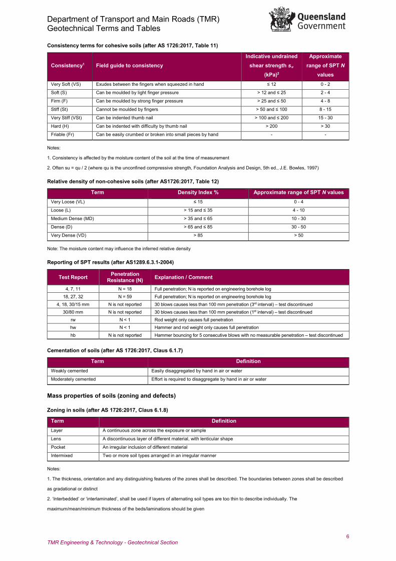
Consistency terms for cohesive soils (after AS 1726:2017, Table 11)
Consistency1 Field guide to consistency Indicative undrained
shear strength su (kPa)2
Approximate range of SPT N
values Very Soft (VS) Exudes between the fingers when squeezed in hand ≤ 12 0 - 2
Soft (S) Can be moulded by light finger pressure > 12 and ≤ 25 2 - 4
Firm (F) Can be moulded by strong finger pressure > 25 and ≤ 50 4 - 8
Stiff (St) Cannot be moulded by fingers > 50 and ≤ 100 8 - 15
Very Stiff (VSt) Can be indented thumb nail > 100 and ≤ 200 15 - 30
Hard (H) Can be indented with difficulty by thumb nail > 200 > 30
Friable (Fr) Can be easily crumbed or broken into small pieces by hand - -
Notes:
1. Consistency is affected by the moisture content of the soil at the time of measurement
2. Often su = qu / 2 (where qu is the unconfined compressive strength, Foundation Analysis and Design, 5th ed., J.E. Bowles, 1997)
Relative density of non-cohesive soils (after AS1726:2017, Table 12)
Term Density Index % Approximate range of SPT N values Very Loose (VL) ≤ 15 0 - 4
Loose (L) > 15 and ≤ 35 4 - 10
Medium Dense (MD) > 35 and ≤ 65 10 - 30
Dense (D) > 65 and ≤ 85 30 - 50
Very Dense (VD) > 85 > 50
Note: The moisture content may influence the inferred relative density
Reporting of SPT results (after AS1289.6.3.1-2004)
Test Report Penetration Resistance (N) Explanation / Comment
4, 7, 11 N = 18 Full penetration; N is reported on engineering borehole log 18, 27, 32 N = 59 Full penetration; N is reported on engineering borehole log
4, 18, 30/15 mm N is not reported 30 blows causes less than 100 mm penetration (3rd interval) – test discontinued 30/80 mm N is not reported 30 blows causes less than 100 mm penetration (1st interval) – test discontinued
rw N < 1 Rod weight only causes full penetration hw N < 1 Hammer and rod weight only causes full penetration
hb N is not reported Hammer bouncing for 5 consecutive blows with no measurable penetration – test discontinued
Cementation of soils (after AS 1726:2017, Claus 6.1.7)
Term Definition Weakly cemented Easily disaggregated by hand in air or water
Moderately cemented Effort is required to disaggregate by hand in air or water
Mass properties of soils (zoning and defects)
Zoning in soils (after AS 1726:2017, Claus 6.1.8)
Term Definition Layer A continuous zone across the exposure or sample
Lens A discontinuous layer of different material, with lenticular shape
Pocket An irregular inclusion of different material
Intermixed Two or more soil types arranged in an irregular manner
Notes:
1. The thickness, orientation and any distinguishing features of the zones shall be described. The boundaries between zones shall be described
as gradational or distinct
2. ‘Interbedded’ or ‘interlaminated’, shall be used if layers of alternating soil types are too thin to describe individually. The
maximum/mean/minimum thickness of the beds/laminations should be given
Department of Transport and Main Roads (TMR) Geotechnical Terms and Tables
7 TMR Engineering & Technology - Geotechnical Section
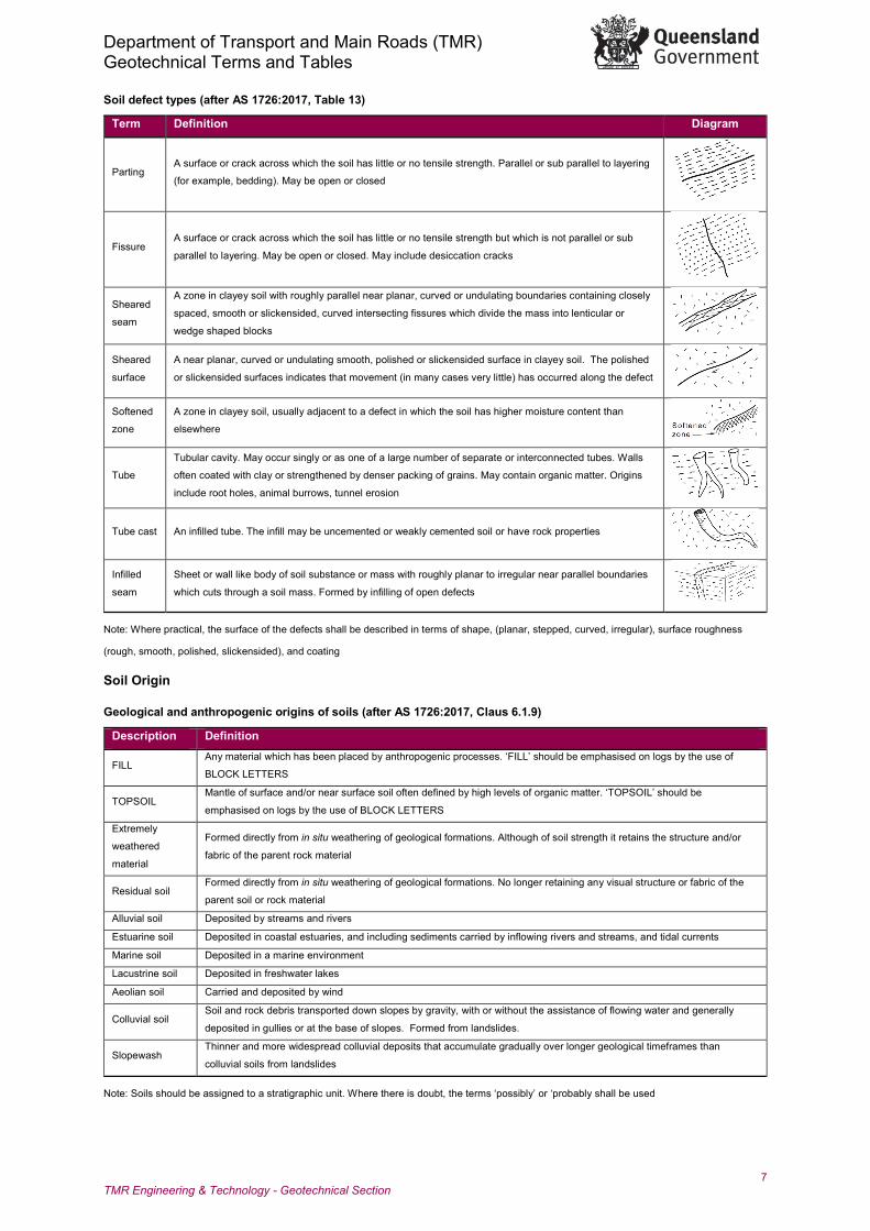
Soil defect types (after AS 1726:2017, Table 13)
Term Definition Diagram
Parting A surface or crack across which the soil has little or no tensile strength. Parallel or sub parallel to layering
(for example, bedding). May be open or closed
Fissure A surface or crack across which the soil has little or no tensile strength but which is not parallel or sub
parallel to layering. May be open or closed. May include desiccation cracks
Sheared
seam
A zone in clayey soil with roughly parallel near planar, curved or undulating boundaries containing closely
spaced, smooth or slickensided, curved intersecting fissures which divide the mass into lenticular or
wedge shaped blocks
Sheared
surface
A near planar, curved or undulating smooth, polished or slickensided surface in clayey soil. The polished
or slickensided surfaces indicates that movement (in many cases very little) has occurred along the defect
Softened
zone
A zone in clayey soil, usually adjacent to a defect in which the soil has higher moisture content than
elsewhere
Tube
Tubular cavity. May occur singly or as one of a large number of separate or interconnected tubes. Walls
often coated with clay or strengthened by denser packing of grains. May contain organic matter. Origins
include root holes, animal burrows, tunnel erosion
Tube cast An infilled tube. The infill may be uncemented or weakly cemented soil or have rock properties
Infilled
seam
Sheet or wall like body of soil substance or mass with roughly planar to irregular near parallel boundaries
which cuts through a soil mass. Formed by infilling of open defects
Note: Where practical, the surface of the defects shall be described in terms of shape, (planar, stepped, curved, irregular), surface roughness
(rough, smooth, polished, slickensided), and coating
Soil Origin
Geological and anthropogenic origins of soils (after AS 1726:2017, Claus 6.1.9)
Description Definition
FILL Any material which has been placed by anthropogenic processes. ‘FILL’ should be emphasised on logs by the use of
BLOCK LETTERS
TOPSOIL Mantle of surface and/or near surface soil often defined by high levels of organic matter. ‘TOPSOIL’ should be
emphasised on logs by the use of BLOCK LETTERS
Extremely
weathered
material
Formed directly from in situ weathering of geological formations. Although of soil strength it retains the structure and/or
fabric of the parent rock material
Residual soil Formed directly from in situ weathering of geological formations. No longer retaining any visual structure or fabric of the
parent soil or rock material
Alluvial soil Deposited by streams and rivers
Estuarine soil Deposited in coastal estuaries, and including sediments carried by inflowing rivers and streams, and tidal currents
Marine soil Deposited in a marine environment
Lacustrine soil Deposited in freshwater lakes
Aeolian soil Carried and deposited by wind
Colluvial soil Soil and rock debris transported down slopes by gravity, with or without the assistance of flowing water and generally
deposited in gullies or at the base of slopes. Formed from landslides.
Slopewash Thinner and more widespread colluvial deposits that accumulate gradually over longer geological timeframes than
colluvial soils from landslides
Note: Soils should be assigned to a stratigraphic unit. Where there is doubt, the terms ‘possibly’ or ‘probably shall be used
Department of Transport and Main Roads (TMR) Geotechnical Terms and Tables
8 TMR Engineering & Technology - Geotechnical Section
Definitions of FILL types (after AS1726:2017, Claus 6.1.11 and Appendix D)
FILL type Definition Controlled Fill placed in accordance with AS 3798 or other controlled method, as demonstrated by construction documentation
Uncontrolled FILL Fill for which no construction documentation is available
Typical characteristics and descriptive terms for FILL materials (after AS 1726:2017, Table 14, and Claus 6.1.11)
Some typical characteristics of FILL
Uncontrolled / non-engineered fill may settle variably, have poor bearing capacity
Very distinct changes in soil profile, unusually variable range of colours
Presence of foreign objects such as glass, plastic, slag
Buried organic matter
‘Cloddiness’ of clay soil indicating previous disturbance by excavation
Generalised terms Typical descriptions
Organic matter
Fibrous peat
Charcoal
Wood fragments
Roots (greater than 2mm diameter)
Root fibres (less than 2mm diameter)
Night soil, putrescible waste
Artificial materials
Oil, bitumen
Masonry, concrete rubble, fibrous plaster, plasterboard, asbestos, fibre cement
Timber pieces, wood shavings, sawdust, leather
Iron filings, drums, steel bars, steel scrap
Slag, chitter, ash, tailings
Rubber tyres, bottles, broken glass
Problematic Soils (after AS 1726:2017, Appendix D)
Type Physical properties Associated risks and engineering problems
Acid
sulfate
soils
(1) Undisturbed - blue-grey, sometimes green-grey, always
wet, generally soft, may contain shells and/or organic matter,
may have associated ‘rotten egg’ H2S gas smell.
(2) Oxidised - brown or mottled yellow and brown, moist to
dry, generally soft to hard.
When the soils are disturbed or exposed to air during
earthworks construction and dewatering, oxidation of
sulphides can occur, thus producing acid and other
environmental contaminants. They pose a risk of causing the
corrosion of buried structures (concrete and steel).
Arid soils High voids ratios, variable mechanical and chemical
weathering, may contain precipitated salts.
May have unusual engineering properties, and can be prone
to accelerated disintegration and lithification.
Tropical
soils
Commonly contain iron and aluminium oxides (sesquioxides),
which may increase soil stiffness and strength, and may limit
soil reactivity.
Fines content of the soils may permanently aggregate under
oven or even air drying, which may result in misleading
laboratory test results.
Collapsible
soils
Possess an open, metastable structure which is developed
via suction or cementation. May collapse under applied load or upon saturation.
Dispersive
soils
Fines include dispersive clays such as montmorillonite (highly
dispersive) and illite (moderately dispersive). Dispersivity is
directly related to clay mineralogy.
Highly erodible when exposed to air and/or water. Risk of
piping when subjected to internal water flow.
Expansive
soils
Fines include expansive clays such as smectite.
Recognisable by development of cracks during dry period
Prone to changes in volume with changes in moisture content
(shrink-swell behaviour) that may be seasonal, or induced by
human activity. Often initiated by altered site drainage
conditions.
Glacial
soils Variably graded, often poorly sorted.
Highly variable nature makes geotechnical characterisation
difficult.
Liquefiable
soils Sands and coarse silts of low relative density.
Loss of shear strength under conditions of high water table,
and usually under cyclic loading.
Sensitive
soils
Clay rich soils with high moisture content, low bulk density
and high porosity, which lose a portion of their strength and
stiffness when remoulded.
Prone to liquefaction. Contribute to instability and progressive
slope failure.
Organic
peat soils Low bulk density and low undrained shear strength. Highly compressible and exhibit creep behaviour.
Department of Transport and Main Roads (TMR) Geotechnical Terms and Tables
9 TMR Engineering & Technology - Geotechnical Section
Rock Description and Classification
Rock name
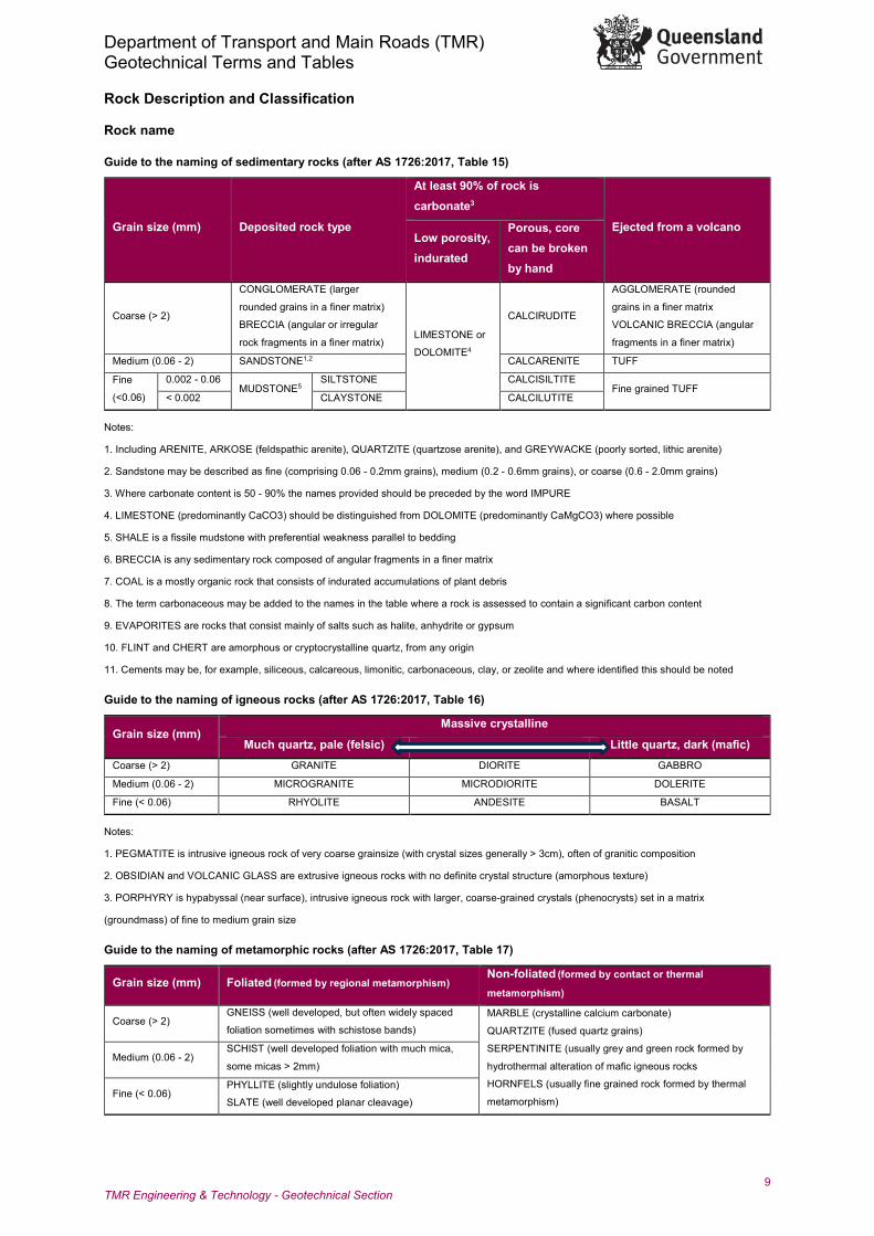
Guide to the naming of sedimentary rocks (after AS 1726:2017, Table 15)
Grain size (mm) Deposited rock type
At least 90% of rock is carbonate3
Ejected from a volcano Low porosity, indurated
Porous, core can be broken by hand
Coarse (> 2)
CONGLOMERATE (larger
rounded grains in a finer matrix)
BRECCIA (angular or irregular
rock fragments in a finer matrix) LIMESTONE or
DOLOMITE4
CALCIRUDITE
AGGLOMERATE (rounded
grains in a finer matrix
VOLCANIC BRECCIA (angular
fragments in a finer matrix)
Medium (0.06 - 2) SANDSTONE1,2 CALCARENITE TUFF
Fine
(<0.06)
0.002 - 0.06 MUDSTONE5
SILTSTONE CALCISILTITE Fine grained TUFF
< 0.002 CLAYSTONE CALCILUTITE
Notes:
1. Including ARENITE, ARKOSE (feldspathic arenite), QUARTZITE (quartzose arenite), and GREYWACKE (poorly sorted, lithic arenite)
2. Sandstone may be described as fine (comprising 0.06 - 0.2mm grains), medium (0.2 - 0.6mm grains), or coarse (0.6 - 2.0mm grains)
3. Where carbonate content is 50 - 90% the names provided should be preceded by the word IMPURE
4. LIMESTONE (predominantly CaCO3) should be distinguished from DOLOMITE (predominantly CaMgCO3) where possible
5. SHALE is a fissile mudstone with preferential weakness parallel to bedding
6. BRECCIA is any sedimentary rock composed of angular fragments in a finer matrix
7. COAL is a mostly organic rock that consists of indurated accumulations of plant debris
8. The term carbonaceous may be added to the names in the table where a rock is assessed to contain a significant carbon content
9. EVAPORITES are rocks that consist mainly of salts such as halite, anhydrite or gypsum
10. FLINT and CHERT are amorphous or cryptocrystalline quartz, from any origin
11. Cements may be, for example, siliceous, calcareous, limonitic, carbonaceous, clay, or zeolite and where identified this should be noted
Guide to the naming of igneous rocks (after AS 1726:2017, Table 16)
Grain size (mm) Massive crystalline
Much quartz, pale (felsic) Little quartz, dark (mafic) Coarse (> 2) GRANITE DIORITE GABBRO
Medium (0.06 - 2) MICROGRANITE MICRODIORITE DOLERITE
Fine (< 0.06) RHYOLITE ANDESITE BASALT
Notes:
1. PEGMATITE is intrusive igneous rock of very coarse grainsize (with crystal sizes generally > 3cm), often of granitic composition
2. OBSIDIAN and VOLCANIC GLASS are extrusive igneous rocks with no definite crystal structure (amorphous texture)
3. PORPHYRY is hypabyssal (near surface), intrusive igneous rock with larger, coarse-grained crystals (phenocrysts) set in a matrix
(groundmass) of fine to medium grain size
Guide to the naming of metamorphic rocks (after AS 1726:2017, Table 17)
Grain size (mm) Foliated (formed by regional metamorphism) Non-foliated (formed by contact or thermal
metamorphism)
Coarse (> 2) GNEISS (well developed, but often widely spaced
foliation sometimes with schistose bands) MARBLE (crystalline calcium carbonate)
QUARTZITE (fused quartz grains)
SERPENTINITE (usually grey and green rock formed by
hydrothermal alteration of mafic igneous rocks
HORNFELS (usually fine grained rock formed by thermal
metamorphism)
Medium (0.06 - 2) SCHIST (well developed foliation with much mica,
some micas > 2mm)
Fine (< 0.06) PHYLLITE (slightly undulose foliation)
SLATE (well developed planar cleavage)
Department of Transport and Main Roads (TMR) Geotechnical Terms and Tables
10 TMR Engineering & Technology - Geotechnical Section
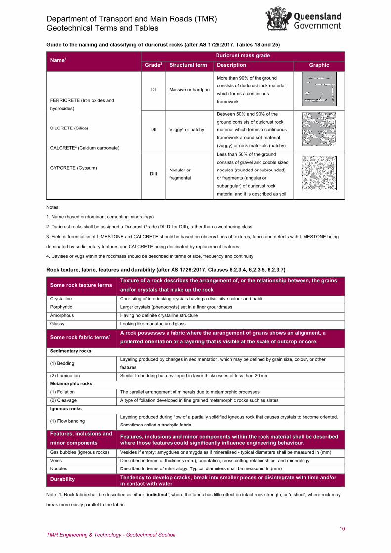
Guide to the naming and classifying of duricrust rocks (after AS 1726:2017, Tables 18 and 25)
Name1 Duricrust mass grade
Grade2 Structural term Description Graphic
FERRICRETE (Iron oxides and
hydroxides)
SILCRETE (Silica)
CALCRETE3 (Calcium carbonate)
GYPCRETE (Gypsum)
DI Massive or hardpan
More than 90% of the ground
consists of duricrust rock material
which forms a continuous
framework
DII Vuggy4 or patchy
Between 50% and 90% of the
ground consists of duricrust rock
material which forms a continuous
framework around soil material
(vuggy) or rock materials (patchy)
DIII Nodular or
fragmental
Less than 50% of the ground
consists of gravel and cobble sized
nodules (rounded or subrounded)
or fragments (angular or
subangular) of duricrust rock
material and it is described as soil
Notes:
1. Name (based on dominant cementing mineralogy)
2. Duricrust rocks shall be assigned a Duricrust Grade (DI, DII or DIII), rather than a weathering class
3. Field differentiation of LIMESTONE and CALCRETE should be based on observations of textures, fabric and defects with LIMESTONE being
dominated by sedimentary features and CALCRETE being dominated by replacement features
4. Cavities or vugs within the rockmass should be described in terms of size, frequency and continuity
Rock texture, fabric, features and durability (after AS 1726:2017, Clauses 6.2.3.4, 6.2.3.5, 6.2.3.7)
Some rock texture terms Texture of a rock describes the arrangement of, or the relationship between, the grains and/or crystals that make up the rock
Crystalline Consisting of interlocking crystals having a distinctive colour and habit
Porphyritic Larger crystals (phenocrysts) set in a finer groundmass
Amorphous Having no definite crystalline structure
Glassy Looking like manufactured glass
Some rock fabric terms1 A rock possesses a fabric where the arrangement of grains shows an alignment, a preferred orientation or a layering that is visible at the scale of outcrop or core.
Sedimentary rocks
(1) Bedding Layering produced by changes in sedimentation, which may be defined by grain size, colour, or other
features
(2) Lamination Similar to bedding but developed in layer thicknesses of less than 20 mm
Metamorphic rocks
(1) Foliation The parallel arrangement of minerals due to metamorphic processes
(2) Cleavage A type of foliation developed in fine grained metamorphic rocks such as slates
Igneous rocks
(1) Flow banding Layering produced during flow of a partially solidified igneous rock that causes crystals to become oriented.
Sometimes called a trachytic fabric
Features, inclusions and minor components
Features, inclusions and minor components within the rock material shall be described where those features could significantly influence engineering behaviour.
Gas bubbles (igneous rocks) Vesicles if empty; amygdules or amygdales if mineralised - typical diameters shall be measured in (mm)
Veins Described in terms of thickness (mm), orientation, cross cutting relationships, and mineralogy
Nodules Described in terms of mineralogy. Typical diameters shall be measured in (mm)
Durability Tendency to develop cracks, break into smaller pieces or disintegrate with time and/or in contact with water
Note: 1. Rock fabric shall be described as either ‘indistinct’, where the fabric has little effect on intact rock strength; or ‘distinct’, where rock may
break more easily parallel to the fabric
Department of Transport and Main Roads (TMR) Geotechnical Terms and Tables
11 TMR Engineering & Technology - Geotechnical Section
Rock classification
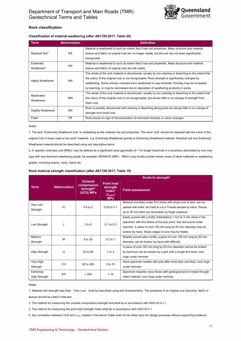
Classification of material weathering (after AS1726:2017, Table 20)
Term Abbreviation Definition
Residual Soil1 RS
Material is weathered to such an extent that it has soil properties. Mass structure and material
texture and fabric of original rock are no longer visible, but the soil has not been significantly
transported.
Extremely
Weathered1 XW
Material is weathered to such an extent that it has soil properties. Mass structure and material
texture and fabric of original rock are still visible.
Highly Weathered HW
The whole of the rock material is discoloured, usually by iron staining or bleaching to the extent that
the colour of the original rock is not recognizable. Rock strength is significantly changed by
weathering. Some primary minerals have weathered to clay minerals. Porosity may be increased
by leaching, or may be decreased due to deposition of weathering products in pores.
Moderately
Weathered MW
The whole of the rock material is discoloured, usually by iron staining or bleaching to the extent that
the colour of the original rock is not recognizable, but shows little or no change of strength from
fresh rock.
Slightly Weathered SW Rock is partially discoloured with staining or bleaching along joints but shows little or no change of
strength from fresh rock.
Fresh FR Rock shows no sign of decomposition of individual minerals or colour changes.
Notes:
1. The term ‘Extremely Weathered rock’ is misleading as the material has soil properties. The word ‘rock’ should be replaced with the name of the
original rock in lower case or the word ‘material’, e.g. Extremely Weathered granite or Extremely Weathered material. Residual soil and Extremely
Weathered material should be described using soil descriptive terms
2. A ‘specific rockmass unit (RMU)’ may be defined as a significant zone (generally of > 1m length downhole in a borehole) dominated by one rock
type with one dominant weathering grade, for example ‘GRANITE (MW)’. RMU’s may locally contain lesser zones of other materials or weathering
grades, including seams, veins, dykes etc.
Rock material strength classification (after AS1726:2017, Table 19)
Term Abbreviation Uniaxial
compressive strength2
(UCS) MPa
Guide to strength1
Point load strength index2 (Is(50)) MPa
Field assessment
Very Low
Strength VL 0.6 to 2 0.03 to 0.1
Material crumbles under firm blows with sharp end of pick; can be
peeled with knife; too hard to cut a Triaxial sample by hand. Pieces
up to 30 mm thick can be broken by finger pressure.
Low Strength L 2 to 6 0.1 to 0.3
Easily scored with a knife; indentations 1 mm to 3 mm show in the
specimen with firm blows of the pick point; has dull sound under
hammer. A piece of core 150 mm long by 50 mm diameter may be
broken by hand. Sharp edges of core may be friable.
Medium
Strength M 6 to 20 0.3 to 1
Readily scored with a knife; a piece of core 150 mm long by 50 mm
diameter can be broken by hand with difficulty
High Strength H 20 to 60 1 to 3
A piece of core 150 mm long by 50 mm diameter cannot be broken
by hand but can be broken by a pick with a single firm blow; rock
rings under hammer.
Very High
Strength VH 60 to 200 3 to 10
Hand specimen breaks with pick after more than one blow; rock rings
under hammer.
Extremely
High Strength EH > 200 > 10
Specimen requires many blows with geological pick to break through
intact material; rock rings under hammer
Notes:
1. Material with strength less than‘Very Low’shall be described using soil characteristics. The presence of an original rock structure, fabric or
texture should be noted if relevant
2. The method for measuring the uniaxial compressive strength and shall be in accordance with AS4133.4.2.1
3. The method for measuring the point load strength index shall be in accordance with AS4133.4.1
4. Any correlation between UCS and Is(50) implied in the above Table shall not be relied upon for design purposes without supporting evidence
Department of Transport and Main Roads (TMR) Geotechnical Terms and Tables
12 TMR Engineering & Technology - Geotechnical Section
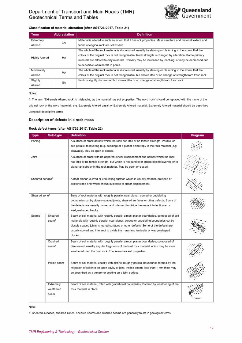
Classification of material alteration (after AS1726:2017, Table 21)
Term Abbreviation Definition Extremely
Altered1 XA
Material is altered to such an extent that it has soil properties. Mass structure and material texture and
fabric of original rock are still visible.
Highly Altered HA
The whole of the rock material is discoloured, usually by staining or bleaching to the extent that the
colour of the original rock is not recognizable. Rock strength is changed by alteration. Some primary
minerals are altered to clay minerals. Porosity may be increased by leaching, or may be decreased due
to deposition of minerals in pores.
Moderately
Altered MA
The whole of the rock material is discoloured, usually by staining or bleaching to the extent that the
colour of the original rock is not recognizable, but shows little or no change of strength from fresh rock.
Slightly
Altered SA
Rock is slightly discoloured but shows little or no change of strength from fresh rock.
Notes:
1. The term ‘Extremely Altered rock’ is misleading as the material has soil properties. The word ‘rock’ should be replaced with the name of the
original rock or the word ‘material’, e.g. Extremely Altered basalt or Extremely Altered material. Extremely Altered material should be described
using soil descriptive terms
Description of defects in a rock mass
Rock defect types (after AS1726:2017, Table 22)
Type Sub-type Definition Diagram Parting A surface or crack across which the rock has little or no tensile strength. Parallel or
sub-parallel to layering (e.g. bedding) or a planar anisotropy in the rock material (e.g.
cleavage). May be open or closed. Joint A surface or crack with no apparent shear displacement and across which the rock
has little or no tensile strength, but which is not parallel or subparallel to layering or to
planar anisotropy in the rock material. May be open or closed.
Sheared surface1 A near planar, curved or undulating surface which is usually smooth, polished or
slickensided and which shows evidence of shear displacement.
Sheared zone1 Zone of rock material with roughly parallel near planar, curved or undulating
boundaries cut by closely spaced joints, sheared surfaces or other defects. Some of
the defects are usually curved and intersect to divide the mass into lenticular or
wedge-shaped blocks. Seams Sheared
seam1
Seam of soil material with roughly parallel almost planar boundaries, composed of soil
materials with roughly parallel near planar, curved or undulating boundaries cut by
closely spaced joints, sheared surfaces or other defects. Some of the defects are
usually curved and intersect to divide the mass into lenticular or wedge-shaped
blocks. Crushed
seam1
Seam of soil material with roughly parallel almost planar boundaries, composed of
disoriented, usually angular fragments of the host rock material which may be more
weathered than the host rock. The seam has soil properties.
Infilled seam Seam of soil material usually with distinct roughly parallel boundaries formed by the
migration of soil into an open cavity or joint, infilled seams less than 1 mm thick may
be described as a veneer or coating on a joint surface.
Extremely
weathered
seam
Seam of soil material, often with gradational boundaries. Formed by weathering of the
rock material in place.
Note:
1. Sheared surfaces, sheared zones, sheared seams and crushed seams are generally faults in geological terms
Department of Transport and Main Roads (TMR) Geotechnical Terms and Tables
13 TMR Engineering & Technology - Geotechnical Section
Rock defect angle of incidence1 (un-orientated drill core)
Angle of incidence (group range)2 Descriptor 0° - 15° sub horizontal
15° - 30° gentle
30° - 45° moderate
45° - 60° steep
60° - 75° very steep
75° - 90° sub vertical
Note:
1. Angle measured between defect and the normal to the core-axis (the horizontal plane for vertical boreholes)
2. For a specific rockmass unit (RMU), defects may be grouped according to the above ranges (or to more narrow ranges where appropriate). The
number of defects within a group range shall be recorded per metre of core. (Note that such groupings are not necessarily defect sets, and a
group frequency is not same as the ‘Fracture Index’, as defined in AS1726:2017, Clause 6.2.9.3
Rock defect surface description (after AS1726:2017, Claus 6.2.5.4)
Surface Roughness
Abbreviation Definition Surface Shape1
Abbreviation Definition
Very rough VRo
Many large surface
irregularities (amplitude
generally more than 1 mm).
Feels like, or coarser than very
coarse sand paper.
Planar Pln The defect does not vary in
orientation
Rough Ro
Many small surface
irregularities (amplitude
generally less than 1 mm).
Feels like fine to coarse sand
paper.
Curved Cvd The defect has a gradual
change in orientation
Smooth Sm Smooth to touch. Few or no
surface irregularities. Undulating Und
The defect has a wavy
surface
Polished Po Shiny smooth surface. Stepped Stp The defect has one or more
well defined steps
Slickensided Sl Grooved or striated surface,
usually polished. Irregular Irr
The defect has many sharp
changes of orientation
Notes:
1. Although the surface roughness of defects can be described at all scales of observation, the overall shape of the defect surface can usually be
observed only at medium and large scale. For example, a defect which appears planar in a 50 mm diameter drill core may be described as curved,
undulating or stepped when observed in outcrop where more of the defect is visible.
2. At the medium scale of observation (100mm to 1m), description of the roughness of the surface shall be enhanced by description of the shape
of the defect surface using the terms in the above Table, and as illustrated in AS1726:2017, Figure 7
3. For medium scale (100mm to 1m) and large scale (1m to 10m) exposures, defect wavelength and amplitude of asperities should be measured
appropriately in (mm) or (m) as per AS1726:2017, Figure 8. Surface roughness may be alternatively characterised by the joint roughness
coefficient (JRC), using the profiles provided in AS1726:2017, Figure 9
4. For large scale exposures, measurements of defect waviness for may be made as per AS1726:2017, Figure 10
Department of Transport and Main Roads (TMR) Geotechnical Terms and Tables
14 TMR Engineering & Technology - Geotechnical Section
Rock defect aperture and infill descriptors (after AS1726:2017 Claus 6.2.5.2 and Claus 6.2.5.5)
Defect Aperture Defect Infill
Term Abbreviation Definition Term Abbreviation Definition
Open1 OP
Defects with visible
aperture, with or without
infill
Clean Cn No visible coating
Filled FL Open defects with infill of
less than 1mm thickness Stained Stn
No visible coating, but
surfaces are discoloured
Tight TI
Defects with no
appreciable aperture or
measurable asperity
Veneer Vr
A visible coating of soil or
mineral, too thin to
measure; may be patchy
Healed2 HD
Tight defects that have
been re-cemented by
minerals such as calcite
and chlorite
Coating3 Ct
A visible, measureable
coating of up to 1mm
thickness
Notes:
1. Aperture of open defects shall be measured in millimetres
2. Healed defects generally possess some tensile strength across the defect surface, but the re-cemented strength is less than that of the
rockmass
3. Where possible the mineralogy of the infill shall be identified. Soil material thicker than 1mm shall be described using defect terms (for example,
infilled seam). Rock material thicker than 1mm shall be described as veins
Detailed rock core logging
Detailed Weathering, Intact Strength and Defect Spacing1
TMR Core Logging Data Input Sheet (Form F:GEOT199) shall be used to collate detailed downhole data for weathering, intact strength and defect
spacing. This data informs the detailed weathering column and the intact strength and defect spacing histograms on the GEOTECHNICAL
BOREHOLE LOG.
Detailed rock defect spacing description (after ISO14689:2017(E) and BS5930:1999
Defect Spacing Descriptors1 Rock Fabric Thickness Descriptors2 (Stratification)
Spacing/Width (mm) Descriptor Symbol Descriptor Spacing/Width (mm)
Thinly Laminated < 6 <20 Extremely Close EC Thickly Laminated 6 – 20
20 – 60 Very Close VC Very Thinly Bedded 20 – 60
60 – 200 Close C Thinly Bedded 60 – 200 200 – 600 Medium M Medium Bedded 200 – 600 600 – 2000 Wide W Thickly Bedded 600 – 2000
2000 – 6000 Very Wide VW Very Thickly Bedded > 2000
Notes:
1. Rock defects are termed as ‘discontinuities’ in ISO14689:2017(E) and BS5930:1999. A distinction is drawn in BS5930:1999 between
‘mechanical discontinuities’, which are already open and present in the rock, and ‘integral discontinuities’, which are built-in potential planes of
weakness. Rock fabrics are essentially integral discontinuities, either distinct or indistinct depending on the extent of their effect on intact rock
strength
2. The terms ‘laminated’ and ‘bedded’ are rock fabric descriptors applicable to sedimentary rock. For igneous and metamorphic rock fabrics, use
the above listed defect spacing descriptors
3. The above listed defect spacing descriptors should be used to define the frequency of defects, i.e. the spacing between successive defects, (or
the mean defect spacing for zones of relatively broken rock); Alternatively, defect frequency should be measured by the ‘Fracture Index’, which is
the number of defects per metre of core (AS1726:2017, Claus 6.2.9.3)
4. Defect set spacing is applicable to defects of similar orientation and nature, and shall be measured perpendicular to the particular defect set,
and recorded as a mean average. Defect sets may be discerned visually in outcrop, orientated core, or by use of borehole imaging techniques
Department of Transport and Main Roads (TMR) Geotechnical Terms and Tables
15 TMR Engineering & Technology - Geotechnical Section
Detailed Defect Description
TMR Detailed Defect Description Log (Form F:GEOT533) shall be used to collate descriptions for individual defects, (when the project requires).
Defect persistence (length) and nature of terminations (after AS1726:2017, Claus 6.2.5.6)
Defect end condition Defect starts and / or ends outside the extent of the exposure
Defect terminates within the rock mass
Defect terminates at an intersecting defect
Note: Rock defect persistence shall be measured in millimetres and metres as appropriate to the project requirements and scale of observation
Parameters related to core drilling (TCR and RQD)
Total core recovery (TCR) % TCR = (Length of core recovered) / (Length of core run) x 100%
Rock quality designation (RQD) % RQD (per RMU) = (Σ Length of intact core pieces > 100 mm in length) / (Length of specific rockmass unit) x100%
RQD (per CR) = (Σ Length of intact core pieces > 100 mm in length) / (Length of core run) x100%
Notes:
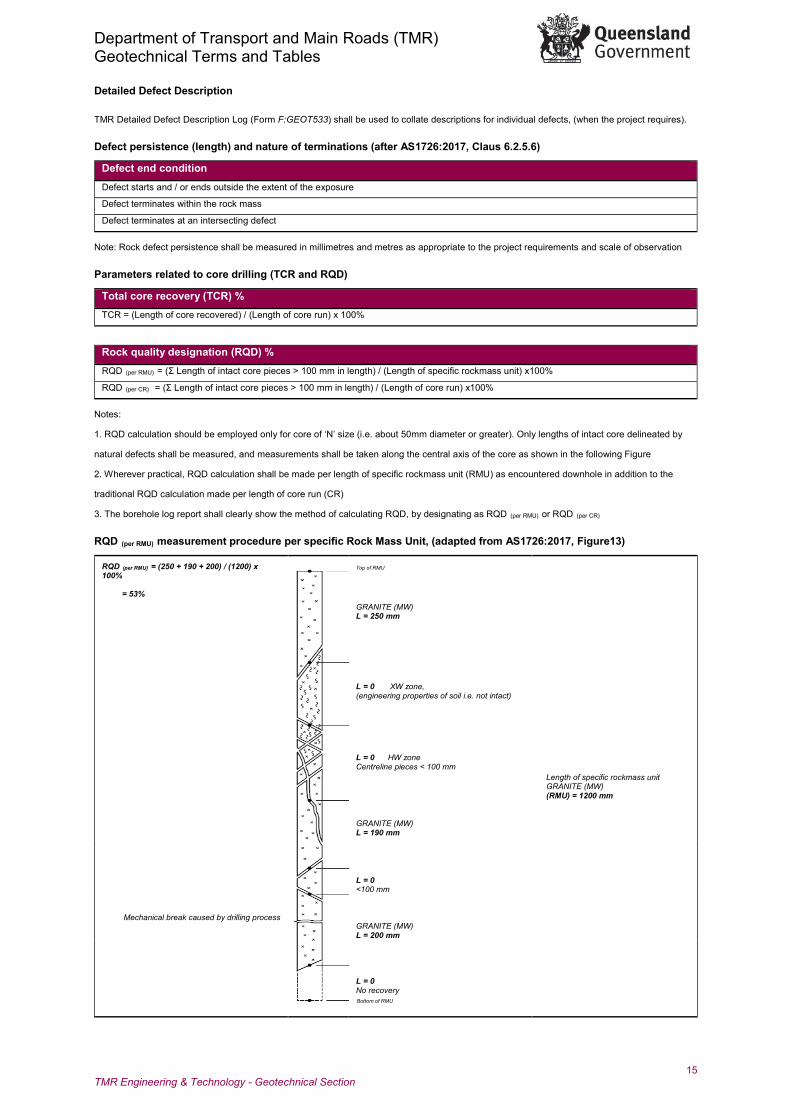
1. RQD calculation should be employed only for core of ‘N’ size (i.e. about 50mm diameter or greater). Only lengths of intact core delineated by
natural defects shall be measured, and measurements shall be taken along the central axis of the core as shown in the following Figure
2. Wherever practical, RQD calculation shall be made per length of specific rockmass unit (RMU) as encountered downhole in addition to the
traditional RQD calculation made per length of core run (CR)
3. The borehole log report shall clearly show the method of calculating RQD, by designating as RQD (per RMU) or RQD (per CR)
RQD (per RMU) measurement procedure per specific Rock Mass Unit, (adapted from AS1726:2017, Figure13)
RQD (per RMU) = (250 + 190 + 200) / (1200) x 100% = 53%
Top of RMU
GRANITE (MW) L = 250 mm
Length of specific rockmass unit GRANITE (MW) (RMU) = 1200 mm
L = 0 XW zone, (engineering properties of soil i.e. not intact)
L = 0 HW zone Centreline pieces < 100 mm
GRANITE (MW) L = 190 mm
L = 0 <100 mm
Mechanical break caused by drilling process
GRANITE (MW) L = 200 mm
L = 0 No recovery Bottom of RMU
Department of Transport and Main Roads (TMR) Geotechnical Terms and Tables
16 TMR Engineering & Technology - Geotechnical Section
Rockmass Characterisation Rockmass weathering grades (after AS1726:2017, Table 24)
Grade Descriptive term IA Fresh; no visible sign of rock material weathering
IB Fresh except for staining on major defect surfaces
II Some to all of the rock mass is discoloured by slight weathering
III Less than 35% of the mass is weathered to an engineering soil
IV More than 35% of the mass is weathered to a soil with rock present as a discontinuous framework or corestones
V Virtually all of the rock mass is weathered to a soil but the original mass structure still largely intact
Note: If an alternative rockmass weathering scheme is used to classify the weathering degree in an outcrop or excavation, it shall be documented.
Block shape terms, for rockmass description (after AS1726:2017, Table 23 and ISO14689:2017(E))
Term Figure Description Polyhedral blocks
Irregular discontinuities without arrangement into distinct sets and of small
persistence
Tabular blocks
One dominant set of parallel discontinuities (1), for example bedding planes,
with other non-continuous joints; thickness of blocks much less than length or
width
Prismatic blocks
Two dominant sets of discontinuities (1 and 2), approximately orthogonal and
parallel, with a third irregular set; thickness of blocks much less than length or
width
Equidimensional blocks
Three dominant sets of discontinuities (1,2 and 3), approximately orthogonal,
with occasional irregular joints, giving equidimensional blocks
Rhomboidal blocks
Three (or more) dominant, mutually oblique sets of joints (1,2 and 3) giving
oblique-shaped, equidimensional blocks
Columnar blocks
Several, usually more than three sets of continuous, parallel joints (1,2,3,4 and
5) usually crossed by irregular joints; lengths much greater than other
dimensions
Block size terms, for rockmass description (after ISO14689:2017, Tables 9 and 10)
Term Average length of block sides (mm) Block volume Very Small < 60 < 1 dm3
Small 60 to 200 < 1 dm3 to 30 dm3
Medium 200 to 600 0.03 m3 to 1 m3
Large 600 to 2000 1 m3 to 30 m3
Very Large > 2000 > 30 m3
Note: The size of rock blocks can be determined by the length of the sides or by the volume.
Department of Transport and Main Roads (TMR) Geotechnical Symbols and Abbreviations
1 TMR Engineering & Technology - Geotechnical Section Form F:GEOT 017/10 – 2019
The symbols and abbreviations provided in this form shall be utilised for the geotechnical logging of materials (both naturally occurring and anthropogenic), in conjunction with the Queensland Department of Transport and Main Roads (TMR) Guideline for Geotechnical Logging. This form is also intended to assist in the interpretation of logs and reports issued by or for TMR. More detailed information relating to the execution of geotechnical site investigations and specific test methods can be found within the relevant Australian Standards. The key reference document is Australian Standard AS 1726:2017 Geotechnical site investigations.
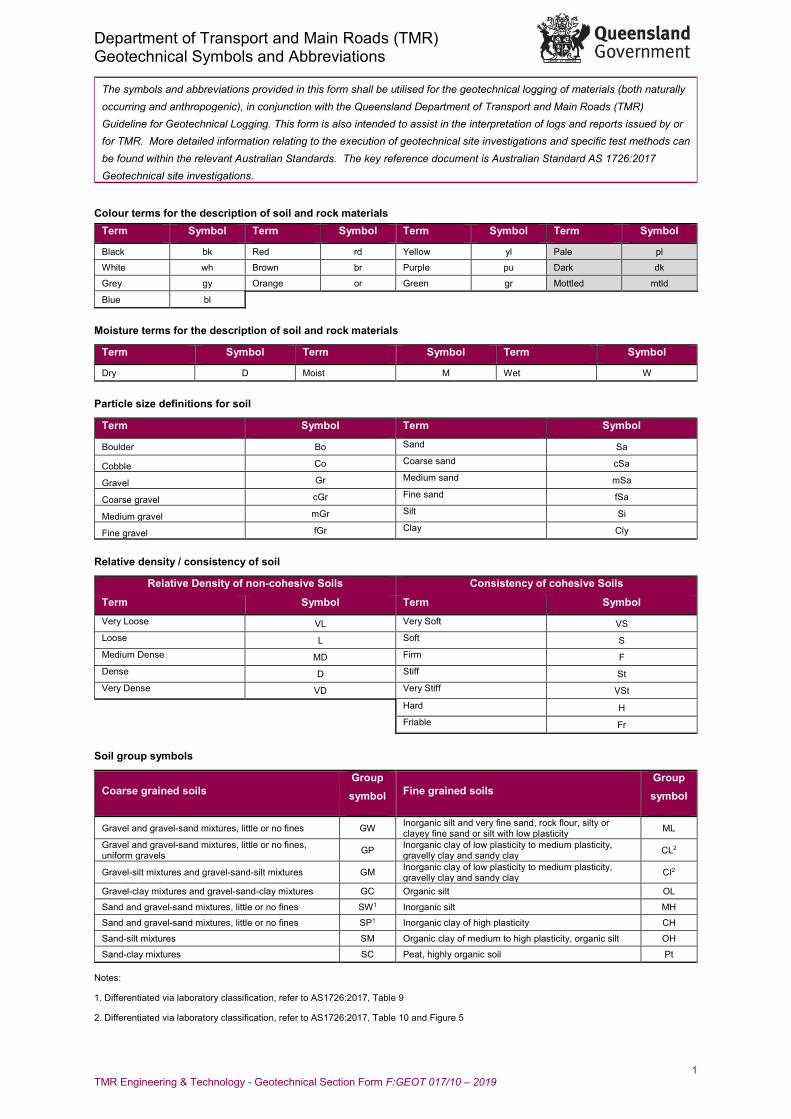
Colour terms for the description of soil and rock materials Term Symbol Term Symbol Term Symbol Term Symbol
Black bk Red rd Yellow yl Pale pl
White wh Brown br Purple pu Dark dk
Grey gy Orange or Green gr Mottled mtld
Blue bl
Moisture terms for the description of soil and rock materials
Term Symbol Term Symbol Term Symbol
Dry D Moist M Wet W
Particle size definitions for soil
Term Symbol Term Symbol
Boulder Bo Sand Sa
Cobble Co Coarse sand cSa
Gravel Gr Medium sand mSa
Coarse gravel cGr Fine sand fSa
Medium gravel mGr Silt Si
Fine gravel fGr Clay Cly
Relative density / consistency of soil
Relative Density of non-cohesive Soils Consistency of cohesive Soils
Term Symbol Term Symbol Very Loose VL Very Soft VS Loose L Soft S Medium Dense MD Firm F Dense D Stiff St Very Dense VD Very Stiff VSt Hard H
Friable Fr
Soil group symbols
Coarse grained soils Group symbol Fine grained soils
Group symbol
Gravel and gravel-sand mixtures, little or no fines GW Inorganic silt and very fine sand, rock flour, silty or clayey fine sand or silt with low plasticity ML
Gravel and gravel-sand mixtures, little or no fines, uniform gravels GP Inorganic clay of low plasticity to medium plasticity,
gravelly clay and sandy clay CL2
Gravel-silt mixtures and gravel-sand-silt mixtures GM Inorganic clay of low plasticity to medium plasticity, gravelly clay and sandy clay CI2
Gravel-clay mixtures and gravel-sand-clay mixtures GC Organic silt OL
Sand and gravel-sand mixtures, little or no fines SW1 Inorganic silt MH
Sand and gravel-sand mixtures, little or no fines SP1 Inorganic clay of high plasticity CH
Sand-silt mixtures SM Organic clay of medium to high plasticity, organic silt OH
Sand-clay mixtures SC Peat, highly organic soil Pt
Notes:
1. Differentiated via laboratory classification, refer to AS1726:2017, Table 9
2. Differentiated via laboratory classification, refer to AS1726:2017, Table 10 and Figure 5
Department of Transport and Main Roads (TMR) Geotechnical Symbols and Abbreviations
2 TMR Engineering & Technology - Geotechnical Section Form F:GEOT 017/10 – 2019
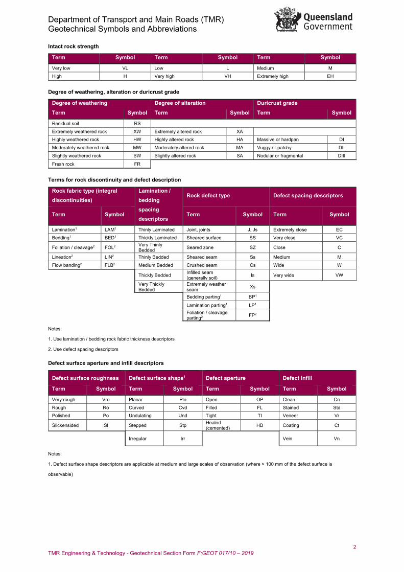
Intact rock strength
Term Symbol Term Symbol Term Symbol
Very low VL Low L Medium M
High H Very high VH Extremely high EH
Degree of weathering, alteration or duricrust grade
Degree of weathering Degree of alteration Duricrust grade
Term Symbol Term Symbol Term Symbol
Residual soil RS
Extremely weathered rock XW Extremely altered rock XA
Highly weathered rock HW Highly altered rock HA Massive or hardpan DI
Moderately weathered rock MW Moderately altered rock MA Vuggy or patchy DII
Slightly weathered rock SW Slightly altered rock SA Nodular or fragmental DIII
Fresh rock FR
Terms for rock discontinuity and defect description
Rock fabric type (integral discontinuities)
Lamination / bedding spacing descriptors
Rock defect type Defect spacing descriptors
Term Symbol Term Symbol Term Symbol
Lamination1 LAM1 Thinly Laminated Joint, joints J, Js Extremely close EC
Bedding1 BED1 Thickly Laminated Sheared surface SS Very close VC
Foliation / cleavage2 FOL2 Very Thinly Bedded Seared zone SZ Close C
Lineation2 LIN2 Thinly Bedded Sheared seam Ss Medium M
Flow banding2 FLB2 Medium Bedded Crushed seam Cs Wide W
Thickly Bedded Infilled seam (generally soil) Is Very wide VW
Very Thickly Bedded
Extremely weather seam Xs
Bedding parting1 BP1
Lamination parting1 LP1 Foliation / cleavage parting2 FP2
Notes:
1. Use lamination / bedding rock fabric thickness descriptors
2. Use defect spacing descriptors
Defect surface aperture and infill descriptors
Defect surface roughness Defect surface shape1 Defect aperture Defect infill
Term Symbol Term Symbol Term Symbol Term Symbol
Very rough Vro Planar Pln Open OP Clean Cn
Rough Ro Curved Cvd Filled FL Stained Std
Polished Po Undulating Und Tight TI Veneer Vr
Slickensided Sl Stepped Stp Healed (cemented) HD Coating Ct
Irregular Irr Vein Vn
Notes:
1. Defect surface shape descriptors are applicable at medium and large scales of observation (where > 100 mm of the defect surface is
observable)
Department of Transport and Main Roads (TMR) Geotechnical Symbols and Abbreviations
3 TMR Engineering & Technology - Geotechnical Section Form F:GEOT 017/10 – 2019
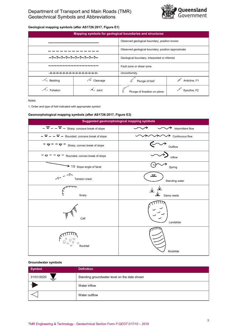
Geological mapping symbols (after AS1726:2017, Figure E1)
Mapping symbols for geological boundaries and structures
___________________ Observed geological boundary, position known
_ _ _ _ _ _ _ _ _ _ _ _ _ Observed geological boundary, position approximate
–?–?–?–?–?–?–?–?–?–?– Geological boundary, interpreted or inferred
~~~~~~~~~~~~~~~~~~ Fault zone or shear zone
–U–U–U–U–U–U–U–U–U–U–U–U–U–U–U– Unconformity
Bedding Cleavage Plunge of fold1 Anticline, F1
Foliation Joint Plunge of lineation on plane Syncline, F2
Notes:
1. Order and type of fold indicated with appropriate symbol
Geomorphological mapping symbols (after AS1726:2017, Figure E3)
Suggested geomorphological mapping symbols
Sharp, concave break of slope Intermittent flow
Rounded, concave break of slope Continuous flow
Sharp, convex break of slope Outflow
Rounded, convex break of slope inflow
Slope angle of facet Spring
Tension crack Standing water
Scarp Damp reeds
Cliff Landslide
Rockfall
Mudslide
Groundwater symbols
Symbol Definition
31/01/2020 Standing groundwater level on the date shown
Water inflow
Water outflow
Department of Transport and Main Roads (TMR) Geotechnical Symbols and Abbreviations
4 TMR Engineering & Technology - Geotechnical Section Form F:GEOT 017/10 – 2019
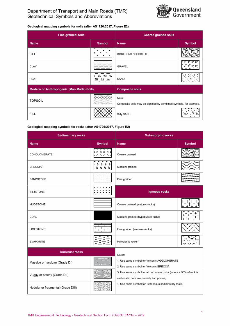
Geological mapping symbols for soils (after AS1726:2017, Figure E2)
Fine grained soils Coarse grained soils
Name Symbol Name Symbol
SILT
BOULDERS / COBBLES
CLAY
GRAVEL
PEAT
SAND
Modern or Anthropogenic (Man Made) Soils Composite soils
TOPSOIL
Note:
Composite soils may be signified by combined symbols, for example,
FILL
Silty SAND
Geological mapping symbols for rocks (after AS1726:2017, Figure E2)
Sedimentary rocks Metamorphic rocks
Name Symbol Name Symbol
CONGLOMERATE1
Coarse grained
BRECCIA2
Medium grained
SANDSTONE
Fine grained
SILTSTONE
Igneous rocks
MUDSTONE
Coarse grained (plutonic rocks)
COAL
Medium grained (hypabyssal rocks)
LIMESTONE3
Fine grained (volcanic rocks)
EVAPORITE
Pyroclastic rocks4
Duricrust rocks Notes:
1. Use same symbol for Volcanic AGGLOMERATE
2. Use same symbol for Volcanic BRECCIA
3. Use same symbol for all carbonate rocks (where > 90% of rock is
carbonate, both low porosity and porous)
4. Use same symbol for Tuffaceous sedimentary rocks.
Massive or hardpan (Grade DI)
Vuggy or patchy (Grade DII)
Nodular or fragmental (Grade DIII)
Department of Transport and Main Roads (TMR) Geotechnical Symbols and Abbreviations
5 TMR Engineering & Technology - Geotechnical Section Form F:GEOT 017/10 – 2019
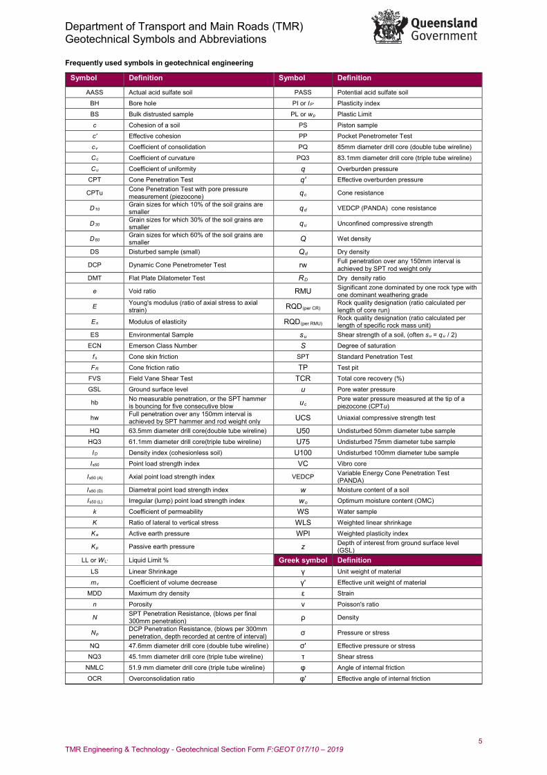
Frequently used symbols in geotechnical engineering
Symbol Definition Symbol Definition
AASS Actual acid sulfate soil PASS Potential acid sulfate soil
BH Bore hole PI or IP' Plasticity index
BS Bulk distrusted sample PL or wp Plastic Limit
c Cohesion of a soil PS Piston sample
c' Effective cohesion PP Pocket Penetrometer Test
cv Coefficient of consolidation PQ 85mm diameter drill core (double tube wireline)
Cc Coefficient of curvature PQ3 83.1mm diameter drill core (triple tube wireline)
Cu Coefficient of uniformity q Overburden pressure
CPT Cone Penetration Test q' Effective overburden pressure
CPTu Cone Penetration Test with pore pressure measurement (piezocone) qc Cone resistance
D10 Grain sizes for which 10% of the soil grains are smaller qd VEDCP (PANDA) cone resistance
D30 Grain sizes for which 30% of the soil grains are smaller qu Unconfined compressive strength
D60 Grain sizes for which 60% of the soil grains are smaller Q Wet density
DS Disturbed sample (small) Qd Dry density
DCP Dynamic Cone Penetrometer Test rw Full penetration over any 150mm interval is achieved by SPT rod weight only
DMT Flat Plate Dilatometer Test RD Dry density ratio
e Void ratio RMU Significant zone dominated by one rock type with one dominant weathering grade
E Young's modulus (ratio of axial stress to axial strain) RQD(per CR) Rock quality designation (ratio calculated per
length of core run)
Es Modulus of elasticity RQD(per RMU) Rock quality designation (ratio calculated per length of specific rock mass unit)
ES Environmental Sample su Shear strength of a soil, (often su = qu / 2)
ECN Emerson Class Number S Degree of saturation
fs Cone skin friction SPT Standard Penetration Test
FR Cone friction ratio TP Test pit
FVS Field Vane Shear Test TCR Total core recovery (%)
GSL Ground surface level u Pore water pressure
hb No measurable penetration, or the SPT hammer is bouncing for five consecutive blow uc Pore water pressure measured at the tip of a
piezocone (CPTu)
hw Full penetration over any 150mm interval is achieved by SPT hammer and rod weight only UCS Uniaxial compressive strength test
HQ 63.5mm diameter drill core(double tube wireline) U50 Undisturbed 50mm diameter tube sample
HQ3 61.1mm diameter drill core(triple tube wireline) U75 Undisturbed 75mm diameter tube sample
ID Density index (cohesionless soil) U100 Undisturbed 100mm diameter tube sample
Is50 Point load strength index VC Vibro core
Is50 (A) Axial point load strength index VEDCP Variable Energy Cone Penetration Test (PANDA)
Is50 (D) Diametral point load strength index w Moisture content of a soil
Is50 (L) Irregular (lump) point load strength index wo Optimum moisture content (OMC)
k Coefficient of permeability WS Water sample
K Ratio of lateral to vertical stress WLS Weighted linear shrinkage
Ka Active earth pressure WPI Weighted plasticity index
Kp Passive earth pressure z Depth of interest from ground surface level (GSL)
LL or WL' Liquid Limit % Greek symbol Definition LS Linear Shrinkage γ Unit weight of material
mv Coefficient of volume decrease γ' Effective unit weight of material
MDD Maximum dry density ε Strain
n Porosity ν Poisson's ratio
N SPT Penetration Resistance, (blows per final 300mm penetration) ρ Density
Np DCP Penetration Resistance, (blows per 300mm penetration, depth recorded at centre of interval) σ Pressure or stress
NQ 47.6mm diameter drill core (double tube wireline) σ' Effective pressure or stress
NQ3 45.1mm diameter drill core (triple tube wireline) τ Shear stress
NMLC 51.9 mm diameter drill core (triple tube wireline) φ Angle of internal friction
OCR Overconsolidation ratio φ' Effective angle of internal friction

![[PPT]Welding Symbols · Web viewWelding Symbols Understanding Welding Symbols Terms and Definitions Plug or Slot Weld Symbol Arrow Side Single-Bevel-Groove and Double Fillet weld Symbols](https://img.pdfslide.us/doc/110x75/5aaa60ff7f8b9a86188df81f/pptwelding-symbols-viewwelding-symbols-understanding-welding-symbols-terms-and.jpg)