Embed Size (px)
Citation preview
Geotechnical Summary US 90 (I-49 South)
Albertsons Parkway to Ambassador Caffrey
Design Build
Stephen E. Greaber, PE
Principal
Senior Geotechnical Engineer
Baton Rouge, LA
PROJECT OVERVIEW
US-90
Frontage Road
Frontage Road
PROJECT OVERVIEW
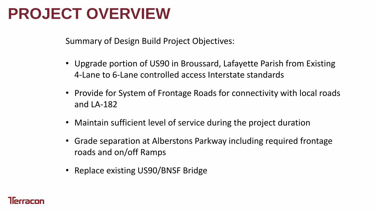
Summary of Design Build Project Objectives: • Upgrade portion of US90 in Broussard, Lafayette Parish from Existing
4-Lane to 6-Lane controlled access Interstate standards
• Provide for System of Frontage Roads for connectivity with local roads and LA-182
• Maintain sufficient level of service during the project duration
• Grade separation at Alberstons Parkway including required frontage roads and on/off Ramps
• Replace existing US90/BNSF Bridge
PROJECT OVERVIEW

PROJECT OVERVIEW
PROJECT OVERVIEW
PROJECT OVERVIEW

MSE Walls
• 4,250 Linear Feet of MSE Wall • Height up to 27 feet
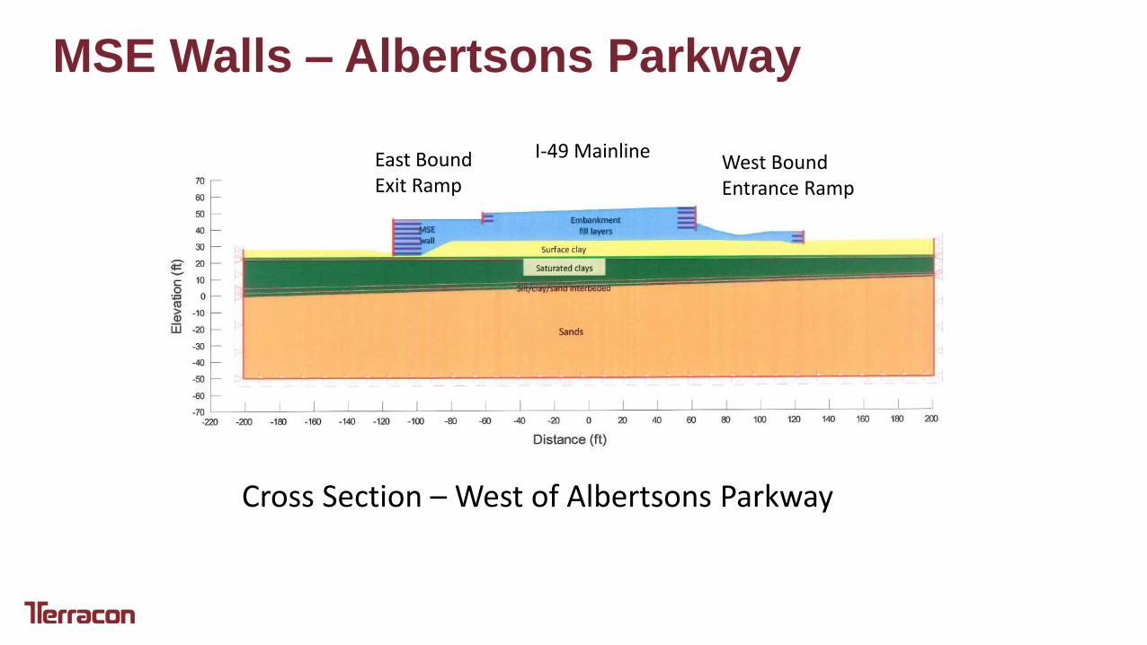
MSE Walls – Albertsons Parkway
Cross Section – West of Albertsons Parkway
East Bound Exit Ramp
I-49 Mainline West Bound Entrance Ramp
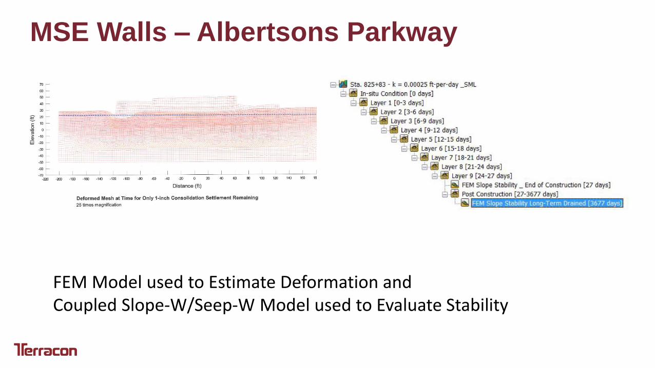
MSE Walls – Albertsons Parkway
FEM Model used to Estimate Deformation and Coupled Slope-W/Seep-W Model used to Evaluate Stability
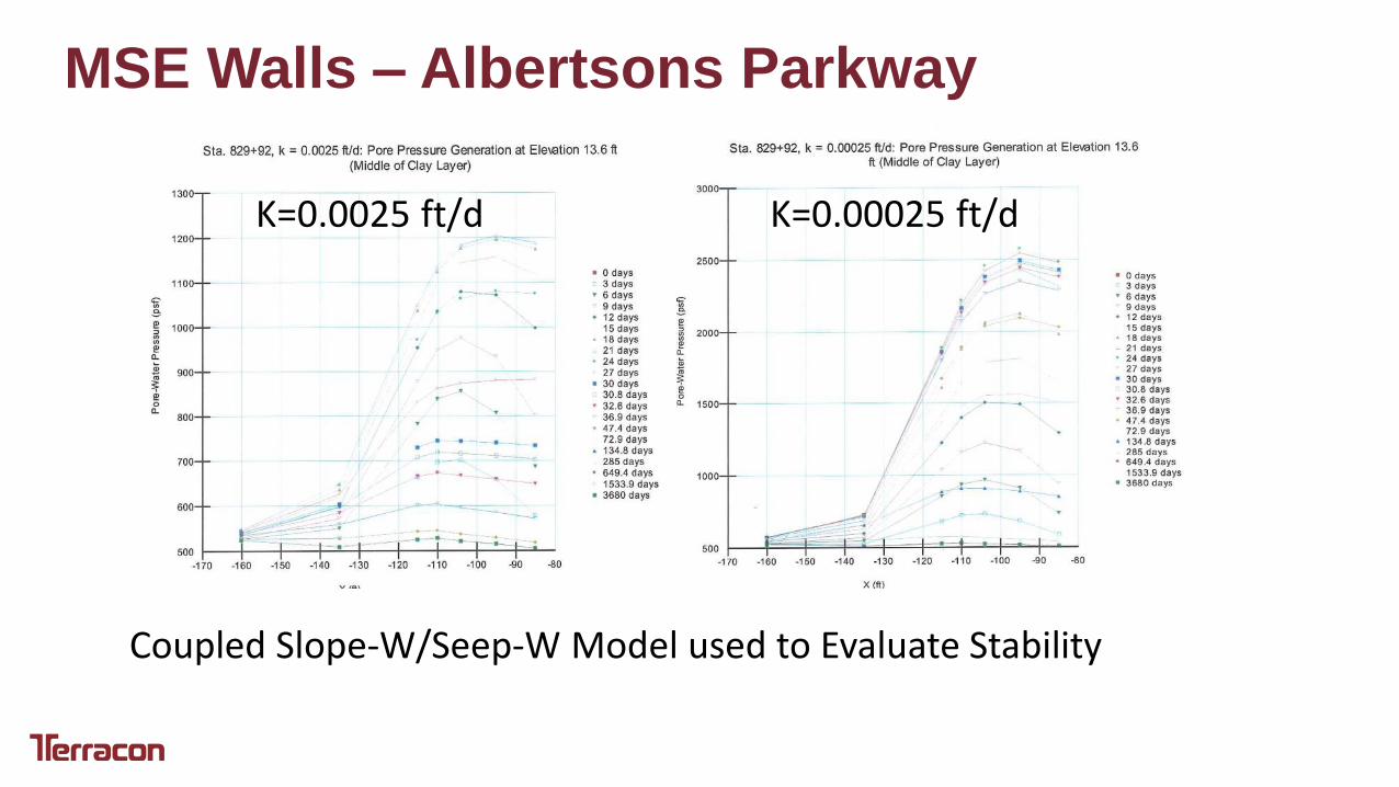
MSE Walls – Albertsons Parkway
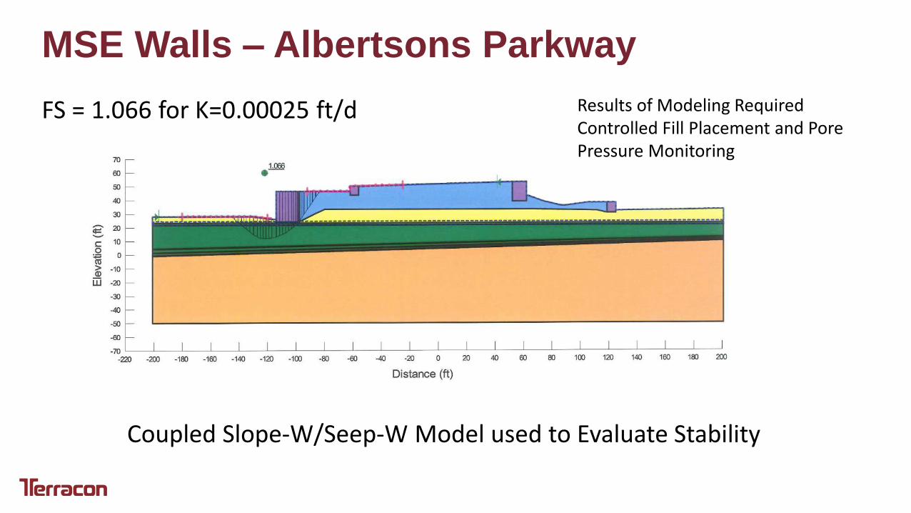
Coupled Slope-W/Seep-W Model used to Evaluate Stability
K=0.0025 ft/d K=0.00025 ft/d
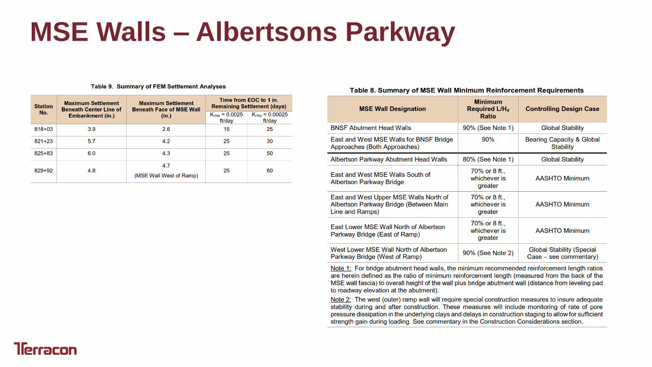
MSE Walls – Albertsons Parkway
MSE Walls – Albertsons Parkway
Coupled Slope-W/Seep-W Model used to Evaluate Stability
FS = 1.066 for K=0.00025 ft/d Results of Modeling Required Controlled Fill Placement and Pore Pressure Monitoring
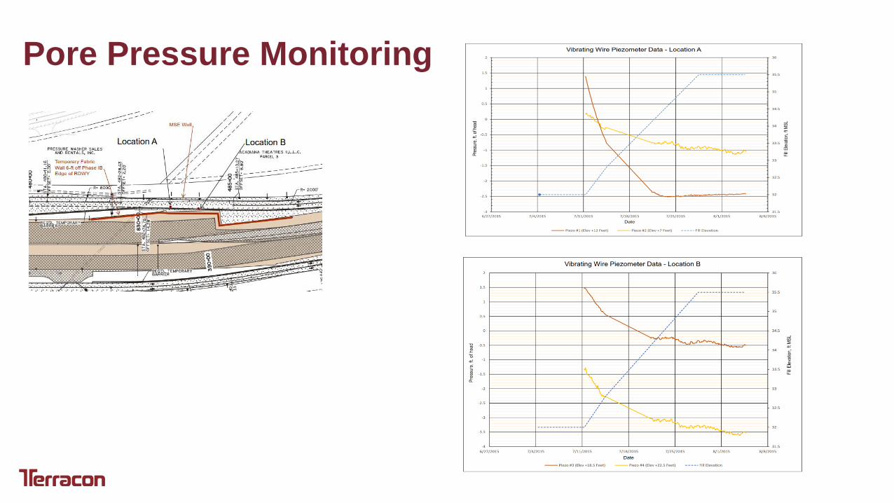
Pore Pressure Monitoring

Temporary Fabric Wrapped Shoring Wall
Needed to Facilitate Construction of MSEW No. 1 – Outer Ramp Wall for Traffic Phasing
Incorporated High Performance Woven Polypropylene Fabric as soil reinforcement and to provide containment of sand fill at wall face.
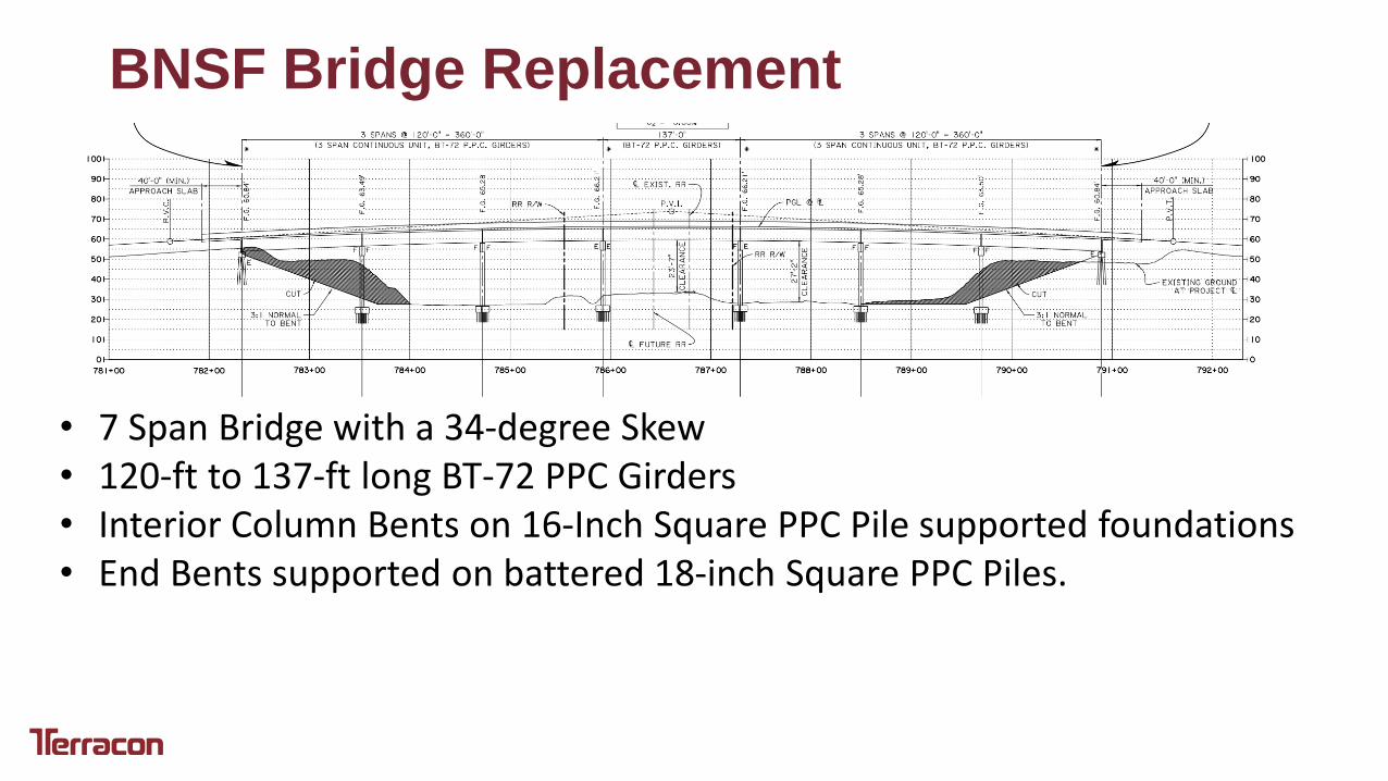
BNSF Bridge Replacement
• 7 Span Bridge with a 34-degree Skew • 120-ft to 137-ft long BT-72 PPC Girders • Interior Column Bents on 16-Inch Square PPC Pile supported foundations • End Bents supported on battered 18-inch Square PPC Piles.
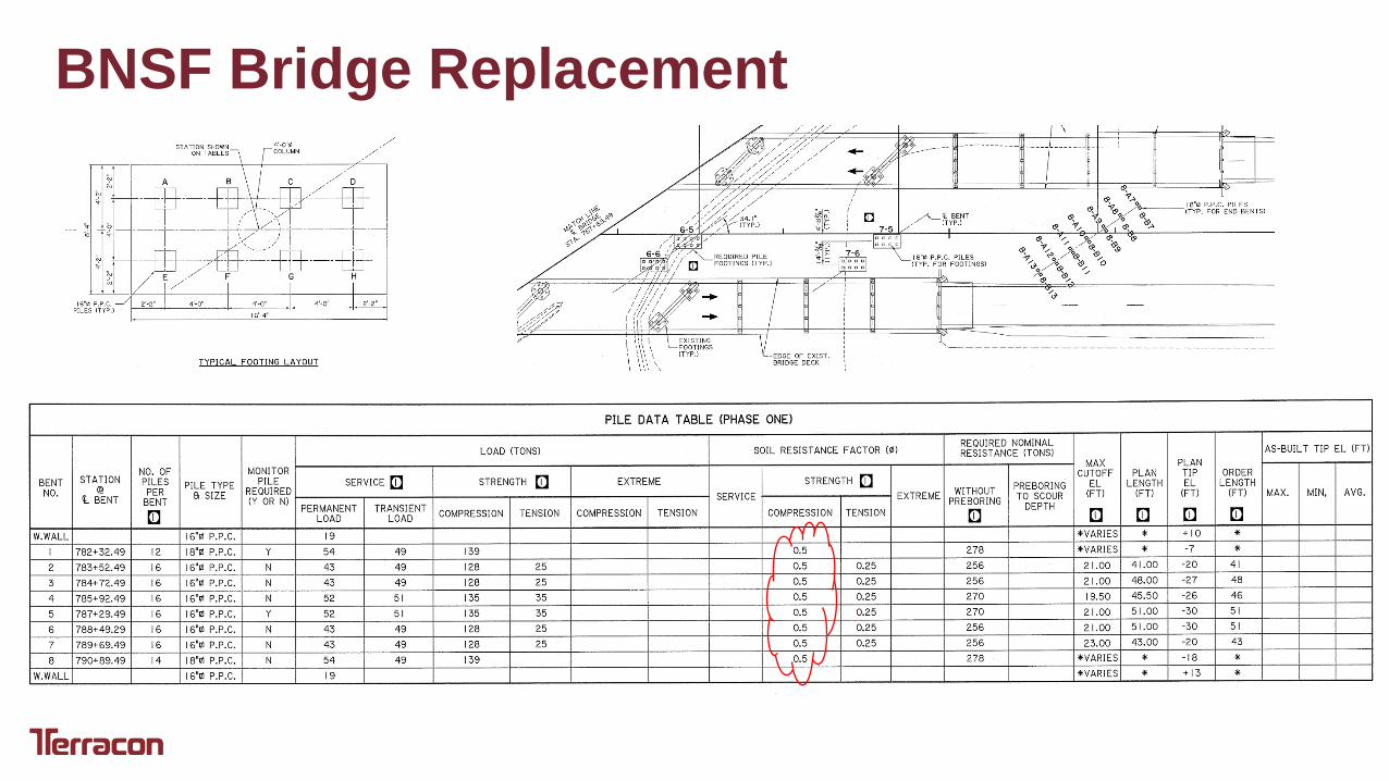
BNSF Bridge Replacement

BNSF Bridge Replacement Geologic Setting
Louisiana Geologic Survey Baton Rouge Quadrangle, 2000
Ppav – Avoyelles Alloformation Meander Deposits of Late Pleistocene Mississippi River. Surface blanketed by Peoria Loess (wind blown deposit laid down during the Wisconsin Ice Age – 17,000 years ago) Soils in this formation are typically lean clays and clays but with some sand layering at depth, are overconsolidated and only marginally compressible.
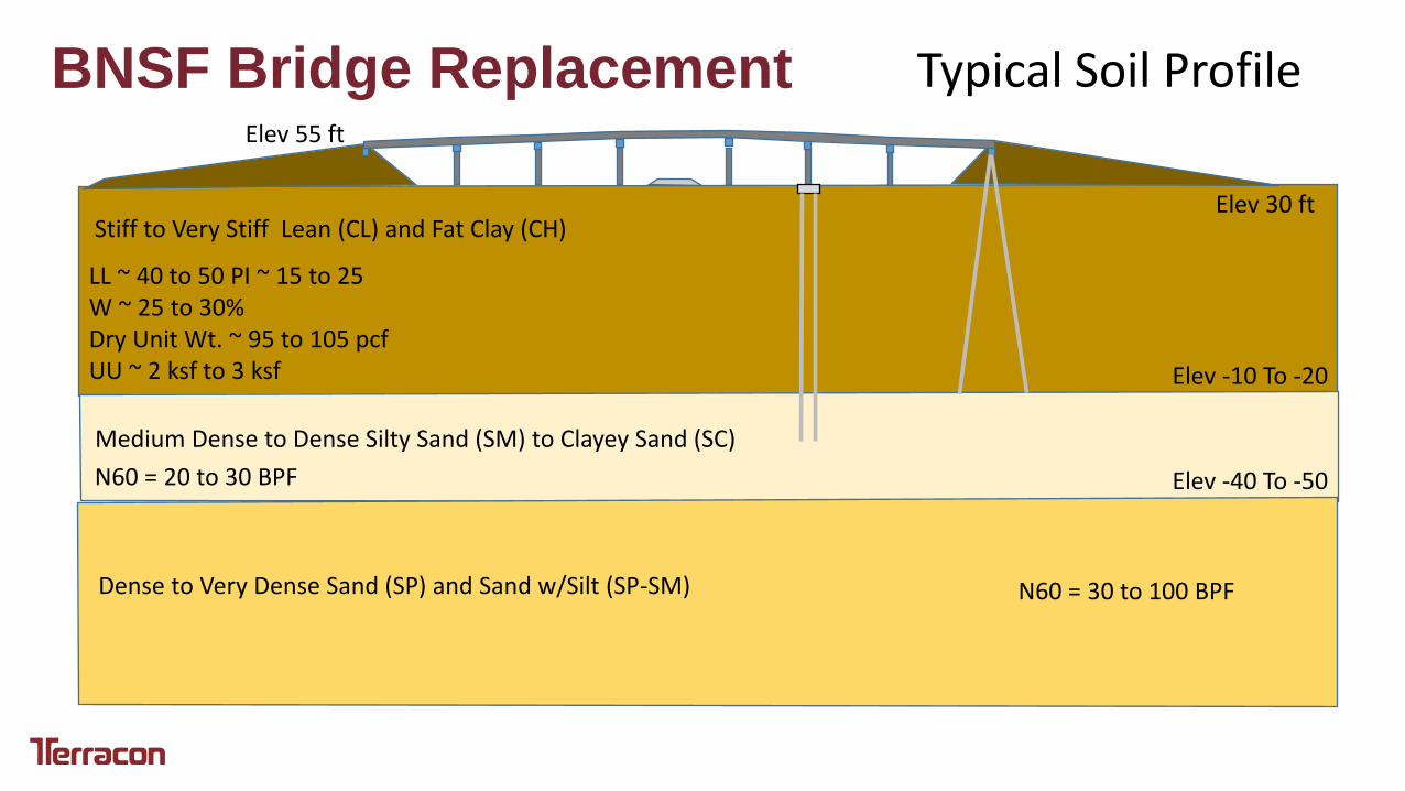
BNSF Bridge Replacement Typical Soil Profile
Stiff to Very Stiff Lean (CL) and Fat Clay (CH) Elev 30 ft
Elev -10 To -20
LL ~ 40 to 50 PI ~ 15 to 25 W ~ 25 to 30% Dry Unit Wt. ~ 95 to 105 pcf UU ~ 2 ksf to 3 ksf
Medium Dense to Dense Silty Sand (SM) to Clayey Sand (SC)
Elev 55 ft
Dense to Very Dense Sand (SP) and Sand w/Silt (SP-SM)
Elev -40 To -50 N60 = 20 to 30 BPF
N60 = 30 to 100 BPF
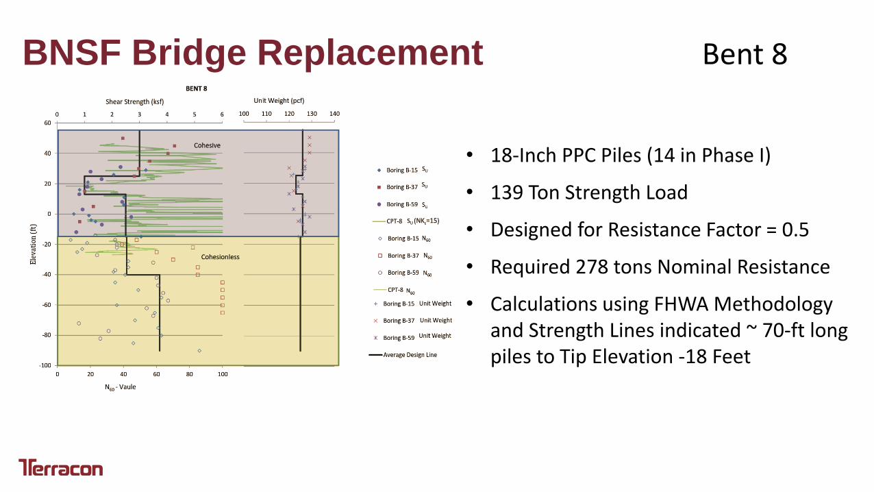
BNSF Bridge Replacement Bent 8
• 18-Inch PPC Piles (14 in Phase I)
• 139 Ton Strength Load
• Designed for Resistance Factor = 0.5
• Required 278 tons Nominal Resistance
• Calculations using FHWA Methodology and Strength Lines indicated ~ 70-ft long piles to Tip Elevation -18 Feet

BNSF Bridge Replacement Bent 8 • Predicted Pile Resistance of around 280 kips
would be present at EOD. Set-up Factor of 2 for clays, tipped in sand.
• WEAP predicted EOD Resistance of 27 BPF.
Not Tipped in Sand?
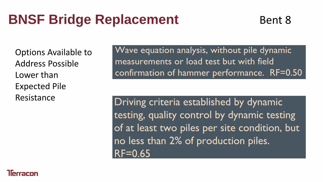
BNSF Bridge Replacement Bent 8
Options Available to Address Possible Lower than Expected Pile Resistance
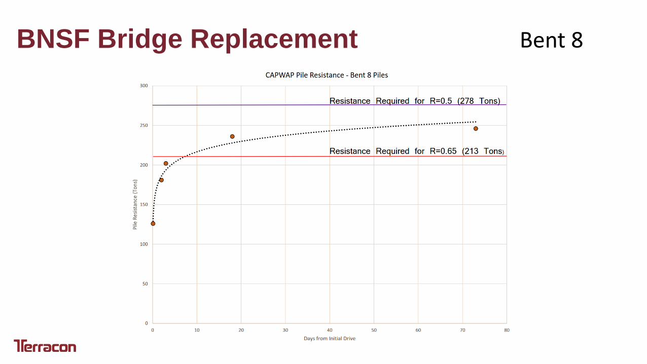
BNSF Bridge Replacement Bent 8