Embed Size (px)
Citation preview

Prepared for:
Wilson & Company, Inc., Engineers and Architects
4401 Masthead St. NE #150, Albuquerque, New Mexico 87109
5/30/2019
Geotechnical Study and Foundation Recommendation
Report
N5012 Sanostee Wash Bridge
Sanostee, New Mexico
Project # 19-517-00007


Geotechnical Study and Foundation
Recommendation Report
N5012 Sanostee Wash Bridge
Project # 19-517-00007
Prepared for:
Wilson & Company, Inc., Engineers and Architects
4401 Masthead St. NE #150, Albuquerque, New Mexico 87109
Prepared by:
Wood Environment and Infrastructure Solutions, Inc.
8501 Jefferson Street NE
Albuquerque, New Mexico 87113
USA
T: 505-821-1801
5/30/2019
Copyright and non-disclosure notice
The contents and layout of this report are subject to copyright owned by Wood (© Wood Environment and Infrastructure
Solutions, Inc.). save to the extent that copyright has been legally assigned by us to another party or is used by Wood under
license. To the extent that we own the copyright in this report, it may not be copied or used without our prior written agreement
for any purpose other than the purpose indicated in this report. The methodology (if any) contained in this report is provided to
you in confidence and must not be disclosed or copied to third parties without the prior written agreement of Wood. Disclosure
of that information may constitute an actionable breach of confidence or may otherwise prejudice our commercial interests. Any
third party who obtains access to this report by any means will, in any event, be subject to the Third Party Disclaimer set out
below.
Third-party disclaimer
Any disclosure of this report to a third party is subject to this disclaimer. The report was prepared by Wood at the instruction of,
and for use by, our client named on the front of the report. It does not in any way constitute advice to any third party who is able
to access it by any means. Wood excludes to the fullest extent lawfully permitted all liability whatsoever for any loss or damage
howsoever arising from reliance on the contents of this report. We do not however exclude our liability (if any) for personal injury
or death resulting from our negligence, for fraud or any other matter in relation to which we cannot legally exclude liability.

Geotechnical Study and Foundation Recommendation Report
N5012 Sanostee Wash Bridge
P a g e | i
TABLE OF CONTENTS
PROJECT SUMMARY.................................................................................................................................................................... 1
1.0 PROJECT DESCRIPTION ............................................................................................................................................. 2
2.0 GEOTECHNICAL PROFILE .......................................................................................................................................... 2
2.1 Geologic Setting .......................................................................................................................................... 2
2.2 Soil Conditions ............................................................................................................................................. 2
2.3 Laboratory Testing ...................................................................................................................................... 2
3.0 SUBSURFACE CONDITIONS ..................................................................................................................................... 3
3.1 Subsurface Exploration ............................................................................................................................. 3
3.2 Subsurface Profiles ..................................................................................................................................... 3
3.2.1 Sanostee Wash Bridge .............................................................................................................. 3
3.2.2 N5012 Roadway Alignment.................................................................................................... 4
3.3 Groundwater and Soil Moisture Conditions ..................................................................................... 5
3.4 Site Seismicity ............................................................................................................................................... 5
4.0 GEOTECHNICAL DESIGN RECOMMENDATIONS............................................................................................. 5
4.1.1 Soils Testing .................................................................................................................................. 5
4.1.2 Soils Chemical Testing .............................................................................................................. 6
4.1.3 Rock Testing ................................................................................................................................. 7
4.2 Geotechnical Foundation Design Parameters ................................................................................. 8
4.3 Pavement Design ........................................................................................................................................ 9
4.3.1 Traffic ............................................................................................................................................... 9
4.3.2 Soil Support .................................................................................................................................. 9
4.3.3 Hot Mix Asphalt Pavement Sections ................................................................................... 9
4.3.4 Chip Seal Recommendations ................................................................................................. 9
4.4 Bridge Foundation Selection ................................................................................................................ 10
4.4.1 Drilled Shafts .............................................................................................................................. 11
5.0 RECOMMENDED ADDITIONAL SERVICES ........................................................................................................ 13
6.0 CLOSURE ....................................................................................................................................................................... 14
TABLES
Table 1 Subsurface Conditions at Abutment 1 (South)
Table 2 Subsurface Conditions at Abutment 2 (North)
Table 3 Seismic Design Parameters
Table 4 R-Values and Soil Classification
Table 5 Chemical Test Results
Table 6 Unconfined Compressive Strength of Rock
Table 7 Geotechnical Design Parameters for Abutment 1 (South)
Table 8 Geotechnical Design Parameters for Abutment 2 (North)
Table 9 Hot Mix Asphalt Pavement Sections
Table 10 Chip Seal Pavement Sections
Table 11 Drilled Shaft Geotechnical Resistance Summary
Table 12 Drilled Shaft Load Transfer Settlement
Table 13 Recommended Soil Geotechnical Properties for Lateral Analysis at Abutment 1
Table 14 Recommended Soil Geotechnical Properties for Lateral Analysis at Abutment 2

Geotechnical Study and Foundation Recommendation Report
N5012 Sanostee Wash Bridge
P a g e | ii
FIGURES
Figure 1 Site and Exploration Plan
Figure 2 Estimated Axial Capacity (Abutment #1 South)
Figure 3 Estimated Axial Capacity (Abutment #2 North)
APPENDICES
Appendix A Field Exploration Procedures and Logs
Appendix B Laboratory Testing Procedures and Results

Geotechnical Study and Foundation Recommendation Report
N5012 Sanostee Wash Bridge
P a g e | 1
PROJECT SUMMARY
Wood Environment & Infrastructure Solutions (Wood E&IS) is providing geotechnical engineering
support for the N5012 Sanostee Wash Bridge Improvement project. N5012 is planned to be re-routed
around the town of Sanostee to provide access to the proposed crossing. The beginning of project
(BOP) is defined at Station 0+00, approximately at the intersection of the proposed location of N5012
and N34. The planned bridge for Navajo Division of Transportation (NDOT) Route N5012 is located at
approximately station 46+00. The end of project (EOP) is located at Station 74+56, approximately ½
mile north of the proposed bridge, and along the existing route N5012. Refer to Figure 1 for the Site
Map. The Navajo Division of Transportation has commissioned Wilson & Company to provide design
engineering for improvements to the existing N5012 alignment, Design of the Sanostee Wash bridge,
and Design of a new alignment south of the proposed bridge to provide access while by-passing the
town of Sanostee. Wood is supporting the Wilson & Company team with geotechnical and foundation
design support.
This Report presents data and data interpretation including:
discussions of the terrain and geologic features at the project site;
discussion of subsurface conditions based on the field investigations, and drilling
summary sheets;
pavement design and construction recommendations; and
foundation selection for N5012 Wash Bridge and design recommendations
Foundation design recommendations presented in this report are specific to the construction of the
Sanostee Wash Bridge. Recommendations for retaining walls are also provided in this report.
Applicable standards include the 2014 edition of The Standard Specifications for Construction of
Roads and Bridges on Federal Highway Projects and the 8th Edition, 2017 AASHTO LRFD Bridge
Design Specification in U.S. Customary Units.
Subsurface conditions underlying the proposed bridge location are considered to be fairly consistent
with sand, gravel, and cobbles in the upper 10’ to 20’. Weathered shale bedrock is encountered
nominally 50’ below the top of existing embankment at the crossing. The rock is observed to vary
in quality fairly significantly between the explored depths of 45’ and 75’ below the surface. The
proposed bridge is recommended to be supported using deep foundations. Geotechnical issues with
construction of deep foundations at the site include groundwater conditions, obstructions while
driving piles or drilling shafts, and excavation instability.
There is a risk working near the Sanostee Wash of varying seasonal groundwater at the site. The
Contractor should anticipate groundwater and anticipate using the casing construction method or
slurry-displacement if the dry construction method is inadequate to prevent sidewall caving conditions.
foundation selection for N5012 Wash Bridge and design recommendations

Geotechnical Study and Foundation Recommendation Report
N5012 Sanostee Wash Bridge
P a g e | 2
1.0 PROJECT DESCRIPTION
N5012 Sanostee Wash Bridge project is located in Sanostee, New Mexico. The proposed bridge will
replace a previously constructed embankment which has since been washed away. The original
embankment was constructed with large corrugated metal culverts to provide means of seasonal
surface water flow to pass beneath the crossing. It is proposed that a new bridge be constructed bearing
on stabilized portions of the remaining embankment on each side each side of the wash.
This project includes 1.41 miles of roadway realignment, cut/fill, replacing culverts, installing new
culverts, grades and drain improvements, and paving along with the construction of the new bridge.
This report provides preliminary recommendations for paving and the construction of the new bridge
at station 46+00.
2.0 GEOTECHNICAL PROFILE
The following sections of text present our observations, measurements, and interpretations regarding
surface, soil, and groundwater at the project site.
2.1 Geologic Setting
According to published geologic maps (Geologic map of New Mexico, 2003), soil and rock conditions
in the site vicinity are characterized by Holocene-aged and/or Pleistocene-aged Quaternary alluvial and
eolian deposit, and Upper Cretaceous-aged sandstone. The Quaternary deposits are comprised of
alluvial deposits and windblown silt and sand deposits. The native soils encountered during the
subsurface exploration at the bridge site consist primarily of coarse-grained soil mixtures of clay, silt,
sand, gravel and occasional cobbles overlaying bedrock. The sandstone typically is fine-grained and
gray with lamination. The exploration logs (enclosed in Appendix A) provide a detailed description of
the soil strata encountered in our subsurface explorations.
2.2 Soil Conditions
Unconsolidated granular alluvial soils were encountered at the ground surface overlying claystone and
black shale. The soils comprised mixtures of silt, sand and gravel with the percent of gravel increasing
with boring depth. The boring was terminated at 70 feet due to auger refusal. Rock coring was
performed in two locations (B-09 and B-10) to examine the condition of the in-place rock between
4/29/2019-5/4/2019. Location B-08 was terminated at the depth bedrock was encountered. Location B-
11 was performed on February 25, 2019 and advanced through approximately 20 feet of bedrock. Samples
of the rock at B-11 were not retrieved due to pulverization of the samples caused by boring.
2.3 Laboratory Testing
Laboratory tests were performed on the representative split spoon samples obtained during our
subsurface exploration to evaluate and characterize the site soils for the engineering design and
analysis. The following tests were performed in general accordance with applicable America Association
of State Highway and Transportation Office (AASHTO) test methods. In absences of an AASHTO test
method, ASTM methods were used.
Sieve Analysis
Moisture
Plasticity Index
Direct Shear Test
Unconfined Compressive Strength of Rock (yet to be conducted)

Geotechnical Study and Foundation Recommendation Report
N5012 Sanostee Wash Bridge
P a g e | 3
R-Value
Sulfate and chloride content, pH, and resistivity
3.0 SUBSURFACE CONDITIONS
3.1 Subsurface Exploration
The initial surface and subsurface exploration for this project was performed from February 25 to
February 27, 2019. Field direction, sample collection and logging of boring were performed by Jacob
Hays, PE of Wood E&IS. Because rock was encountered and the drilling subcontractor did not have the
ability to perform rock coring, a later site visit was performed to core and sample the rock to assist in
determining quality and strength. Logs of all borings are presented in Appendix A of this report. The
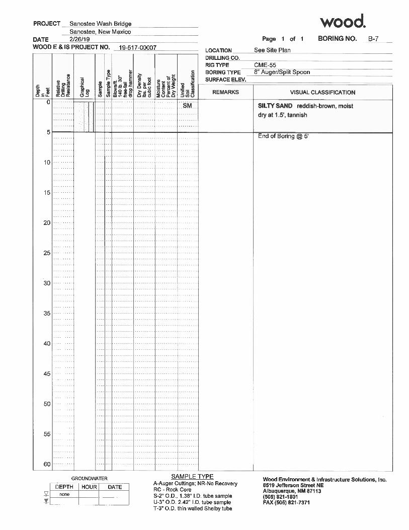
deep borings, B-08, B-09, B-10, and B-11, encountered bedrock at 45-50 feet.
The second site visit to complete rock coring operations was completed May 4, 2019 by Greg Davies,
EIT. Rock coring was performed at locations B-09 and B-10 to depths of 15 to 30 feet beyond the depth
for which rock is encountered in two of the locations. Figure 1 shows the site vicinity and the boring
location maps respectively.
Boring B-11 was completed by Geomat with a truck -mounted CME-55 drill rig utilizing a continuous
flight hollow-stem auger. Boring was performed at location B-11 to a depth of 70 feet. Rock was
encountered at B-11 at a depth of 45 feet. The boring was advanced through rock using the auger and
blow counts were performed at intervals of 5 feet to evaluate whether the boring had encountered bed
rock, boulders, or cemented soils. It was determined that the materials encountered at depths between 45
and 70 feet at B-11 were bedrock and that it would be necessary to re-visit the site to collect core samples
of the bedrock at a later date.
B-08, B-09, and B-10 were performed by Enviro-drill with a truck -mounted CME-75 drill rig utilizing a
continuous flight hollow-stem auger and split barrel coring bits. In addition, visual surface reconnaissance
of the site was also conducted.
The specific locations, and depths of our borings were selected by Wood E&IS and Wilson & Company,
Inc., Engineers and Architects, and field-adjusted based on existing site features, under the constraints
of surface access, underground utility locations, and budget considerations. We estimated the relative
location of each exploration by measuring from existing features and scaling these measurements onto
a layout plan supplied to us, and then we estimated their elevations by interpolating between contour
lines shown on this same plan. Consequently, the data listed in Table 1 and the locations depicted on
figures should be considered accurate only to the degree permitted by our data sources and implied by
our measuring methods.
It should be noted that the explorations performed and used for this report reveal subsurface conditions
only at discrete locations along the project alignments and that actual conditions in other locations
could vary. Furthermore, the nature and extent of these variations would not become evident until
additional explorations are performed or until construction activities have begun. If significant variations
are observed at that time, we may need to modify our conclusions and recommendations contained in
this report to reflect the actual site conditions.
3.2 Subsurface Profiles
3.2.1 Sanostee Wash Bridge
Subsurface conditions at the proposed locations of Abutment 1 (South) were evaluated based on boring
B-08 and B-09. Subsurface conditions at the proposed locations of Abutment 2 (North) were evaluated
based on boring B-10 and B-11. The borings were positioned on top of the existing embankment and
on each side of the abutments. The soils beneath the top of the embankment are granular with varying

Geotechnical Study and Foundation Recommendation Report
N5012 Sanostee Wash Bridge
P a g e | 4
amounts of silt, gravel, and cobble. These soils extend to approximately 45 feet and can be described as
medium dense to very dense. Weathered Mancos Shale Bedrock is encountered at a depth of 50’ below
the surface for Abutment 1 (South), and 45’ below the surface for Abutment 2 (North).
A generalized subsurface profile was developed using these borings for the abutments (Abutments 1 and
2). It is recognized that soil properties vary within short horizontal and vertical deviations from the
locations drilled. Tables 1 and 2 present a profile of the subsurface conditions for Abutments 1 and 2,
respectively.
Table 1: Subsurface Conditions at Abutment 1 (South)
Description of Soil Unit (1) Estimated Top
Elevation (feet)
Estimated
Thickness
(feet)
Typical Soil
Type(s)
Soil Unit A: medium dense silty sand with
gravel.
5923’ 5 SW, SM
Soil Unit B: medium dense to dense sand
with gravel and cobble.
5918’ 30 SM, SP, SW
Soil Unit C: Loose to medium dense clean
sand.
5888’ 5 SP
Soil Unit D: Silty sand, low plasticity clay 5883’ 10 SM, SC
Soil Unit E: Weathered Mancos Shale
Bedrock/Claystone
5873’ Unknown(2) Bedrock
(1) Geotechnical staff used field moisture, SPT values and laboratory results to profile the subunits. (2) Rock coring was performed and extended 18’ into bedrock during the week of April 29, 2019
Table 2: Subsurface Conditions at Abutment 2 (North)
Description of Soil Unit (1) Estimated Top
Elevation (feet)
Estimated
Thickness
(feet)
Typical Soil
Type(s)
Soil Unit A: medium dense silty sand with
gravel.
5923’ 5 SW, SM
Soil Unit B: medium dense to dense sand
with gravel and cobble.
5918’ 25 SM, SP, SW
Soil Unit C: Loose to medium dense clean
sand.
5893’ 5 SP
Soil Unit D: Silty sand, low plasticity clay 5888’ 10 SM, SC
Soil Unit E: Weathered Mancos Shale
Bedrock/Claystone
5878’ Unknown(2) Bedrock
(1) Geotechnical staff used field moisture, SPT values and laboratory results to profile the subunits. (2) Rock coring was performed and extended 25’ into bedrock during the week of April 29, 2019
3.2.2 N5012 Roadway Alignment
Subsurface conditions between stations 0+00 to 21+00 are predominately clayey. The portion of N5012
north of the bridge site is also considered to be clayey based on the field investigation and the

Geotechnical Study and Foundation Recommendation Report
N5012 Sanostee Wash Bridge
P a g e | 5
laboratory results. A significant portion along the alignment between stations 21+00 and 52+00 are
more granular within the upper 5 feet observed.
Dynamic Cone Penetrometer testing near station 21+00 was performed to evaluate potential for
settlement of large corrugated metal structures to a depth of 10 feet. It was determined that the
subgrade soils are granular with some silt and clay, and are typically medium dense. A maximum
allowable bearing capacity of 2000 pounds per square foot would be recommended for use in design
of embankments and culverts for this project.
3.3 Groundwater and Soil Moisture Conditions
At the time of the original drilling (February 25, 2019), the groundwater was encountered at about 24
feet below the top of existing embankment at boring B-11. The next visit (April 29, 2019), groundwater
was encountered at about 25, 24, and 19 feet below the top of existing embankment at borings B-08,
B-09, and B-10 respectively. Moisture content of the soil above the water table was determined and
used to evaluate the on-site soil moisture characteristics. The site soils above the groundwater surface
were generally described as dry to moist with moisture content varying from 2 to 18%.
Seasonal variations could cause fluctuations in groundwater depth and depth to groundwater could be
shallower or deeper than indicated this report.
3.4 Site Seismicity
Seismic design parameters at the project location for peak horizontal acceleration and the horizontal
spectral response acceleration of 1.0-second duration with a 7-percent probability of exceedance during a
75-year period are presented below in table 3. The site class design parameters recommended for the
project are based on subsurface investigations at the site.
Table 3: Seismic Design Parameters
Design Parameter Value AASHTO Reference
(2014)
Peak Ground Acceleration Coefficient (PGA) 0.046 Figure 3.10.2.1-1
Acceleration Coefficient, Ss 0.110 Figure 3.10.2.1-2
Acceleration Coefficient, Sl 0.030 Figure 3.10.2.1-3
Acceleration Coefficient, SDS 0.176 Eq. 3.10.4.2-3
Acceleration Coefficient, SD1 0.072 Eq. 3.10.4.2-6
Site Class D Table 3.10.3.1-1
As 0.074 Eq. 3.10.4.2-2
Abbreviations
g = Acceleration due to gravity
PGAm = Site peak ground acceleration
4.0 GEOTECHNICAL DESIGN RECOMMENDATIONS
The following sections provide information on the recommended foundation types for the proposed
bridge structure and pavement design.
4.1.1 Soils Testing
Seventeen AASHTO/ASTM soil classification and four R-value tests were performed on surface soils
along the alignment. Results are presented in the table below:

Geotechnical Study and Foundation Recommendation Report
N5012 Sanostee Wash Bridge
P a g e | 6
Table 4: R-Values and Soil Classification
Boring No. Depth
(feet)
R-value(1) ATSM
Classification(2)
AASHTO
Classification
B-1 0.0-5.0’
2
CH A-7-6
B-2 0.0-5.0’ CH A-7-6
B-3 0.0-5.0’ CH A-7-6
B-4 0.0-5.0’ 18
SM A-6
B-5 0.0-5.0’ CL A-6
B-6 0.0-5.0’
41
SM A-6
B-7 0.0-5.0’ SM A-2-4
B-16 0.0-5.0’ SM A-4
B-12 0.0-5.0’ SM A-4
B-13 0.0-5.0’
3
CL A-6
B-14 0.0-5.0’ CL A-6
B-15 0.0-5.0’ CL A-6
Notes: (1) R-values performed on combined samples as indicated
(2) As classified in the field
4.1.2 Soils Chemical Testing
Tests for pH (AASHTO T289), Sulfate Content (AASTHO T290), Chloride Content (AASHTO T291), and
Resistivity testing (AASHTO T-288) are presented below. The tests performed for this study were
included as per The Federal Highway Administration’s Geotechnical Technical Guidance Memo.
Table 5 Chemical Test Results
S.U. = Standard Unit; ppm = part per million
The sulfate test result for the sample representing soils at the bridge were 152 ppm, and indicates that
the Exposure Class has “Negligible” potential for sulfate reaction with the concrete. The cement type
required for “Negligible” Exposure Class is ASTM C150 Type I Cement. It would be recommended to
select a Type II.
Boring Soil Type
Sample
Depth, ft pH (S.U.)
Sulfate
Content
(ppm)
Chloride
Content
(ppm)
B-6, B-7,
B-12,
and B-16
Silty Sand 0’-5’ 8.3 563 33
B-13, B-
14, and
B-15
Clayey sand 0’-5’ 8.1 1255 33
B-11 Sand with natural
gravel/cobble
25’-26.5’ 8.9 152 11

Geotechnical Study and Foundation Recommendation Report
N5012 Sanostee Wash Bridge
P a g e | 7
Laboratory test results indicate that the onsite soils for the project have pH values ranging from 8.1 to
8.9 and Chloride content between 11 and 33 ppm.
Corrosion of metals is an electrochemical process which involves oxidation and reduction reactions on
metal surfaces. For metals in soils and water, corrosion is typically a result of contact with soluble salts
or an acidic (pH of 4.5 or less) environment. Per FHWA recommendations, the maximum range for the
“Moderately Corrosive Range” (Resistivity from 5000 to 2000 ohm-cm) is 100 ppm for chloride ions and
200 ppm for sulfates. The tested chloride content (11-33 ppm) in all samples is lower than the
recommended limit, but the sulfates (152 – 1255) are much higher than FHWA limits. The measurement
of pH on the soil samples shows that the soils are alkaline. Very strong alkalinity soils (pH greater than
10) are generally associated with significant corrosion rates. None of the pH tests for the bridge and
have pH values greater than 10.
Given all of the corrosivity data available, it is our opinion that the soils present at the project are
potentially corrosive given the sulfate content and pH level. Resistivity testing was performed onsite
and it was concluded that the resistivity of soils for abutment 1 (south) were on average 6176 Ohm-cm,
and 11227 Ohm-m. This suggests that the onsite soils near the bridge are “Mildly Corrosive” to “Non-
Corrosive” per FHWA aggressiveness criteria. Other Resistivity testing was performed near station
24+00 to evaluate corrosivity near proposed corrugated metal culverts. The results at station 24+00
were 7580 Ohm-cm on average, which also places the soils in the “Mildly Corrosive” aggressiveness
category.
Samples of site soil was submitted for sulfate content to evaluate potential for lime treating onsite soils
for fill and pavement design purposes. The highest result was 1255 ppm. Generally, the upper limit
permitted for lime treating soils is 3,000 ppm. Given that the result is less than the upper limit
recommended, it appears that lime treatment of the site soils is feasible. Given that the result of 1255
ppm is relatively close to the upper limit it will be recommended to allow lime/soil mixtures to “mellow”
for a period of 48 hours prior to final fill placement as recommended FHWA/TX-06/0-4240-3
“Recommendations for Stabilization of High Sulfate in Soils.”
4.1.3 Rock Testing
It was necessary to quantify the properties of the rock mass encountered to make recommendations
for end bearing (tip resistance). AASHTO 2014 Sections 10.8.3.5.4c-1 and 10.8.3.5.4b were reviewed and
utilized to quantify the properties of the rock. A GSI of 35 and RQD of 26% were derived using the
“Quantification of the Geological Strength Index chart” by E. Hoek, et al. Unconfined compressive
testing was performed on select samples using ASTM D7012. Results of unconfined compression
testing are shown below. It can be observed that the results are highly variable. Not all of the tests are
considered to be representative due to sample disturbance during removal from core drill in the field
and drying shrinkage during specimen transport. A representative value of 2400 psi was utilized for
unconfined compressive strength of the rock deposit given the data and our experience with the shales
present in this part of the state.

Geotechnical Study and Foundation Recommendation Report
N5012 Sanostee Wash Bridge
P a g e | 8
Table 6: Unconfined Compressive Strength of Rock
Boring No. Depth
(feet)
Density
(lbs/cu. ft)
Unconfined
Compressive
Strength (psi)
B-9 55 124 181
B-10 63 157 7907
B-10 67 150 2419
B-10 69 114 45
4.2 Geotechnical Foundation Design Parameters
Geotechnical design parameters for the project were derived from interpreted soil boundaries,
samples collected and described in the field, SPT testing, laboratory testing, correlations with
AASHTO design charts, and past project experience. The soil parameters, presented in Tables 7
and 8, are site-specific values developed for use in the foundation design calculations.
Table 7: Geotechnical Design Parameters for Abutment 1 (South)
Design Soil Parameter Soil Unit
A
Soil Unit
B
Soil Unit
C
Soil Unit
D
Soil Unit
E
N60 Value 13-41 18-42 7 50 100+
Friction angle Φ,
degrees
22 30 -- -- --
Cohesion, c, psf 246 0 -- -- --
Estimated Moist Unit
Weight, γm, pcf
120-123 123-143 120 115 150
Uniaxial Compressive
Strength, qu, psi
-- -- -- -- 2400
Table 8: Geotechnical Design Parameters for Abutment 2 (North)
Design Soil Parameter Soil Unit
A
Soil Unit
B
Soil Unit
C
Soil Unit
D
Soil Unit
E
N60 Value 13-41 18-42 7 50 100+
Friction angle Φ,
degrees
22 30 -- -- --
Cohesion, c, psf 246 0 -- -- --
Estimated Moist Unit
Weight, γm, pcf
120-123 123-143 120 115 150
Uniaxial Compressive
Strength, qu, psi
-- -- -- -- 2400

Geotechnical Study and Foundation Recommendation Report
N5012 Sanostee Wash Bridge
P a g e | 9
4.3 Pavement Design
In accordance with the Federal Lands Highway Project Development and Design Manual, pavement
design has been performed to support the proposed alignment for N5012. Structural pavement
thickness design was performed using the AASHTO ’93 method.
4.3.1 Traffic
The FHWA requires a minimum of 50,000 ESALs for consideration in the design of newly paved
surfaces. Average Daily Traffic (ADT) was determined to be 334 vehicles per day for year 2013 and
projected to be 496 vehicles per day for year 2033. Truck/vehicle percentages were not included in the
referenced ADT summary. Given the minimum required ESAL’s of 50,000 and the provided ADT data,
the total ESAL’s for the roadway will be less than the minimum required considering a growth rate less
than 2.1% and a vehicle distribution of 99% personally operated vehicles, and 1% of mixed tuck traffic
with an average ESAL Factor of 1.14.
4.3.2 Soil Support
Based on the results of the study, the soils between stations 0+00 to 21+00 are predominately clayey
with an R-value of 2. The portion of N5012 north of the bridge site is also considered to be clayey based
on the field investigation and has similar R-Value laboratory results. The soils between stations 21+00
and 52+00 were observed to be more granular and samples tested resulted in an R-Value of 18. Two
soil support conditions were modeled for providing these recommendations. Soil Support A represents
the soil conditions between Stations 21+00 and 52+00 with a Resilient Modulus (Mr) 7,000 psi using
Mechanistic and Empirical Design Correlations (MEPDG). Soil support B represents the clayey portions
of the project alignment, and was modeled using a resilient modulus of 2,500 psi.
4.3.3 Hot Mix Asphalt Pavement Sections
As required by the FHWA design manual, a reliability of 75%, combined standard error of 0.49, initial
serviceability index of 4.2, and final serviceability index of 2.0 was used for calculating allowable ESALs.
This analysis did not consider frost/heave susceptibility of subgrade. The analysis resulted in
recommended structural numbers of 2.0 for Soil Support A, and 2.9 for Soil Support B. The table
below provides possible thickness design for both Soil Support A and B using layer coefficients for
treated soils, unbound granular base course, and hot mix asphalt as 0.08/inch, 0.10/inch, and 0.40/inch
respectively.
Table 9: Hot Mix Asphalt Pavement Sections
Pavement Section/Soil Support A B
HMA (Item FP-401) 3.5" 3.5"
BC (Item FP-301) 6" 6"
Treated Subgrade (per FP-14 specifications) 0" 12"
Subgrade (Item FP-204) 12" 6"
*HMA = Hot Mix Asphalt (superpave), BC = Unbound Aggregate
Base Course
4.3.4 Chip Seal Recommendations
In lieu of paving with hot mix asphalt, a “Double Course Chip Seal” may be utilized as a surfacing
material. The FHWA does not provide period of performance requirements for preventative
maintenance projects such as chip seal. FP14-Specification Section 407 “Chip Seal” requires placement

Geotechnical Study and Foundation Recommendation Report
N5012 Sanostee Wash Bridge
P a g e | 10
of chip seal over either new asphalt patch areas, existing asphalt surfaces (including recycled asphalt
pavements), or aggregate base course surfaces. For this project, it would be recommended to place a
layer of aggregate base course material over prepared subgrade on the existing unsurfaced roadway
prior to chip sealing operations.
If it is not desired to provide a section meeting the structural design requirements for unsurfaced gravel
roads as recommended in the following paragraphs, it is recommended to place a minimum of 6” of
aggregate base course over the prepared subgrade for chip seal placement.
The FHWA does provide a period of performance of five to ten years for aggregate surfaced roads. The
recommended thickness of aggregate base course to be placed under the chip seal surfacing will
consider the minimum ESAL’s required by the FHWA for gravel road. The minimum number of ESAL’s
for Gravel Surfaced Roads for FHWA projects is 10,000.
The proposed area to be chip sealed includes the portion of roadway north of the bridge. A combined
sample of the borings performed north of the bridge (B-13, B-14, and B-15) was tested for soil support
characteristics. The combined sample was determined to have an R-Value of 3. This roughly
corresponds to a resilient modulus of 3,000 psi.
Given this analysis, a structural number of 2.1 is recommended for the pavement section beneath chip
seal to meet the minimum traffic requirement of the FHWA. Potential pavement sections meeting this
are shown below:
Table 10: Chip Seal Pavement Sections
Pavement Section Option 1 Option 2 Option 3
Double Course Chip Seal (Item FP-407) Type 2A/2B Type 2A/2B Type 2A/2B
BC (Item FP-301) 6" 6” 14"
Treated Subgrade (per FP-14 specifications) 12" - -
Import Subgrade R-Value > 55 (Item FP-204) - 12” -
Existing Subgrade (Item FP-204) 6" 6” 6"
*BC = Unbound Aggregate Base Course
4.4 Bridge Foundation Selection
Wood E&IS has considered conventional foundation alternatives for support of the bridge. Due to the
presence of gravel, cobbles and ground water in conjunction with the depth of bedrock, drilled shafts
are the preferred option.
Drilled Shafts: Drilled shafts are a standard method used to support high vertical and lateral
loads and can be constructed in dry and wet conditions. Drilled shafts are a good option for
extending below scour zones into stable, scour-resistance formations. Specialty construction
contractors are generally required to install drilled shafts which makes them more expensive
than driven piles. The subsurface of the bridge site is characterized by site soils which consist
of a mixture of silt, sands, gravel and cobbles, which will may result in difficult drilling conditions
and/or susceptibility to scouring during and after construction. Due to potential sidewall
instability, casing or slurry-displacement method may be required during the drilled shaft
excavation to maintain the stability of the hole. In addition, crosshole sonic testing should be
used during construction to confirm the integrity of the shaft.
Driven H-Piles: Driven piles are usually the most cost-effective deep foundation solution.
However, due to the presence of gravel and cobbles (encountered in boring and observed on
the surface in boring location), pile drivability is a concern. A pile must satisfy two aspects of
drivability. First, the pile must have sufficient stiffness to transmit driving forces large enough
to overcome soil resistance. Second, the pile must have sufficient structural strength to

Geotechnical Study and Foundation Recommendation Report
N5012 Sanostee Wash Bridge
P a g e | 11
withstand the driving forces without damage. The difficult ground conditions at the site would
require predrilling to facilitate installation of the piles. The use of predrilling will result in greater
soil disturbance than considered in standard static pile capacity calculations. McClelland et al.
(1969) reported that a decrease in shaft resistance over a predrilled depth can range from 50 to
85% of that calculated without predrilling, depending on the size of the predrilled hole.
Predrilling should be avoided whenever possible. Although drilled shafts are generally more
expensive than driven piles, it is our opinion that drilled shafts will be more economical in terms
of constructability and time.
Spread Footings: The use of spread footings to support highway bridges has many advantages.
Spread footings are typically only recommended to support bridge abutments and center piers
(if applicable) when the depth to rock is less than 10 to 15 ft. Given the depths to bedrock of
45’ to 50’ spread footings will not be recommended as an alternative foundation for this project.
4.4.1 Drilled Shafts
Drilled shafts designed in both end bearing and side friction due to the poor quality of the bedrock
encountered in the field. The un-factored capacities of the drilled shafts having different diameters
are presented in Figures 2 and 3. The weight of the shaft should be considered in the total load.
Since the design will require consideration of side friction, it will be necessary to place the piles a
minimum of three diameters apart for efficiency,
Shafts in groups should be drilled and filled alternately, allowing the concrete to set at least eight
hours before drilling an adjacent shaft.
4.4.1.1 Drilled Shaft Geotechnical Resistance
Drilled shaft analysis was performed by Wood in accordance with the 2014 AASHTO LRFD Bridge
Design Specifications. Design shaft resistance values were computed for preliminary design at the
Strength Limit State. The shaft resistance summary table, presented below, is based on reactions for a
single shaft. It should be noted that the upper 5 feet of soil was not considered to provide side
friction resistance as is typical in the design of deep foundations for substructure elements.
Table 11: Drilled Shaft Geotechnical Resistance Summary
Substructure
Location
(Diameter/
Number of
Drilled Shafts)
Drilled
Shaft
Estimated
Length
(feet)
Factored
Strength
Combination
Load Qu (1)
(kips)
Nominal
Total Skin
Resistance
Rs (kips)
Nominal Total
Tip Resistance
Rp
(kips)
Factored Total
Geotechnical
Resistance RR
(2)
(kips)
Abutment #1
(36"/4 Shaft
Configuration)
55 681 922 636 825
Abutment #2
(36"/ 4 Shaft
Configuration)
50 681 785 636 750
(1) Based on Wilson & Co. Structural Design Loads (2725 kips/4 Shafts)
(2) Resistance Factor (φstat =0.50) tip resistance in rock and Resistance Factor (φstat =0.55) skin friction in
sand per AASHTO 2014 Table 10.5.5.2.4-1

Geotechnical Study and Foundation Recommendation Report
N5012 Sanostee Wash Bridge
P a g e | 12
4.4.1.2 Settlement
Design shaft settlement was computed at both abutments. The settlement is based on service limit
state for a single drilled shaft interpolated from normalized load-settlement curves (AASHTO, 2014).
The summary of the results is presented in Table 8.
Table 12: Drilled Shaft Load Transfer Settlement
Location Length (feet) Service Load
Combination (kips)
Estimated Deflection
(inches)
Abutment 1 South 55 486* < ½”
Abutment 2 North 50 486* < ½”
*Strength 1 Ultimate Load divided by average load factor of 1.4.
4.4.1.3 Lateral Loading
AASHTO Section 10.7.2.4 states that horizontal pile foundation movement should be “estimated using
procedures that consider soil-structure interaction.” Tables 12 and 13 provide parameters for lateral
load analysis using LPile 2016. These programs are based on the P-y method of analysis that
approximates the soil resistance using P-y curves. For pile groups, the P-Multiplier concept described
in AASHTO Section 10.7.2.4 should be applied. For additional information on lateral analysis of piles,
the reader is referred to AASHTO and Hannigan et al (2006). Group lateral reduction factors are
recommended to be applied in the analysis for loading parallel with the abutment given one single row
of shafts will be selected for the project.
Table 13: Recommended Soil Geotechnical Properties for Lateral Analysis at Abutment 1
(South)
Depth
Range
from
Top of
Pile
(ft)
LPile
Model
Material
Type
Effective
Unit
Weight, γ'
pcf
(pci)
Cohesion,
psf
(psi)
Friction
Angle
(degrees)
Uniaxial
compress.s
trength
(psi)
Lateral
Soil
Modulus
k (pci)
0 - 5 API Sand Silty Sand 120
(0.0694)
-- 31 -- 60
5 – 35* API Sand Silty
Sand/Sand
y Gravel &
Cobbles
130
(0.0752)
-- 36 -- 160
35 - 40 API Sand Sandy Silt 48
(0.0278)
-- 32 -- 95
40 - 50 API Sand Poorly
Graded
Sand with
Clay
58
(0.033)
-- 31 -- 40
50 - 65 Reese Weak
Rock
150
(0.0868)
-- -- 2400 --
*Groundwater encountered at 24 feet bgs

Geotechnical Study and Foundation Recommendation Report
N5012 Sanostee Wash Bridge
P a g e | 13
Table 14: Recommended Soil Geotechnical Properties for Lateral Analysis at Abutment 2
(North)
Depth
Range
from
Top of
Pile (ft)
LPile
Model
Material
Type
Effective
Unit
Weight, γ'
pcf
(pci)
Cohesion,
psf
(psi)
Friction
Angle
(degrees)
Uniaxial
compress.
strength
(psi)
Lateral
Soil
Modulus
k (pci)
0 - 5 API Sand Silty Sand 120
(0.0694)
-- 31 -- 60
5 – 30* API Sand Silty
Sand/San
dy Gravel
& Cobbles
130
(0.0752)
-- 36 -- 160
30 - 35 API Sand Sandy Silt 48
(0.0278)
-- 32 -- 95
35 - 45 API Sand Poorly
Graded
Sand with
Clay
58
(0.033)
-- 31 -- 40
45 - 65 Reese Weak
Rock
150
(0.0868)
-- -- 2400 --
*Groundwater encountered at 24 feet bgs
5.0 RECOMMENDED ADDITIONAL SERVICES
Because the future performance of the bridge will depend largely on proper site preparation and
construction procedures, monitoring and testing by experienced geotechnical personnel should be
considered an integral part of the construction process. Consequently, we recommend the following
geotechnical construction monitoring be performed:
Attend a pre-construction conference with the design team and contractor to discuss important
geotechnical construction issues; and
Observe all exposed geotechnical profile to confirm that the bedrock/suitable soil conditions have been
reached and to determine if further drilling is required.
Upon request, Wood E&IS could submit a proposal for construction monitoring services. A proposal is
best prepared after the project plans and specifications have been approved for construction.

Geotechnical Study and Foundation Recommendation Report
N5012 Sanostee Wash Bridge
P a g e | 14
6.0 CLOSURE
The conclusions and recommendations presented in this report are based, in part, on the explorations
Wood E&IS performed and used for this study; therefore, if variations in the subgrade conditions are
observed at a later time, we may need to modify this report to reflect those changes. In addition,
because the future performance and integrity of foundations depend largely on proper initial subgrade
preparation, and backfilling procedures, monitoring and testing by experienced geotechnical personnel
should be considered an integral part of the construction process. Wood E&I is available to provide
geotechnical monitoring, soils testing, and other services throughout construction upon request.

Geotechnical Study and Foundation Recommendation Report
N5012 Sanostee Wash Bridge
P a g e | 15
References
American Association of State Highway and Transportation Officials (AASHTO), 2014. AASHTO LRFD
Bridge Design Specifications. 7th Edition. Washington, DC: American Association of State
Highway and Transportation Officials
Federal Highway Administration (FHWA), 2009. Corrosion/Degradation of Soil Reinforcements for
Mechanically Stabilized Earth Walls and Reinforced Soil Slopes. Federal Highway
Administration, U.S. Department of Transportation. November 2009
Federal Highway Administration (FHWA), 2007. Geotechnical Technical Guidance Manual. Federal
Highway Administration, U.S. Department of Transportation. May 2007.
Federal Highway Administration (FHWA), 2014. Federal Lands Highway Project Development and
Design Manual. Federal Highway Administration, U.S. Department of Transportation.
December 2014.
Hoek, E., et al. Quantification of the Geological Strength Index Chart. American Rock Mechanics
Association (ARMA), 2013.
Portland Cement Association (PCA), 2011. Design and Control of Concrete Mixtures. Portland Cement
Association 2011.
Zieglar, D.L., 1955. Preliminary Geologic Map of the Toadlena Quadrangle, San Juan County,
New Mexico. U.S. Geological Society, Coal Investigations Map C-30.

Geotechnical Study and Foundation Recommendation Report
N5012 Sanostee Wash Bridge
P a g e | 16
Limitations
1. The work performed in the preparation of this report and the conclusions presented are subject
to the following:
a. The Standard Terms and Conditions which form a part of our Master Services Contract
with Wilson & Company;
b. The Scope of Services;
c. Time and Budgetary limitations as described in our Contract; and
d. The Limitations stated herein.
2. No other warranties or representations, either expressed or implied, are made as to the
professional services provided under the terms of our Contract, or the conclusions presented.
3. The conclusions presented in this report were based, in part, on visual observations of the Site
and subsurface explorations. Our conclusions cannot and are not extended to include those
portions of the Site, which are not reasonably available, in Wood’s opinion, for direct
observation.
4. The Site history research included obtaining information from third parties. No attempt has
been made to verify the accuracy of any information provided, unless specifically noted in our
report.
5. Where testing was performed, it was carried out in accordance with the terms of our contract
providing for testing. Other substances, or different quantities of substances testing for, may
be present on-site and may be revealed by different or other testing not provided for in our
contract.
6. Because of the limitations referred to above, different environmental conditions from those
stated in our report may exist. Should such different conditions be encountered, Wood must
be notified in order that it may determine if modifications to the conclusions in the report are
necessary.
7. The utilization of Wood’s services during the implementation of any remedial measures will
allow Wood to observe compliance with the conclusions and recommendations contained in
the report. Wood’s involvement will also allow for changes to be made as necessary to suit field
conditions as they are encountered.
8. This report is for the sole use of the party to whom it is addressed unless expressly stated
otherwise in the report or contract. Any use which any third party makes of the report, in whole
or the part, or any reliance thereon or decisions made based on any information or conclusions
in the report is the sole responsibility of such third party. Wood accepts no responsibility
whatsoever for damages or loss of any nature or kind suffered by any such third party as a result
of actions taken or not taken or decisions made in reliance on the report or anything set out
therein.
9. This report is not to be given over to any third party for any purpose whatsoever without the
written permission of Wood.
10. Provided that the report is still reliable, and less than 12 months old, Wood will issue a third-
party reliance letter to parties that the client identifies in writing, upon payment of the then
current fee for such letters. All third parties relying on Wood’s report, by such reliance agree to
be bound by our proposal and Wood’s standard reliance letter. Wood’s standard reliance letter
indicates that in no event shall Wood be liable for any damages, howsoever arising, relating to
third-party reliance on Wood’s report. No reliance by any party is permitted without such
agreement.

Geotechnical Study and Foundation Recommendation Report N5012 Sanostee Wash Bridge
P a g e | 16
FIGURES

0+00 1+00 2+00 3+00 4+00 5+00 6+00 7+00
8+00
9+00
10+00
11+00
12+00
13+00
14+00
15+00
16+00
17+00
18+00
19+00
20+00
21+00
22+00
23+00
24+00
25+00
26+00
27+00
28+0029+00
30+0031+00
32+0033+00
34+0035+00
36+0037+00
I
N
D
I
A
N
S
E
R
V
I
C
E
R
O
U
T
E
3
4
P
R
O
P
O
S
E
D
A
LIG
N
M
E
N
T
B-01
B-02
B-03
B-04
B-05
B-06
36+00
37+00
38+00
39+00
40+00
41+0042+00
43+00
44+00
45+00
46+00
47+00
48+00
49+00
50+00
51+00
52+00
53+00
54+00
55+00
56+00
57+00
58+00
59+00
60+00
61+00
62+00
63+00
64+00
65+00
66+00
67+00
68+00
69+00
70+00
71+00
72+00
73+00
74+00
74+56
I
N
D
I
A
N
S
E
R
V
I
C
E
R
O
U
T
E
5
0
1
2
PROPOSED
ALIGNMENT
B-07
B-08
B-09B-10
B-11
B-12
B-13
B-14
B-15
8519 Jefferson, N.E.Albuquerque, NM 87113
PROJECTION:
DWN BY:
CHK'D BY:
SCALE:
DATUM:
FIGURE NO:
REV. NO.:
PROJECT NO:18-517-00007
CONTRACT NO:
4/15/2019
N/A
N/A
N/A
AS SHOWN
PROJECT:
TITLE:
1
JH
JT
SITE AND
EXPLORATION
PLAN
CLIENT:
LEGEND
SITE LOCATION
Wilson &
Company, Inc.
Environment andInfrastructure Solutions, Inc.
P:\consulting\projects\19\19-517-00007.S
anostee W
ash B
ridge\G
IS
-C
AD
\1951700007_S
ite and E
xploration P
lan-Im
perial.dw
g
B-01 Boring Number& ApproximateLocation
SANOSTEE
WASH BRIDGE
Sanostee,New Mexico
DATE:
Feet0 240 480
Feet0 240 480

Notes:
1. The plots above present the unfactored resistance as determined by the β Method for the upper 50 feet of sand and the estimation of drilled shaft resistance in rock
as defined in Sections10.8.3.5.2 and 10.8.3.5.4 respectively of 2014 AASHTO LRFD Bridge Design Specifications.
2. Resistance Factors must be applied to the values above based upon the Limit State under consideration.
3. A group reduction factor may be approriate depending upon group geometry and pile loading considerations.
Figure
2
Estimated Axial Capacity for
Drill Shaft Piles
18-, 24-, and 36-inch Diameter Drill Shaft
Sanostee Bridge
Abutment #1 South
0
10
20
30
40
50
60
0 250 500 750 1,000
Dep
th Below
Pile
Cap
(ft)
Unfactored Side Resistance (kips)
18‐inch Diameter Drill Shaft
24‐inch Diameter Drill Shaft
36‐inch Diameter Drill Shaft
0
10
20
30
40
50
60
0 250 500 750
Dep
th Below
Pile
Cap
(ft)
Unfactored Tip Resistance (kips)
18‐inch Diameter Drill Shaft
24‐inch Diameter Drill Shaft
36‐inch Diameter Drill Shaft

Notes:
1. The plots above present the unfactored resistance as determined by the β Method for the upper 45 feet of sand and the estimation of drilled shaft resistance in rock
as defined in Sections10.8.3.5.2 and 10.8.3.5.4 respectively of 2014 AASHTO LRFD Bridge Design Specifications.
2. Resistance Factors must be applied to the values above based upon the Limit State under consideration.
3. A group reduction factor may be approriate depending upon group geometry and pile loading considerations.
18-, 24-, and 36-inch Diameter Drill Shaft
Sanostee Bridge
Abutment #2 North
Estimated Axial Capacity for
Drill Shaft Piles
Figure
3
0
10
20
30
40
50
60
0 250 500 750 1,000
Dep
th Below
Pile
Cap
(ft)
Unfactored Side Resistance (kips)
18‐inch Diameter Drill Shaft
24‐inch Diameter Drill Shaft
36‐inch Diameter Drill Shaft
0
10
20
30
40
50
60
0 250 500 750
Dep
th Below
Pile
Cap
(ft)
Unfactored Tip Resistance (kips)
18‐inch Diameter Drill Shaft
24‐inch Diameter Drill Shaft
36‐inch Diameter Drill Shaft

Appendix A
Field Exploration Procedures and Logs

Geotechnical Study and Foundation Recommendation Report N5012 Sanostee Wash Bridge
APPENDIX A
FIELD EXPLORATION PROCEDURES AND LOGS The following paragraphs describe our procedures associated with the field explorations and field tests Wood E&IS, conducted for this project. Descriptive logs of our explorations are enclosed in this appendix.
Auger Boring Procedures Our exploratory borings were advanced with a solid-stem auger, using a trailer-mounted drill rig operated by Wood E&IS personnel. A Wood E&IS engineer continuously observed the borings, logged the subsurface conditions, and collected representative soil samples. All samples were stored in watertight containers and later transported to our laboratory for further visual examination and testing. After each boring was completed, the borehole was backfilled with a mixture of bentonite chips and soil cuttings, and the surface was patched with asphalt or concrete (where appropriate).
The enclosed Boring Logs describe the vertical sequence of soils and materials encountered in each boring, based primarily on our field classifications and supported by our subsequent laboratory examination and testing. Where a soil contact was observed to be gradational, our logs indicate the average contact depth. Where a soil type changed between sample intervals, we inferred the contact depth. Our logs also graphically indicate the blow count, sample type, sample number, and approximate depth of each soil sample obtained from the borings, as well as any laboratory tests performed on these soil samples. If any groundwater was encountered in a borehole, the approximate groundwater depth is depicted on the boring log. Groundwater depth estimates are typically based on the moisture content of soil samples, the wetted height on the drilling rods, and the water level measured in the borehole after the auger has been extracted.


3-4-12
17-12-22
9-12-12
9-16-14
8-16
13-39
1-5
33-12-10
23-14-18
3-2-3
SS
SS
SS
SS
RS
RS
RS
SS
SS
SS
100
100
150
100
100
100
30
100
100
45
NV
NV
Gravelly silty SAND (SM),predominantly fine grained,nonplastic, brown.
Gravelly silty SAND (SM), gravel to3/4", predominantly fine grained,nonplastic, brown-tan brown.
ATD 4/30/20195898.0
B-8; 0'
B-8;2.5'
B-8; 5'
B-8;7.5'
B-8; 10'
B-8; 15'
B-8; 20'
B-8; 25'
B-8; 30'
B-15;36'
100
100
62
57
7
3
7
5
2
2
13
12
10
NP
NP
69
68
51
44
28
22
17
14
Depth to Groundwater: 25 ft
Blow Count6"-12"-18"
(N)
Sam
ple
Typ
e
Rec
over
y (%
)
LL (
%)
Boring Log
Lege
nd
ATD- At Time of Drilling
Material Description
Total Depth: 50.3 ft
Casing Type: NA Depth: 50.3 ft
Dep
th (
ft)
1
2
3
4
5
6
7
8
9
10
11
12
13
14
15
16
17
18
19
20
21
22
23
24
25
26
27
28
29
30
31
32
33
34
35
36
37
Ele
vatio
n (
ft)
Sam
ple
ID
Sam
ple
% P
assi
ng 1
"
% P
assi
ng #
10
Moi
stur
e (%
)
PI
(%)
% P
assi
ng #
4
% P
assi
ng #
40
% P
assi
ng #
100
% P
assi
ng #
200
Checked By:
Project: Sanostee Wash Bridge 1951700007
Page 1 of 2Boring No.: B-08
Date:
Backfill: Soil Cuttings
Easting 2,418,302
Surface Elevation: 5923 ft
Northing 197,915
Date Completed: 4/30/2019
Date Started: 4/29/2019 Driller / Company: Enviro-Drill, Inc
Drill Rig Type: CME 75
Field Observation / Logging: G Davies
Field
Drilling Method: HSA
Lab
Location: Sanostee, NM
AM
EC
BO
RIN
G L
OG
195
1700
007
PT
2.G
PJ
RA
NT
201
7.G
DT
5/
22/1
9
3-18-21
43-50/5
50/4
SS
SS
SS
100
100
100
NVSilty SAND (SM), with gravel, finegrained, nonplastic, dark brown.(Completely Weathered Shale)
Stopped Auger at 50'Sampler Refused at 50'4"
5878.0
5872.7
B-8; 40'
B-8; 45'
B-8; 50'
100 78
14
11
16
NP 85 66 34 19
Depth to Groundwater: 25 ft
Blow Count6"-12"-18"
(N)
Sam
ple
Typ
e
Rec
over
y (%
)
LL (
%)
Boring Log
Lege
nd
ATD- At Time of Drilling
Material Description
Total Depth: 50.3 ft
Casing Type: NA Depth: 50.3 ft
Dep
th (
ft)
38
39
40
41
42
43
44
45
46
47
48
49
50
Ele
vatio
n (
ft)
Sam
ple
ID
Sam
ple
% P
assi
ng 1
"
% P
assi
ng #
10
Moi
stur
e (%
)
PI
(%)
% P
assi
ng #
4
% P
assi
ng #
40
% P
assi
ng #
100
% P
assi
ng #
200
Checked By:
Project: Sanostee Wash Bridge 1951700007
Page 2 of 2Boring No.: B-08
Date:
Backfill: Soil Cuttings
Easting 2,418,302
Surface Elevation: 5923 ft
Northing 197,915
Date Completed: 4/30/2019
Date Started: 4/29/2019 Driller / Company: Enviro-Drill, Inc
Drill Rig Type: CME 75
Field Observation / Logging: G Davies
Field
Drilling Method: HSA
Lab
Location: Sanostee, NM
AM
EC
BO
RIN
G L
OG
195
1700
007
PT
2.G
PJ
RA
NT
201
7.G
DT
5/
22/1
9
Gravelly silty SAND (SM), gravel to3/4", predominantly fine grained,nonplastic, brown-tan brown.

3-4-6
26-21
12-11-11
19-15
6-7-6
37-36-23
11-16-17
14-14-12
10-50/6"
3-3-3
SS
RS
SS
RS
SS
SS
SS
SS
SS
SS
73
100
87
100
0
87
100
87
80
47
NV
NV
NV
Sandy GRAVEL (GP-GM), somesilt, fine to medium grained,nonplastic, brown.
Silty SAND (SM) with gravel,gravel to 1", predominantly fine tomedium grained, nonplastic,brown-gray.
Gravelly silty SAND (SM), gravel to1", predominantly fine to mediumgrained, nonplastic, brown-gray.
Sandy CLAY (CL), low to mediumplasticity, red-brown.
ATD 4/30/2019
5909.0
5902.0
5889.0
B-9; 0'
B-9;2.5'
B-9; 5'
B-9;7.5'
B-9; 10'
B-9; 15'
B-9; 20'
B-9; 25'
B-9; 30'
B-15;36'
81
94
91
38
59
50
7
4
4
2
3
3
11
13
12
26
NP
NP
NP
44
71
58
31
37
38
18
19
21
11
13
13
Depth to Groundwater: 20 ft
Blow Count6"-12"-18"
(N)
Sam
ple
Typ
e
Rec
over
y (%
)
LL (
%)
Boring Log
Lege
nd
ATD- At Time of Drilling
Material Description
Total Depth: 68.0 ft
Casing Type: NA Depth: 68.0 ft
Dep
th (
ft)
1
2
3
4
5
6
7
8
9
10
11
12
13
14
15
16
17
18
19
20
21
22
23
24
25
26
27
28
29
30
31
32
33
34
35
36
37
Ele
vatio
n (
ft)
Sam
ple
ID
Sam
ple
% P
assi
ng 1
"
% P
assi
ng #
10
Moi
stur
e (%
)
PI
(%)
% P
assi
ng #
4
% P
assi
ng #
40
% P
assi
ng #
100
% P
assi
ng #
200
Checked By:
Project: Sanostee Wash Bridge 1951700007
Page 1 of 2Boring No.: B-09
Date:
Backfill: Soil Cuttings
Easting 2,418,318
Surface Elevation: 5923 ft
Northing 1,979,155
Date Completed: 5/1/2019
Date Started: 4/30/2019 Driller / Company: Enviro-Drill, Inc
Drill Rig Type: CME 75
Field Observation / Logging: G Davies
Field
Drilling Method: HSA
Lab
Location: Sanostee, NM
AM
EC
BO
RIN
G L
OG
195
1700
007
PT
2.G
PJ
RA
NT
201
7.G
DT
5/
22/1
9

8-19-27
41-28-32
50/0.5"
SS
SS
SS
53
47
100
Gravelly CLAY (CL), gravel to 1",low plasticity, gray. (CompletelyWeathered Shale)
SHALE, fresh to slightlyweathered, highly fractured.
Stopped Coring at 68'
5883.0
5873.0
5855.0
B-9; 40'
B-9; 45'
B-9; 50'
13
14
Depth to Groundwater: 20 ft
Blow Count6"-12"-18"
(N)
Sam
ple
Typ
e
Rec
over
y (%
)
LL (
%)
Boring Log
Lege
nd
ATD- At Time of Drilling
Material Description
Total Depth: 68.0 ft
Casing Type: NA Depth: 68.0 ft
Dep
th (
ft)
38
39
40
41
42
43
44
45
46
47
48
49
50
51
52
53
54
55
56
57
58
59
60
61
62
63
64
65
66
67
68
Ele
vatio
n (
ft)
Sam
ple
ID
Sam
ple
% P
assi
ng 1
"
% P
assi
ng #
10
Moi
stur
e (%
)
PI
(%)
% P
assi
ng #
4
% P
assi
ng #
40
% P
assi
ng #
100
% P
assi
ng #
200
Checked By:
Project: Sanostee Wash Bridge 1951700007
Page 2 of 2Boring No.: B-09
Date:
Backfill: Soil Cuttings
Easting 2,418,318
Surface Elevation: 5923 ft
Northing 1,979,155
Date Completed: 5/1/2019
Date Started: 4/30/2019 Driller / Company: Enviro-Drill, Inc
Drill Rig Type: CME 75
Field Observation / Logging: G Davies
Field
Drilling Method: HSA
Lab
Location: Sanostee, NM
AM
EC
BO
RIN
G L
OG
195
1700
007
PT
2.G
PJ
RA
NT
201
7.G
DT
5/
22/1
9
Sandy CLAY (CL), low to mediumplasticity, red-brown.

6-10-13
9-29-31
5-12-9
16-22-31
16-42-19
35-29-36
19-30
12-15-12
7-13
12-32-28
SS
SS
SS
SS
SS
SS
RS
SS
RS
SS
53
67
100
73
80
100
100
73
100
67
NV
NV
Gravelly silty SAND (SM), gravel to3/4", fine to medium grained,nonplastic, brown.
Gravelly SAND (SP-SM), some silt,some cobbles, gravel to 1",predominantly fine grained,nonplastic, gray-brown.
ATD 5/2/2019
5904.0
B-10; 0'
B-10;2.5'
B-10; 5'
B-10;7.5'
B-10;10'
B-10;15'
B-10;20'
B-10;25'
B-10;30'
B-15;36'
100
91
54
45
5
4
6
3
3
3
6
12
9
13
NP
NP
65
55
36
33
20
19
14
12
Depth to Groundwater: 20 ft
Blow Count6"-12"-18"
(N)
Sam
ple
Typ
e
Rec
over
y (%
)
LL (
%)
Boring Log
Lege
nd
ATD- At Time of Drilling
Material Description
Total Depth: 71.0 ft
Casing Type: NA Depth: 71.0 ft
Dep
th (
ft)
1
2
3
4
5
6
7
8
9
10
11
12
13
14
15
16
17
18
19
20
21
22
23
24
25
26
27
28
29
30
31
32
33
34
35
36
37
Ele
vatio
n (
ft)
Sam
ple
ID
Sam
ple
% P
assi
ng 1
"
% P
assi
ng #
10
Moi
stur
e (%
)
PI
(%)
% P
assi
ng #
4
% P
assi
ng #
40
% P
assi
ng #
100
% P
assi
ng #
200
Checked By:
Project: Sanostee Wash Bridge 1951700007
Page 1 of 2Boring No.: B-10
Date:
Backfill: Soil Cuttings
Easting 2,418,363
Surface Elevation: 5923 ft
Northing 1,979,288
Date Completed: 5/4/2019
Date Started: 5/2/2019 Driller / Company: Enviro-Drill, Inc
Drill Rig Type: CME 75
Field Observation / Logging: G Davies
Field
Drilling Method: HSA
Lab
Location: Sanostee, NM
AM
EC
BO
RIN
G L
OG
195
1700
007
PT
2.G
PJ
RA
NT
201
7.G
DT
5/
22/1
9

6-12-30
11-31-50/5"
SS
SS
73
100 33
Sandy CLAY (CL), some gravel to3/4", medium plasticity, gray.
SHALE, fresh to slightlyweathered, highly fractured.
Stopped Coring at 71'
5882.0
5878.0
5852.0
B-10;40'
B-10;45'
100 85
11
1816 88 79 67 52
Depth to Groundwater: 20 ft
Blow Count6"-12"-18"
(N)
Sam
ple
Typ
e
Rec
over
y (%
)
LL (
%)
Boring Log
Lege
nd
ATD- At Time of Drilling
Material Description
Total Depth: 71.0 ft
Casing Type: NA Depth: 71.0 ft
Dep
th (
ft)
38
39
40
41
42
43
44
45
46
47
48
49
50
51
52
53
54
55
56
57
58
59
60
61
62
63
64
65
66
67
68
69
70
71
Ele
vatio
n (
ft)
Sam
ple
ID
Sam
ple
% P
assi
ng 1
"
% P
assi
ng #
10
Moi
stur
e (%
)
PI
(%)
% P
assi
ng #
4
% P
assi
ng #
40
% P
assi
ng #
100
% P
assi
ng #
200
Checked By:
Project: Sanostee Wash Bridge 1951700007
Page 2 of 2Boring No.: B-10
Date:
Backfill: Soil Cuttings
Easting 2,418,363
Surface Elevation: 5923 ft
Northing 1,979,288
Date Completed: 5/4/2019
Date Started: 5/2/2019 Driller / Company: Enviro-Drill, Inc
Drill Rig Type: CME 75
Field Observation / Logging: G Davies
Field
Drilling Method: HSA
Lab
Location: Sanostee, NM
AM
EC
BO
RIN
G L
OG
195
1700
007
PT
2.G
PJ
RA
NT
201
7.G
DT
5/
22/1
9
Gravelly SAND (SP-SM), some silt,some cobbles, gravel to 1",predominantly fine grained,nonplastic, gray-brown.

9-14-19
12-16
16-17-24
25-40-25
37-29-42
5-9-6
SS
RS
SS
SS
SS
SS
NV
NV
Silty SAND (SM), some gravel to1/2", predominantly fine to mediumgrained, nonplastic, brown.
Gravelly SAND (SP-SM), with silt,predominantly fine to medium grained,nonplastic, gray-brown.
ATD 2/22/2019 10:53:00 AM
B-11;2.5'
B-11; 5'
B-11;10'
B-11;15'
B-11;20'
B-11;25'
100
100
73
51
4
4
3
4
9
11
NP
NP
83
62
55
36
30
18
19
11
Depth to Groundwater: 24 ft
Blow Count6"-12"-18"
(N)
Sam
ple
Typ
e
Rec
over
y (%
)
LL (
%)
Boring Log
Lege
nd
ATD- At Time of Drilling
Material Description
Total Depth: 70.0 ft
Casing Type: NA Depth: 70.0 ft
Dep
th (
ft)
1
2
3
4
5
6
7
8
9
10
11
12
13
14
15
16
17
18
19
20
21
22
23
24
25
26
27
28
29
30
Ele
vatio
n (
ft)
Sam
ple
ID
Sam
ple
% P
assi
ng 1
"
% P
assi
ng #
10
Moi
stur
e (%
)
PI (
%)
% P
assi
ng #
4
% P
assi
ng #
40
% P
assi
ng #
100
% P
assi
ng #
200
Checked By:
Project: Sanostee Wash Bridge 1951700007
Page 1 of 3Boring No.: B-11
Date:
Backfill: Soil Cuttings
Easting
Surface Elevation:
Northing
Date Completed: 2/25/2019
Date Started: 2/25/2019 Driller / Company: Geomat
Drill Rig Type:
Field Observation / Logging:
Field
Drilling Method: HSA
Lab
Location: Sanostee, NM
AM
EC
BO
RIN
G L
OG
195
1700
007
.GP
J R
AN
T 2
017.
GD
T 5
/22
/19

5-4-2
10-9-16
50/5"
50/6"
SS
SS
SS
SS
SS
NV
25
SAND (SW-SM), with silt, wellgraded, nonplastic, gray-brown.
Gravelly clayey SAND (SC), gravel to1", predominantly fine grained,medium plasticity, brown.
CLAYSTONE, weathered, black.
B-11;30'
B-15;36'
B-11;40'
B-11;45'
B-11;50'
100
88
81
44
15
18
12
17
18
NP
10
99
51
25
35
12
26
8
20
Depth to Groundwater: 24 ft
Blow Count6"-12"-18"
(N)
Sam
ple
Typ
e
Rec
over
y (%
)
LL (
%)
Boring Log
Lege
nd
ATD- At Time of Drilling
Material Description
Total Depth: 70.0 ft
Casing Type: NA Depth: 70.0 ft
Dep
th (
ft)
31
32
33
34
35
36
37
38
39
40
41
42
43
44
45
46
47
48
49
50
51
52
53
54
55
56
57
58
59
60
Ele
vatio
n (
ft)
Sam
ple
ID
Sam
ple
% P
assi
ng 1
"
% P
assi
ng #
10
Moi
stur
e (%
)
PI (
%)
% P
assi
ng #
4
% P
assi
ng #
40
% P
assi
ng #
100
% P
assi
ng #
200
Checked By:
Project: Sanostee Wash Bridge 1951700007
Page 2 of 3Boring No.: B-11
Date:
Backfill: Soil Cuttings
Easting
Surface Elevation:
Northing
Date Completed: 2/25/2019
Date Started: 2/25/2019 Driller / Company: Geomat
Drill Rig Type:
Field Observation / Logging:
Field
Drilling Method: HSA
Lab
Location: Sanostee, NM
AM
EC
BO
RIN
G L
OG
195
1700
007
.GP
J R
AN
T 2
017.
GD
T 5
/22
/19

Stopped auger at 70'
Depth to Groundwater: 24 ft
Blow Count6"-12"-18"
(N)
Sam
ple
Typ
e
Rec
over
y (%
)
LL (
%)
Boring Log
Lege
nd
ATD- At Time of Drilling
Material Description
Total Depth: 70.0 ft
Casing Type: NA Depth: 70.0 ft
Dep
th (
ft)
61
62
63
64
65
66
67
68
69
70
Ele
vatio
n (
ft)
Sam
ple
ID
Sam
ple
% P
assi
ng 1
"
% P
assi
ng #
10
Moi
stur
e (%
)
PI (
%)
% P
assi
ng #
4
% P
assi
ng #
40
% P
assi
ng #
100
% P
assi
ng #
200
Checked By:
Project: Sanostee Wash Bridge 1951700007
Page 3 of 3Boring No.: B-11
Date:
Backfill: Soil Cuttings
Easting
Surface Elevation:
Northing
Date Completed: 2/25/2019
Date Started: 2/25/2019 Driller / Company: Geomat
Drill Rig Type:
Field Observation / Logging:
Field
Drilling Method: HSA
Lab
Location: Sanostee, NM
AM
EC
BO
RIN
G L
OG
195
1700
007
.GP
J R
AN
T 2
017.
GD
T 5
/22
/19


Appendix B
Laboratory Testing Procedures
and Results

Geotechnical Study and Foundation Recommendation Report N5012 Sanostee Wash Bridge
APPENDIX B
LABORATORY TESTING PROCEDURES AND RESULTS
The following paragraphs describe our procedures associated with the laboratory tests Wood E&I conducted for this project. Graphical results of certain laboratory tests are enclosed in this appendix.
Visual Classification Procedures Visual soil classifications were conducted on all samples in the field and on selected samples in our laboratory. All soils were classified in general accordance with the United Soil Classification System, which includes color, relative moisture content, primary soil type (based on grain size), and any accessory soil types. The resulting soil classifications are presented on the exploration logs contained in Appendix A.
Moisture Content Determination Procedures Moisture content determinations were performed on representative samples to aid in identification and correlation of soil types. All determinations were made in general accordance with ASTM D-2216. The results of these tests are shown on the exploration logs contained in Appendix A.
Grain-size Analysis Procedures A grain-size analysis indicates the range of soil particle diameters included in a particular sample. Grain-size analyses were performed on representative samples in general accordance with ASTM D-422. The results of these tests are presented on the enclosed grain-size distribution graphs and were used in soil classifications shown on the exploration logs contained in Appendix A.

Client: Wilson & Company
4401 Masthead St. NE, Suite 150
Albuquerque, NM 87109
Attn: Myra Candelaria
Report Date: March 18, 2019
Project Nam e: Sanostee Bridge
Project #: 19-517-00007
Sanostee, NM
Work Order #: 1
Sam pled By: Jacob Hays
Date Sam pled: 2/28/2019
PO Num ber: 1710009000-Task#14
Project Manager: Carlo Evangelisti SOILS / AGGREGATES
Lab # Color & Type of Material Sam ple SourceTest
Method
Oven
Tem p.
(C)
Moisture
(%)
Dry Density
(pcf)
Report #: 2230
Mass
less than
Min Req.
Material
Type
*
MOISTURE CONTENT OF SOIL (ASTM D2216-10) AND IN-SITU DENSITY
19-0095-01 Tan Clayey Sand B-1 (0'-5') B 110 13.1
19-0095-02 Tan Clayey Sand B-2 (0'-5') B 110 12.2
19-0095-03 Tan Clayey Sand B-3 (0'-5') B 110 11.8
19-0095-04 Light Brow n Sand B-4 (0'-5') B 110 8.1
19-0095-05 Reddish Light Brow n Sand B-5 (0'-5') B 110 9.6
19-0095-06 Reddish Sandy Silt B-6 (0'-5') B 110 10.5
19-0095-07 Reddish Sand B-7 (0'-5') B 110 2.4
19-0095-08 Reddish Sand B-12 (0'-5') B 110 9.5
19-0095-09 Light Brow n Silty Sand B-13 (0'-5') B 110 7.8
19-0095-10 Light Brow n Silty Sand B-14 (0'-5') B 110 7.2
19-0095-11 Light Brow n Clayey Sand B-15 (0'-5') B 110 7.9
19-0095-12 Reddish Silty Sand B-16 (0'-5') B 110 10.4
8519 Jef f erson NE
Albuquerque, NM 87113
Tel 5058211801
Fax 5058217371 www.amec.com
Distribution: File: Supplier:Client Other:Em ail:
*Sam ple contains m ore than one type of m aterial.
AMEC Env ironment & Inf rastructure, Inc.

Client: Wilson & Company
4401 Masthead St. NE, Suite 150
Albuquerque, NM 87109
Attention: Myra Candelaria
Report Date: March 18, 2019
Project Name: Sanostee Bridge
Project #: 19-517-00007
Sanostee, NM
Work Order #: 1
Sampled By: Jacob Hays
Date Sampled: 2/28/2019
PO Number: 1710009000-Task#14
Project Manager: Carlo Evangelisti
Sieve Analysis
Plasticity Index
Soil ClassificationSOILS / AGGREGATES
Sample Location L.L.Soil
Class. P.I. #200 #100 #50 #40 #30 #16 #10 #8 #4 3/8" 1/2" 3/4' 1" 1 1/2" 2"1 1/4"1/4" 2 1/2" 3" 6" 12"Lab Number
(AASHTO T11-05/T27-11)
(AASHTO T89-10/T90-00)
(AASHTO M145-91)
Sieve Sizes Sieve Result are as Percent Passing.
B-1 (0'-5') 46 30 95 99 100 19-0095-01A-7-6
B-2 (0'-5') 49 33 95 99 100 19-0095-02A-7-6
B-3 (0'-5') 45 27 95 99 100 19-0095-03A-7-6
B-4 (0'-5') 29 15 73 88 96 98 98 99 99 99 99 100 19-0095-04A-6
B-5 (0'-5') 26 11 69 78 91 96 98 99 99 100 19-0095-05A-6
B-6 (0'-5') 38 20 77 93 99 100 19-0095-06A-6
B-7 (0'-5') NV NP 31 73 95 98 99 100 19-0095-07A-2-4
B-12 (0'-5') NV NP 49 73 87 89 90 91 92 92 93 95 95 98 100 19-0095-08A-4
B-13 (0'-5') 31 17 71 86 94 96 96 97 97 97 97 97 97 97 100 19-0095-09A-6
B-14 (0'-5') 27 14 55 69 79 81 83 85 87 88 91 95 97 100 19-0095-10A-6
B-15 (0'-5') 30 19 67 87 96 98 98 99 100 19-0095-11A-6
B-16 (0'-5') 23 8 68 88 97 98 99 100 19-0095-12A-4
8519 Jefferson NE
Albuquerque, NM 87113
Tel 5058211801
Fax 5058217371 www.amec.com
Distribution: File: Supplier:Client: Other:Email:
AMEC Environment & Infrastructure, Inc.

Client: Wilson & Company
4401 Masthead St. NE, Suite 150
Albuquerque, NM 87109
Attn: Myra Candelaria
Report Date: March 18, 2019
Project Name: Sanostee Bridge
Project #: 19-517-00007
Work Order #: 1
Lab #: 19-0095-13
Sampled By: Jacob Hays
Date Sampled: 2/28/2019
Color & Type of Material: Combined Sample
Sample Source: Combined: B-1, B-2 & B-3PO Number: 1710009000-Task#14
Project Manager: Carlo Evangelisti SOILS / AGGREGATES
(AASHTO T190-09)
R-Value at 300psi: 2
Specimen Id.
Moisture (%): 18.8%
Compactor Pressure (psi): 150
Specimen Height (in): 2.55
Dry Density (pcf): 106.7
Horizontal Pressure @ 1000lbs (psi): 44
Horizontal Pressure @ 2000lbs (psi): 114
Displacement: 3.61
Expansion Pressure (psi): -0.812
Exudation Pressure (psi): 796
R-Value: 22
21.2%
90
2.55
106.6
70
150
4.31
0.030
398
4
24.1%
50
2.55
99.4
72
152
9.54
-0.180
188
1
A B C
RESISTANCE R-VALUE AND EXPANSION PRESSURE OF COMPACTED SOILS
0
10
20
30
40
50
60
70
80
90
100
050100150200250300350400450500550600650700750800
R-V
alu
e
Exudation Pressure (psi)
8519 Jefferson NE
Albuquerque, NM 87113
Tel 5058211801
Fax 5058217371 www.amec.com
Distribution: File: Supplier:Client Other:Email:
AMEC Environment & Infrastructure, Inc.

Client: Wilson & Company
4401 Masthead St. NE, Suite 150
Albuquerque, NM 87109
Attn: Myra Candelaria
Report Date: March 18, 2019
Project Name: Sanostee Bridge
Project #: 19-517-00007
Work Order #: 1
Lab #: 19-0095-14
Sampled By: Jacob Hays
Date Sampled: 2/28/2019
Color & Type of Material: Combined Sample
Sample Source: Combined: B-4 & B-5PO Number: 1710009000-Task#14
Project Manager: Carlo Evangelisti SOILS / AGGREGATES
(AASHTO T190-09)
R-Value at 300psi: 18
Specimen Id.
Moisture (%): 11.9%
Compactor Pressure (psi): 290
Specimen Height (in): 2.45
Dry Density (pcf): 118.2
Horizontal Pressure @ 1000lbs (psi): 33
Horizontal Pressure @ 2000lbs (psi): 80
Displacement: 4.03
Expansion Pressure (psi): -0.902
Exudation Pressure (psi): 796
R-Value: 38
13.3%
170
2.47
116.9
43
100
4.06
-0.692
401
27
16.1%
50
2.55
110.6
65
144
4.09
-0.120
185
6
A B C
RESISTANCE R-VALUE AND EXPANSION PRESSURE OF COMPACTED SOILS
0
10
20
30
40
50
60
70
80
90
100
050100150200250300350400450500550600650700750800
R-V
alu
e
Exudation Pressure (psi)
8519 Jefferson NE
Albuquerque, NM 87113
Tel 5058211801
Fax 5058217371 www.amec.com
Distribution: File: Supplier:Client Other:Email:
AMEC Environment & Infrastructure, Inc.

Client: Wilson & Company
4401 Masthead St. NE, Suite 150
Albuquerque, NM 87109
Attn: Myra Candelaria
Report Date: March 18, 2019
Project Name: Sanostee Bridge
Project #: 19-517-00007
Work Order #: 1
Lab #: 19-0095-15
Sampled By: Jacob Hays
Date Sampled: 2/28/2019
Color & Type of Material: Combined Sample
Sample Source: Combined: B-6, B-7, B-12 & B-16PO Number: 1710009000-Task#14
Project Manager: Carlo Evangelisti SOILS / AGGREGATES
(AASHTO T190-09)
R-Value at 300psi: 41
Specimen Id.
Moisture (%): 12.7%
Compactor Pressure (psi): 220
Specimen Height (in): 2.50
Dry Density (pcf): 110.1
Horizontal Pressure @ 1000lbs (psi): 27
Horizontal Pressure @ 2000lbs (psi): 54
Displacement: 4.85
Expansion Pressure (psi): -0.752
Exudation Pressure (psi): 419
R-Value: 50
13.7%
170
2.50
116.3
27
59
5.37
-0.120
340
44
15.5%
60
2.55
116.5
41
82
5.99
0.000
99
28
A B C
RESISTANCE R-VALUE AND EXPANSION PRESSURE OF COMPACTED SOILS
0
10
20
30
40
50
60
70
80
90
100
050100150200250300350400450500550600650700750800
R-V
alu
e
Exudation Pressure (psi)
8519 Jefferson NE
Albuquerque, NM 87113
Tel 5058211801
Fax 5058217371 www.amec.com
Distribution: File: Supplier:Client Other:Email:
AMEC Environment & Infrastructure, Inc.

Client: Wilson & Company
4401 Masthead St. NE, Suite 150
Albuquerque, NM 87109
Attn: Myra Candelaria
Report Date: March 18, 2019
Project Name: Sanostee Bridge
Project #: 19-517-00007
Work Order #: 1
Lab #: 19-0095-16
Sampled By: Jacob Hays
Date Sampled: 2/28/2019
Color & Type of Material: Combined Sample
Sample Source: Combined: B-13, B-14 & B-15PO Number: 1710009000-Task#14
Project Manager: Carlo Evangelisti SOILS / AGGREGATES
(AASHTO T190-09)
R-Value at 300psi: 3
Specimen Id.
Moisture (%): 15.6%
Compactor Pressure (psi): 80
Specimen Height (in): 2.55
Dry Density (pcf): 111.9
Horizontal Pressure @ 1000lbs (psi): 65
Horizontal Pressure @ 2000lbs (psi): 145
Displacement: 4.08
Expansion Pressure (psi): 0.301
Exudation Pressure (psi): 406
R-Value: 6
16.6%
70
2.51
109.8
65
148
4.98
-0.210
318
4
18.9%
40
2.55
105.4
67
150
5.24
0.090
183
3
A B C
RESISTANCE R-VALUE AND EXPANSION PRESSURE OF COMPACTED SOILS
0
10
20
30
40
50
60
70
80
90
100
050100150200250300350400450500550600650700750800
R-V
alu
e
Exudation Pressure (psi)
8519 Jefferson NE
Albuquerque, NM 87113
Tel 5058211801
Fax 5058217371 www.amec.com
Distribution: File: Supplier:Client Other:Email:
AMEC Environment & Infrastructure, Inc.

Client: Wilson & Company
4401 Masthead St. NE, Suite 150
Albuquerque, NM 87109
Attn: Myra Candelaria
Report Date: March 14, 2019
Project Nam e: Sanostee Bridge
Project #: 19-517-00007
Sanostee, NM
Work Order #: 2
Sam pled By: Jacob Hays
Date Sam pled: 2/27/2019
PO Num ber: 1710009000-Task#14
Project Manager: Carlo Evangelisti SOILS / AGGREGATES
Lab # Color & Type of Material Sam ple SourceTest
Method
Oven
Tem p.
(C)
Moisture
(%)
Dry Density
(pcf)
Report #: 2229
Mass
less than
Min Req.
Material
Type
*
MOISTURE CONTENT OF SOIL (ASTM D2216-10) AND IN-SITU DENSITY
19-0099-01 Reddish Sand B-11 (2.5-4.0') B 110 4.4
19-0099-02 Reddish Sand B-11 (5.0-5.5') B 110 4.4 117.6
19-0099-03 Reddish Sand B-11 (10.0-11.5') B 110 2.6
19-0099-04 Light Brow n Sand B-11 (15.0-16.5') B 110 3.6
19-0099-05 Light Brow n Sand B-11 (20.0-21.5') B 110 9.2
19-0099-06 Light Brow n Sand B-11 (25.0-26.5') B 110 11.0
19-0099-07 Coarse Sand B-11 (30.0-31.5') B 110 14.7
19-0099-08 Reddish Silt B-11 (36.0-37.0') B 110 18.0
19-0099-09 Tan Clay B-11 (40.0-41.5') B 110 11.7
19-0099-10 Black Shale B-11 (45.0-46.5') B 110 16.5
19-0099-11 Black Shale B-11 (50.0-51.0') B 110 17.6
19-0099-12 Black Shale B-11 (65.0-70.0') B 110 18.3
8519 Jef f erson NE
Albuquerque, NM 87113
Tel 5058211801
Fax 5058217371 www.amec.com
Distribution: File: Supplier:Client Other:Em ail:
*Sam ple contains m ore than one type of m aterial.
AMEC Env ironment & Inf rastructure, Inc.

Client: Wilson & Company
4401 Masthead St. NE, Suite 150
Albuquerque, NM 87109
Attn: Myra Candelaria
Report Date: May 14, 2019
Project Nam e: Sanostee Bridge
Project #: 19-517-00007
Sanostee, NM
Work Order #: 3
Sam pled By:
Date Sam pled:
PO Num ber: 1710009000-Task#14
Project Manager: Carlo Evangelisti SOILS / AGGREGATES
Lab # Color & Type of Material Sam ple SourceTest
Method
Oven
Tem p.
(C)
Moisture
(%)
Dry Density
(pcf)
Report #: 2249
Mass
less than
Min Req.
Material
Type
*
MOISTURE CONTENT OF SOIL (ASTM D2216-10) AND IN-SITU DENSITY
19-0223-01 See Boring Log B-8; 0' B 110 6.9
19-0223-02 See Boring Log B-8; 2.5' B 110 3.2
19-0223-03 See Boring Log B-8; 5' B 110 6.9
19-0223-04 See Boring Log B-8; 7.5' B 110 5.1
19-0223-05 See Boring Log B-8; 10' B 110 2.4 117.3
19-0223-06 See Boring Log B-8; 15' B 110 2.4
19-0223-07 See Boring Log B-8; 25' B 110 13.4
19-0223-08 See Boring Log B-8; 30' B 110 11.5
19-0223-09 See Boring Log B-8; 35' B 110 10.1
19-0223-10 See Boring Log B-8; 40' B 110 13.7
19-0223-11 See Boring Log B-8; 45' B 110 10.9
19-0223-12 See Boring Log B-8; 50' B 110 15.7
19-0223-13 See Boring Log B-9; 0' B 110 6.7
19-0223-14 See Boring Log B-9; 2.5' B 110 4.4 84.7
19-0223-15 See Boring Log B-9; 5' B 110 3.7
19-0223-16 See Boring Log B-9; 7.5' B 110 2.4 115.9
19-0223-17 See Boring Log B-9; 10' B 110 2.8
19-0223-18 See Boring Log B-9; 15' B 110 3.2
19-0223-19 See Boring Log B-9; 20' B 110 10.9
19-0223-20 See Boring Log B-9; 25' B 110 13.0
19-0223-21 See Boring Log B-9; 30' B 110 11.8
19-0223-22 See Boring Log B-9; 35' B 110 26.1
19-0223-23 See Boring Log B-9; 40' B 110 13.2
19-0223-24 See Boring Log B-9; 45' B 110 13.5
19-0223-25 See Boring Log B-10; 0' B 110 4.7
19-0223-26 See Boring Log B-10; 2.5' B 110 4.2
19-0223-27 See Boring Log B-10; 5' B 110 6.2
19-0223-28 See Boring Log B-10; 7.5' B 110 3.1
19-0223-29 See Boring Log B-10; 10' B 110 2.8
8519 Jef f erson NE
Albuquerque, NM 87113
Tel 5058211801
Fax 5058217371 www.woodplc.com
Distribution: File: Supplier:Client Other:Em ail:
*Sam ple contains m ore than one type of m aterial.
Wood Env ironment & Inf rastructure Solutions, Inc.

Client: Wilson & Company
4401 Masthead St. NE, Suite 150
Albuquerque, NM 87109
Attn: Myra Candelaria
Report Date: May 14, 2019
Project Nam e: Sanostee Bridge
Project #: 19-517-00007
Sanostee, NM
Work Order #: 3
Sam pled By:
Date Sam pled:
PO Num ber: 1710009000-Task#14
Project Manager: Carlo Evangelisti SOILS / AGGREGATES
Lab # Color & Type of Material Sam ple SourceTest
Method
Oven
Tem p.
(C)
Moisture
(%)
Dry Density
(pcf)
Report #: 2249
Mass
less than
Min Req.
Material
Type
*
MOISTURE CONTENT OF SOIL (ASTM D2216-10) AND IN-SITU DENSITY
19-0223-30 See Boring Log B-10; 15' B 110 2.7
19-0223-31 See Boring Log B-10; 20' B 110 6.4 133.0
19-0223-32 See Boring Log B-10; 25' B 110 11.6
19-0223-33 See Boring Log B-10; 30' B 110 9.0 119.9
19-0223-34 See Boring Log B-10; 35' B 110 13.4
19-0223-35 See Boring Log B-10; 40' B 110 11.0
19-0223-36 See Boring Log B-10; 45' B 110 17.5
8519 Jef f erson NE
Albuquerque, NM 87113
Tel 5058211801
Fax 5058217371 www.woodplc.com
Distribution: File: Supplier:Client Other:Em ail:
*Sam ple contains m ore than one type of m aterial.
Wood Env ironment & Inf rastructure Solutions, Inc.

Client: Wilson & Company
4401 Masthead St. NE, Suite 150
Albuquerque, NM 87109
Attention: Myra Candelaria
Report Date: March 14, 2019
Project Name: Sanostee Bridge
Project #: 19-517-00007
Sanostee, NM
Work Order #: 2
Sampled By: Jacob Hays
Date Sampled: 2/27/2019
PO Number: 1710009000-Task#14
Project Manager: Carlo Evangelisti
Sieve Analysis
Plasticity Index
Soil ClassificationSOILS / AGGREGATES
Sample Location L.L.Soil
Class. P.I. #200 #100 #50 #40 #30 #16 #10 #8 #4 3/8" 1/2" 3/4' 1" 1 1/2" 2"1 1/4"1/4" 2 1/2" 3" 6" 12"Lab Number
(AASHTO T11-05/T27-11)
(AASHTO T89-10/T90-00)
(AASHTO M145-91)
Sieve Sizes Sieve Result are as Percent Passing.
B-11 (2.5-4.0') NV NP 19 30 47 55 61 68 73 75 83 95 98 100 19-0099-01A-2-4
B-11 (20.0-21.5') NV NP 11 18 31 36 40 46 51 53 62 81 88 100 19-0099-05A-1-b
B-11 (30.0-31.5') NV NP 12 19 25 33 57 81 87 99 100 19-0099-078.4A-1-b
B-11 (40.0-41.5') 25 10 20 26 32 35 38 41 44 45 51 59 65 72 88 100 19-0099-09A-2-4
8519 Jefferson NE
Albuquerque, NM 87113
Tel 5058211801
Fax 5058217371 www.amec.com
Distribution: File: Supplier:Client: Other:Email:
AMEC Environment & Infrastructure, Inc.

Client: Wilson & Company
4401 Masthead St. NE, Suite 150
Albuquerque, NM 87109
Attention: Myra Candelaria
Report Date: May 14, 2019
Project Name: Sanostee Bridge
Project #: 19-517-00007
Sanostee, NM
Work Order #: 3
Sampled By:
Date Sampled:
PO Number: 1710009000-Task#14
Project Manager: Carlo Evangelisti
Sieve Analysis
Plasticity Index
Soil ClassificationSOILS / AGGREGATES
Sample Location L.L.Soil
Class. P.I. #200 #100 #50 #40 #30 #16 #10 #8 #4 3/8" 1/2" 3/4' 1" 1 1/2" 2"1 1/4"1/4" 2 1/2" 3" 6" 12"Lab Number
(AASHTO T11-05/T27-11)
(AASHTO T89-10/T90-00)
(AASHTO M145-91)
Sieve Sizes Sieve Result are as Percent Passing.
B-8; 2.5' NV NP 17 28 45 51 54 59 62 63 69 80 86 90 100 19-0223-02A-2-4
B-8; 30' NV NP 14 22 37 44 48 53 57 59 68 81 84 95 100 19-0223-08A-1-b
B-8; 45' NV NP 19 34 56 66 71 75 78 79 85 92 93 100 19-0223-11A-2-4
B-9; 10' NV NP 11 18 28 31 33 36 38 39 44 56 62 71 81 100 19-0223-17A-1-b
B-9; 20' NV NP 13 19 31 37 43 53 59 61 71 85 89 91 94 100 19-0223-19A-1-b
B-9; 30' NV NP 13 21 33 38 41 46 50 51 58 69 72 91 91 100 19-0223-21A-1-b
B-10; 10' NV NP 14 20 30 36 40 48 54 57 65 77 80 86 100 19-0223-29A-1-b
B-10; 35' NV NP 12 19 30 33 36 40 45 47 55 68 71 81 91 100 19-0223-34A-1-b
B-10; 45' 33 16 52 67 76 79 81 84 85 86 88 91 91 91 100 19-0223-36A-6
8519 Jefferson NE
Albuquerque, NM 87113
Tel 5058211801
Fax 5058217371 www.amec.com
Distribution: File: Supplier:Client: Other:Email:
AMEC Environment & Infrastructure, Inc.

Client: Wilson & Company
4401 Masthead St. NE, Suite 150
Albuquerque, NM 87109
Attn: Myra Candelaria
Report Date: May 14, 2019
Project Name: Sanostee Bridge
Project #: 19-517-00007
Sanostee, NM
Work Order #: 3
Lab #: 19-0223-05
Sampled By:
Date Sampled:
Visual Description of
Material:See Boring Log
Sample Source: B-8; 10'PO Number: 1710009000-Task#14
Project Manager: Carlo Evangelisti SOILS / AGGREGATES
Direct Shear Test of Soils Under Consolidated Drained Conditions (ASTM D3080-04)
2.42
Direct Shear Point Number: 1
2.42
2
2.42
3
Normal Stress (ksf): 1.00
Initial Moisture (%): 6.9%
Final Moisture (%): 14.6%
Initial Dry Density (pcf): 114.8
Final Dry Density (pcf): 120.6
1.00
Vertical Deformation @ Max Shear (in.): 0.003
Maximum Shearing Stress (ksf): 0.624
Final Thickness of specimen (in.):: 0.95
Rate of Deformation (in./min.): 0.01
Final Wet Density (pcf): 138.2
Dry Mass of Specimen (g): 138.6
Horizontal Deformation @ Max Shear (in.): 0.231
Initial Wet Density (pcf): 122.7
Internal Friction Angle (deg.): 31.7
Shearing Device Used:
Geomatic Direct Shear Apparatus, Model 8914
2.00
3.3%
14.5%
115.1
118.3
1.00
-0.001
1.272
0.97
135.4
139.0
0.196
119.0
4.00
3.3%
14.1%
114.8
123.1
1.00
-0.002
2.484
0.93
140.4
138.6
0.241
118.6
Cohesion (kips/sq.ft.): 0.0180
Initial Diameter of specimen (in.):
Initial Thickness of specimen (in.):
0
1
2
3
4
0 1 2 3 4 5
Sh
ear S
tress (k
sf)
Normal Stress (ksf)
8519 Jefferson NE
Albuquerque, NM 87113
Tel 5058211801
Fax 5058217371 www.woodplc.com
Distribution: File: Supplier:Client: Other:Email:
Wood Environment & Infrastructure Solutions, Inc.

Client: Wilson & Company
4401 Masthead St. NE, Suite 150
Albuquerque, NM 87109
Attn: Myra Candelaria
Report Date: May 14, 2019
Project Nam e: Sanostee Bridge
Project #: 19-517-00007
Sanostee, NM
Work Order #: 3
Lab #: 19-0223-16
Sam pled By:
Date Sam pled:
Visual Description of
Material:
See Boring Log
Sam ple Source: B-9; 7.5'PO Num ber: 1710009000-Task#14
Project Manager: Carlo Evangelisti SOILS / AGGREGATES
Direct Shear Test of Soils Under Consolidated Drained Conditions(ASTM D3080-04)
2.42
Direct Shear Point Num ber: 1
2.42
2
Rem arks: 2 Points only - Large Aggregate in 3 rings = 2" plus.
Norm al Stress (ksf): 1.00
Initial Moisture (%): 6.4%
Final Moisture (%): 14.6%
Initial Dry Density (pcf): 99.0
Final Dry Density (pcf): 108.1
1.00
Vertical Deform ation @ Max Shear (in.): -0.010
Maxim um Shearing Stress (ksf): 0.648
Final Thickness of specim en (in.): 0.92
Rate of Deform ation (in./m in.) 0.01
Final Wet Density (pcf): 123.9
Dry Mass of Specim en (g): 119.6
Horizontal Deform ation @ Max Shear (in.): 0.226
Initial Wet Density (pcf): 105.4
Internal Friction Angle (deg.): 28.1
Shearing Device Used:
Geomatic Direct Shear Apparatus, Model 8914
2.00
5.2%
14.6%
110.0
119.4
1.00
-0.005
1.068
0.92
136.8
132.8
0.221
115.7
Cohesion (kips/sq.ft.): 0.0380
Initial Diam eter of specim en (in.):
Initial Thickness of specim en (in.):
0
1
2
3
0 1 2 3
Sh
ear
Str
ess
(k
sf)
Normal Stress (ksf)
8519 Jef f erson NE
Albuquerque, NM 87113
Tel 5058211801
Fax 5058217371 www.woodplc.com
Distribution: File: Supplier:Client Other:Em ail:
Wood Env ironment & Inf rastructure Solutions, Inc.

Client: Wilson & Company
4401 Masthead St. NE, Suite 150
Albuquerque, NM 87109
Attn: Myra Candelaria
Report Date: March 14, 2019
Project Name: Sanostee Bridge
Project #: 19-517-00007
Sanostee, NM
Work Order #: 2
Lab #: 19-0099-02
Sampled By: Jacob Hays
Date Sampled: 2/27/2019
Visual Description of
Material:Reddish Sand
Sample Source: B-11 (5.0-5.5')PO Number: 1710009000-Task#14
Project Manager: Carlo Evangelisti SOILS / AGGREGATES
Direct Shear Test of Soils Under Consolidated Drained Conditions (ASTM D3080-04)
2.42
Direct Shear Point Number: 1
2.42
2
2.42
3
Normal Stress (ksf): 1.00
Initial Moisture (%): 4.5%
Final Moisture (%): 14.9%
Initial Dry Density (pcf): 112.6
Final Dry Density (pcf): 116.2
1.00
Vertical Deformation @ Max Shear (in.): -0.007
Maximum Shearing Stress (ksf): 0.600
Final Thickness of specimen (in.):: 0.97
Rate of Deformation (in./min.): 0.01
Final Wet Density (pcf): 133.5
Dry Mass of Specimen (g): 135.5
Horizontal Deformation @ Max Shear (in.): 0.241
Initial Wet Density (pcf): 117.6
Internal Friction Angle (deg.): 23.4
Shearing Device Used:
Geomatic Direct Shear Apparatus, Model 8914
2.00
6.3%
14.1%
116.6
121.0
1.00
-0.001
1.272
0.96
138.1
140.3
0.216
123.9
4.00
5.0%
14.2%
108.4
121.6
1.00
-0.019
1.944
0.89
138.9
130.5
0.246
113.9
Cohesion (kips/sq.ft.): 0.2640
Initial Diameter of specimen (in.):
Initial Thickness of specimen (in.):
0
1
2
3
4
5
0 1 2 3 4 5
Sh
ear S
tress (k
sf)
Normal Stress (ksf)
8519 Jefferson NE
Albuquerque, NM 87113
Tel 5058211801
Fax 5058217371 www.woodplc.com
Distribution: File: Supplier:Client: Other:Email:
Wood Environment & Infrastructure Soluti

Wood
Jesse Boam
8519 Jefferson NE
Albuquerque, NM 87114Date Reported: 3/15/2019
Date Received: 3/14/2019
Project: Sanostee Bridge
Soil Analysis Report
PO Number: 1951700007
Lab Number: 927888-1 19-0095-15 B-6, B-7, B-12, B-16
AASHTO Methods UnitsMethod Result Levels
8.3AASHTO T289 SUpH
563AASHTO T290 ppmSulfate, SO4
33AASHTO T291 ppmChloride, Cl
Lab Number: 927888-2 19-0095-16 B-13, B-14, B-15
AASHTO Methods UnitsMethod Result Levels
8.1AASHTO T289 SUpH
1255AASHTO T290 ppmSulfate, SO4
33AASHTO T291 ppmChloride, Cl
Lab Number: 927888-3 19-0099-06 B-11 (25.0-26.5)
AASHTO Methods UnitsMethod Result Levels
8.9AASHTO T289 SUpH
152AASHTO T290 ppmSulfate, SO4
11AASHTO T291 ppmChloride, Cl
3540 E Corona Ave., Phoenix AZ 85040 602-454-2376 (Phone) 602-454-9243 (Fax) Page 1 of 1

Title: Sanostee Bridge Rock Core Photos Doc. No.: QUA-FOR-xxxxxx Rev. 0
Page 1 of 2
Client: Wilson & Co, Inc.
Project: Sanostee Bridge
Project Number: 19-517-00007
Boring 10, 45 feet to 71 feet below ground surface.

Title: Sanostee Bridge Rock Core Photos Doc. No.: QUA-FOR-xxxxxx Rev. 0
Page 2 of 2
Client: Wilson & Co, Inc.
Project: Sanostee Bridge
Project Number: 19-517-00007
Boring 8, 50 feet to 68 feet. Below ground surface.