Embed Size (px)
Citation preview

Preliminary Investigation reports by CDA and Engineer in Chief (ENC) Branch Rawalpindi [i-ii] revealed that geotechnical investigation of this tower had flaws in it, i.e., there was no consolidation test performed although there was clay below ground level upto 8.3m and the water table was high. The unconfined strength of samples retrieved from shallow and higher depth was reported same which is contradictory. Whereas, strength of clay should improve with depth, The foundation is at 1.5 m while the weak upper strata of soil containing debris, roots and organic matter extends up to 2, 2.5 and 3.5 meters in three bore holes, Bearing capacity is 0.8 kg/sq cm.
Fig. 1. The Collapsed Margalla Tower Islamabad Pakistan
II. GEOTECHNICAL INVESTIGATION
The detailed investigation involved in-situ and laboratory testing of the collapsed Margalla Tower.
The foundation is to be placed between 2 to 3 m. The raft should be designed against bearing capacity of 1.3 kg/sq cm (vetting report of Margalla Tower by CES Pvt. Ltd.) [ii]. Letters from residents to CDA and C. C. C. Associates, reveal complaints of substandard material usage by consolidated Engineering Services.
Therefore the Geotechnical investigation of collapsed Margalla Tower in F-10 Sector Islamabad (33°42'1"N 73°0'33"E) [iii] was planned to investigate bearing capacity and settlement evaluation.
117
Abstract-This study evaluates the bearing capacity and settlement of collapsed Margalla Tower due to 2005 Muzzafarabad Earthquake. The geotechnical investigation was conducted at the site to investigate sub-surface profile and to and to evaluate bearing capacity and settlement analysis by field as well as laboratory tests. The soil sampling (disturbed and undisturbed samples) was done by 21 m borehole at the site. The grain size distribution and the electric resistivity test results showed that the soil beneath the tower was mainly clayey and silty soil. The shear wave velocity based on standard penetration test SPT-N value results showed a range of 175 to 350 m/s. S soil D
class was determined as per BCP 2007. The bearing capacity calculated by using laboratory as well as field test results showed a value of 253 kPa and 389 kPa at the raft foundation level. Similarly the settlement evaluation from laboratory as well as in-situ test showed 3.80 and 50 mm respectively and was within permissible limits. The geotechnical investigation reveals that the Margalla Tower was safe against bearing capacity and settlement.
Keywords-Geotechnical Investigation; Margalla Tower; Bearing Capacity; Settlement
I. INTRODUCTION
In 1992, Capital Development Authority Pakistan planned three sites for multistory buildings in Sector F-10/3 Islamabad. Among them one was Margalla Tower, situated in F-10 Sector Islamabad (33°42'1"N 73°0'33"E) having 10 stories with 60 luxurious residential apartments. The 2005 Muzaffarabad earthquake occurred at 08:50:39 Pakistan Standard Time on 8 October in the Kashmir region of Pakistan. The Muzafarabad Earthquake intensity was 7.6 and it was located 34.4 degrees North, 73.5 degrees East, about 90 km north-northest of target site. The fourth block and a portion of the fifth block of Margalla Tower Islamabad was destroyed due to this earthquake. There were 250 casualties, including foreign nationals. The collapsed tower is shown in Fig. 1.
Geotechnical Site Evaluation of Collapsed Margalla Tower in Islamabad due to October
2005 Muzzafarabad Earthquake
1 2 3 4S. Shoukat , Z. U. Rehman , K. Mahmood , M. Ashraf
1Civil Engineering Department, University of Hail, Saudi Arabia2,3,4Civil Engineering Department, COMSATS, Abbottabad, Pakistan
2
Technical Journal, University of Engineering and Technology (UET) Taxila, Pakistan Vol. 20 No. III-2015
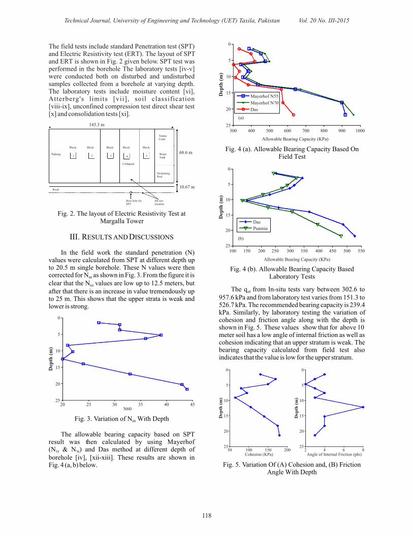
Fig. 4 (a). Allowable Bearing Capacity Based On Field Test
Fig. 4 (b). Allowable Bearing Capacity Based Laboratory Tests
The q from In-situ tests vary between 302.6 to all
957.6 kPa and from laboratory test varies from 151.3 to 526.7 kPa. The recommended bearing capacity is 239.4 kPa. Similarly, by laboratory testing the variation of cohesion and friction angle along with the depth is shown in Fig. 5. These values show that for above 10 meter soil has a low angle of internal friction as well as cohesion indicating that an upper stratum is weak. The bearing capacity calculated from field test also indicates that the value is low for the upper stratum.
Fig. 5. Variation Of (A) Cohesion and, (B) Friction Angle With Depth
118
The field tests include standard Penetration test (SPT) and Electric Resistivity test (ERT). The layout of SPT and ERT is shown in Fig. 2 given below. SPT test was performed in the borehole The laboratory tests [iv-v] were conducted both on disturbed and undisturbed samples collected from a borehole at varying depth. The laboratory tests include moisture content [vi], Atterberg's limits [vii], soil classification [viii-ix], unconfined compression test direct shear test [x] and consolidation tests [xi].
Fig. 2. The layout of Electric Resistivity Test at Margalla Tower
III. RESULTS AND DISCUSSIONS
In the field work the standard penetration (N) values were calculated from SPT at different depth up to 20.5 m single borehole. These N values were then corrected for N as shown in Fig. 3. From the figure it is 60
clear that the N values are low up to 12.5 meters, but 60
after that there is an increase in value tremendously up to 25 m. This shows that the upper strata is weak and lower is strong.
Fig. 3. Variation of N With Depth60
The allowable bearing capacity based on SPT result was then calculated by using Mayerhof (N & N ) and Das method at different depth of 55 70
borehole [iv], [xii-xiii]. These results are shown in Fig. 4 (a, b) below.
Technical Journal, University of Engineering and Technology (UET) Taxila, Pakistan Vol. 20 No. III-2015
143.3 m
Parking
Block Block Block Block Block
1 2 3 4 5
Collapsed
68.6 m
10.67 m
TennisCourt
WaterTank
SwimmingPool
Road
Bore hole forSPT
ER testlocation
Dep
th (
m)
0
5
10
15
20
2520 25 30 35 40 45
N60
Dep
th (
m)
0
5
10
15
20
25300
Allowable Bearing Capacity (KPa)
400 500 600 700 800 900 1000
Mayerhof N55
Mayerhof N70
Das
(a)
Dep
th (
m)
0
5
10
15
20
25
Allowable Bearing Capacity (KPa)
100 150 200 250 300 400 500 550350 450
Das
Punmia
(b)
Dep
th (
m)
0
5
10
15
20
2550 100 150 200
Cohesion (KPa)
Dep
th (
m)
0
5
10
15
20
252 4 6 8
Angle of Internal Friction (phi)

is less than 1 so equation 5 is to be used. It is the same equation which is used to find out the static
bearing capacity already manipulated. The Electric Resistivity tests (ERT) were
conducted along and parallel to Block 4 of Margalla Toweras shown in Fig. 2 above. The ERTresult parallel to the collapsed tower 4 is shown in Fig. 6 below.
It is clear from the Fig. that approximately 60 % stratum below the tower is soft material. Zones of high saturations were also marked. Trapped water (highly saturated zone) parallel to the underground water tank was found. This might be due to seepage from the underground water tank.
Fig. 6. Electric Resistivity Test (ERT) result ofMargalla Tower
The soil classification according to Unified Soil
Classification System (USCS) [viii] and American Association of Highway and Transportation Officials (AASTO) [ix] based on laboratory tests at different depth is given in TableI.
119
This allowable bearing capacity was also calculated based on Das and Punmia method [v xiv]. Using laboratory tests is plotted in Fig. 4b. From the Fig. 4 it is clearly shown that the allowable bearing capacity is low up to 10 m then it increases up to 25 m. The allowable bearing capacity is high from field tests as compare to laboratory tests.
After finding the static bearing capacity the dynamic bearing capacity of the soil is also figured out. We have following relations to find bearing capacity of soil. The use of equation depends on ratio of depth of footing (D ) and width of foundation (B) i.e. D /B. with f f
factor of safety of 3 the bearing capacity is calculated as under [xii].
(1)
(2)
Whereas F and F are,1 5
(3)
(4)
(5)
(6)
Whereas F and F are,1 2
(7)
(8)
Technical Journal, University of Engineering and Technology (UET) Taxila, Pakistan Vol. 20 No. III-2015
TABLE I
SOIL CLASSIFICATION BY UNIFIED SOIL CLASSIFICATION SYSTEM (USCS)
Depth(m)
1.5
3.5
8.5
10.5
14
20.5
0
0
0
2
1
2
Gravel(%)
11
9
7
8
9
2
Sand(%)
89
91
93
90
90
96
Silt & Clay (%)
5
6
12
6
8
15
Plasticity Index (%)
16
20
23
19
28
29
Liquid Limit (%)
CL-ML
CL - ML
CL
CL-ML
CL
CL
USCS
Silty Soil
Silty Soil
Clayey Soil
Silty Soils
Clayey Soil
Clayey Soil
Soil type
A-2-4
A-2-4
A-2-6
A-2-4
A-2-4
A-2-6
AASHTO
Silty or Clayey Soil
Silty or Clayey Soil
Silty or Clayey Soil
Silty or Clayey Soil
Silty or Clayey Soil
Silty or Clayey Soil
Soil type
From the AASTO and USCS soil classification system is it is clear that the soil is silty and clayey below
ground level. Subsurface soil profile is shown in Fig. 7.
0.0
6.3
12.7
19.0
25.3
HighlySaturatedZones
Dep
th (
m)
0 12 24 36 48 60 72 84 96 108 120 132 144100000
8538
729
62
5.3
Ohm-m
Inverted Resistivity Section Iteration = 4 RMS = 64.79% L2 = 466.02 Electrode Spacing = 12 m
156

The settlements were calculated at three clay samples obtained at respective depths and consolidation test was performed on these samples according to standard procedures using odometer apparatus. The laboratory test results were then used to plot graph between void ratio (e) and effective pressure to evaluate past maximum pressure ( ) as shown in
Fig. 8.
For under consolidated clay i.e., The equation 9 [v].
(9)
Similarly, for over consolidated clay i.e., the equation 10 is used.
(10)
The Table II shows the results of settlement of clay at three depths. The clay at 8.5 and 14 meters are under consolidated clays whereas the clay at 20.5 m is over-consolidated clay. These settlements were in the permissible limits (iv). It shows that the structure against settlement.
Schmertmann in 1970 proposed method based on SPT data to compute elastic settlement . To compute the settlement the soil below ground level was divided into five layers as shown in Fig. Each layer had a constant value of strain ( ) and soil modulus (E ) by using s
equation 11.
E = 300(N + 6) (11)S
The settlement was calculated by summing the influence of all layers.
120
Fig. 7. Subsurface profile
Fig.8. Void Ratio versus Effective Pressure (at 8.5 m)
Technical Journal, University of Engineering and Technology (UET) Taxila, Pakistan Vol. 20 No. III-2015
5 m
3 m
4 m
5 m
5 m
CL-ML N = 27, C=150 Kpa, °=260
CL N = 35, C=90 Kpa, °=260
CL-ML N = 21, C=90 Kpa, °=460
CL N = 30, C=140 Kpa, °=460
CL N = 42, C=175 Kpa, °=460
TABLE II
RESULTS OF SETTLEMENT ANALYSIS
Depth(m)
8.5
14
20.5
0.91
0.87
0.64
e
0.117
0.162
0.171
Cc
0.0117
0.0162
0.0171
Cs
180
190
485
óc
(kPa)
128
280
350
ó’
(kPa)
60
38
31
Äó’
(kPa)
0.95
0.59
1.2
OCR Settlement(m)
0.0038
0.061
0.00076
TABLE III
DATA FOR CALCULATION OF ELASTIC SETTLEMENT
1
2
3
4
5
Layer
0
3.5
8.5
10.5
14
Elevation top (m)
3.5
8.5
10.5
14
20.5
Elevation bottom (m)
3.5
5
2
3.5
6.5
0.503
0.503
0.503
0.503
0.503
Izp N60
27
35
21
30
42
Es (kPa)
9863
12300
8100
10800
14400
0.00019
0.00012
0.00025
0.00021
0.00016
= 0.00093
Voi
d R
atio
e
1
0.9
0.8
0.7
0.6
0.5
0.41 10 100 1000 10000180
Effective Pressure (Log Scale)

The variation of shear wave velocity and shear modulus is given in Fig. 10 (a, b). The Shear wave velocity calculated by three relations has average value of 337, 350 and 315 m/sec. These values fall in range of 175 to 350 m/sec. According to the building code of Pakistan the soil type is S which represents a Stiff Soil D
Profile [xv]. From these shear wave velocities the shear modulus was then calculated for known densities. The average values by JRA, Lee and Imai et al are 2348, 2629 and 2049 MPa, respectively as shown in Fig. 10 (a, b) below.
Fig. 10 (a). Variation of Shear Velocity with depth
Fig. 10 (b). Variation of Shear Modulus with depth
IV. CONCLUSION
The initial geotechnical investigation reveals that there were alternate layers of clay and silty clay with some gravel. It was confirmed by AASHTO and USCS SOIL soil classification system. The soil classification was also confirmed with electric resistivity (ER) results.
The soil up to 10 m is weak that is why raft
121
(11)
The following Table III shows the calculation of
the at different depth.
(12)
Similarly the settlement against 50, 75, 100 and 125 kPa was calculated and shown in Table IV.
Fig. 9. Variation of Settlement with increase in Net Bearing Stress
TABLE IV
NET BEARING CAPACITY AND SETTLEMENT
The graph between net bearing capacity and settlement is shown in Fig. 9. The foundation of the Margalla Tower was kept at 1.5 m below ground level. The bearing pressure on the foundation was 84.58 KPa. Whereas the net bearing pressure under the footing was
356.8 KPa (unit weight of soil is 19.81 KN/m ). The net bearing pressure (60 KPa) against 50 mm settlement was more than the applied net bearing pressure, i.e., 56.8 KPa under the foundation. Hence the Margalla tower was safe against settlement Shear velocity was calculated from observed N values based on the relationships of JRA 1980, Lee, 1990 and Imai et al., 1975 .
0.33V = 100N (13) [JRA]s
0.31V = 114N (14) [Lee 1990]s
0.31V = 90N (15) [Imai et. Al 1975]s
Technical Journal, University of Engineering and Technology (UET) Taxila, Pakistan Vol. 20 No. III-2015
25
14
50
39
75
70
100
106
125
143
Dep
th (
m)
0
5
10
15
20
25260 280 300 320 340 360 380 400
Vs (m/sec)
JRA 1980
Lee 1990
Imaiet al., 1975
Net Bearing Stress ( q ) kPa
0
25
50
75
100
125
150
175
Set
tlem
ent
( H
) m
m
0 25 50 75 100 125 15058
Dep
th (
m)
0
5
10
15
20
251000 1500 2000 2500 3000 3500
Gs (N/m2)
JRA 1980
Lee 1990
Imaiet al., 1975

Engineering, Sixth Edition”. Published by Thomson Limited, Canada. Chapter 6,
pp:147-154[v] B. M. Das, 2007. “Principles of Geotechnical
Engineering, Fifith Edition”. Published by Thomson Limited, Canada. Chapter 4, pp: 83 89 and Chapter 10, pp: 259-283
[vi] ASTM D-2216. “Standard Test Methods for Laboratoryoratory Determination of Water (Moisture) Content of Soil and Rock Mass”
[vii] ASTM D-4318. “Standard Test Methods for Liquid Limit, Plastic Limit and Plasticity Index of Soils
[viii] ASTM D-2487. “Standard Test Method for Classification of Soils for Engineering Purposes” Unified Soil Classification System (USCS)
[ix] ASTM D 3282. “Standard Practice for Classification of Soils and Soil-Aggregate Mixtures for Highway Construction Purposes” American Association of State Highway and Transportation Officials (AASHTO)
[x] ASTM D-3080. “Standard Test Method for Direct Shear Test of Soil Under Consolidated Drained Conditions”
[xi] ASTM D-2435. “Standard Test Methods One Dimensional Consolidation Properties of Soils Using Incremental Loading”
[xii] Joseph E. Bowles, 1996. “Foundation Analysis and Design” published by Mc Graw- Hill Companies, USA. Chapter three pp 167-179
[Xiii] R. D. Holtz and W. D. Kovacs, 1981. “An Introduction to Geotechnical Engineering”. Printed by Prentice Hall, New Jersey, USA. Chapter 8, pp: 284-296
[xiv] B. C. Punmia, 1994. “Soil Mechanics and Foundations” LAXMI Publications, New Delhi. Chapter Twenty Five , pp 737-738
[xv] Building Code of Pakistan (BCP), 2007. “Seismic Provision for Building Code of Pakistan” Ministry of Housing and Works Government of Pakistan Islamabad”
122
foundation was suggested.The average bearing capacity as calculated from
2 the field test is 575. 94 KN/m and from the laboratory 2tests is 386.10 KN/m .
The ERT result shows that there was seepage from the under -ground water tank which may be responsible for the decrease in in effective stress of the soil resulting in failure. .
The Schmertmann elastic strain method and consolidation test results showed settlement of 43 mm and 15.5 mm respectively. These values are within permissible limits for raft foundation. The Margalla Tower was thus safe with respect to settlement analysis.
The Shear wave velocity, thus calculated by three relations has an average value of 337, 350 and 315 m/Sec. These values fall in the range of 175 to 350 m/Sec indicating soil class S as per building code of D
Pakistan.In short the evaluation of geotechnical parameters
carried out in this research reveals that Margalla Tower was safe against bearing capacity and settlement. The soil stratum below Margalla Tower is firm and stiff non problematic soil. The failure was might be due to structural flaws. However, Authors would like to mention here that, the conclusions reached in this manuscript are based on bearing capacity and settlement analysis, further research on this topic like finite element modeling of building and earthquake loads during the shaking can refine the conclusions.
REFERENCES
[i] Capital Development Authority, 1992. “Geo-technical Report of the Site Construction of Flats in F-10/3, Islamabad”
[ii] Consolidated Engineering Services (CES) private Ltd, 1992. “Vetting Soil Investigation Report of Margalla Tower, F-10/3, Islamabad”
[iii] Geological Survey of Pakistan (GSP), 2006. “Tectonic Map of Pakistan”, Ministry of Petroleum and Natural Resources Islamabad
[iv] B. M. Das, 2007. “Principles of Foundation
Technical Journal, University of Engineering and Technology (UET) Taxila, Pakistan Vol. 20 No. III-2015