Embed Size (px)
Citation preview

GEOTECHNICAL INVESTIGATION For
APN 078-261-07 SWIM TANKS SITE
Ben Lomond, California
Prepared For SAN LORENZO VALLEY WATER DISTRICT
13060 Highway 9 Boulder Creek, California
Prepared By HARO, KASUNICH AND ASSOCIATES, INC.
Geotechnical & Coastal Engineers Project No. SC1 0706
September 2014

H ARO, KAsuNICH AND AssociATES, INc.
C ONSULTING G EOTECH NICAL & C OASTAL E NGINEERS
Project No. SC1 0706 16 September 2014
SAN LORENZO VALLEY WATER DISTRICT 13060 Highway 9 Boulder Creek, California 95006
Attention: Mr. Rick Rogers
Subject: Geotechnicallnvestigation
Reference: Replacement Water Storage Tank Swim Tanks Site 1 045 Country Club Drive APN 078-261-07 Ben Lomond, California
Dear Mr. Rogers:
In accordance with your authorization, we have performed a Geotechnical Investigation for the referenced replacement water tank project in Ben Lomond, California.
The accompanying report presents our conclusions and recommendations, as well as the results of the geotechnical investigation on which they are based.
If you have any questions concerning the data, conclusions and recommendations presented in this report, please call our office.
CAG/sr
Copies:
Respectfully Submitted ,
Christopher A George C.E. 50871
4 to Addressee+ 1 via email ([email protected])
1.1.6 EAST lAKE AVENUE • W ATS ONVIL L E , C ALIFORNIA 95076 • (831.) 722-41.7 5 • FAX (831.) 722-320 2

TABLE OF CONTENTS
Project No. SC10706 16 September 2014
GEOTECHNICAL INVESTIGATION ....................................................................... 1 Introduction ........................................................................................................... 1 Purpose and Scope .............................................................................................. 2 Site Location and Conditions .............................................................................. 3 Project Description ............................................................................................... 4 Field Exploration ................................................................................................... 4 Subsurface Conditions ......................................................................................... 6 Groundwater .......................................................................................................... 7 Laboratory Testing ................................................................................................ 7 Seismicity .............................................................................................................. 8 Slope Stability ..................................................................................................... 10
DISCUSSIONS, CONCLUSIONS AND RECOMMENDATIONS .......................... 12 Site Grading ......................................................................................................... 13 Cut and Fill Slopes .............................................................................................. 16 Spread Footing Foundations ............................................................................. 17 Seismic Design .................................................................................................. 19 Retaining Wall Lateral Pressures ...................................................................... 19 Concrete Slabs-on-Grade ................................................................................... 22 Utility Trenches ................................................................................................... 23 Site Drainage ....................................................................................................... 24 Erosion Control .................................................................................................. 24 Plan Review, Construction Observation and Testing ...................................... 25
LIMITATIONS AND UNIFORMITY OF CONDITIONS .......................................... 26
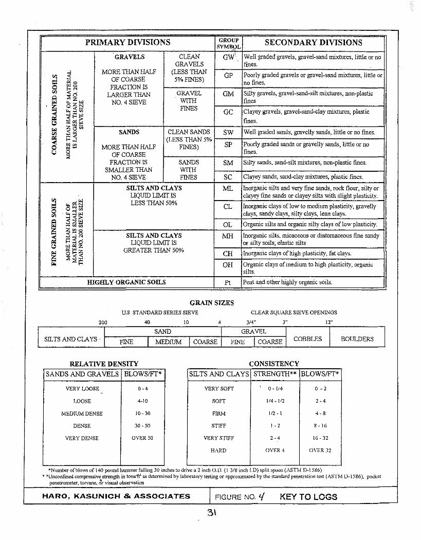
APPENDIX A ........................................................................................................ 27 Site Vicinity Map .................................................................................................. 28 Boring Site Plan .................................................................................................. 29 Cross Section A-A' .............................................................................................. 30 Key to Logs .......................................................................................................... 31 Logs of Test Borings .......................................................................................... 32 Grain Size Analysis Tests ................................................................................. 35 Direct Shear Test ................................................................................................ 37 Atterberg Limits Test Results ........................................................................... 38

GEOTECHNICAL INVESTIGATION
Introduction
Project No. SC10706 16 September 2014
This report presents the findings, conclusions and recommendations of our Geotechnical
Investigation for a proposed water tank replacement at the Swim Tanks Site in Ben
Lomond, California. As shown on the Site Vicinity Map (see Figure 1 in Appendix A), the
Swim Tanks Site is located on a moderately steep east facing slope located at 1045
Country Club Drive in Ben Lomond, California.
A Topographic Map for project site, dated June 2014, prepared by Paul Jensen, was
provided for our use. The map, which depicts the locations of existing water tanks and
slope contours, was used as a base for our Boring Site Plan (see Figure 2 in Appendix A).
Cross Section A-A' (see Figure 3 in Appendix A) was drawn based on contours shown on
the topographic map. Exploratory boring locations were not surveyed and should be
considered approximate only. Site descriptions, elevations, slope gradients and distances
referred to in this report are based on review of the map and site visits by the engineer.
Foundation and grading plans for the replacement tank or improvements had not been
developed at the time this report was prepared. Haro, Kasunich and Associates should be
provided an opportunity to review the project plans prior to finalizing to evaluate if the
criteria and recommendations presented were properly interpreted and implemented and
determine if this report is adequate and complete for proposed project.
1

Purpose and Scope
Project No. SC10706 16 September 2014
The purpose of our investigation was to evaluate the soil and bedrock conditions at the
referenced tank site and develop geotechnical design criteria and recommendations for the
proposed replacement water tank foundation and associated improvements. It is
presumed the most current California Building Code (CBC) edition design considerations,
specifically the seismic factors and coefficients from Chapter 16, Volume II, will be followed
during design and construction of the projects.
The specific scope of our services was as follows:
1. Site reconnaissance and review of available data in our files regarding the site
and vicinity.
2. A field exploration program consisting of Jogging and interval sampling of soils
encountered in three (3) exploratory borings drilled to depths of 15.5 to 16.5
feet. Standard Penetration Tests (SPT) were performed during sampling
operations. The soil samples obtained were sealed and returned to the
laboratory for testing.
3. Laboratory testing of select samples obtained. Moisture content and dry density
tests were performed to evaluate the consistency of the in situ soils. Gradation
analysis was performed to aid in soil classification. Atterberg Limits tests were
2

Project No. SC10706 16 September 2014
performed to evaluate the expansion potential of clay soil encountered in the
course of our exploration.
4. Engineering analysis and evaluation of the resulting data. We developed
geotechnical design parameters for foundations, concrete slabs-on-grade,
retaining walls, and recommendations for site grading, drainage and erosion
control.
5. Preparation of this report presenting the results of our investigation.
Site Locations and Conditions
The Swim Tanks Site (APN 078-261-07) is a small (6081 square foot) parcel located
southwest of the intersection of Country Club Drive, Woodland Drive, and Scenic Way in
Ben Lomond, California. The parcel is currently the site of two older 14 foot diameter
redwood water tanks spaced about 60 feet apart on the south portion of the parcel. Water
leakage from the tanks was flowing downslope to Woodland Drive at the time of our
investigation. Minor cuts have been made on the parcel to make the tank pads less steep
and to construct concrete pads for electrical panels and pumps.
The sloping site is bordered on the west and northwest by single family dwellings and an
undeveloped parcel to the north. The parcel has an average slope gradient of about 50
percent. East of the parcel, the slope continues to a steep 4' to 6' high cut slope along
3

Project No. SC 1 0706 16 September 2014
Woodland Drive. A short distance beyond the south property line, slopes descend to a
drainage channel which flows toward Woodland Drive.
The parcel is vegetated with several clusters of 1' to 2%' diameter redwood trees, scattered
smaller diameter oak trees and brush. Both existing tanks are in close proximity to
clustered redwood trees.
Project Description
A replacement water storage tank is proposed for the swim tanks site. The existing
redwood tanks will be demolished and removed. We understand the proposed new bolted
steel tank will be larger than the existing tanks and located between and to the north of the
current tank locations. The new tank will have a reinforced concrete ring foundation. A
retaining wall will be constructed to support excavations necessary to construct the new
tank pad. The project may also include the construction of a base rock surfaced or paved
driveway.
Grading for the project will consist of sub-excavation of soil in the tank pad and engineered
fill placement and compaction for the tank pad, driveway, and associated improvements.
Grading will also include excavation on the west side of the pad for the site retaining wall.
Field Exploration
Subsurface conditions were investigated on 1 July 2014 by drilling three (3) exploratory
4

Project No. SC10706 16 September 2014
borings to depths of 15.5 and 16.5 feet. The boring locations were not surveyed and should
be considered approximate only. The borings were drilled with 4-inch diameter, continuous
flight auger equipment mounted on a motor driven limited access drill rig. The approximate
locations of the borings are shown on the Boring Site Plan (see Figure No.3 in Appendix
A).
Representative soil samples were obtained from the exploratory borings at selected
depths, or at major strata changes. These samples were recovered using a 3.0 inch
outside diameter (O.D.) Modified California Sampler (L}, or by a 2.0 inch 0. D. Standard
Terzaghi Sampler (T). The soils encountered in the borings were continuously logged in
the field and visually described in accordance with the Unified Soil Classification System
(ASTM 02487). The Logs of Test Borings are included in the Appendix of this report. The
Logs depict subsurface conditions at the approximate locations shown on the Boring Site
Plans. Subsurface conditions at other locations may differ from those encountered at the
explored locations. Stratification lines shown on the logs represent the approximate
boundaries between soil types; actual transitions may be gradual.
The penetration blow counts noted on the boring logs were obtained by driving a sampler
into the soil with a 140-pound hammer dropping through a 30-inch fall. The sampler was
driven up to 18 inches into the soil and the number of blows counted for each 6-inch
penetration interval (Standard Penetration Test). The numbers indicated on the logs are
the total number of blows that were recorded for the second and third 6-inch intervals, or
5

Project No. SC10706 16 September 2014
the blows that were required to drive the penetration depth shown if high resistance was
encountered.
Subsurface Conditions
Based on the results of our subsurface exploration, the proposed replacement tank site is
underlain by loose sandy silt and silty lean clay topsoil from the surface to depths of 2 to 4
feet. Below the topsoil, stiff to very stiff lean clay, clayey silt and siltstone was found to the
depths explored in Boring Nos. 1 and 2 (16.5 feet) and to a depth of 13 feet in Boring No.
3. Hard siltstone was encountered from 13 feet to the depth explored (15.5 feet). Boring 3
drilling was terminated at 15.5 feet due to refusal on very hard siltstone rock.
A review of "The Geologic Map of Santa Cruz County, California" (Brabb, 1989) indicates
that the site is mapped as Tm: Monterey Formation (middle Miocene) -Medium to thick-
bedded and laminated olive-gray to light-gray semisiliceous organic mudstone and sandy
siltstone. Includes a few thick dolomite interbeds. Thickness about 2,675 feet on north limb
of Scotts Valley syncline (Clark, 1981, p.21).
The weathered siltstone and clayey siltstone and hard siltstone encountered in our borings
is typical of the Monterey Formation mudstone and siltstone.
6

Groundwater
Project No. SC10706 16 September 2014
Groundwater was not encountered in our borings. However, groundwater levels will
fluctuate with time, being dependent upon seasonal precipitation, irrigation, land use, and
climate conditions as well as other factors. Therefore, water observations at the time of the
field investigation may vary from those encountered during the construction phase and/or
post-construction of the project. The evaluation of such factors is beyond the scope of our
study.
Laboratory Testing
The laboratory testing program was directed toward determining pertinent engineering and
index soil properties.
The natural moisture contents and dry densities were determined on selected samples and
are recorded on the boring logs at the appropriate depths. Since the engineering behavior
of soil is affected by changes in moisture content, the natural moisture content will aid in
evaluation of soil compressibility, strength, and potential expansion characteristics. Soil dry
density and moisture content are index properties necessary for calculation of earth
pressures on engineering structures. The soil dry density is also related to soil strength
and permeability.
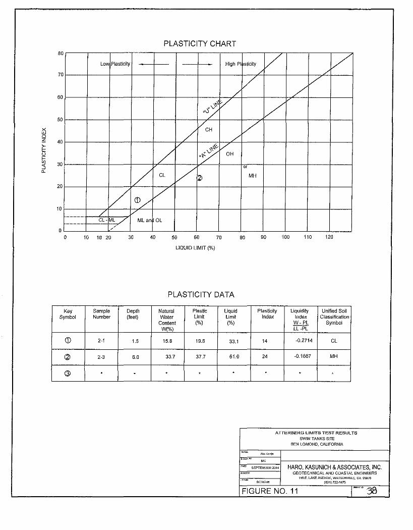
Atterberg Limits tests were performed on selected soil samples to evaluate the range of
moisture contents over which the soil exhibits plasticity, and to classify the soil according to
7

Project No. SC10706 16 September 2014
the Unified Soil Classification System. The plasticity characteristics of a soil give an
indication of the soil's compressibility and expansion potential. Grain size analysis tests
were performed to aid in soil classification. The results of Atterberg Limits tests (PI=14 and
Pl=24, respectively) and Grain size analysis tests indicate the soils at depths of 1.5 feet
and 6.0 feet in Boring 2 at the Swim Tanks Site are classified as lean clay(CL) and elastic
silt (MH). Based on field observation and additional laboratory testing, soil at other
locations and depths in the test borings was classified as sandy silt (ML) and silty lean clay
(CL).
The strength parameters of the underlying earth materials were determined from a Direct
Shear Test performed in the laboratory and from Standard Penetration Test (SPT) blow
count measurements obtained in the field during sampling of in-situ soil. The Direct Shear
Test sample was saturated for 24 hours prior to testing. The results of the field and
laboratory testing appear on the "Logs of Test Boring" opposite the sample tested.
Seismicity
The following is a general discussion of seismic considerations affecting the project area.
Detailed studies of seismicity, faulting and other geologic hazards are beyond the scope of
this study.
The Swim Tanks site is located at Latitude 37.080973° North and Longitude 122.09243r
West (Google Earth). The active San Andreas Fault Zone and the potentially active
8

Project No. SC10706 16 September 2014
Zayante Fault Zone and Ben Lomond Fault, are located about 6.8 miles, 2.5 miles, and 0.3
miles from the project site, respectively.
The San Andreas Fault zone is a major fault zone of active displacement which extends
from the Gulf of California to the vicinity of Point Arena, where the fault leaves the
California coastline. Between these points, the fault is about 700 miles long. The fault
zone is a break or series of breaks along the earth's crust, where shearing movement has
taken place. This fault movement is primarily horizontal.
The largest historic earthquake in Northern California occurred on 18 April 1906 (M8.3+).
The 17 October 1989 Loma Prieta earthquake (M6.9) is also considered to have been
associated with the San Andreas Fault system. This event was the second largest
earthquake in Northern California this century. Strong ground shaking was experienced
throughout Santa Cruz County during both of these seismic events.
Although research on earthquake prediction has greatly increased in recent years,
seismologists have not yet reached the point where they can predict when and where
another large earthquake will occur. Nevertheless, on the basis of current technology, it is
reasonable to assume that the proposed development will be subject to at least one
moderate to severe earthquake during the fifty year period following construction.
9

Project No. SC10706 16 September 2014
Potential seismic hazards include surface ground rupture, liquefaction effects, damage
from strong seismic shaking, and landsliding.
Since no known faults cross the project site, the potential for surface ground rupture is low.
Because of the stiff to very stiff consistency of the weathered siltstone and clayey siltstone
and hard siltstone underlying the Swim Tanks site, the potential for seismic induced
liquefaction at the site is low. During a major earthquake there is potential for severe
ground shaking at this site. In our opinion, structures designed in accordance with the
most current California Building Code (2013 CBC) should perform adequately during strong
seismic shaking.
Slope Stability
During our field investigation and site reconnaissance, we did not observe any visual
indications of instability of the moderately steep natural slopes at the tank site. The tanks
have been on the site for many years and do not appear to have experienced damage as a
result of slope instability. A review of the Preliminary Map of Landslide Deposits in Santa
Cruz County (Cooper-Clark, 197 4) indicates the site is an area mapped as a large probable
landslide deposit of about 450 acres (±) in size. The mapped landslide deposit
encompasses hundreds of occupied parcels. We have reviewed a geologic report in our
files for another property within the suspected landslide deposit. The geologist noted that
the deposit was not mapped on a regional geologic map. In an examination of stereo aerial
10

Project No. SC1 0706 16 September 2014
photographs, he concluded there was no evidence in the aerial photographs to support the
existence of the landslide, notably the absence of a landslide headscarp.
As we noted above, we did not observe any indications of instability on the site nor did
conditions encountered in our borings indicate potential instability. However, a quantitative
analysis of the static and seismic stability of the site and large landslide is beyond the
scope of work detailed in our proposal agreement.
11

Project No. SC 1 0706 16 September 2014
DISCUSSIONS, CONCLUSIONS AND RECOMMENDATIONS
Based on the results of our investigation, the proposed construction of a replacement water
tank on the Swim Tanks Site is acceptable from a geotechnical standpoint, provided the
following geotechnical criteria and recommendations are incorporated into the design and
construction of the project.
Geotechnical considerations at the Swim Tanks Site include the presence of loose near
surface soil, providing firm uniform bearing support for the tank foundations, slope stability,
the potential for strong seismic shaking, and providing adequate site drainage.
Based on our subsurface exploration and testing, the near surface soil at the tank site
consists of loose sandy silt topsoil, stiff to very stiff weathered siltstone and clayey siltstone
of variable strength. Test results indicate the soil has 55 to 75 percent fines (clay and silt).
The fine grained soils are moderately expansive, difficult to compact and unsuitable for use
as structural fill. To provide firm uniform support for the replacement water tank, we
recommend topsoil and the top 4 feet of soil at the site be sub-excavated, removed off site
and replaced with select non-expansive engineered fill.
Concentrated surface runoff from the project site should not be allowed to flow onto the
slopes at the site. We recommend roof and surface runoff be directed to collection
facilities and conveyed to the paved road downslope of the Swim Tanks site.
12

Project No. SC1 0706 16 September 2014
The project site is located within a seismically active area. The proposed replacement
water tank should be designed in accordance with the most current CBC (20 13) seismic
design standards.
The following recommendations should be used as guidelines for preparing project plans
and specifications.
Site Grading
1. The geotechnical engineer should be notified at least four (4) working days prior to
any grading or foundation excavating so the work in the field can be coordinated with
the grading contractor and arrangements for testing and observation can be made. The
recommendations of this report are based on the assumption that the geotechnical
engineer or representative will perform the required testing and observation during grading
and construction. It is the owner's responsibility to make the necessary arrangements for
these required services.
2. Where referenced in this report, Percent Relative Compaction and Optimum Moisture
Content shall be based on ASTM Test Designation D1557.
3. Areas to be graded should be cleared of all obstructions, including existing
foundations and structures, old fill, trees not designated to remain and other unsuitable
material. Disturbed soil resulting from demolition and clearing operations should be
13

Project No. SC10706 16 September 2014
removed off site. Existing depressions or voids created during site clearing should be
backfilled with engineered fill.
4. The remaining cleared areas should then be stripped of organic-laden topsoil.
Stripping depth is anticipated to be from 4 to 6 inches. Actual depth of stripping should be
determined in the field by the geotechnical engineer. Strip pings should be wasted off-site
or stockpiled for use in landscaped areas if desired.
5. Following clearing and stripping, the tank pad should be sub-excavated and replaced
with select non-expansive engineered fill. At a minimum, the sub-excavation should include
the top 4 feet of soil on the tank site. The depth of sub-excavation is an estimate only. The
geotechnical engineer should be on site during grading to evaluate the conditions and
depth of loose soil to determine the actual depth of sub-excavation. The tank pad should
extend a minimum of 5 feet beyond the foundation perimeter. Excavated soil should be
removed offsite.
6. The bottom of the sub-excavation and all areas to receive fill should be scarified,
moisture conditioned (or allowed to dry as necessary) to produce a moisture content within
2 percent of the laboratory optimum value, and uniformly compacted to a minimum of 90
percent relative compaction based on ASTM Test 01557. The recommended depth of
scarification will depend upon the density of the underlying bedrock and should be
determined in the field by the engineer during grading.
14

Project No. SC10706 16 September 2014
7. If grading is performed during or shortly after the rainy season or if saturated soil from
leaking water tanks is not allowed to dry back, the grading contractor may encounter
compaction difficulty, such as pumping or bringing free water to the surface in the near
surface soils. If compaction cannot be achieved after reducing the soil moisture content, it
may be necessary to overexcavate the subgrade soil and replace it with angular crushed
rock to stabilize the subgrade. The need for ground stabilization measures to complete
grading effectively should be determined in the field at the time of grading, based on
exposed soil conditions.
8. Engineered fill should be placed in thin lifts not exceeding 8 inches in loose thickness,
moisture conditioned, and compacted to a minimum of 95 percent relative compaction.
The upper 6 inches of slab or pavement subgrade and aggregate base below pavements
should be compacted to a minimum of 95 percent relative compaction.
9. The on-site silt and clay soil is acceptable for use as engineered fill. Soil imported
for use as engineered fill should consist of a predominantly granular soil conforming to the
quality and gradation requirements as follows: Imported soil should be relatively free of
organic material and contain no rocks or clods greater than 4 inches in diameter, with no
more than 15 percent larger than 2% inches. The material should be predominately
granular with a plasticity index (PI) <12, a liquid limit less than 35 and not more than 35
percent passing the No. 200 sieve, Engineered fill should also have sufficient binder so
that footing and utility trenches will not collapse.
15

Project No. SC10706 16 September 2014
10. We estimate shrinkage factors of 15 to 25 percent for the on-site materials when
compacted as engineered fill.
Cut and Fill Slopes
11. Temporary excavations should be properly shored and braced during construction
to prevent sloughing and caving at sidewalls. The contractor should be aware of all CAL
OSHA and local safety requirements and codes dealing with excavations and trenches.
12. Permanent cut slopes should be inclined no steeper than 2:1 (horizontal to vertical).
The top of all cut slopes should be rounded off to reduce soil sloughing. If seepage is
observed, the geotechnical engineer should provide additional recommendations. Cut
slopes with these recommended gradients may require periodic maintenance to remove
minor soil sloughing.
13. Compacted fill slopes should be constructed at a slope inclination no steeper than
2:1 (horizontal to vertical). Fill slopes with this recommended gradient may require periodic
maintenance to remove minor soil sloughing. All fills must be adequately benched into
competent material. Keyways for stability are required at the toe of fill embankments. Toe
keys should be at least 6 feet wide and should extend at least 1 Y2 feet into competent soil
or bedrock. The bottom of the toe key should be sloped downward at about 2 percent
toward the back of the key. Where seepage is observed, keyways should have subdrains.
16

Project No. SC 1 0706 16 September 2014
The location of subdrains and outlets should be determined by the geotechnical engineer
in the field during grading.
14. Following grading, exposed soil should be planted as soon as possible with
erosion-resistant vegetation.
15. After the earthwork operations have been completed and the geotechnical
engineer has finished his observation of the work, no further earthwork operations shall be
performed without the direct observation and approval of the geotechnical engineer.
Spread Footing Foundations
16. The actual dimensions of the ring-type footings should be determined by the design
professional. However, as a minimum, footings should be 15 inches in width, penetrate
loose soil and be embedded a minimum of 18 inches into engineered fill. The footings
should be reinforced as required by the structural designer based on the actual loads
transmitted to the foundations.
17. The bottom of all foundation elements should have a minimum setback of 5 feet
horizontally from adjacent slopes.
18. The foundation trenches should be kept moist and be thoroughly cleaned of all
slough or loose materials prior to pouring concrete. In addition, all footings located adjacent
17

Project No. SC10706 16 September 2014
to other footings should have their bearing surfaces founded below an imaginary 1%:1
plane projected upward from the bottom edge of the adjacent footings or utility trenches.
19. Provided the water tank pad is redensified as recommended in the grading section
of this report and the water tank and foundations are embedded in and underlain by
redensified engineered, foundations may be designed for an allowable soil bearing
pressure of 2500 psf for dead plus live loads. These values may be increased by one-third
to include short-term seismic and wind loads.
20. Provided our recommendations are followed during design and construction of the
project, post-construction total and differential settlement of foundations are expected to be
less than 1 inch and % inch, respectively.
21. Lateral load resistance for the tank footings may be developed in friction between
the foundation bottom and the supporting subgrade. A friction coefficient of 0.35 is
considered applicable. An allowable passive pressure of 170 pcf may be used below a .
depth of 12 inches.
22. All footings should be reinforced in accordance with applicable CBC and/or ACI
standards. We recommend the footings contain a minimum steel reinforcement of four (4)
No.4 bars; i.e., two near the top and two near the bottom of the footing.
18

Project No. SC10706 16 September 2014
23. The footing excavations should be thoroughly cleaned and observed by the
geotechnical engineer prior to placing forms and steel, to verify subsurface soil conditions
are consistent with the anticipated soil conditions and the footings are in accordance with
our recommendations.
Seismic Design
24. The 2010 ASCE 7 provides site class definitions for seismic design of structures.
Based on these definitions and review of the site soil properties presented on our soil
boring logs, the soil at the Swim Tanks site is classified Site Class D in accordance with
Table 20.3-1 in ASCE 7. The project site is located at Latitude 37.080973° North and
Longitude 122.09243r West.
25. The following maximum considered earthquake and five percent damped design
spectral response accelerations adjusted for site class effects should be used for seismic
design based on Sections 1613.3.1 to 1613.3.4 of the 2013 CBC.
A. SMs = 1.500 (0.2- second period)
B. SM1 = 0.915 (1.0 -second period)
C Sos = 1.000 (0.2 -second period)
D. So1 = 0.610 (1.0- second period)
Retaining Wall Lateral Pressures
26. Where retaining walls are designed for support of the cut or fill slopes, the walls
19

Project No. SC10706 16 September 2014
should be designed to resist both lateral earth pressures and any additional surcharge
loads. Spread footings may be used for walls provided there is a minimum of 5 feet
horizontally from the foundation to adjacent slopes. Where retaining walls will be
constructed on slopes steeper than 5:1, the wall should be founded on reinforced concrete
piers. For design of fully drained retaining walls up to 10 feet high, the following design
criteria may be used:
A. Active earth pressure for walls allowed to yield (up to% percent of wall height)
is that exerted by an equivalent fluid weight of 45 pcf for a level backslope
gradient and 60 pcf for a 2:1 (horizontal to vertical} backs lope gradient. This
assumes a fully drained condition.
B. Where walls are restrained from moving at the top, design for a uniform
rectangular distribution equivalent to 30H psf per foot of wall height for a level
backslope, and 39H psf per foot of wall height for a 2:1 backslope (where His
the height of the wall).
C. In addition, the walls should be designed for any adjacent surcharge loads
which will exert a force on the wall.
D. Use a coefficient of friction = 0.30 between the base of foundations and
native soil. Where retaining wall footings are poured neat against native soil,
20

Project No. SC10706 16 September 2014
a passive resistance of 170 pcf (EFW) may be used. The top 12 inches of
soil should be neglected when computing passive resistance.
E. Where retaining walls are founded on reinforced concrete piers, the piers may
be designed for an allowable skin friction of 350 psf plus a 1/3 increase for
short term wind and seismic loads. The top 1 foot of soil in the pier hole
should be neglected for pier design.
F. Piers should have a minimum diameter of 18 inches and reinforced as
required by the structural designer. Actual reinforcement requirements should
be determined by the structural designer.
G. For lateral resistance, the piers may be designed for a passive pressure
equivalent to a fluid weight of 170 pcf and may be assumed to act against 1%
pier diameters. The top 1 foot of soil should be neglected for pier design.
H. The geotechnical engineer should observe the pier excavations during pier
drilling to confirm anticipated soil conditions. Prior to placing steel
reinforcement and pouring concrete, pier holes should be thoroughly cleaned
of loose soil.
21

Project No. SC1 0706 16 September 2014
I. For seismic design of retaining walls, a dynamic surcharge load equal to 12H2
per foot of wall, acting at 0.6H from the top of the wall, where H is the height
of the wall, should be added to the above active lateral earth pressures.
J. Fully drained walls should be backfilled with drainage materials consisting of
Class 1, Type A permeable material complying with Section 68-1.025 of
Caltrans Standard Specifications, latest edition.
K. The drainage material should be at least 12 inches thick. The drains should
extend from the base of the walls to within 12 inches of the top of the backfill.
A perforated, rigid pipe should be placed (holes down) about 4 inches above
the bottom of the wall and be tied to a suitable drain outlet. Wall backdrains
should be capped at the surface with clayey material to prevent infiltration of
surface runoff into the backdrains. A layer of filter fabric (Mirafi 140N or
equivalent) should separate the subdrain material from the overlying soil cap.
Concrete Slabs-on-Grade
27. Concrete slabs should be constructed on properly moisture conditioned and
compacted engineered fill. Engineered fill should be prepared and compacted as
recommended in the section entitled "Site Grading".
22

Project No. SC10706 16 September 2014
28. The project design professional should determine the appropriate slab reinforcing
and thickness, in accordance with the anticipated use and loading of the slab. However,
we recommend a minimum reinforcement of #4 bars spaced 16 inches on-center in both
directions. The steel reinforcement should be held firmly in the vertical center of the slab
during placement and finishing of the concrete with pre-cast concrete dobies. In addition,
we recommend that consideration be given to a minimum slab thickness of 5 inches and
steel reinforcement necessary to address temperature and shrinkage considerations.
Utility Trenches
29. Trenches must be properly shored and braced during construction or laid back at an
appropriate angle to prevent sloughing and caving at sidewalls. The project plans and
specifications should direct the attention of the contractor to all CAL OSHA and local safety
requirements and codes dealing with excavations and trenches.
30. Utility trenches should be placed so that they do not extend below an imaginary line
sloping down and away at a 1%:1 (horizontal to vertical) slope from the bottom outside
edge of all footings. The structural design professional should coordinate this requirement
with the utility layout plans for the project.
31. Trenches should be backfilled with granular-type material and uniformly compacted
by mechanical means to the relative compaction as required by county specifications, but
not less than 95 percent under paved areas and 90 percent elsewhere. The relative
23

Project No. SC10706 16 September 2014
compaction will be based on the maximum dry density obtained from a laboratory
compaction curve run in accordance with ASTM Procedure 01557.
32. Trenches should be capped with a minimum of 12 inches of compacted relatively
impermeable soil.
Site Drainage
33. Surface drainage should include provisions for positive gradients so that surface
runoff is not permitted to pond adjacent to tank foundations, pavement or other
improvements. Roof and surface runoff should be directed away from foundations to
collection facilities and conveyed via buried plastic pipes to the toe of slopes at the tank
sites. The pipe outlet facilities should be designed so that instability and/or erosion does
not occur at the outlet. Concentrated surface runoff should not be allowed to flow on the
slopes below the tank site.
Erosion Control
34. The soil at the project site has potential for erosion where unvegetated. We
recommend the following provisions be incorporated into the project plans:
A. All grading and soil disturbance shall be kept to a minimum.
B. No eroded soil shall be allowed to leave the site.
C. All bare soil should be seeded and mulched immediately after grading with
barley, rye, grass and crimson clover and covered with straw.
24

Project No. SC 1 0706 16 September 2014
D. Prior to the rainy season bare soil on cut or fill slopes should be well
vegetated or protected from erosion by installation of ground cover or
properly installed erosion control blankets.
35. The migration of water or spread of extensive root systems below foundations,
slabs, or pavements may cause undesirable differential movements and subsequent
damage to these structures. Landscaping should be planned accordingly.
Plan Review, Construction Observation and Testing
36. Haro, Kasunich and Associates must be provided an opportunity to review project
plans prior to construction to evaluate if our recommendations have been properly
interpreted and implemented. We should also provide foundation excavation observations
and earthwork observations and testing during construction. This allows us to confirm
anticipated soil conditions and evaluate conformance with our recommendations and
project plans. If we do not review the plans or provide observation and testing services
during the earthwork phase of the project, we assume no responsibility for misinterpretation
of our recommendations.
25

Project No. SC10706 16 September 2014
LIMITATIONS AND UNIFORMITY OF CONDITIONS
1. The recommendations of this report are based upon the assumption that the soil
conditions do not deviate from those disclosed in the borings. If any variations or
undesirable conditions are encountered during construction, or if the proposed
construction will differ from that planned at the time, our firm should be notified so
that supplemental recommendations can be given.
2. This report is issued with the understanding that it is the responsibility of the owner,
or his representative, to ensure that the information and recommendations contained
herein are called to the attention of the Architects and Engineers for the project and
incorporated into the plans, and that the necessary steps are taken to ensure that the
Contractors and Subcontractors carry out such recommendations in the field. The
conclusions and recommendations contained herein are professional opinions
derived in accordance with current standards of professional practice. No other
warranty expressed or implied is made.
3. The findings of this report are valid as of the present date. However, changes in the
conditions of a property can occur with the passage of time, whether they be due to
natural processes or to the works of man, on this or adjacent properties. In addition,
changes in applicable or appropriate standards occur whether they result from
legislation or the broadening of knowledge. Accordingly, the findings of this report
may be invalidated, wholly or partially, by changes outside our control. Therefore,
this report should not be relied upon after a period of three years without being
reviewed by a geotechnical engineer.
26

APPENDIX A
Site Vicinity Map
Boring Site Plan
Cross Section A-A'
Key to Logs
Logs of Test Borings
Grain Size Analysis Tests
Direct Shear Test
Atterberg Limits Tests
27
Project No. SC10706 16 September 2014

SLVWD SWIM TANKS SITE
FROM: USGS Felton Topographic Quadrangle. 1955, pholorevised 1980. 40 ft. contour interval
/}
-.... ... ... ..
S ITE V ICINITY MAP San Lorenzo Valley Water District- Swim Tanks Site
APN 078-261-07 1045 Country Club Drive
SCA.l..E.. t·24,000 ( I" z 2,000")
0"-'WNBV JQ
DAtE. July 2014 ~SEO
JOB NO SC10706
Ben Lomond, California
HARO, KASUNICH & ASSOCIATES, INC. GEOTECHNICAL AND COASTAL ENGINEERS
116 E. LAKE AVENUE. WATSONVILLE. CA 95076 (83t) 722-4115
FIGURE NO. 1

~
1 ;e I I
Lot 16 Block 17
\ \ . ) ~~· ,.,~·w · 1(51 I) . \ (89·
9 ·.
\ 1 : I ~ \ . tT
I ! • I I . . I I• I
\ 0 1,~
~ I -...!
~ I \ \ \ \ \ 1 !B"a I : .1 1 \
l : • QAJ<W ~ 1
1 •,
I . ·. ) .. ...... I • \ • ' I . ~ ,. I . .
\
-l ':'o ll.)'l I \ ·. I ()'> ' • • <.1' \ '. : ·, '1 ; • 1 \ ; 1 I \ I ; !
~1 3~ Otl ,
• I I ·. I \ I
; \ ; I • \ ·• ~ i • \ I .' • 1 I , 1
, . \ ' I · .• I I . I I
'$~.I I ~ . I
$ . OA.JS • ""' ' 9 . • . 0 ·0/IK I 1 • \
• f I ' 10" ' \ ' ' . I ' ~OAK • • I \
I · · 1 • ' \ • • . lr • : :' I I ) • • • ~1 ?" LOI.'I . 7 I • . I ~ , ...... ,'l~··. . I ~C·V . . . . ' '\ '"" . . . .
I . I . • • I I I ·~ .!' REDWOOD I ' ' • • , I • I I • •
I . : . . I I I \ , · I I ' I i loo· I 1
: ' ~. • · o b . · 2. . I . . f . AI< I ' R::O'II 0 ,) · I . . : I i . I
I : ' I , I . I : I ; I . I I . ' & . I ' ; I I
~ LOT · g / I I
IJ')
/;; I
I
I' I 2s· .. ,
1RC:D'IIOOD' " : r; ......... I 1'2·;
I RCDWOOO I
I ·a· REDWOCJ
\ \
0'?"' 0/1.< \ ~
'· ~ I
' \ ~ · ' \ II · \ , <f;:CV/~00'0
' ...... ......
·. 2s"l···, ~toWO?C·...._ ••
\ ~ ~
\ \ \ \ \
\ \
\ \
\ \
\ I I I I
(l
' ' •V, eo
~
~ I \ l \ I :
I o
I .' .. . ! .... t I ... . I : . . : .'
I . .; ,' I . : .
! ( :' .: :: ... , . .. . . i ... : , :;
· ·o.: . . . ·~ · ......... .. : tS ·I • .
: : ; I . I ~ ! .': I I I I • I I .
• I I : . d' ;l:-
0 /;; i
') ~..s..s· '· . { • RDWOOD ·· .. ,
\, ~/l
P.P. c;:). d'
I I
/ I
I I
I I
I
32" • ·-., REDWCOD \... ~
---.- . 2'-'"
'..._,.' REDWOOD
KEY:
• l() v ...... I
,
B-~ =SOIL BORING LOCATION
A A' L_j = CROSS SECTION LINE
BORING SITE PLAN San Lorenzo Valley Water District· Swim Tanks Site
APN 078-261-07 1045 Country Club Drive
IICAll: , •• 12'
DAAWHBV: ~
OATI: July 2014
RE\'ISEE> Sepl 2014
JOONO. SC10706
Ben Lomond, California
site plan from Paul Jensen, Surveyor. dated June 2014
HARO, KASUNICH & ASSOCIATES, INC. GEOTECHNICAL AND COASTAL ENGINEERS
118 E. LAKE AVENUE, WATSONVILLE. CA teO'Ie (531 )122.4175
-
FIGURE NO.2 ....... Qq

760
750
740-
730
720
~ w f!:.. z 0
~ w _,
A
32" REDW\)O)D~ (PROJ. 2.0 N ~ I ----- 28" REDWOOD
~ (PROJ. 2.5' N)
rap~'- ~ /Vt, ~ITO!f. - 2 ~ 2tt£'-E2o o~ --!! 8-"lJ\i~-~>ZJ~~ ,y''8#{'~%, ~ ""'' 'Oo B-3 0
"'~'l§l?f2{f~-,.o vR/[.}SA.~ §g_ .. \li'il1..<J ~'loA/ S7ft=:t=: ~ Yf2y-Sit_
I) (Sit. ~'r-c :l...<Jy
I.
-?- - -?- - -?- ---t---.
REDWOOD WATER TANK (PROJ. 7' N)
,r- I
I I CONC. PAD I I
A' TAN SANDY SILTSTONE, VERY HARD (MONTEREY FORMATION)
WOODLAND DR.
W L----------------------------------------------------------------------------,----------~C~RrO~S~S~S~E~C~T~I~O~NTAA<-A~.----------~ CROSS SECTION BASED ON P. JENSEN TOPO SURVEY JUNE 2014
~0 GRAPHIC SCALE 1" = 1 0'
HORIZONTAL =VERTICAL
NOTE: FOR ILLUSTRATIVE PORPOSES ONLY NOT TO BE USED FOR CONSTRUCTION
San Lorenzo Valley Water District~ Swim Tanks Site APN 078-261-07 1045 Country Club Drive
Ben Lomond, California S<:A!.f: 1"=1Q'
DNAWNSY: JQ
oAr~: september 2014 Rev,,~u.
JOS NO. SC1 0706
HARO, KASUNICH & ASSOCIATES, INC. GEOTECHNICAL AND COASTAL ENGiNEERS
116 E. LAKE AVENUE, WATSONViLLE, CA 95076 (831) 72:2.4175
FIGURE N0.3 1"'"00
30
PRIMARY DIVISIONS GROUP SECONDARY DIVISIONS SYMBpL
GRAVELS CLEAN GW '· Well graded gravels, gravel-sand mixtures, little or no
GRAVELS fmes.
g MORE THAN HALF (LESS THAN GP Poorly graded gravels or gravel-sand mixtures, little or d "'o OF COARSE 5%FINES) no fines.
0 "'o FRACTION IS f-N
"' -< . LARGER THAN GRAVEL GM Silty gravels, gravel-sand-silt mixtares, non-plastic ~ :::;l1
~ "- "" NO. 4S!EVE WTIH fines O:i!:::J FINES
GC Clayey gravels, gravel-sand-clay miA1ures, plastic ~:::"' -~~ fmes. t.!l """tt.:~~
"' :i!C"' SANDS CLEAN SANDS sw Well graded sands, gravelly sands, little or no fines. "' ?:~ ~ (LESS THAN 5% Poorly graded sands or gravelly sands, little or no 0 gjf!l MORE THAN HALF FINES) SP
[,) 0 OF COARSE fmes. ;:; FRACTION IS SANDS SM Silty sands, sand-silt mixtares, non-plastic fmes.
SMALLER THAN WITH NO. 4S!EVE FINES sc Clayey sands, sand-clay mixtures, plastic fmcs.
SILTS AND CLAYS ML Inorganic silts and very fine sands, rock flour, silty or
~ LIQUID LIMIT IS clayey fme sands or clayey silts with slight plasticity.
"'"' LESS THAN 50% Inorganic clays of low to medium plasticity, gravelly - ~ 't.l :::l CL 0 or "' . "' ~ clays, sandy clays, silty clays, lean clays . ~ :L.!!l OL Organic silts and organic silty clays of low plasticity. "' ~"'"' as :i!"'O -o SILTS AND CLAYS MH Inorganic silts, micaceous or diatomaceous fme sandy ~ ~~~
;;;0 LIQUID LIMIT IS or silty soils, elastic silts t.!l gj..,Z GREATER THAN 50%
~ o~:i! CH Inorganic clays of high plasticity, fat clays. :::;:::;:::
r-. f. OH Organic clays of medium to high plasticity, organic silts.
HIGHLY ORGANIC SOILS Pt Peal an_d other highly organic soils.
GRAIN SIZES
U.S ST A<'IDARD SERIES SIEVE CLEAR SQUARE SIEVE OPENINGS
200 40 10 4 3/4" 3" 12"
SAND GRAVEL S!LTSANDCLAYS · FINE I MEDIUM I COARSE FINE I COARSE COBBLES BOULDERS
RELATIVE DENSITY CONSISTENCY
SANDS AND GRAVELS BLOWS/FT* SILTS AND CLAYS STRENGTH** BLOW SIFT*
VERY LOOSE 0-4 VERY SOFT ' 0- 114 0 -2 -
LOOSE 4-10 SOFT 114- I/2 2-4
MEDIUM DENSE 10-30 FIRM 112 ·I 4-8
DENSE 30-50 STIFF 1 - 2 R- 16
VERY DENSE OVER 50 VERY STIFF 2-4 16.32
HARD OVER4 OYER 32
*Number of blows of 140 pound hanunerfalling 30 inches to drive a 2 inch 0.0. (l 3/8-inch LD) split spoon (ASTM D-l586) * *Unconfm<!d compressive strength in tonsfftl as determined by laboratory testing or approximated by th<! standard penetration te-1 (AS"['M D-1586). pocket
penetrometer, torvane, 8r visual observation
HARO, KASUNICH & ASSOCIATES I FIGURE NO. t{ KEY TO LOGS
3\

• it
• Q
" "' " i " • • ~ e' ~ " Q
"' ~ " {'!. :s u "' Q
~ • g-"'
SLVWD Swim Tanks Site PROJECT NO. SC1 0706
LOGGED BY C::_:A_c:G.__ DATE DRILLED ___c7_-1:_-1c_4:__ __ _ BORING DIAMETER 4" BORING NO._,B,_-1.____
~ ci Zll>
£ .,c. 0 o..i:' .c
~ E c. E'O .. .,c >-0 en"' en
0
10 1-3
15
25
30
35
SOIL DESCRIPTION
CLAY, damp, loose
Mottled orange tan brown silty lean CLAY, moist
stiff
--- --- ------------
Mottled orange brown clayey siltstone, moist, stiff
-----------
Mottled orange brown Clayey SAND/Silly CLAY
moist, stiff
Boring terminated at 16.5 feet
c ::0 Qui O+=i enrJ o.c --'00:: -· ~~ <>·-~m oo c"
_., =>13 m..,
ML
31
CL 19
38
17
HARD, KASUNICH AND ASSOCIATES, INC. -----------
BY: sr FIGURE NO. 5
---
~
~ .;:. . ., ~~ ""E ·u;
MISC • "!o <:..: ~~ ~~
., . LAB .~ o'-!
""' !::'c. ·o-c RESULTS olii :!::~
0.. 0
92 21.6
39.6

SLVWD Swim Tanks Site
LOGGED BY CAG DATE DRILLED 7-1-14 BORING DIAMETER 4"
. -8 ..; -
1-
¢! £ ~ a. "' c
0
• ~25 ~
~35
ci ZG> .,a. "'5 c..i::' .0
E E" .,c: » (/)., (/)
~.
o" o.o !:t::"'7
SOIL DESCRIPTION ~¢:: oo _., IDM
- ~----------~~ Topsoil, brown Silty lean CLAY with SAND, damp, stiff
CL 12
37 ----co--~ ---
Orange rust light brown clayey elastic SILT, moist, MH very stiff
19
Mottled orange rust olive sandy Silty CLAY very CL 56
moist, very stiff
Mottled orange light brown clayey siltstone, moist, MLICL stiff 14
terminated at 16.5 feet
HARO, KASUNICH AND ASSOCIATES, INC. --~-~----
BY: sr FIGURE NO. 6
33
~
.$ ..:"' ·E 'lo ~~ .~
"" oiii a.
PROJECT NO. SC10706
BORING NO. B-2
.;::-"iii I!!~ MISC. C:· .,..., " "t)i:' LAB c~ ;:-0. ·o-o
RESULTS :a:~ c
15.8 (2-1) Atterberg Limits LL ~ 33.1% PI~ 14
78 28.9 (2-1) GSA %Gravel~ 0.0
33.7 %Sand~ 24.3 %Silt~ 55.4 %Clay~ 20.3
85133.5 (2-2) Direct Shear C ~ 4140 psi I
I I I)~ 10 °
Ms ~ 38.0%
32.9 (2-3) Atterberg Limits LL ~ 61.0% PI~ 24

SLVWD Swim Tanks Site PROJECT NO. SC10706
LOGGED BY C._,A.,-G __ DATE DRILLED _.7_-1._-1._,4._ __ _ BORING DIAMETER__:4_" __ BORING NO. B-3
¢!
:5 c. Q)
Cl
-0
"' -
~ ~
~ --10
! -~ -
ol -~ -c
0 --15
~ i ~
~-
! 20 • it
-35
0 Za> Q.l a. 0 a.~ .0
E" E "' c: (/),., (/)"'
c: =s~ ~~ Q)·-
~~ SOIL DESCRIPTION
""' ::>(3
ML
Mottled orange light brown Clayey-STLT7Siit_y ____ MUCL
CLAY, moist, very stiff
Orange brown clayey siltstone, damp, moist, very
stiff
------ --------
Very hard from 13 to 14.5 feet Tan sandy SILTSTONE, moist, very hard
MUCL
ML
HARO, KASUNICH AND ASSOCIATES, INC. ---------· -----
~.
o"' o.o !:!::::"'7 ~II:: oo _., alM
26
22
38
27
67
BY: sr FIGURE NO. 7
~
$ ~ ..,., ~~ ·E C/)
MISC. "!o C:· .,..., :I ~~
Cl'-! .,~ LAB .~
::IQ) ~c. "Q'C RESULTS oiii :!!:~
c. Cl
.....
85 26.6
75 31.3
28.7
29.3

r~~ft· U S STANl>AP.I> SIEVE OPDIINO IN IN CHES
2" 11/2" 1" 314" 318" 4 10
100 I' I I'
10 ~ ! ~ ! I I I ! I ~ I I I I I' I I I I I
so I ~ I I! I I I I I
j:; 70 [I ! I I! C)
·a; I I I ~ so I I I >. m I I I ... so Q) I I c::
u::: I .. 40
II I I c::
Q) I u
; 30
I I ll.. I
:zo
~ I I I I
10
I I I q I I I I
0 100 10
COARSE FINE COARSE GRAVEL
Gravel Content: 0.0% Sand Content: 24.3% Slit Content 55.4% Clay Content 20.3% Cumulative Sum 160.6%
116 East Lake Avenue, Watsonville, California (831) 722-4175- Fax (831) 722-3202
K:ISunich and Associates tal and Geotechnical Engineers
~ U .S STANDAAD SIEVE NUMBERS HYDROMETER
20 40 so 100 140 :zoo
rt t±±-l-l : : I I
! . ! I ~ I I I 10
I I I I I I Jl I I I I I!
I I I I I ~ '\ ""0
I ! ! ! ! I \ 3) ~
~ I I I I I I '\ :I
40 -I I I I I I I
"' (")
I 0 I I I I I I ~ I»
Ci1 I I ! I I il ~
I ~ ... I I I i !iJ IJJ
I I I ll ~ '<
I 10 ~ I I I I I I I
I I"'- IC"
....... 30 ::t" I I I I -............ I I I I -- ;I{)
I I I I
:1. I I I I I I I
100
I I I I 1 0.1 0.01 0.001
Grain Size In Millimeters MEDIUM FfNE SILT CLAY
SAND
Sample Description: Dk Brown Lean Clay w/ Sand Group Symbol: CL
HKA Project No: sc 10706 Sample No: 2-1 Date: July 23, 2014
MECHANICAL AND HYDROMETER GRAIN SIZE ANALYSIS
Swim Tanks
[Figure No. 8
Test Report Prepared By Il K/\ LAI3 7/ 25/ 2014

rRO~n• U S STANI>ARI> SIEVE OPEtiiNO IN IN CHES
2" 1 1!2" 1" 31' " 318" ' 100
! 1 111~ 1 I I I I
110 • I i II Ii i I I I I I
80
! II :! I I I II I
.:: 70 ! I! li C)
·a; I I I I :!: 80 I I I
li I
>-lXI I I I I ~ 80 Q) I I
1: I c:
u:: .0 I I I ... I I I I I c:
~
Q) I I I I (,)
; 30 I I
il I a. I I I
20
li I il II I I I
10 I I I Il l I I I I I I I
0 100 10
COARSE FINE GRAVEL
Gravel Content: 8.9% Sand Content: 36.5% Silt Content 40.5% Clay Content 14.1% Cumulative Sum 1oo.o%
116 East Lake Avenue, Watsonville, California (831) 722-4175 - Fax (831) 722-3202
-------· ---- - - -- - - ··· ·------
Kasunich and Associates tal and Geotechnical Engineers
US STANDARD SIE:V£NUUB£RS HYDROMETER
10 20 .0 80 100 u o 200
I! ;I I I I I )
I I ! I I I
r---- II II I I I I
: I I I I 10
~ .... I I I I Jl)
I! l't I ! ! I I ""--J. I I I "V
)) ~ I! ! 1 '-~ ! ! 0
(D
I I I ::I . . 40 -I .., I I 0
"" 0
I !I) Ill ~ I (D
""' 'D ~ I
I ~ '<
10 ~ I !'---... I -....... IC'
1'4r-. 30 ~ I ['-."' I
.... ~---~-- ;o I .... I
I . I II II I I 100
I I I
1 0.1 0.01 0.001
Grain Size in Millimeters COARSE MEDIUM FINE
SILT CLAY SAND
Sample Description: Tan Sandy Elastic Silt w/ siltstone Group Symbol: MH
HKA Project No: sc 10706 Sample No: 2-3 Date: July 23, 2014
MECHANICAL AND HYDROMETER GRAIN SIZE ANALYSIS
Swim Tanks
I Figure No. q
Test Report Prepared By I IKA LAB 7/ 24/ 2014

Direct Shear
Project: I Swim Tanks I I Date 7/25/20141 Sample# I 2-2-1 I I Tested By: MA I
Description I Tan Sandy Silt I
Equation of Trendline Test Number 1 2 3 4 Intercept I Slope
Normal Pressure (PSF) 530 1030 2030 4030 4140.4 I 0.1764 Max Shear Stress 143.9 69.6 153 164.9 Shear Stress (PSF) 4232.2 4501 .4 4849.9 I Clftci} I PHI I 2047.7 10
y - 0.1764x + 4140.4
Saturated Direct Shear Results
7000
6500 .
6000
5500
5000 _ ....... . ....... ....... -f-"
4500 ~ ....... -~
~ ~ i:L (/) 4000 !!:-rn rn ~ 3500
Ci5 (;j Q) .c 3000 (/)
2500
2000
1500
1000
500
0 0 500 1000 1500 2000 2500 3000 3500 4000 4500 5000 5500 6000 6500
Haro Kasunich and Associates Georechn.ical and Coasral Engineers
Normal Pressure (PSF)
lFigure No. /0
PLASTICITY CHART 80 v v Low Plasticity High P I sticity
70 / / v / v
60 /
'"' v v "~/ so
til / VCH /
0 / ;;; 40
~
/ v
~ /
u •' OH ;::: <f)
30 5 v oc 0. / CL Z> MH
20 y / (j)/
10 / / CL- ML / MLan OL -----
/
0 /
0 10 16 20 30 40 so 60 70 80 90 100 110 120
LIQUID LIMIT(%)
PLASTICITY DATA
Key Sample Depth Natural Plastic Liquid Plasticity Liquidity Unified Soil Symbol Number (feel) Water Limit Limit Index Index Classification
Content (%) (%) W-PL Symbol W(%) LL -PL
(j) 2-1 1.S 1S.B 19.6 33.1 14 -0.2714 CL
({) 2-3 6.0 33.7 37.7 61.0 24 -0.1667 MH
@ . . . . . . . .
A TTERBERG LIMITS TEST RESULTS SWIM TANKS SITE
BEN LOMOND, CALIFORNIA
"" No Scale
~~- MC
o•w. SEPTEMBER 2014 HARO, KASUNICH & ASSOCIATES, INC. ""''""' GEOTECHNICAL AND COASTAL ENGINEERS
JOONO 116 E_ lAKE AVENUE, WATSONVILLE, CA 95076
SC10700 (631) 722-1475
FIGURE NO. 11 ~-· :38