Embed Size (px)
Citation preview
GEOTECHNICAL EXPLORATION
ANDERSON 128 PROPERTY WATER RESERVOIR ACCESS ROAD
ROHNERT PARK, CALIFORNIA
SUBMITTED
TO
UD LLC
DANVILLE, CALIFORNIA
PREPARED
BY
ENGEO INCORPORATED
PROJECT NO. 5716.1.007.01
AUGUST 22, 2006 REVISED SEPTEMBER 28, 2006
COPYRIGHT © 2006 BY ENGEO INCORPORATED. THIS
DOCUMENT MAY NOT BE REPRODUCED IN WHOLE OR IN PART BY ANY MEANS WHATSOEVER, NOR MAY IT BE QUOTED OR EXCERPTED WITHOUT THE EXPRESS WRITTEN CONSENT OF ENGEO INCORPORATED.
ENGEO INCORPORATED
5716.1.007.01 August 22, 2006 Revised September 28, 2006
TABLE OF CONTENTS
Page Letter of Transmittal
INTRODUCTION......................................................................................................................1 Purpose and Scope................................................................................................................1 Site Location and Description ..............................................................................................1 Proposed Development.........................................................................................................2
GEOLOGIC CONDITIONS.....................................................................................................3 Site Geology .........................................................................................................................3 Site Seismicity ......................................................................................................................3
FIELD EXPLORATION...........................................................................................................5 Subsurface Stratigraphy........................................................................................................5 Groundwater Conditions.......................................................................................................6
GEOLOGIC HAZARDS...........................................................................................................7 Seismic Hazards....................................................................................................................7
Ground Rupture .............................................................................................................7 Ground Shaking.............................................................................................................7
CONCLUSIONS AND RECOMMENDATIONS...................................................................9 Grading .................................................................................................................................9 Demolition and Stripping .....................................................................................................9 Subgrade Preparation............................................................................................................10 Fill Materials.........................................................................................................................10 Placement of Fill...................................................................................................................11 Graded Slopes.......................................................................................................................12 Foundation Design................................................................................................................12
Lateral Resistance..........................................................................................................12 Backfill Requirements ...................................................................................................13
Preliminary Pavement Design ..............................................................................................13 Utilities .................................................................................................................................14
LIMITATIONS AND UNIFORMITY OF CONDITIONS ...................................................16 SELECTED REFERENCES FIGURES APPENDIX A – Boring Logs APPENDIX B – Guide Contract Specifications

ENGEO INCORPORATED
5716.1.007.01 August 22, 2006 Revised September 28, 2006 1
INTRODUCTION
Purpose and Scope
The purpose of this report is to characterize geologic conditions of the site and provide
geotechnical conclusions and recommendations to assist you and your design team in the
planning of the proposed project.
The scope of our work for this project included the following: 1. Review of previously published maps and reports regarding geological and geotechnical
characteristics of the subject site. 2. Exploratory drilling, sampling and laboratory testing of subsurface materials. 3. Analysis of the geological and geotechnical data. 4. Preparation of this report summarizing our findings and water tank site recommendations.
This report was prepared for the exclusive use of UD LLC, and its design team consultants. In
the event that any changes are made in the character, design or layout of the development, the
conclusions and recommendations contained in this report must be reviewed by ENGEO
Incorporated to determine whether modifications to the report are necessary. This document
may not be reproduced in whole or in part by any means whatsoever, nor may it be quoted or
excerpted without the express written consent of ENGEO Incorporated.
Site Location and Description
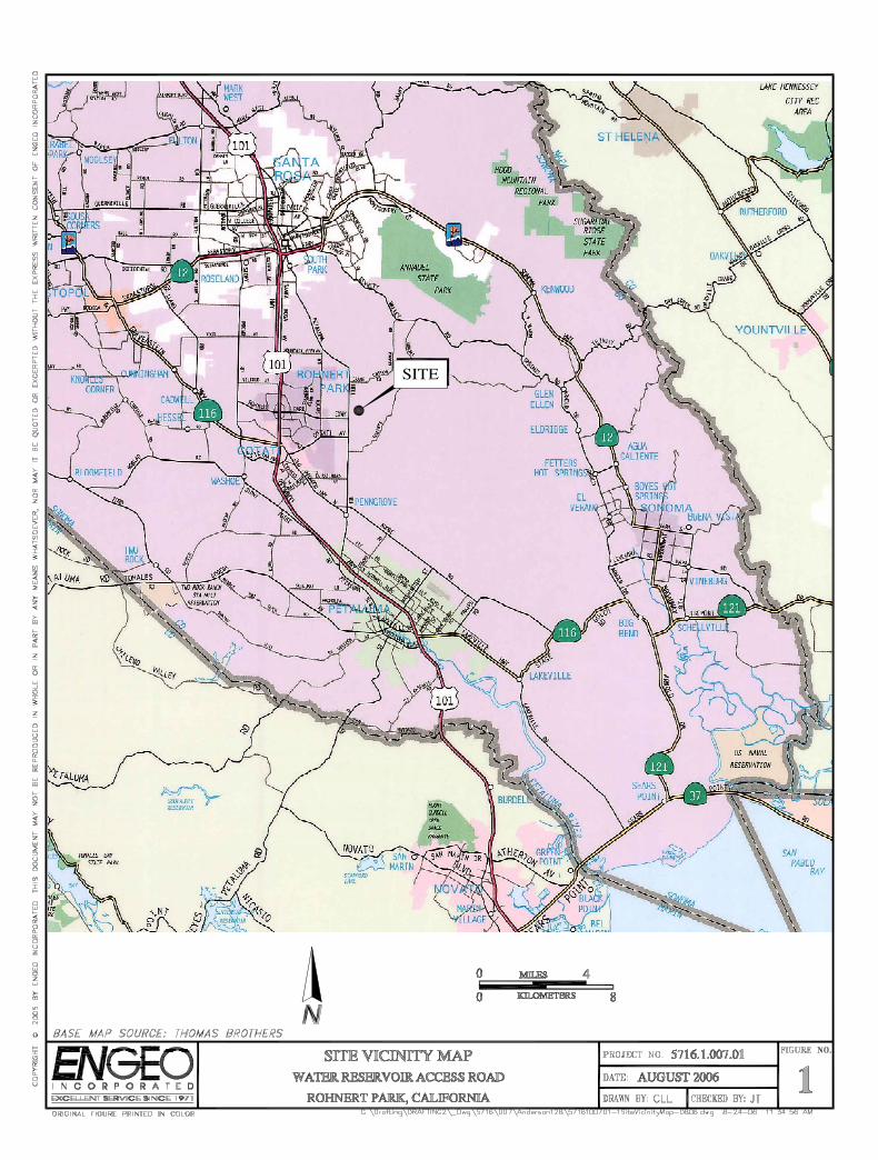
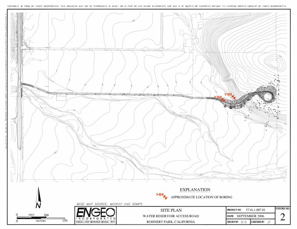
The study area is the central portion of an irregular shaped parcel located east of Petaluma Hill
Road, south of the Rohnert Park Expressway intersection in Rohnert Park, California (Figure 1).
The western edge of the 128-acre property is located along Petaluma Hill Road. The proposed
water reservoir access road will be located along the northern boundary of the site and connect
ENGEO INCORPORATED
5716.1.007.01 August 22, 2006 Revised September 28, 2006 2
Petaluma Hill Road with the proposed water reservoir site on a hillside in the eastern portion of the
property. A small unnamed drainage course crosses the propose road alignment near the base of the
eastern hillside. The site is currently undeveloped with vegetation that is generally composed of
grasses and brush.
Proposed Development
It is our understanding that the proposed access road will consist of an asphalt concrete and
all-weather surface road with associated underground utilities. A metal arch culvert is proposed at
the location of the drainage course. It is our understanding that the culvert will be supported by
13½-foot-wide spread footings, founded approximately 5 feet below the existing ground surface.
Construction of the proposed access road will include cuts and fill up to 16 feet.
ENGEO INCORPORATED
5716.1.007.01 August 22, 2006 Revised September 28, 2006 3
GEOLOGIC CONDITIONS
Site Geology
The site is located within the central part of the Coast Ranges Geomorphic Province of California.
Active faulting within the Coast Ranges has developed in response to complex interactions along the
transform boundary between the North American and Pacific tectonic plates. In general, the relative
motion along the boundary between the two plates is right-lateral strike-slip, with the Pacific Plate
moving northwestward with respect to the North American Plate. The San Andreas fault system,
defined as the San Andreas fault, as well as the associated strands that splay from it (i.e. the Rodgers
Creek, Tolay, Maacama, and Hayward faults, as well as others), is the main transform fault system
along this boundary and accommodates approximately 80 percent of the relative motion along the
broad boundary between the North American and Pacific plates (Argus and Gordon, 1991).
A published geologic map of the vicinity compiled by Fox (1973) indicates the site is depicted as
Tertiary andesitic to basaltic lava flows (Tsa) in the eastern area of the site that this report
addresses (Figure 2). The Quaternary deposits are shown as a centrally located
northeast-southwest trending belt of fan deposits (Qyf) consisting of fine sand and silt, with
gravel becoming more abundant toward the fan heads, with fluvial deposits (Qyfo), characterized
by fine sand, silt, and clay, depicted in the west site area.
Site Seismicity
No active faults are mapped across the project site by the California Division of Mines and
Geology (CDMG) or United States Geological Survey (USGS). The site is located in a region
that contains numerous active earthquake faults. No known faults cross the property and the nearest
ENGEO INCORPORATED
5716.1.007.01 August 22, 2006 Revised September 28, 2006 4
known active1 faults are the Rogers Creek fault located about 1½ miles east; Maacama fault located
about 16 miles northeast; the West Napa fault, about 16 miles to the east and the San Andreas
fault approximately 17 miles to the west of the site. The site is not located within a state-mandated
Earthquake Fault Zone.
Numerous small earthquakes occur every year in the San Francisco Bay Region, and larger
earthquakes have been recorded and can be expected to occur in the future. Figure 3 shows the
approximate locations of these faults and significant historic earthquakes recorded within the
San Francisco Bay Region.
1 An active fault is defined by the State Mining and Geology Board as one that has had surface displacement within Holocene time (about the last 10,000 years) (Hart, 1992).
ENGEO INCORPORATED
5716.1.007.01 August 22, 2006 Revised September 28, 2006 5
FIELD EXPLORATION
The field exploration for this study was conducted on March 14, 2005, and consisted of
two exploratory borings at the approximate locations shown on Figure 2. The locations were
selected based on the site accessibility and such that subsurface site conditions could be
determined in the area of the reservoir. The boring logs are included in this report (Appendix A).
The borings were performed using a CME 850 tracked rig and equipped with an 8-inch-diameter
hollow stem auger.
An ENGEO engineer logged the borings in the field and collected soil samples using either a
3.0-inch O.D. California-type split-spoon sampler fitted with 6-inch-long brass liners, or a 2-inch
O.D. Standard Penetration Test (SPT) split-spoon sampler. The samplers were advanced with an
automatic hammer. The penetration of the samplers into the native materials was field-recorded
as the number of blows needed to drive the sampler 18 inches in 6-inch increments. Blow count
results on the boring logs were recorded as the number of blows required for the last one foot of
penetration, or the distance indicated if driving refusal was encountered.
Subsurface Stratigraphy
The subsurface soils at the site generally consist of approximately interbedded medium dense to
dense sandy and gravelly soils. The site soils were underlain by Tertiary igneous bedrock which
primarily consist of andesitic to basaltic lava flows. The bedrock is friable to strong, closely to
moderately fractured, and deeply to moderately weathered.
ENGEO INCORPORATED
5716.1.007.01 August 22, 2006 Revised September 28, 2006 6
Groundwater Conditions
Groundwater was encountered in Boring 1-B4 at a depth of approximately 4 feet. Fluctuations in
groundwater levels may occur seasonally and over a period of years because of precipitation,
changes in drainage patterns, irrigation, and other factors.
ENGEO INCORPORATED
5716.1.007.01 August 22, 2006 Revised September 28, 2006 7
GEOLOGIC HAZARDS
Seismic Hazards
Seismic hazards can generally be classified as primary and secondary. The primary effect is
ground rupture, also called surface faulting. Common secondary seismic hazards include ground
shaking, lurch cracking, soil liquefaction, lateral spreading, landslides, and tsunamis and seiches.
The risk of regional subsidence/uplift, landslides, tsunamis or seiches is considered unlikely at
the site. The risk of earthquake-induced ground rupture, liquefaction, densification, lateral
spreading, and lurching are discussed below.
Ground Rupture. Since there are no known active faults crossing the site and the site is not
within a State of California Earthquake Fault Hazard Zone, the risk of ground rupture related to
faulting is considered remote.
Ground Shaking. An earthquake of moderate to high magnitude generated within the
San Francisco Bay Region could cause considerable ground shaking at the site. To mitigate the
shaking effects, all structures should be designed using sound engineering judgment and the
latest Uniform Building Code (UBC) requirements as a minimum (SEAOC, 1996). Deterministic
computer studies from current California fault data yield a mean horizontal bedrock acceleration of
0.55g from the nearby Rodgers Creek fault based on the attenuation relation by Idriss (1993).
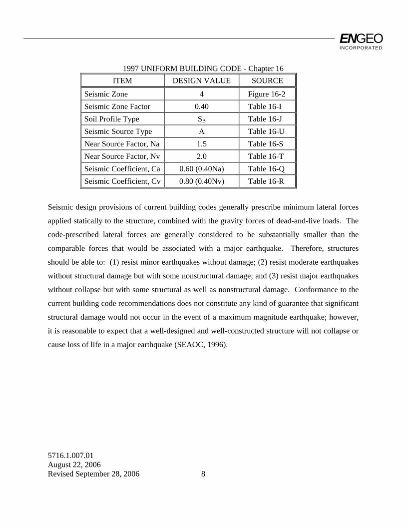
The near source factors, Na and Nv, are based on the Rodgers Creek fault being a seismic source
type A, approximately 1½ miles (2½ km) away. The UBC parameters for the reservoir design
are presented in the following table:
ENGEO INCORPORATED
5716.1.007.01 August 22, 2006 Revised September 28, 2006 8
1997 UNIFORM BUILDING CODE - Chapter 16 ITEM DESIGN VALUE SOURCE
Seismic Zone 4 Figure 16-2 Seismic Zone Factor 0.40 Table 16-I Soil Profile Type SB Table 16-J Seismic Source Type A Table 16-U Near Source Factor, Na 1.5 Table 16-S Near Source Factor, Nv 2.0 Table 16-T Seismic Coefficient, Ca 0.60 (0.40Na) Table 16-Q Seismic Coefficient, Cv 0.80 (0.40Nv) Table 16-R
Seismic design provisions of current building codes generally prescribe minimum lateral forces
applied statically to the structure, combined with the gravity forces of dead-and-live loads. The
code-prescribed lateral forces are generally considered to be substantially smaller than the
comparable forces that would be associated with a major earthquake. Therefore, structures
should be able to: (1) resist minor earthquakes without damage; (2) resist moderate earthquakes
without structural damage but with some nonstructural damage; and (3) resist major earthquakes
without collapse but with some structural as well as nonstructural damage. Conformance to the
current building code recommendations does not constitute any kind of guarantee that significant
structural damage would not occur in the event of a maximum magnitude earthquake; however,
it is reasonable to expect that a well-designed and well-constructed structure will not collapse or
cause loss of life in a major earthquake (SEAOC, 1996).
ENGEO INCORPORATED
5716.1.007.01 August 22, 2006 Revised September 28, 2006 9
CONCLUSIONS AND RECOMMENDATIONS
Based on our exploration, we conclude that the proposed water reservoir access road project is
feasible from a geotechnical standpoint. The primary geotechnical concern is the potential for
differential movement below the proposed culvert that crosses the unnamed drainage course at the
proposed site location. To minimize the potential impacts of the site materials, the proposed
reservoir tank access road and culvert should be designed in accordance with the recommendations
presented in this report.
Grading
Grading operations should meet the requirements of the Guide Contract Specifications included
in Appendix B and should be observed and tested by ENGEO's field representative. The
Geotechnical Engineer or qualified representative should be present during all phases of grading
operations to observe demolition, site preparation, grading operations, and subdrain placement. The
Geotechnical Engineer should be notified a minimum of 72 hours prior to the commencement of
any grading or stripping operations at the site. This is to provide time to coordinate the work with
the Grading Contractor.
Demolition and Stripping
All existing vegetation and soft or compressible soils in areas to be graded should be removed as
necessary for project requirements. The depth of removal of these materials should be
determined by the Geotechnical Engineer or qualified representative in the field at the time of
grading. Evaluation of unsuitable deposits should be performed during grading by sampling and
laboratory analyses.
ENGEO INCORPORATED
5716.1.007.01 August 22, 2006 Revised September 28, 2006 10
Construction areas receiving fill and those areas that serve as borrow for fill should be stripped of
existing vegetation. Actual depths will be determined by the Geotechnical Engineer or qualified
representative in the field during grading. Site strippings should be reserved for placement in
approved open space areas or landscape areas. Any topsoil retained for future use in landscape
areas should be approved by the Landscape Architect and stockpiled in areas where it will not
interfere with construction operations. Within the development areas, excavations resulting from
demolition, clearing, and/or stripping which extend below final grades should be cleaned to firm
undisturbed soil as determined by the Geotechnical Engineer's representative. All loose soil
material should be removed and recompacted.
Subgrade Preparation
After the site has been properly cleared, stripped and necessary excavations have been made, a
minimum of the upper 12 inches should be scarified, moisture conditioned, and compacted in
accordance with the recommendations presented below in the Fill Placement section.
Fill Materials
The site soils and bedrock are suitable to be reused as engineered fill provided these are processed
to meet the grading specification requirements. Import materials, if any are needed, must meet the
requirements contained in Section 2.02B, Part I of the Guide Contract Specifications. The
Geotechnical Engineer should be informed if any importation of soil is contemplated. A sample of
the proposed import material should be submitted to the Geotechnical Engineer for evaluation prior
to delivery at the site.
ENGEO INCORPORATED
5716.1.007.01 August 22, 2006 Revised September 28, 2006 11
Placement of Fill
With the exception of organically contaminated near-surface material, on-site soils containing
less than 3 percent organics are suitable for use as engineered fill. The following compaction
control requirements should be applied to all fills within the upper 5 feet of the site.
Test Procedures: ASTM D-1557 (latest edition).
Required Moisture Content: A minimum of 2 percentage points above optimum moisture content.
Minimum Relative Compaction: At least 90 percent relative compaction.
The following compaction control requirements should be applied to fills deeper than 5 feet and
within the upper 12 inches of all pavement subgrade and building pad areas:
Test Procedures: ASTM D-1557 (latest edition). Required Moisture Content: Above optimum moisture content.
Relative Compaction: A minimum of 95 percent relative compaction. All fills should be placed in thin lifts. The uncompacted lift thickness should not exceed
12 inches or the depth of penetration of the compaction equipment used, whichever is less. In
general, all site preparation and grading should be performed in accordance with the Contract
Guide Specifications presented in Appendix B. All site preparations for site grading should be
done under the observation of the Geotechnical Engineer or his/her qualified field representative.

ENGEO INCORPORATED
5716.1.007.01 August 22, 2006 Revised September 28, 2006 12
Graded Slopes
Cut and fill slopes can be constructed at an inclination of 2:1 (horizontal:vertical) without
intermediate benches. Slopes higher than 30 feet should be constructed at an inclination of 3:1 or
intermediate benches should be provide in accordance with the requirements of the 1997 Uniform
Building Code.
Foundation Design
As stated earlier, the proposed road crossing will be a steel multi-plate culvert. The footing
reinforcement should be designed by the structural engineer to accommodate the proposed use and
loading of the bridge structures. The culvert footings can be designed using an allowable bearing
pressure of 4,000 pounds per square foot (psf) for dead-plus-live loads on native soil or engineered
fill.
Footing trenches should be cleared of all loose materials, and soils exposed in footing
excavations should not be allowed to desiccate prior to placing concrete. Presoaking or
sprinkling of footing trenches may be required to reduce the potentially detrimental impact of
desiccation. The Geotechnical Engineer or his/her field representative should observe the
footing trenches prior to concrete placement.
Lateral Resistance. Lateral loads may be resisted by frictional resistance between the foundation
concrete and the subgrade soils and by passive earth pressure acting against the side of the
foundation. A coefficient of friction of 0.35 should be for lateral load resistance. In addition, an
allowable passive pressure based on an equivalent fluid weighing 350 pounds per cubic foot can
be used in design.
ENGEO INCORPORATED
5716.1.007.01 August 22, 2006 Revised September 28, 2006 13
Backfill Requirements. The backfill should conform, and be placed in accordance, with the culvert
manufacturer’s recommendations and the recommendations presented in the Fill Placement section
of this report. In addition, backfill soils should be placed on both sides of the culvert in a uniform
manner; at no time should there be greater than a 2 foot elevation difference between the backfill on
one side of the culvert versus the other side. Heavy compaction equipment should be limited as
specified by the manufacturer to prevent distortion and damage to the culvert.
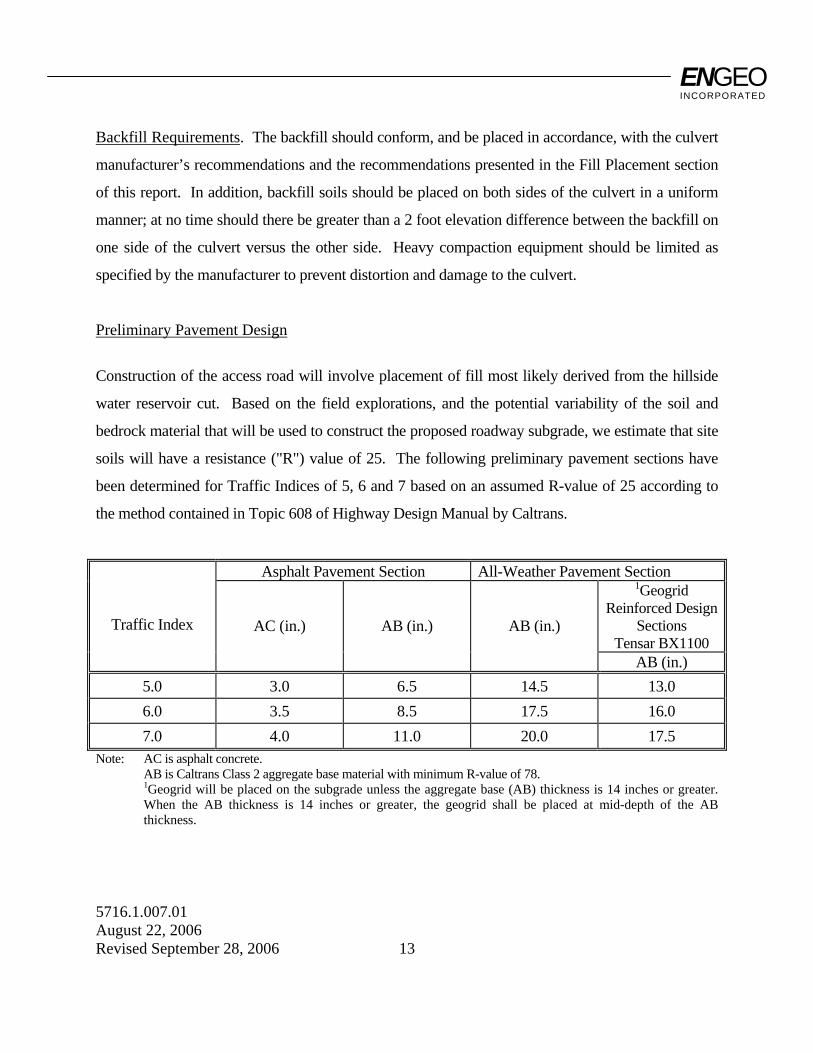
Preliminary Pavement Design
Construction of the access road will involve placement of fill most likely derived from the hillside
water reservoir cut. Based on the field explorations, and the potential variability of the soil and
bedrock material that will be used to construct the proposed roadway subgrade, we estimate that site
soils will have a resistance ("R") value of 25. The following preliminary pavement sections have
been determined for Traffic Indices of 5, 6 and 7 based on an assumed R-value of 25 according to
the method contained in Topic 608 of Highway Design Manual by Caltrans.
Asphalt Pavement Section All-Weather Pavement Section 1Geogrid
Reinforced Design Sections
Tensar BX1100
Traffic Index AC (in.) AB (in.) AB (in.)
AB (in.) 5.0 3.0 6.5 14.5 13.0 6.0 3.5 8.5 17.5 16.0 7.0 4.0 11.0 20.0 17.5
Note: AC is asphalt concrete. AB is Caltrans Class 2 aggregate base material with minimum R-value of 78. 1Geogrid will be placed on the subgrade unless the aggregate base (AB) thickness is 14 inches or greater.
When the AB thickness is 14 inches or greater, the geogrid shall be placed at mid-depth of the AB thickness.
ENGEO INCORPORATED
5716.1.007.01 August 22, 2006 Revised September 28, 2006 14
The Traffic Index should be determined by the Civil Engineer or appropriate public agency. These
sections are for estimating purposes only. Actual sections to be used should be based on R-value
tests performed on samples of actual subgrade materials recovered at the time of grading. Pavement
construction and all materials should comply with the requirements of the Standard Specifications
of the State of California Division of Highways, County requirements and the following minimum
requirements.
• All pavement subgrades should be scarified to a depth of 12 inches (30 centimeters) below finished subgrade elevation, moisture conditioned to 2 percentage points above optimum, and compacted to at least 92 percent relative compaction and in accordance with County requirements.
• Subgrade soils should be in a stable, non-pumping condition at the time aggregate baserock
materials are placed and compacted. • Adequate provisions must be made such that the subgrade soils and aggregate baserock
materials are not allowed to become saturated. • Aggregate baserock materials should meet current Caltrans specifications for Class 2 aggregate
baserock and should be compacted to at least 95 percent of maximum dry density at a minimum moisture content of optimum.
• Asphalt paving materials should meet current Caltrans specifications for asphalt concrete. • All concrete curbs separating pavement and irrigated landscaped areas should extend into the
subgrade and below the bottom of adjacent aggregate baserock materials.
Utilities
It is recommended that all utility trench backfill be done under the observation of a Geotechnical
Engineer. Pipe zone backfill (i.e. material beneath and immediately surrounding the pipe) may
consist of a well-graded import or native material less than ¾ inch (2 centimeters) in maximum
dimension. Trench zone backfill (i.e. material placed between the pipe zone backfill and the
ENGEO INCORPORATED
5716.1.007.01 August 22, 2006 Revised September 28, 2006 15
ground surface) may consist of native soil compacted in accordance with recommendations for
engineered fill.
Where import material is used for pipe zone backfill, we recommend that it consist of fine- to
medium-grained sand or a well-graded mixture of sand and gravel and that this material not be used
within 2 feet of finish grades. In general, uniformly graded gravel should not be used for pipe or
trench zone backfill due to the potential for migration of (1) soil into the relatively large void spaces
present in this type of material; and (2) water along trenches backfilled with this type of material.
All utility trenches entering buildings and paved areas must be provided with an impervious seal
consisting of native materials or concrete where the trenches pass under structure perimeters or curb
lines. The impervious plug should extend at least 3 feet (1 meter) to either side of the crossing.
This is to prevent surface water percolation into the sands under foundations and pavements where
such water would remain trapped in a perched condition, allowing clays to develop their full
expansion potential.
Utility trenches should not be located upslope of any foundation area unless the placement, depth,
and backfill material to be used are reviewed by the Geotechnical Engineer. Care should be
exercised where utility trenches are located beside foundation areas. Utility trenches constructed
parallel to foundations should be located entirely above a plane extending down from the lower
edge of the footing at an angle of 45 degrees. Utility companies and Landscape Architects should
be made aware of this information.
Utility trenches in areas to be paved should be backfilled to the specifications provided in this report
for engineered fill. Compaction of trench backfill by jetting shall not be allowed at this site.
ENGEO INCORPORATED
5716.1.007.01 August 22, 2006 Revised September 28, 2006 16
LIMITATIONS AND UNIFORMITY OF CONDITIONS
This geotechnical report is issued with the understanding that it is the responsibility of the owner to
transmit the information and recommendations of this report to developers, contractors, buyers,
architects, engineers, and designers for the project so that the necessary steps can be taken by the
contractors and subcontractors to carry out such recommendations in the field. The conclusions and
recommendations contained in this report are solely professional opinions.
The professional staff of ENGEO Incorporated strives to perform its services in a proper and
professional manner with reasonable care and competence but is not infallible. There are risks of
earth movement and property damages inherent in land development. We are unable to eliminate
all risks or provide insurance; therefore, we are unable to guarantee or warrant the results of our
work.
This report is based upon field and other conditions discovered at the time of preparation of
ENGEO's work. This document must not be subject to unauthorized reuse, that is, reuse without
written authorization of ENGEO. Such authorization is essential because it requires ENGEO to
evaluate the document's applicability given new circumstances, not the least of which is passage of
time. Actual field or other conditions will necessitate clarifications, adjustments, modifications or
other changes to ENGEO's work. Therefore, ENGEO must be engaged to prepare the necessary
clarifications, adjustments, modifications or other changes before construction activities commence
or further activity proceeds. If ENGEO's scope of services does not include on-site construction
observation, or if other persons or entities are retained to provide such services, ENGEO cannot be
held responsible for any or all claims, including, but not limited to claims arising from or resulting
from the performance of such services by other persons or entities, and any or all claims arising
from or resulting from clarifications, adjustments, modifications, discrepancies or other changes
necessary to reflect changed field or other conditions.
ENGEO INCORPORATED
5716.1.007.01 August 22, 2006 Revised September 28, 2006
SELECTED REFERENCES
Argus, D. F., and R. G. Gordon, Current Sierra Nevada-North America motion from very long
baseline inferometery: implications for the kinematics of the western United States, Geology, 19, 1085-1088, 1991.
Bortugno, E. J.; et al, 1982, Map Showing Recency of Faulting, Santa Rosa Quadrangle USGS
Map Sheet 2. Fox, K. F., Jr., Sims, J. D., Bartow, J., A., and Helley, E., J., 1973, Preliminary Geologic Map of
Eastern Sonoma County and Western Napa County, U.S. Geologic Survey, Open-file Report. Idriss, I. M., 1993, Procedures for Selecting Earthquake Ground Motions at Rock Sites: Report to
the National Institute of Standards and Technology, United States Department of Commerce. SEAOC; 1996, Recommended Lateral Force Requirements and Tentative Commentary. State of California; 1982, Tolay Fault -- Fault Evaluation Report, FER 140. State of California; 1983, Special Studies Zone Map, Cotati Quadrangle, Sonoma County,
California. Thomas, D.B.. Abt, S.R., Mussetter, R.A. and Harvey, M.D., 2000. A Design Procedure for
Sizing Step-Pool Structures, Proceedings from the ASCE Water Resources Conference. USGS; 2003, Earthquake Probabilities in the San Francisco Bay Region: 2002–2031, Working
Group On California Earthquake Probabilities; Open-File Report 03-214.

ENGEO INCORPORATED
5716.1.007.01 August 22, 2006 Revised September 28, 2006
LIST OF FIGURES
Figure 1 Site Vicinity Map Figure 2 Site Map
ENGEO INCORPORATED
5716.1.007.01 August 22, 2006 Revised September 28, 2006
APPENDIX A
Boring Logs
SILTS AND CLAYS LIQUID LIMIT GREATER THAN 50 %
SILTS AND CLAYS LIQUID LIMIT 50 % OR LESS
CO
AR
SE
-GR
AIN
ED
SO
ILS
MO
RE
TH
AN
HA
LF O
F M
AT'L
LA
RG
ER
TH
AN
#20
0S
IEV
E
FIN
E-G
RA
INE
D S
OIL
S M
OR
ETH
AN
HA
LF O
F M
AT'L
SM
ALL
ER
THA
N #
200
SIE
VE
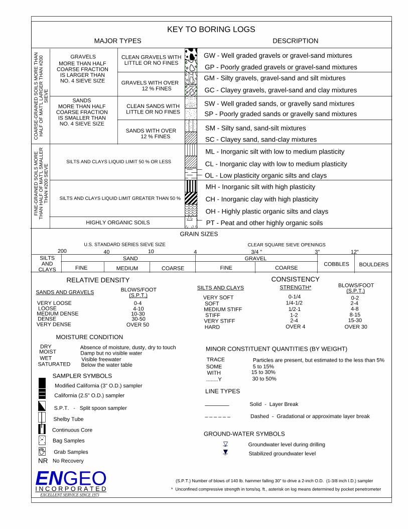
DESCRIPTION
STRENGTH*
OVER 4
0-2
MOISTURE CONDITION
MINOR CONSTITUENT QUANTITIES (BY WEIGHT)
TRACE Particles are present, but estimated to the less than 5%5 to 15%
15 to 30%
CLEAN SANDS WITHLITTLE OR NO FINES
4-10
GP - Poorly graded gravels or gravel-sand mixtures
STIFF
SANDS AND GRAVELS
VERY LOOSE
GM - Silty gravels, gravel-sand and silt mixtures
GC - Clayey gravels, gravel-sand and clay mixtures
SW - Well graded sands, or gravelly sand mixturesSP - Poorly graded sands or gravelly sand mixtures
CL - Inorganic clay with low to medium plasticity
GRAVELS
GRAVELS WITH OVER 12 % FINES
SILTSAND
CLAYS
BLOWS/FOOT(S.P.T.)
SAMPLER SYMBOLS
CONSISTENCY
U.S. STANDARD SERIES SIEVE SIZE CLEAR SQUARE SIEVE OPENINGS
SM - Silty sand, sand-silt mixtures
3/4 "
ENGEO
HIGHLY ORGANIC SOILS
(S.P.T.) VERY SOFTSOFT
SILTS AND CLAYS
MEDIUM DENSE
California (2.5" O.D.) sampler
DENSEVERY DENSE
200 40
VERY STIFFHARD
10 4
MAJOR TYPES
GW - Well graded gravels or gravel-sand mixtures
SC - Clayey sand, sand-clay mixtures
OL - Low plasticity organic silts and clays
MH - Inorganic silt with high plasticity
CH - Inorganic clay with high plasticity
OH - Highly plastic organic silts and clays
FINE
RELATIVE DENSITYBLOWS/FOOT
0-4
10-3030-50
OVER 50
MORE THAN HALFCOARSE FRACTION
IS LARGER THANNO. 4 SIEVE SIZE
GRAIN SIZES
2-44-88-15
15-30OVER 30
KEY TO BORING LOGS
1/2-1
SANDS WITH OVER 12 % FINES
MEDIUM STIFF
0-1/41/4-1/2
COARSEMEDIUM
SANDSMORE THAN HALF
COARSE FRACTIONIS SMALLER THANNO. 4 SIEVE SIZE
1-22-4
3" 12"
LOOSE
CLEAN GRAVELS WITHLITTLE OR NO FINES
BOULDERSCOBBLESCOARSEFINE
Modified California (3" O.D.) sampler
(S.P.T.) Number of blows of 140 lb. hammer falling 30" to drive a 2-inch O.D. (1-3/8 inch I.D.) sampler
* Unconfined compressive strength in tons/sq. ft., asterisk on log means determined by pocket penetrometer
SOMEWITH
S.P.T. - Split spoon sampler
Shelby Tube
Continuous Core
NR
Bag Samples
No RecoveryGrab Samples
I N C O R P O R A T E D
PT - Peat and other highly organic soils
ML - Inorganic silt with low to medium plasticity
SAND GRAVEL
EXCELLENT SERVICE SINCE 1971
DRY Absence of moisture, dusty, dry to touchDamp but no visible waterMOISTVisible freewaterWET
SATURATED Below the water table
........Y 30 to 50%
LINE TYPES
Solid - Layer Break
_ _ _ _ _ _ Dashed - Gradational or approximate layer break
GROUND-WATER SYMBOLS
Groundwater level during drilling
Stabilized groundwater level
08
-23
-20
06
G
:\A
ctive
Pro
jects
\57
16
\57
16
10
07
01
\Lo
gs\B
-1_
co
relo
g.b
or
Depth
in F
eet
0
5
10
15
20
25
30
Depth
in M
ete
rs
0
1
2
3
4
5
6
7
8
9
DESCRIPTION
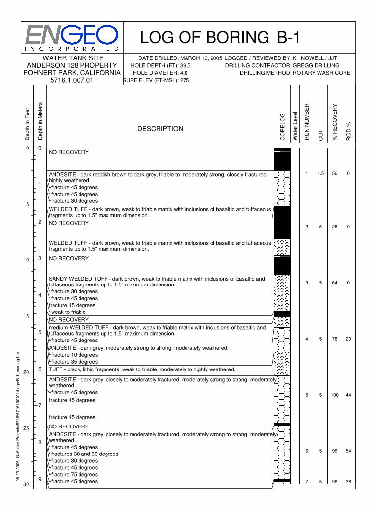
NO RECOVERY
ANDESITE - dark reddish brown to dark grey, friable to moderately strong, closely fractured, highly weathered.
fracture 45 degrees
fracture 45 degrees
fracture 30 degrees
WELDED TUFF - dark brown, weak to friable matrix with inclusions of basaltic and tuffaceous fragments up to 1.5" maximum dimension.
NO RECOVERY
WELDED TUFF - dark brown, weak to friable matrix with inclusions of basaltic and tuffaceous fragments up to 1.5" maximum dimension.
NO RECOVERY
SANDY WELDED TUFF - dark brown, weak to friable matrix with inclusions of basaltic and tuffaceous fragments up to 1.5" maximum dimension.
fracture 30 degrees
fracture 45 degrees
fracture 45 degrees
weak to friable
NO RECOVERY
medium-WELDED TUFF - dark brown, weak to friable matrix with inclusions of basaltic and tuffaceous fragments up to 1.5" maximum dimension.
fracture 45 degrees
ANDESITE - dark grey, moderately strong to strong, moderately weathered.
fracture 10 degrees
fracture 35 degrees
TUFF - black, lithic fragments, weak to friable, moderately to highly weathered.
ANDESITE - dark grey, closely to moderately fractured, moderately strong to strong, moderately weathered.
fracture 45 degrees
fracture 45 degrees
fracture 45 degrees
NO RECOVERY
ANDESITE - dark grey, closely to moderately fractured, moderately strong to strong, moderately weathered.
fracture 45 degrees
fractures 30 and 60 degrees
fracture 30 degrees
fracture 45 degrees
fracture 75 degrees
fracture 45 degrees
CO
RE
LO
G
Wate
r Level
RU
N N
UM
BE
R
1
2
3
4
5
6
7
CU
T
4.5
5
5
5
5
5
5
% R
EC
OV
ER
Y
56
28
64
78
100
96
96
RQ
D %
0
0
0
20
44
54
36
LOG OF BORINGDATE DRILLED:
HOLE DEPTH (FT):
HOLE DIAMETER:
SURF ELEV (FT-MSL):
LOGGED / REVIEWED BY:
DRILLING CONTRACTOR:
DRILLING METHOD:
WATER TANK SITEANDERSON 128 PROPERTY
ROHNERT PARK, CALIFORNIA5716.1.007.01
MARCH 10, 2005
39.5
4.0
275
K. NOWELL / JJT
GREGG DRILLING
ROTARY WASH CORE
B-1
08
-23
-20
06
G
:\A
ctive
Pro
jects
\57
16
\57
16
10
07
01
\Lo
gs\B
-1_
co
relo
g.b
or
Depth
in F
eet
30
35
40
45
50
55
60
Depth
in M
ete
rs
10
11
12
13
14
15
16
17
18
19
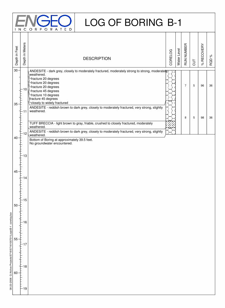
DESCRIPTION
ANDESITE - dark grey, closely to moderately fractured, moderately strong to strong, moderately weathered.
fracture 20 degrees
fracture 20 degrees
fracture 20 degrees
fracture 45 degrees
fracture 10 degreesfracture 45 degrees
closely to widely fractured
ANDESITE - reddish brown to dark grey, closely to moderately fractured, very strong, slightly weathered.
TUFF BRECCIA - light brown to gray, friable, crushed to closely fractured, moderately weathered.
ANDESITE - reddish brown to dark grey, closely to moderately fractured, very strong, slightly weathered.
Bottom of Boring at approximately 39.5 feet.No groundwater encountered.
CO
RE
LO
G
Wate
r Level
RU
N N
UM
BE
R
7
8
CU
T
5
5
% R
EC
OV
ER
Y
96
98
RQ
D %
36
36
LOG OF BORING B-1
08
-23
-20
06
G
:\A
ctive
Pro
jects
\57
16
\57
16
10
07
01
\Lo
gs\B
-2_
co
relo
g.b
or
Depth
in F
eet
0
5
10
15
20
25
30
Depth
in M
ete
rs
0
1
2
3
4
5
6
7
8
9
DESCRIPTION
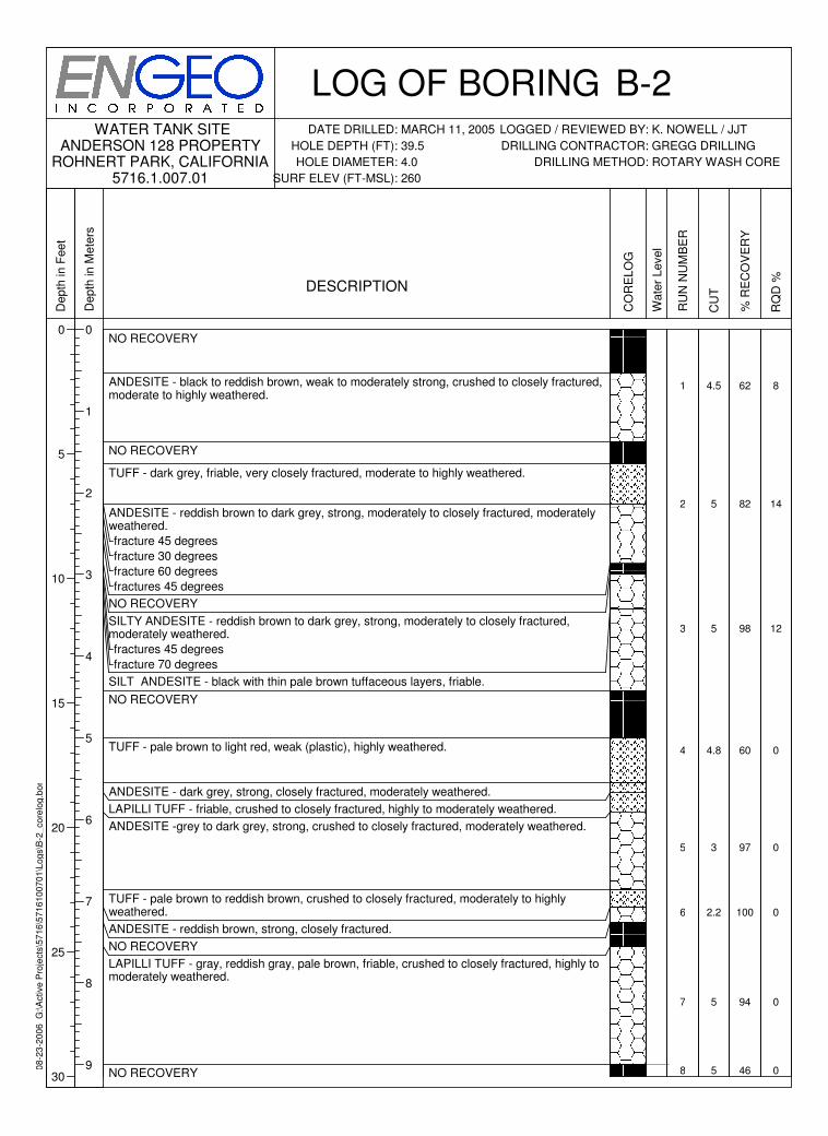
NO RECOVERY
ANDESITE - black to reddish brown, weak to moderately strong, crushed to closely fractured, moderate to highly weathered.
NO RECOVERY
TUFF - dark grey, friable, very closely fractured, moderate to highly weathered.
ANDESITE - reddish brown to dark grey, strong, moderately to closely fractured, moderately weathered.
fracture 45 degrees
fracture 30 degrees
fracture 60 degrees
fractures 45 degrees
NO RECOVERY
SILTY ANDESITE - reddish brown to dark grey, strong, moderately to closely fractured, moderately weathered.
fractures 45 degrees
fracture 70 degrees
SILT ANDESITE - black with thin pale brown tuffaceous layers, friable.
NO RECOVERY
TUFF - pale brown to light red, weak (plastic), highly weathered.
ANDESITE - dark grey, strong, closely fractured, moderately weathered.
LAPILLI TUFF - friable, crushed to closely fractured, highly to moderately weathered.
ANDESITE -grey to dark grey, strong, crushed to closely fractured, moderately weathered.
TUFF - pale brown to reddish brown, crushed to closely fractured, moderately to highly weathered.
ANDESITE - reddish brown, strong, closely fractured.
NO RECOVERY
LAPILLI TUFF - gray, reddish gray, pale brown, friable, crushed to closely fractured, highly to moderately weathered.
NO RECOVERY
CO
RE
LO
G
Wate
r Level
RU
N N
UM
BE
R
1
2
3
4
5
6
7
8
CU
T
4.5
5
5
4.8
3
2.2
5
5
% R
EC
OV
ER
Y
62
82
98
60
97
100
94
46
RQ
D %
8
14
12
0
0
0
0
0
LOG OF BORINGDATE DRILLED:
HOLE DEPTH (FT):
HOLE DIAMETER:
SURF ELEV (FT-MSL):
LOGGED / REVIEWED BY:
DRILLING CONTRACTOR:
DRILLING METHOD:
WATER TANK SITEANDERSON 128 PROPERTY
ROHNERT PARK, CALIFORNIA5716.1.007.01
MARCH 11, 2005
39.5
4.0
260
K. NOWELL / JJT
GREGG DRILLING
ROTARY WASH CORE
B-2
08
-23
-20
06
G
:\A
ctive
Pro
jects
\57
16
\57
16
10
07
01
\Lo
gs\B
-2_
co
relo
g.b
or
Depth
in F
eet
30
35
40
45
50
55
60
Depth
in M
ete
rs
10
11
12
13
14
15
16
17
18
19
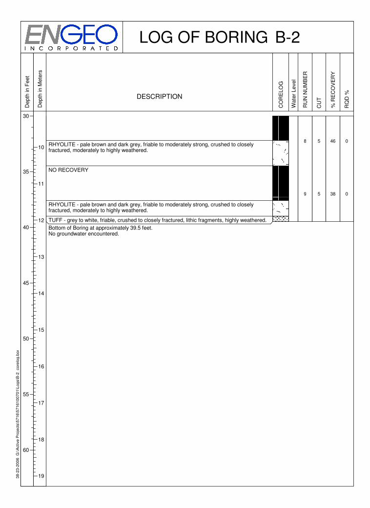
DESCRIPTION
RHYOLITE - pale brown and dark grey, friable to moderately strong, crushed to closely fractured, moderately to highly weathered.
NO RECOVERY
RHYOLITE - pale brown and dark grey, friable to moderately strong, crushed to closely fractured, moderately to highly weathered.
TUFF - grey to white, friable, crushed to closely fractured, lithic fragments, highly weathered.
Bottom of Boring at approximately 39.5 feet.No groundwater encountered.
CO
RE
LO
G
Wate
r Level
RU
N N
UM
BE
R
8
9
CU
T
5
5
% R
EC
OV
ER
Y
46
38
RQ
D %
0
0
LOG OF BORING B-2
08
-23
-20
06
G
:\A
ctive
Pro
jects
\57
16
\57
16
10
07
01
\Lo
gs\B
-3_
Ta
nksite
.bo
r
Depth
in F
eet
0
5
10
15
20
25
30
35
Depth
in M
ete
rs
0
1
2
3
4
5
6
7
8
9
10
Sam
ple
Type
DESCRIPTION
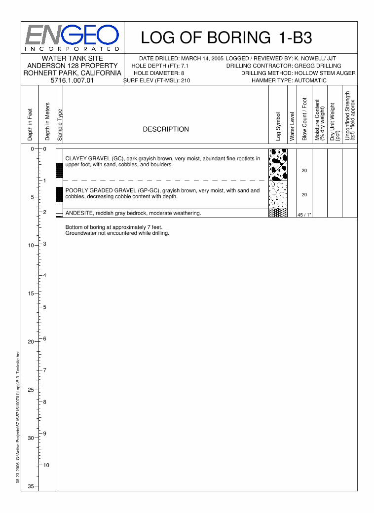
CLAYEY GRAVEL (GC), dark grayish brown, very moist, abundant fine rootlets in upper foot, with sand, cobbles, and boulders.
POORLY GRADED GRAVEL (GP-GC), grayish brown, very moist, with sand and cobbles, decreasing cobble content with depth.
ANDESITE, reddish gray bedrock, moderate weathering.
Bottom of boring at approximately 7 feet. Groundwater not encountered while drilling.
Log S
ym
bol
Wate
r Level
Blo
w C
ount / F
oot
20
20
45 / 1"
Mois
ture
Conte
nt
(% d
ry w
eig
ht)
Dry
Unit W
eig
ht
(pcf)
Unconfined S
trength
(tsf)
*field
appro
x
LOG OF BORINGDATE DRILLED:
HOLE DEPTH (FT):
HOLE DIAMETER:
SURF ELEV (FT-MSL):
LOGGED / REVIEWED BY:
DRILLING CONTRACTOR:
DRILLING METHOD:
HAMMER TYPE:
WATER TANK SITEANDERSON 128 PROPERTY
ROHNERT PARK, CALIFORNIA5716.1.007.01 AUTOMATIC
MARCH 14, 2005
7.1
8
210
K. NOWELL/ JJT
GREGG DRILLING
HOLLOW STEM AUGER
1-B3
08
-23
-20
06
G
:\A
ctive
Pro
jects
\57
16
\57
16
10
07
01
\Lo
gs\B
-4_
Ta
nksite
.bo
r
Depth
in F
eet
0
5
10
15
20
25
30
35
Depth
in M
ete
rs
0
1
2
3
4
5
6
7
8
9
10
Sam
ple
Type
DESCRIPTION
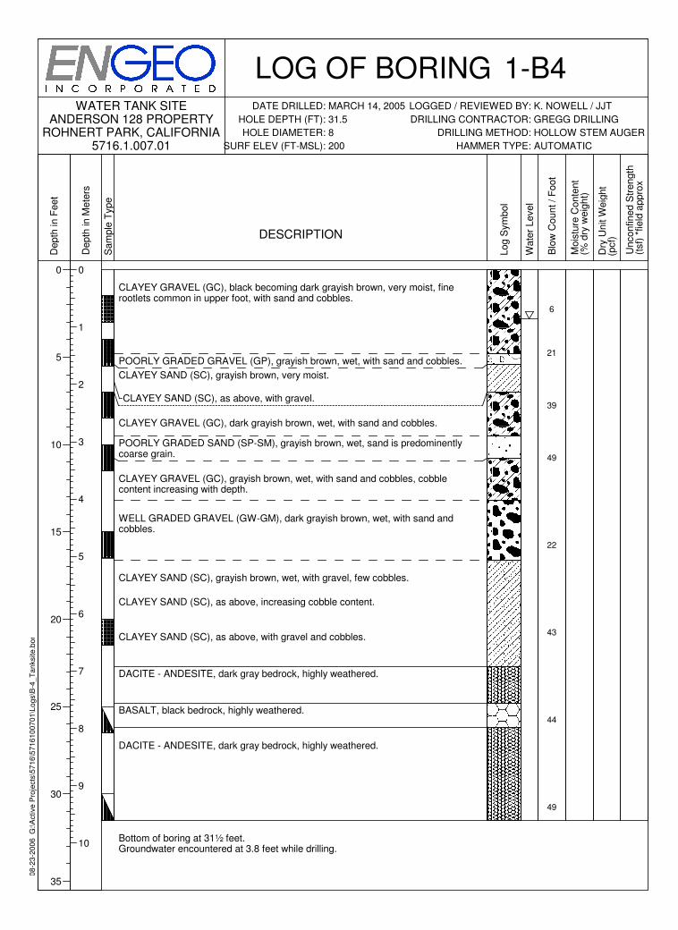
CLAYEY GRAVEL (GC), black becoming dark grayish brown, very moist, fine rootlets common in upper foot, with sand and cobbles.
POORLY GRADED GRAVEL (GP), grayish brown, wet, with sand and cobbles.
CLAYEY SAND (SC), grayish brown, very moist.
CLAYEY SAND (SC), as above, with gravel.
CLAYEY GRAVEL (GC), dark grayish brown, wet, with sand and cobbles.
POORLY GRADED SAND (SP-SM), grayish brown, wet, sand is predominently coarse grain.
CLAYEY GRAVEL (GC), grayish brown, wet, with sand and cobbles, cobble content increasing with depth.
WELL GRADED GRAVEL (GW-GM), dark grayish brown, wet, with sand and cobbles.
CLAYEY SAND (SC), grayish brown, wet, with gravel, few cobbles.
CLAYEY SAND (SC), as above, increasing cobble content.
CLAYEY SAND (SC), as above, with gravel and cobbles.
DACITE - ANDESITE, dark gray bedrock, highly weathered.
BASALT, black bedrock, highly weathered.
DACITE - ANDESITE, dark gray bedrock, highly weathered.
Bottom of boring at 31½ feet. Groundwater encountered at 3.8 feet while drilling.
Log S
ym
bol
Wate
r Level
Blo
w C
ount / F
oot
6
21
39
49
22
43
44
49
Mois
ture
Conte
nt
(% d
ry w
eig
ht)
Dry
Unit W
eig
ht
(pcf)
Unconfined S
trength
(tsf)
*field
appro
x
LOG OF BORINGDATE DRILLED:
HOLE DEPTH (FT):
HOLE DIAMETER:
SURF ELEV (FT-MSL):
LOGGED / REVIEWED BY:
DRILLING CONTRACTOR:
DRILLING METHOD:
HAMMER TYPE:
WATER TANK SITEANDERSON 128 PROPERTY
ROHNERT PARK, CALIFORNIA5716.1.007.01 AUTOMATIC
MARCH 14, 2005
31.5
8
200
K. NOWELL / JJT
GREGG DRILLING
HOLLOW STEM AUGER
1-B4
ENGEO INCORPORATED
5716.1.007.01 August 22, 2006 Revised September 28, 2006
APPENDIX B
Contract Guide Specifications
ENGEO INCORPORATED
5716.1.007.01 August 22, 2006 Revised September 28, 2006 1
GUIDE CONTRACT SPECIFICATIONS PART I - EARTHWORK PREFACE These specifications are intended as a guide for the earthwork performed at the subject development project. If there is a conflict between these specifications (including the recommendations of the geotechnical report) and agency or code requirements, it should be brought to the attention of ENGEO and Owner prior to contract bidding. PART 1 - GENERAL 1.01 WORK COVERED A. Grading, excavating, filling and backfilling, including trenching and backfilling for
utilities as necessary to complete the Project as indicated on the Drawings. B. Subsurface drainage as indicated on the Drawings. 1.02 CODES AND STANDARDS A. Excavating, trenching, filling, backfilling, and grading work shall meet the applicable
requirements of the Uniform Building Code and the standards and ordinances of state and local governing authorities.
1.03 SUBSURFACE SOIL CONDITIONS A. The Owners' Geotechnical Exploration report is available for inspection by bidder or
Contractor. The Contractor shall refer to the findings and recommendations of the Geotechnical Exploration report in planning and executing his work.
1.04 DEFINITIONS A. Fill: All soil, rock, or soil-rock materials placed to raise the grades of the site or to
backfill excavations. B. Backfill: All soil, rock or soil-rock material used to fill excavations and trenches. C. On-Site Material: Soil and/or rock material which is obtained from the site.
ENGEO INCORPORATED
5716.1.007.01 August 22, 2006 Revised September 28, 2006 2
D. Imported Material: Soil and/or rock material which is brought to the site from off-site
areas. E. Select Material: On-site and/or imported material which is approved by ENGEO as a
specific-purpose fill. F. Engineered Fill: Fill upon which ENGEO has made sufficient observations and tests
to confirm that the fill has been placed and compacted in accordance with specifications and requirements.
G. Degree of Compaction or Relative Compaction: The ratio, expressed as a percentage,
of the in-place dry density of the fill and backfill material as compacted in the field to the maximum dry density of the same material as determined by ASTM D-1557 or California 216 compaction test method.
H. Optimum Moisture: Water content, percentage by dry weight, corresponding to the
maximum dry density as determined by ASTM D-1557. I. ENGEO: The project geotechnical engineering consulting firm, its employees or its
designated representatives. J. Drawings: All documents, approved for construction, which describe the Work. 1.05 OBSERVATION AND TESTING A. All site preparation, cutting and shaping, excavating, filling, and backfilling shall be
carried out under the observation of ENGEO, employed and paid for by the Owners. ENGEO will perform appropriate field and laboratory tests to evaluate the suitability of fill material, the proper moisture content for compaction, and the degree of compaction achieved. Any fill that does not meet the specification requirements shall be removed and/or reworked until the requirements are satisfied.
B. Cutting and shaping, excavating, conditioning, filling, and compacting procedures
require approval of ENGEO as they are performed. Any work found unsatisfactory or any work disturbed by subsequent operations before approval is granted shall be corrected in an approved manner as recommended by ENGEO.
C. Tests for compaction will be made in accordance with test procedures outlined in
ASTM D-1557, as applicable. Field testing of soils or compacted fill shall conform with the applicable requirements of ASTM D-2922.

ENGEO INCORPORATED
5716.1.007.01 August 22, 2006 Revised September 28, 2006 3
D. All authorized observation and testing will be paid for by the Owners. 1.06 SITE CONDITIONS A. Excavating, filling, backfilling, and grading work shall not be performed during
unfavorable weather conditions. When the work is interrupted by rain, excavating, filling, backfilling, and grading work shall not be resumed until the site and soil conditions are suitable.
B. Contractor shall take the necessary measures to prevent erosion of freshly filled,
backfilled, and graded areas until such time as permanent drainage and erosion control measures have been installed.
PART 2 - PRODUCTS 2.01 GENERAL A. Contractor shall furnish all materials, tools, equipment, facilities, and services as
required for performing the required excavating, filling, backfilling, and grading work, and trenching and backfilling for utilities.
2.02 SOIL MATERIALS A. Fill 1. Material to be used for engineered fill and backfill shall be free from organic
matter and other deleterious substances, and of such quality that it will compact thoroughly without excessive voids when watered and rolled. Excavated on-site material will be considered suitable for engineered fill and backfill if it contains no more than 3 percent organic matter, is free of debris and other deleterious substances and conforms to the requirements specified above. Rocks of maximum dimension in excess of two-thirds of the lift thickness shall be removed from any fill material to the satisfaction of ENGEO.
2. Excavated earth material which is suitable for engineered fill or backfill, as
determined by ENGEO, shall be conditioned for reuse and properly stockpiled as required for later filling and backfilling operations. Conditioning shall consist of spreading material in layers not to exceed 8 inches and raking free of debris and rubble. Rocks and aggregate exceeding the allowed largest dimension, and deleterious material shall be removed from the site and disposed off site in a legal manner.
ENGEO INCORPORATED
5716.1.007.01 August 22, 2006 Revised September 28, 2006 4
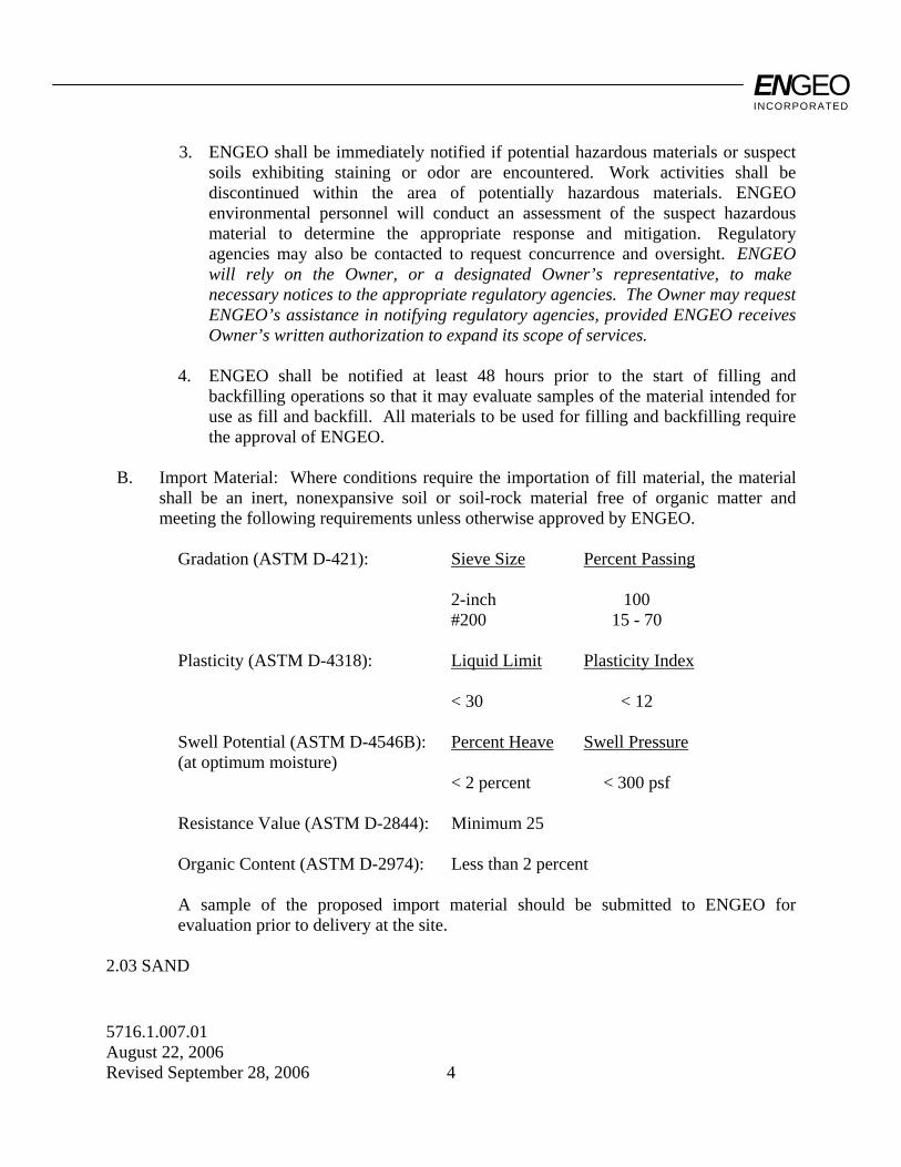
3. ENGEO shall be immediately notified if potential hazardous materials or suspect soils exhibiting staining or odor are encountered. Work activities shall be discontinued within the area of potentially hazardous materials. ENGEO environmental personnel will conduct an assessment of the suspect hazardous material to determine the appropriate response and mitigation. Regulatory agencies may also be contacted to request concurrence and oversight. ENGEO will rely on the Owner, or a designated Owner’s representative, to make necessary notices to the appropriate regulatory agencies. The Owner may request ENGEO’s assistance in notifying regulatory agencies, provided ENGEO receives Owner’s written authorization to expand its scope of services.
4. ENGEO shall be notified at least 48 hours prior to the start of filling and
backfilling operations so that it may evaluate samples of the material intended for use as fill and backfill. All materials to be used for filling and backfilling require the approval of ENGEO.
B. Import Material: Where conditions require the importation of fill material, the material
shall be an inert, nonexpansive soil or soil-rock material free of organic matter and meeting the following requirements unless otherwise approved by ENGEO.
Gradation (ASTM D-421): Sieve Size Percent Passing 2-inch 100 #200 15 - 70 Plasticity (ASTM D-4318): Liquid Limit Plasticity Index < 30 < 12 Swell Potential (ASTM D-4546B): Percent Heave Swell Pressure (at optimum moisture) < 2 percent < 300 psf Resistance Value (ASTM D-2844): Minimum 25 Organic Content (ASTM D-2974): Less than 2 percent A sample of the proposed import material should be submitted to ENGEO for
evaluation prior to delivery at the site. 2.03 SAND
ENGEO INCORPORATED
5716.1.007.01 August 22, 2006 Revised September 28, 2006 5
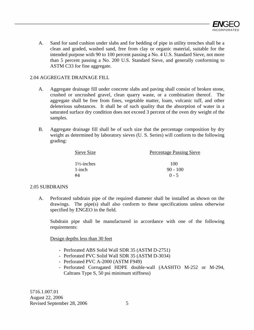
A. Sand for sand cushion under slabs and for bedding of pipe in utility trenches shall be a clean and graded, washed sand, free from clay or organic material, suitable for the intended purpose with 90 to 100 percent passing a No. 4 U.S. Standard Sieve, not more than 5 percent passing a No. 200 U.S. Standard Sieve, and generally conforming to ASTM C33 for fine aggregate.
2.04 AGGREGATE DRAINAGE FILL A. Aggregate drainage fill under concrete slabs and paving shall consist of broken stone,
crushed or uncrushed gravel, clean quarry waste, or a combination thereof. The aggregate shall be free from fines, vegetable matter, loam, volcanic tuff, and other deleterious substances. It shall be of such quality that the absorption of water in a saturated surface dry condition does not exceed 3 percent of the oven dry weight of the samples.
B. Aggregate drainage fill shall be of such size that the percentage composition by dry
weight as determined by laboratory sieves (U. S. Series) will conform to the following grading:
Sieve Size Percentage Passing Sieve 1½-inches 100 1-inch 90 - 100 #4 0 - 5 2.05 SUBDRAINS A. Perforated subdrain pipe of the required diameter shall be installed as shown on the
drawings. The pipe(s) shall also conform to these specifications unless otherwise specified by ENGEO in the field.
Subdrain pipe shall be manufactured in accordance with one of the following
requirements: Design depths less than 30 feet - Perforated ABS Solid Wall SDR 35 (ASTM D-2751) - Perforated PVC Solid Wall SDR 35 (ASTM D-3034) - Perforated PVC A-2000 (ASTM F949) - Perforated Corrugated HDPE double-wall (AASHTO M-252 or M-294,
Caltrans Type S, 50 psi minimum stiffness)
ENGEO INCORPORATED
5716.1.007.01 August 22, 2006 Revised September 28, 2006 6
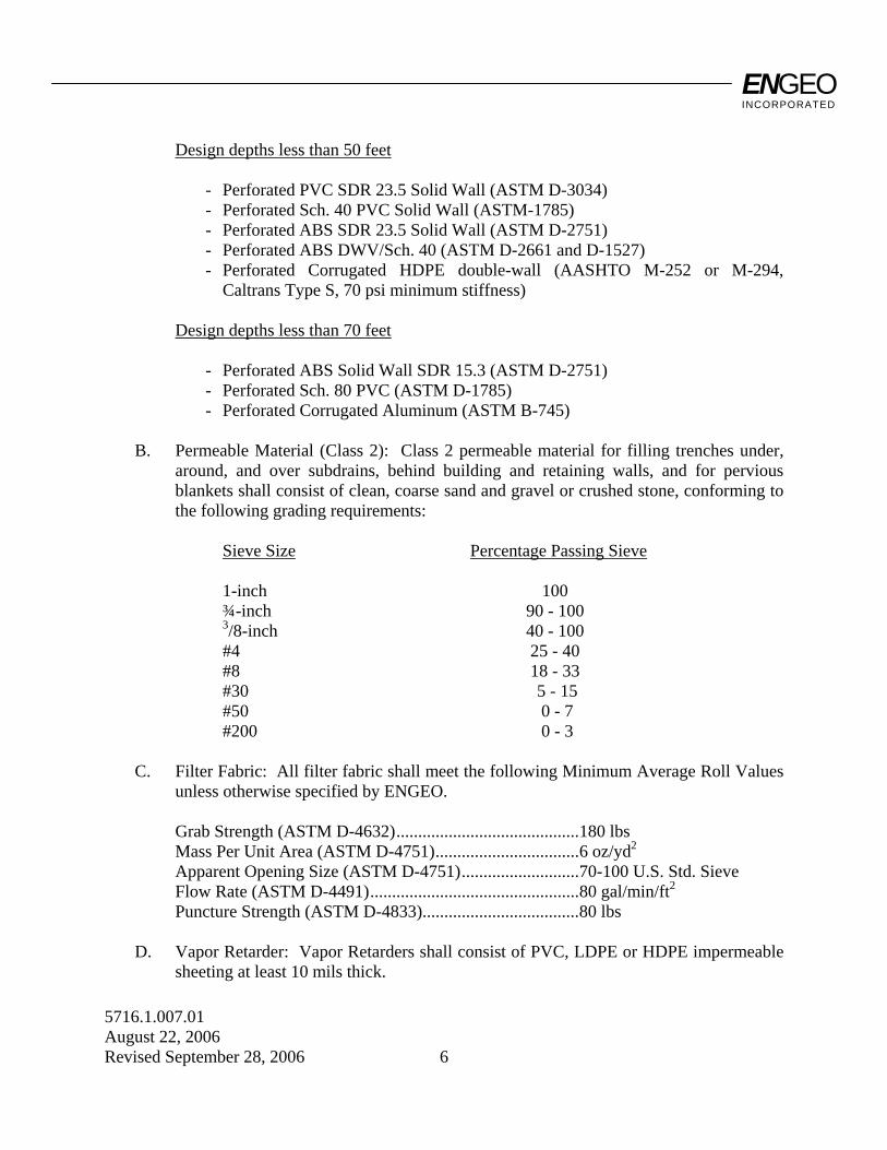
Design depths less than 50 feet - Perforated PVC SDR 23.5 Solid Wall (ASTM D-3034) - Perforated Sch. 40 PVC Solid Wall (ASTM-1785) - Perforated ABS SDR 23.5 Solid Wall (ASTM D-2751) - Perforated ABS DWV/Sch. 40 (ASTM D-2661 and D-1527) - Perforated Corrugated HDPE double-wall (AASHTO M-252 or M-294,
Caltrans Type S, 70 psi minimum stiffness) Design depths less than 70 feet - Perforated ABS Solid Wall SDR 15.3 (ASTM D-2751) - Perforated Sch. 80 PVC (ASTM D-1785) - Perforated Corrugated Aluminum (ASTM B-745) B. Permeable Material (Class 2): Class 2 permeable material for filling trenches under,
around, and over subdrains, behind building and retaining walls, and for pervious blankets shall consist of clean, coarse sand and gravel or crushed stone, conforming to the following grading requirements:
Sieve Size Percentage Passing Sieve 1-inch 100 ¾-inch 90 - 100 3/8-inch 40 - 100 #4 25 - 40 #8 18 - 33 #30 5 - 15 #50 0 - 7 #200 0 - 3 C. Filter Fabric: All filter fabric shall meet the following Minimum Average Roll Values
unless otherwise specified by ENGEO. Grab Strength (ASTM D-4632)..........................................180 lbs Mass Per Unit Area (ASTM D-4751).................................6 oz/yd2
Apparent Opening Size (ASTM D-4751)...........................70-100 U.S. Std. Sieve Flow Rate (ASTM D-4491)................................................80 gal/min/ft2
Puncture Strength (ASTM D-4833)....................................80 lbs D. Vapor Retarder: Vapor Retarders shall consist of PVC, LDPE or HDPE impermeable
sheeting at least 10 mils thick.
ENGEO INCORPORATED
5716.1.007.01 August 22, 2006 Revised September 28, 2006 7
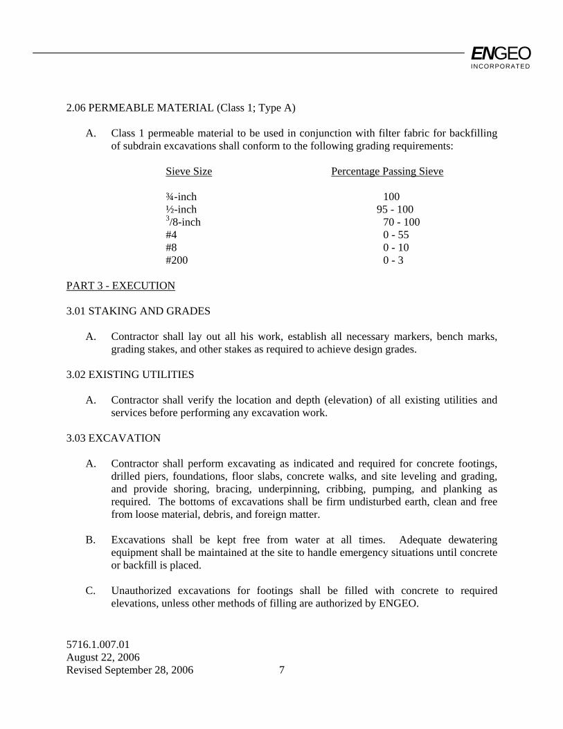
2.06 PERMEABLE MATERIAL (Class 1; Type A) A. Class 1 permeable material to be used in conjunction with filter fabric for backfilling
of subdrain excavations shall conform to the following grading requirements: Sieve Size Percentage Passing Sieve ¾-inch 100 ½-inch 95 - 100 3/8-inch 70 - 100 #4 0 - 55 #8 0 - 10 #200 0 - 3 PART 3 - EXECUTION 3.01 STAKING AND GRADES A. Contractor shall lay out all his work, establish all necessary markers, bench marks,
grading stakes, and other stakes as required to achieve design grades. 3.02 EXISTING UTILITIES A. Contractor shall verify the location and depth (elevation) of all existing utilities and
services before performing any excavation work. 3.03 EXCAVATION A. Contractor shall perform excavating as indicated and required for concrete footings,
drilled piers, foundations, floor slabs, concrete walks, and site leveling and grading, and provide shoring, bracing, underpinning, cribbing, pumping, and planking as required. The bottoms of excavations shall be firm undisturbed earth, clean and free from loose material, debris, and foreign matter.
B. Excavations shall be kept free from water at all times. Adequate dewatering
equipment shall be maintained at the site to handle emergency situations until concrete or backfill is placed.
C. Unauthorized excavations for footings shall be filled with concrete to required
elevations, unless other methods of filling are authorized by ENGEO.

ENGEO INCORPORATED
5716.1.007.01 August 22, 2006 Revised September 28, 2006 8
D. Excavated earth material which is suitable for engineered fill or backfill, as determined by ENGEO, shall be conditioned for reuse and properly stockpiled for later filling and backfilling operations as specified under Section 2.02, "Soil Materials."
E. Abandoned sewers, piping, and other utilities encountered during excavating shall be
removed and the resulting excavations shall be backfilled with engineered fill as required by ENGEO.
F. Any active utility lines encountered shall be reported immediately to the Owner's
Representative and authorities involved. The Owner and proper authorities shall be permitted free access to take the measures deemed necessary to repair, relocate, or remove the obstruction as determined by the responsible authority or Owner's Representative.
3.04 SUBGRADE PREPARATION A. All brush and other rubbish, as well as trees and root systems not marked for saving,
shall be removed from the site and legally disposed of. B. Any existing structures, foundations, underground storage tanks, or debris must be
removed from the site prior to any building, grading, or fill operations. Septic tanks, including all drain fields and other lines, if encountered, must be totally removed. The resulting depressions shall be properly prepared and filled to the satisfaction of ENGEO.
C. Vegetation and organic topsoil shall be removed from the surface upon which the fill is
to be placed and either removed and legally disposed of or stockpiled for later use in approved landscape areas. The surface shall then be scarified to a depth of at least eight inches until the surface is free from ruts, hummocks, or other uneven features which would tend to prevent uniform compaction by the equipment to be used.
D. After the foundation for the fill has been cleared and scarified, it shall be made
uniform and free from large clods. The proper moisture content must be obtained by adding water or aerating. The foundation for the fill shall be compacted at the proper moisture content to a relative compaction as specified herein.
3.05 ENGINEERED FILL A. Select Material: Fill material shall be "Select" or "Imported Material" as previously
specified.
ENGEO INCORPORATED
5716.1.007.01 August 22, 2006 Revised September 28, 2006 9
B. Placing and Compacting: Engineered fill shall be constructed by approved and accepted methods. Fill material shall be spread in uniform lifts not exceeding 8 inches in uncompacted thickness. Each layer shall be spread evenly, and thoroughly blade-mixed to obtain uniformity of material. Fill material which does not contain sufficient moisture as specified by ENGEO shall be sprinkled with water; if it contains excess moisture it shall be aerated or blended with drier material to achieve the proper water content. Select material and water shall then be thoroughly mixed before being compacted.
C. Unless otherwise specified in the Geotechnical Exploration report, each layer of spread
select material shall be compacted to at least 90 percent relative compaction at a moisture content of at least three percentage points above the optimum moisture content. Minimum compaction in all keyways shall be a minimum of 95 percent with a minimum moisture content of at least 1 percentage point above optimum.
D. Unless otherwise specified in the Geotechnical Exploration report or otherwise
required by the local authorities, the upper 6 inches of engineered fill in areas to receive pavement shall be compacted to at least 95 percent relative compaction with a minimum moisture content of at least 3 percentage points above optimum.
E. Testing and Observation of Fill: The work shall consist of field observation and testing
to determine that each layer has been compacted to the required density and that the required moisture is being obtained. Any layer or portion of a layer that does not attain the compaction required shall be reworked until the required density is obtained.
F. Compaction: Compaction shall be by sheepsfoot rollers, multiple-wheel steel or
pneumatic-tired rollers or other types of acceptable compaction equipment. Rollers shall be of such design that they will be able to compact the fill to the specified compaction. Rolling shall be accomplished while the fill material is within the specified moisture content range. Rolling of each layer must be continuous so that the required compaction may be obtained uniformly throughout each layer.
G. Fill slopes shall be constructed by overfilling the design slopes and later cutting back
the slopes to the design grades. No loose soil will be permitted on the faces of the finished slopes.
H. Strippings and topsoil shall be stockpiled as approved by Owner, then placed in
accordance with ENGEO's recommendations to a minimum thickness of 6 inches and a maximum thickness of 12 inches over exposed open space cut slopes which are 3:1 or flatter, and track walked to the satisfaction of ENGEO.
ENGEO INCORPORATED
5716.1.007.01 August 22, 2006 Revised September 28, 2006 10
I. Final Prepared Subgrade: Finish blading and smoothing shall be performed as necessary to produce the required density, with a uniform surface, smooth and true to grade.
3.06 BACKFILLING A. Backfill shall not be placed against footings, building walls, or other structures until
approved by ENGEO. B. Backfill material shall be Select Material as specified for engineered fill. C. Backfill shall be placed in 6-inch layers, leveled, rammed, and tamped in place. Each
layer shall be compacted with suitable compaction equipment to 90 percent relative compaction at a moisture content of at least 3 percent above optimum.
3.07 TRENCHING AND BACKFILLING FOR UTILITIES A. Trenching: 1. Trenching shall include the removal of material and obstructions, the installation
and removal of sheeting and bracing and the control of water as necessary to provide the required utilities and services.
2. Trenches shall be excavated to the lines, grades, and dimensions indicated on the
Drawings. Maximum allowable trench width shall be the outside diameter of the pipe plus 24 inches, inclusive of any trench bracing.
3. When the trench bottom is a soft or unstable material as determined by ENGEO, it
shall be made firm and solid by removing said unstable material to a sufficient depth and replacing it with on-site material compacted to 90 percent minimum relative compaction.
4. Where water is encountered in the trench, the contractor must provide materials
necessary to drain the water and stabilize the bed. B. Backfilling: 1. Trenches must be backfilled within 2 days of excavation to minimize desiccation. 2. Bedding material shall be sand and shall not extend more than 6 inches above any
utility lines.
ENGEO INCORPORATED
5716.1.007.01 August 22, 2006 Revised September 28, 2006 11
3. Backfill material shall be select material. 4. Trenches shall be backfilled as indicated or required and compacted with suitable
equipment to 90 percent minimum relative compaction at the required moisture content.
3.08 SUBDRAINS A. Trenches for subdrain pipe shall be excavated to a minimum width equal to the outside
diameter of the pipe plus at least 12 inches and to a depth of approximately 2 inches below the grade established for the invert of the pipe, or as indicated on the Drawings.
B. The space below the pipe invert shall be filled with a layer of Class 2 permeable
material, upon which the pipe shall be laid with perforations down. Sections shall be joined as recommended by the pipe manufacturer.
C. Rocks, bricks, broken concrete, or other hard material shall not be used to give
intermediate support to pipes. Large stones or other hard objects shall not be left in contact with the pipes.
D. Excavations for subdrains shall be filled as required to fill voids and prevent settlement
without damaging the subdrain pipe. Alternatively, excavations for subdrains may be filled with Class 1 permeable material (as defined in Section 2.06) wrapped in Filter Fabric (as defined in Section 2.05).
3.09 AGGREGATE DRAINAGE FILL A. ENGEO shall approve finished subgrades before aggregate drainage fill is installed. B. Pipes, drains, conduits, and any other mechanical or electrical installations shall be in
place before any aggregate drainage fill is placed. Backfill at walls to elevation of drainage fill shall be in place and compacted.
C. Aggregate drainage fill under slabs and concrete paving shall be the minimum uniform
thickness after compaction of dimensions indicated on Drawings. Where not indicated, minimum thickness after compaction shall be 4 inches.
D. Aggregate drainage fill shall be rolled to form a well-compacted bed. E. The finished aggregate drainage fill must be observed and approved by ENGEO before
proceeding with any subsequent construction over the compacted base or fill.
ENGEO INCORPORATED
5716.1.007.01 August 22, 2006 Revised September 28, 2006 12
3.10 SAND CUSHION A. A sand cushion shall be placed over the vapor retarder membrane under concrete slabs
on grade. Sand cushion shall be placed in uniform thickness as indicated on the Drawings. Where not indicated, the thickness shall be 2 inches.
3.11 FINISH GRADING A. All areas must be finish graded to elevations and grades indicated on the Drawings. In
areas to receive topsoil and landscape planting, finish grading shall be performed to a uniform 6 inches below the grades and elevations indicated on the Drawings, and brought to final grade with topsoil.
3.12 DISPOSAL OF WASTE MATERIALS A. Excess earth materials and debris shall be removed from the site and disposed of in a
legal manner. Location of dump site and length of haul are the Contractor's responsibility.
ENGEO INCORPORATED
5716.1.007.01 August 22, 2006 Revised September 28, 2006 13
PART II - GEOGRID SOIL REINFORCEMENT 1. DESCRIPTION: Work shall consist of furnishing geogrid soil reinforcement for use in construction of
reinforced soil slopes and retention systems. 2. GEOGRID MATERIAL: 2.1 The specific geogrid material shall be preapproved by ENGEO. 2.2 The geogrid shall be a regular network of integrally connected polymer tensile elements
with aperture geometry sufficient to permit significant mechanical interlock with the surrounding soil or rock. The geogrid structure shall be dimensionally stable and able to retain its geometry under construction stresses and shall have high resistance to damage during construction, to ultraviolet degradation, and to all forms of chemical and biological degradation encountered in the soil being reinforced.
2.3 The geogrids shall have an Allowable Strength (Ta) and Pullout Resistance, for the soil
type(s) indicated, as listed in Table I. 2.4 Certifications: The Contractor shall submit a manufacturer's certification that the
geogrids supplied meet the respective index criteria set when geogrid was approved by ENGEO, measured in full accordance with all test methods and standards specified. In case of dispute over validity of values, the Contractor will supply test data from an ENGEO-approved laboratory to support the certified values submitted.
3. CONSTRUCTION: 3.1 Delivery, Storage, and Handling: Contractor shall check the geogrid upon delivery to
ensure that the proper material has been received. During all periods of shipment and storage, the geogrid shall be protected from temperatures greater than 140 °F, mud, dirt, dust, and debris. Manufacturer's recommendations in regard to protection from direct sunlight must also be followed. At the time of installation, the geogrid will be rejected if it has defects, tears, punctures, flaws, deterioration, or damage incurred during manufacture, transportation, or storage. If approved by ENGEO, torn or punctured sections may be repaired by placing a patch over the damaged area. Any geogrid damaged during storage or installation shall be replaced by the Contractor at no additional cost to the owner.
ENGEO INCORPORATED
5716.1.007.01 August 22, 2006 Revised September 28, 2006 14
3.2 On-Site Representative: Geogrid material suppliers shall provide a qualified and
experienced representative on site at the initiation of the project, for a minimum of three days, to assist the Contractor and ENGEO personnel at the start of construction. If there is more than one slope on a project, this criterion will apply to construction of the initial slope only. The representative shall also be available on an as-needed basis, as requested by ENGEO, during construction of the remaining slope(s).
3.3 Geogrid reinforcement may be joined with mechanical connections or overlaps as
recommended and approved by the Manufacturer. Joints shall not be placed within 6 feet of the slope face, within 4 feet below top of slope, nor horizontally or vertically adjacent to another joint.
3.4 Geogrid Placement: The geogrid reinforcement shall be installed in accordance with the
manufacturer's recommendations. The geogrid reinforcement shall be placed within the layers of the compacted soil as shown on the plans or as directed.
The geogrid reinforcement shall be placed in continuous longitudinal strips in the direction
of main reinforcement. However, if the Contractor is unable to complete a required length with a single continuous length of geogrid, a joint may be made with the Manufacturer's approval. Only one joint per length of geogrid shall be allowed. This joint shall be made for the full width of the strip by using a similar material with similar strength. Joints in geogrid reinforcement shall be pulled and held taut during fill placement.
Adjacent strips, in the case of 100 percent coverage in plan view, need not be overlapped.
The minimum horizontal coverage is 50 percent, with horizontal spacings between reinforcement no greater than 40 inches. Horizontal coverage of less than 100 percent shall not be allowed unless specifically detailed in the construction drawings.
Adjacent rolls of geogrid reinforcement shall be overlapped or mechanically connected
where exposed in a wrap around face system, as applicable. The Contractor may place only that amount of geogrid reinforcement required for
immediately pending work to prevent undue damage. After a layer of geogrid reinforcement has been placed, the next succeeding layer of soil shall be placed and compacted as appropriate. After the specified soil layer has been placed, the next geogrid reinforcement layer shall be installed. The process shall be repeated for each subsequent layer of geogrid reinforcement and soil.
Geogrid reinforcement shall be placed to lay flat and pulled tight prior to backfilling.
After a layer of geogrid reinforcement has been placed, suitable means, such as pins or small piles of soil, shall be used to hold the geogrid reinforcement in position until the subsequent soil layer can be placed.
ENGEO INCORPORATED
5716.1.007.01 August 22, 2006 Revised September 28, 2006 15
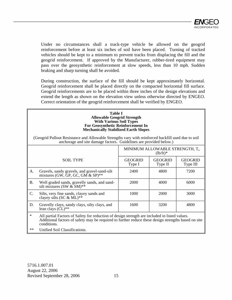
Under no circumstances shall a track-type vehicle be allowed on the geogrid
reinforcement before at least six inches of soil have been placed. Turning of tracked vehicles should be kept to a minimum to prevent tracks from displacing the fill and the geogrid reinforcement. If approved by the Manufacturer, rubber-tired equipment may pass over the geosynthetic reinforcement at slow speeds, less than 10 mph. Sudden braking and sharp turning shall be avoided.
During construction, the surface of the fill should be kept approximately horizontal.
Geogrid reinforcement shall be placed directly on the compacted horizontal fill surface. Geogrid reinforcements are to be placed within three inches of the design elevations and extend the length as shown on the elevation view unless otherwise directed by ENGEO. Correct orientation of the geogrid reinforcement shall be verified by ENGEO.
Table I
Allowable Geogrid Strength With Various Soil Types
For Geosynthetic Reinforcement In Mechanically Stabilized Earth Slopes
(Geogrid Pullout Resistance and Allowable Strengths vary with reinforced backfill used due to soil
anchorage and site damage factors. Guidelines are provided below.) MINIMUM ALLOWABLE STRENGTH, Ta
(lb/ft)*
SOIL TYPE GEOGRID Type I
GEOGRID Type II
GEOGRID Type III
A. Gravels, sandy gravels, and gravel-sand-silt mixtures (GW, GP, GC, GM & SP)**
2400 4800 7200
B. Well graded sands, gravelly sands, and sand-silt mixtures (SW & SM)**
2000 4000 6000
C. Silts, very fine sands, clayey sands and clayey silts (SC & ML)**
1000 2000 3000
D. Gravelly clays, sandy clays, silty clays, and lean clays (CL)**
1600 3200 4800
* All partial Factors of Safety for reduction of design strength are included in listed values. Additional factors of safety may be required to further reduce these design strengths based on site conditions.
** Unified Soil Classifications.
ENGEO INCORPORATED
5716.1.007.01 August 22, 2006 Revised September 28, 2006 16
PART III - GEOTEXTILE SOIL REINFORCEMENT 1. DESCRIPTION: Work shall consist of furnishing geotextile soil reinforcement for use in construction of
reinforced soil slopes. 2. GEOTEXTILE MATERIAL: 2.1 The specific geotextile material and supplier shall be preapproved by ENGEO. 2.2 The geotextile shall have a high tensile modulus and shall have high resistance to damage
during construction, to ultraviolet degradation, and to all forms of chemical and biological degradation encountered in the soil being reinforced.
2.3 The geotextiles shall have an Allowable Strength (Ta) and Pullout Resistance, for the soil
type(s) indicated as listed in Table II. 2.4 Certification: The Contractor shall submit a manufacturer's certification that the
geotextiles supplied meet the respective index criteria set when geotextile was approved by ENGEO, measured in full accordance with all test methods and standards specified. In case of dispute over validity of values, the Contractor will supply the data from an ENGEO-approved laboratory to support the certified values submitted.
3. CONSTRUCTION: 3.1 Delivery, Storage and Handling: Contractor shall check the geotextile upon delivery to
ensure that the proper material has been received. During all periods of shipment and storage, the geotextile shall be protected from temperatures greater than 140 °F, mud, dirt, dust, and debris. Manufacturer's recommendations in regard to protection from direct sunlight must also be followed. At the time of installation, the geotextile will be rejected if it has defects, tears, punctures, flaws, deterioration, or damage incurred during manufacture, transportation, or storage. If approved by ENGEO, torn or punctured sections may be repaired by placing a patch over the damaged area. Any geotextile damaged during storage or installation shall be replaced by the Contractor at no additional cost to the owner.
ENGEO INCORPORATED
5716.1.007.01 August 22, 2006 Revised September 28, 2006 17
3.2 On-Site Representative: Geotextile material suppliers shall provide a qualified and experienced representative on site at the initiation of the project, for a minimum of three days, to assist the Contractor and ENGEO personnel at the start of construction. If there is more than one slope on a project, this criterion will apply to construction of the initial slope only. The representative shall also be available on an as-needed basis, as requested by ENGEO, during construction of the remaining slope(s).
3.3 Geotextile Placement: The geotextile reinforcement shall be installed in accordance with
the manufacturer's recommendations. The geotextile reinforcement shall be placed within the layers of the compacted soil as shown on the plans or as directed.
The geotextile reinforcement shall be placed in continuous longitudinal strips in the
direction of main reinforcement. Joints shall not be used with geotextiles. Adjacent strips, in the case of 100 percent coverage in plan view, need not be overlapped.
The minimum horizontal coverage is 50 percent, with horizontal spacings between reinforcement no greater than 40 inches. Horizontal coverage of less than 100 percent shall not be allowed unless specifically detailed in the construction drawings.
Adjacent rolls of geotextile reinforcement shall be overlapped or mechanically connected
where exposed in a wrap around face system, as applicable. The Contractor may place only that amount of geotextile reinforcement required for
immediately pending work to prevent undue damage. After a layer of geotextile reinforcement has been placed, the succeeding layer of soil shall be placed and compacted as appropriate. After the specified soil layer has been placed, the next geotextile reinforcement layer shall be installed. The process shall be repeated for each subsequent layer of geotextile reinforcement and soil.
Geosynthetic reinforcement shall be placed to lay flat and be pulled tight prior to
backfilling. After a layer of geotextile reinforcement has been placed, suitable means, such as pins or small piles of soil, shall be used to hold the geotextile reinforcement in position until the subsequent soil layer can be placed.
Under no circumstances shall a track-type vehicle be allowed on the geotextile
reinforcement before at least six inches of soil has been placed. Turning of tracked vehicles should be kept to a minimum to prevent tracks from displacing the fill and the geotextile reinforcement. If approved by the Manufacturer, rubber-tired equipment may pass over the geotextile reinforcement as slow speeds, less than 10 mph. Sudden braking and sharp turning shall be avoided.
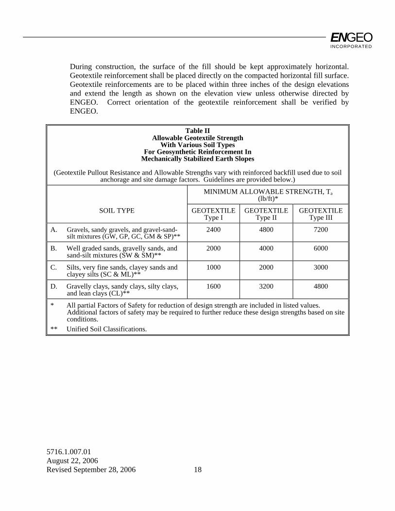
ENGEO INCORPORATED
5716.1.007.01 August 22, 2006 Revised September 28, 2006 18
During construction, the surface of the fill should be kept approximately horizontal. Geotextile reinforcement shall be placed directly on the compacted horizontal fill surface. Geotextile reinforcements are to be placed within three inches of the design elevations and extend the length as shown on the elevation view unless otherwise directed by ENGEO. Correct orientation of the geotextile reinforcement shall be verified by ENGEO.
Table II
Allowable Geotextile Strength With Various Soil Types
For Geosynthetic Reinforcement In Mechanically Stabilized Earth Slopes
(Geotextile Pullout Resistance and Allowable Strengths vary with reinforced backfill used due to soil
anchorage and site damage factors. Guidelines are provided below.) MINIMUM ALLOWABLE STRENGTH, Ta
(lb/ft)*
SOIL TYPE GEOTEXTILE Type I
GEOTEXTILE Type II
GEOTEXTILE Type III
A. Gravels, sandy gravels, and gravel-sand-silt mixtures (GW, GP, GC, GM & SP)**
2400 4800 7200
B. Well graded sands, gravelly sands, and sand-silt mixtures (SW & SM)**
2000 4000 6000
C. Silts, very fine sands, clayey sands and clayey silts (SC & ML)**
1000 2000 3000
D. Gravelly clays, sandy clays, silty clays, and lean clays (CL)**
1600 3200 4800
* All partial Factors of Safety for reduction of design strength are included in listed values. Additional factors of safety may be required to further reduce these design strengths based on site conditions.
** Unified Soil Classifications.

ENGEO INCORPORATED
5716.1.007.01 August 22, 2006 Revised September 28, 2006 19
PART IV - EROSION CONTROL MAT OR BLANKET 1. DESCRIPTION: Work shall consist of furnishing and placing a synthetic erosion control mat and/or
degradable erosion control blanket for slope face protection and lining of runoff channels. 2. EROSION CONTROL MATERIALS: 2.1 The specific erosion control material and supplier shall be pre-approved by ENGEO. 2.2 Certification: The Contractor shall submit a manufacturer's certification that the erosion
mat/blanket supplied meets the criteria specified when the material was approved by ENGEO. The manufacturer's certification shall include a submittal package of documented test results that confirm the property values. In case of a dispute over validity of values, the Contractor will supply property test data from an ENGEO-approved laboratory, to support the certified values submitted. Minimum average roll values, per ASTM D 4759, shall be used for conformance determinations.
3. CONSTRUCTION: 3.1 Delivery, Storage, and Handling: Contractor shall check the erosion control material
upon delivery to ensure that the proper material has been received. During all periods of shipment and storage, the erosion mat shall be protected from temperatures greater than 140 °F, mud, dirt, and debris. Manufacturer's recommendations in regard to protection from direct sunlight must also be followed. At the time of installation, the erosion mat/blanket shall be rejected if it has defects, tears, punctures, flaws, deterioration, or damage incurred during manufacture, transportation, or storage. If approved by ENGEO, torn or punctured sections may be removed by cutting OUT a section of the mat. The remaining ends should be overlapped and secured with ground anchors. Any erosion mat/blanket damaged during storage or installation shall be replaced by the Contractor at no additional cost to the Owner.
3.2 On-Site Representative: Erosion control material suppliers shall provide a qualified and
experienced representative on site, for a minimum of one day, to assist the Contractor and ENGEO personnel at the start of construction. If there is more than one slope on a project, this criteria will apply to construction of the initial slope only. The representative shall be available on an as-needed basis, as requested by ENGEO, during construction of the remaining slope(s).
ENGEO INCORPORATED
5716.1.007.01 August 22, 2006 Revised September 28, 2006 20
3.3 Placement: The erosion control material shall be placed and anchored on a smooth
graded, firm surface approved by the Engineer. Anchoring terminal ends of the erosion control material shall be accomplished through use of key trenches. The material in the trenches shall be anchored to the soil on maximum 1½ foot centers. Topsoil, if required by construction drawings, placed over final grade prior to installation of the erosion control material shall be limited to a depth not exceeding 3 inches.
3.4 Erosion control material shall be anchored, overlapped, and otherwise constructed to
ensure performance until vegetation is well established. Anchors shall be as designated on the construction drawings, with a minimum of 12 inches length, and shall be spaced as designated on the construction drawings, with a maximum spacing of 4 feet.
3.5 Soil Filling: If noted on the construction drawings, the erosion control mat shall be filled
with a fine grained topsoil, as recommended by the manufacturer. Soil shall be lightly raked or brushed on/into the mat to fill the mat voids or to a maximum depth of 1 inch.
ENGEO INCORPORATED
5716.1.007.01 August 22, 2006 Revised September 28, 2006 21
PART V - GEOSYNTHETIC DRAINAGE COMPOSITE 1. DESCRIPTION: Work shall consist of furnishing and placing a geosynthetic drainage system as a subsurface
drainage medium for reinforced soil slopes. 2. DRAINAGE COMPOSITE MATERIALS: 2.1 The specific drainage composite material and supplier shall be preapproved by ENGEO. 2.2 The drain shall be of composite construction consisting of a supporting structure or
drainage core material surrounded by a geotextile. The geotextile shall encapsulate the drainage core and prevent random soil intrusion into the drainage structure. The drainage core material shall consist of a three dimensional polymeric material with a structure that permits flow along the core laterally. The core structure shall also be constructed to permit flow regardless of the water inlet surface. The drainage core shall provide support to the geotextile. The fabric shall meet the minimum property requirements for filter fabric listed in Section 2.05C of the Guide Earthwork Specifications.
2.3 A geotextile flap shall be provided along all drainage core edges. This flap shall be of
sufficient width for sealing the geotextile to the adjacent drainage structure edge to prevent soil intrusion into the structure during and after installation. The geotextile shall cover the full length of the core.
2.4 The geocomposite core shall be furnished with an approved method of constructing and
connecting with outlet pipes or weepholes as shown on the plans. Any fittings shall allow entry of water from the core but prevent intrusion of backfill material into the core material.
2.5 Certification and Acceptance: The Contractor shall submit a manufacturer's certification
that the geosynthetic drainage composite meets the design properties and respective index criteria measured in full accordance with all test methods and standards specified. The manufacturer's certification shall include a submittal package of documented test results that confirm the design values. In case of dispute over validity of design values, the Contractor will supply design property test data from an ENGEO-approved laboratory, to support the certified values submitted. Minimum average roll values, per ASTM D 4759, shall be used for determining conformance.
ENGEO INCORPORATED
5716.1.007.01 August 22, 2006 Revised September 28, 2006 22
3. CONSTRUCTION: 3.1 Delivery, Storage, and Handling: Contractor shall check the geosynthetic drainage
composite upon delivery to ensure that the proper material has been received. During all periods of shipment and storage, the geosynthetic drainage composite shall be protected from temperatures greater than 140 °F, mud, dirt, and debris. Manufacturer's recommendations in regards to protection from direct sunlight must also be followed. At the time of installation, the geosynthetic drainage composite shall be rejected if it has defects, tears, punctures, flaws, deterioration, or damage incurred during manufacture, transportation, or storage. If approved by ENGEO, torn or punctured sections may be removed or repaired. Any geosynthetic drainage composite damaged during storage or installation shall be replaced by the Contractor at no additional cost to the Owner.
3.2 On-Site Representative: Geosynthetic drainage composite material suppliers shall
provide a qualified and experienced representative on site, for a minimum of one half day, to assist the Contractor and ENGEO personnel at the start of construction with directions on the use of drainage composite. If there is more than one application on a project, this criterion will apply to construction of the initial application only. The representative shall also be available on an as-needed basis, as requested by ENGEO, during construction of the remaining applications.
3.3 Placement: The soil surface against which the geosynthetic drainage composite is to be
placed shall be free of debris and inordinate irregularities that will prevent intimate contact between the soil surface and the drain.
3.4 Seams: Edge seams shall be formed by utilizing the flap of the geotextile extending from
the geocomposite's edge and lapping over the top of the fabric of the adjacent course. The fabric flap shall be securely fastened to the adjacent fabric by means of plastic tape or non-water-soluble construction adhesive, as recommended by the supplier. Where vertical splices are necessary at the end of a geocomposite roll or panel, an 8-inch-wide continuous strip of geotextile may be placed, centering over the seam and continuously fastened on both sides with plastic tape or non-water-soluble construction adhesive. As an alternative, rolls of geocomposite drain material may be joined together by turning back the fabric at the roll edges and interlocking the cuspidations approximately 2 inches. For overlapping in this manner, the fabric shall be lapped and tightly taped beyond the seam with tape or adhesive. Interlocking of the core shall always be made with the upstream edge on top in the direction of water flow. To prevent soil intrusion, all exposed edges of the geocomposite drainage core edge must be covered. Alternatively, a 12-inch-wide strip of fabric may be utilized in the same manner, fastening it to the exposed fabric 8 inches in from the edge and folding the remaining flap over the core edge.
ENGEO INCORPORATED
5716.1.007.01 August 22, 2006 Revised September 28, 2006 23
3.5 Soil Fill Placement: Structural backfill shall be placed immediately over the geocomposite drain. Care shall be taken during the backfill operation not to damage the geotextile surface of the drain. Care shall also be taken to avoid excessive settlement of the backfill material. The geocomposite drain, once installed, shall not be exposed for more than seven days prior to backfilling.