Embed Size (px)
Citation preview

GEOTECHNICAL EVALUATION
WELBY ROAD REALIGNMENT
NORTH OF 88TH
AVENUE
THORNTON, COLORADO
CITY OF THORNTON PROJECT NO. 12-703-A
PREPARED FOR:
ICON Engineering, Inc.
8100 Akron Street, Suite 300
Englewood, Colorado 80112
PREPARED BY:
Ninyo & Moore
Geotechnical and Environmental Sciences Consultants
6001 S. Willow Drive, Suite 195
Greenwood Village, Colorado 80111
January 26, 2015
Project No. 500907001

January 26, 2015
Project No. 500907001
Mr. Matthew J. Ursetta, P.E.
ICON Engineering
8100 Akron Street, Suite 300
Englewood, Colorado 80112
Subject: Geotechnical Evaluation
Welby Road Realignment North of 88th
Avenue
Thornton, Colorado
City of Thornton Project No. 12-703-A
Dear Mr. Ursetta:
In accordance with our proposal dated November 13, 2014 and your authorization, Ninyo &
Moore has performed a geotechnical evaluation for the proposed realignment of Welby Road
north of 88th
Avenue in Thornton, Colorado. The attached report presents our methodology,
findings, and recommendations regarding the geotechnical aspects of the project.
We appreciate the opportunity to be of service to you during this phase of the project.
Sincerely,
NINYO & MOORE
JMJ/SS/ceb
Distribution: (1) Addressee (via e-mail)
Jeffrey M. Jones, PE
Senior Project Engineer
Serkan Sengul, PE
Principal Engineer
1.26.151.26.15

Welby Road Realignment – North of 88th
Avenue January 26, 2015
Thornton, Colorado Project No. 500889001
500907001 R.doc i
TABLE OF CONTENTS
Page
1. INTRODUCTION ....................................................................................................................1
2. SCOPE OF SERVICES ............................................................................................................1
3. ALIGNMENT DESCRIPTION AND PROPOSED CONSTRUCTION .................................2
4. FIELD EXPLORATION AND LABORATORY TESTING ....................................................3
5. GEOLOGY AND SUBSURFACE CONDITIONS .................................................................3
5.1. Geologic Setting ...........................................................................................................4 5.2. Subsurface Conditions ..................................................................................................4
5.2.1. Fill .......................................................................................................................4
5.2.2. Alluvium .............................................................................................................5 5.3. Groundwater .................................................................................................................5
6. GEOLOGIC HAZARDS ..........................................................................................................5
6.1. Expansive Soils .............................................................................................................6 6.2. Collapsible Soils/Consolidation Settlement .................................................................6
7. CONCLUSIONS ......................................................................................................................7
8. RECOMMENDATIONS ..........................................................................................................8 8.1. Earthwork .....................................................................................................................8
8.1.1. Clearing and Grubbing ........................................................................................8
8.1.2. Excavations .........................................................................................................9
8.1.3. Treatment of Alignment Subgrade Soils .............................................................9 8.1.4. Alignment Grading............................................................................................11
8.1.5. Imported Alignment Grade Raise Fill Material ................................................12 8.1.6. Fill Placement and Compaction ........................................................................12 8.1.7. Utility Installation .............................................................................................13
8.1.8. Temporary Cut Slopes.......................................................................................13 8.2. Pavements ...................................................................................................................16
8.2.1. Pavement Section Design ..................................................................................16 8.2.2. Pavement Materials ...........................................................................................17 8.2.3. Roadway Subgrade Preparation ........................................................................17
8.3. Corrosivity ..................................................................................................................19
8.4. Concrete ......................................................................................................................20 8.5. Scaling ........................................................................................................................20 8.6. Construction in Cold or Wet Weather ........................................................................21
8.7. Construction Plan Review and Pre-Construction Conference ....................................22 8.8. Construction Observation ...........................................................................................22
9. LIMITATIONS .......................................................................................................................23
10. REFERENCES .......................................................................................................................25

Welby Road Realignment – North of 88th
Avenue January 26, 2015
Thornton, Colorado Project No. 500889001
500907001 R.doc ii
Figures
Figure 1 – Site Location Map
Figure 2 – Boring Location Map
Appendices
Appendix A – Boring Logs
Appendix B – Laboratory Testing
Appendix C - Flexible Pavement Calculations

Welby Road Realignment – North of 88th
Avenue January 26, 2015
Thornton, Colorado Project No. 500889001
500907001 R.doc 1
1. INTRODUCTION
In accordance with our proposal dated November 13, 2014 and your authorization, we have
performed a geotechnical evaluation for the proposed realignment of Welby Road north of 88th
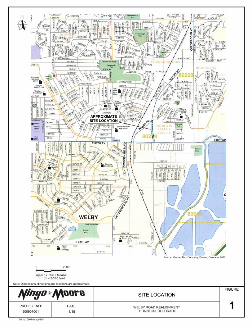
Avenue, in Thornton, Colorado. The approximate location of the site is depicted on Figure 1.
The purpose of our study was to evaluate the subsurface conditions and to provide design and
construction recommendations regarding geotechnical aspects of the proposed project. This
report presents the findings of our subsurface exploration, results of our laboratory testing,
conclusions regarding the subsurface conditions at the site, and geotechnical recommendations
for design and construction of this project.
2. SCOPE OF SERVICES
The scope of our services for the project generally included:
Reviewing readily available aerial photographs and published geologic literature, including
maps and reports pertaining to the project site and vicinity.
Notifying Utility Notification Center of Colorado (UNCC) of the boring locations prior to
drilling.
Drilling, logging, and sampling four small-diameter exploratory borings along the proposed
roadway realignment. The borings were drilled to depths of approximately 8.5 feet below the
ground surface (bgs). The boring logs are presented in Appendix A.
Performing laboratory tests of selected samples obtained from the borings to evaluate in-situ
moisture content and dry density, No. 200 sieve analyses, gradation analyses, Atterberg
limits, swell/consolidation potential, R-value, and corrosivity characteristics (including pH,
minimum electrical resistivity, water-soluble sulfates and chlorides). The results of the in-situ
moisture content and dry density testing are presented on the boring logs in Appendix A. The
remainder of the laboratory test results is presented in Appendix B.
Compiling and analyzing of the data obtained. Pavement section thickness calculations are
presented in Appendix C.
Preparing this report presenting our findings, conclusions, and geotechnical
recommendations regarding design and construction of the project.

Welby Road Realignment – North of 88th
Avenue January 26, 2015
Thornton, Colorado Project No. 500889001
500907001 R.doc 2
3. ALIGNMENT DESCRIPTION AND PROPOSED CONSTRUCTION
The proposed Welby Road realignment is planned to diverge from the existing alignment
immediately south of Beachwood Drive in a general north-south direction and cross an area that
has been previously graded before entering agricultural land to its termination at 88th
Avenue.
The realignment topography is relatively flat with grades of less than 1 percent.
The proposed roadway alignment, extending northerly from 88th Avenue to the proposed RTD
Access intersection, will be located across a farmed land. Based on our preliminary review of the
available historic aerial photographs, it that the portion of the alignment located north of the RTD
Access intersection and south of Welby Road will cross a property that used to be occupied by
single-family residences. The aerial photography depicts the placement of a significant amount
of fill material across portion of the alignment north of the RTD Access intersection. The fill was
light brown in color and was placed as a series of end dump piles during the spring to summer
months of 2007. By June of 2010, the fill was spread across the property and the single-family
residences that occupied the land were demolished. The area was re-graded and re-seeded
between 2013 and 2014. At this time, we have not been provided documentation that suggests
the fill was placed in a controlled manner.
The realignment project consists of the design and construction of a new 1,440 lineal-foot road.
In addition, the project will include a new traffic signal at the intersection of the realigned Welby
Road and 88th
Avenue. Preliminary design information indicates the realignment segment
between 88th
and 89th
Avenue will consist of a four lane divided roadway with a center median.
The realignment segment north of 89th
Avenue will consist of three lanes. Both segments will
include bike lanes. Curb and gutter will be installed along the east side of the realignment while
the west side will include a gravel shoulder. A culvert is planned for the Lower Creek Creek
Ditch crossing at the north end of the alignment. We understand the culvert may include cast-in-
place concrete headwalls and wing walls. The proposed roadway realignment is depicted on
Figure 2.

Welby Road Realignment – North of 88th
Avenue January 26, 2015
Thornton, Colorado Project No. 500889001
500907001 R.doc 3
We understand that the realignment will be designed and constructed in general accordance with
the City of Thornton Standards and Specifications and that Welby Road will be designed as a
Major Collector.
4. FIELD EXPLORATION AND LABORATORY TESTING
On December 29, 2014, Ninyo & Moore conducted a subsurface exploration along the
realignment limits in order to evaluate the existing subsurface conditions and to collect soil
samples for visual observation and laboratory testing.
Our evaluation consisted of drilling, logging, and sampling four exploratory borings along the
subject roadway alignment. The borings were advanced using a CME-55 truck-mounted drill rig
equipped with solid-stem continuous-flight augers. The borings were drilled to depths of
approximately 8.5 feet bgs. Bulk and relatively undisturbed soil samples were collected at
selected intervals. Detailed descriptions of the soils and groundwater encountered in our borings
are presented on the boring logs in Appendix A. The approximate locations of the borings are
depicted on Figure 2.
Soil samples collected during our subsurface exploration were transported to the Ninyo & Moore
laboratory for geotechnical laboratory analyses. Selected samples were analyzed to evaluate
engineering properties including in-situ moisture content and dry density, Atterberg limits, No.
200 sieve analyses, gradation analyses, swell/consolidation potential, R-Value, and corrosivity
characteristics (including pH, minimum electrical resistivity, soluble sulfates, and chlorides). The
results of the in-situ moisture content and dry density testing are presented on the boring logs in
Appendix A. A description of each laboratory test method and the remainder of the test results
are presented in Appendix B.
5. GEOLOGY AND SUBSURFACE CONDITIONS
The geology and subsurface conditions at the site are described in the following sections.
Welby Road Realignment – North of 88th
Avenue January 26, 2015
Thornton, Colorado Project No. 500889001
500907001 R.doc 4
5.1. Geologic Setting
The alignment is located approximately 17 miles east of the Rocky Mountain Front Range,
within the Colorado Piedmont section of the Great Plains Physiographic Province. The
Laramide Orogeny uplifted the Rocky Mountains during the late Cretaceous and early
Tertiary Periods. Subsequent erosion deposited sediments east of the Rocky Mountains,
including the Denver Formation in the area. As a result of regional uplift approximately 5 to
10 million years ago, streams such as the South Platte River downcut and excavated into the
Great Plains forming the Colorado Piedmont section (Trimble, 1980). The surficial geology
of the site vicinity is mapped by Trimble and Machette (1979) as loess soil (wind-blown or
eolian silt generally derived from upwind glacial deposits). Based on the sandy clay
composition of the material encountered during our subsurface exploration and the
proximity to the South Platte River, we are referring to the material as alluvium. The Denver
Formation is mapped underlying the proposed roadway alignments at depth.
5.2. Subsurface Conditions
Our understanding of the subsurface conditions at the project site is based on our field
exploration and laboratory testing, review of published geologic maps, historic topographic
maps, historic aerial photographs, and our experience with the general geology of the area.
The following sections provide a generalized description of the subsurface materials
encountered. Descriptions that are more detailed are presented on the boring logs in
Appendix A.
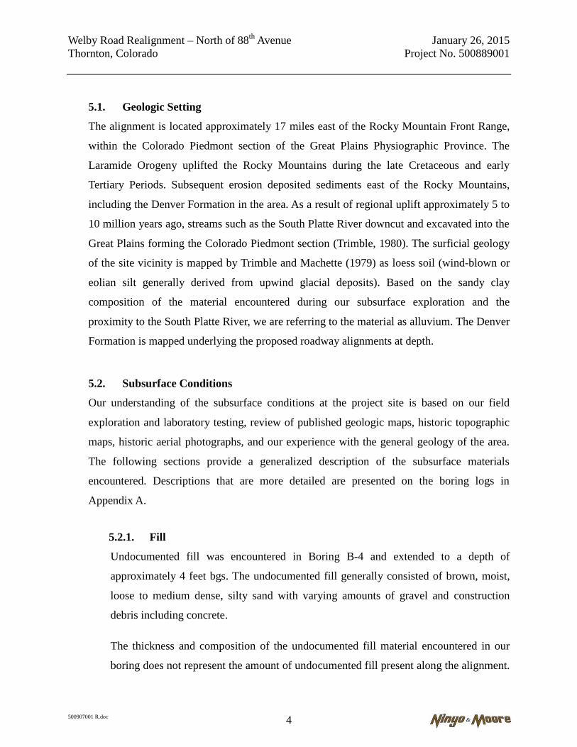
5.2.1. Fill
Undocumented fill was encountered in Boring B-4 and extended to a depth of
approximately 4 feet bgs. The undocumented fill generally consisted of brown, moist,
loose to medium dense, silty sand with varying amounts of gravel and construction
debris including concrete.
The thickness and composition of the undocumented fill material encountered in our
boring does not represent the amount of undocumented fill present along the alignment.

Welby Road Realignment – North of 88th
Avenue January 26, 2015
Thornton, Colorado Project No. 500889001
500907001 R.doc 5
The design and construction team should assume additional uncontrolled fill materials
are present along the northern end of the alignment. The fill material encountered is
considered undocumented and is not suitable to support the loads generated during the
placement of grade-raise fill or roadway and associated improvements.
5.2.2. Alluvium
Alluvium was generally encountered at the surface or underlying fill material and
extended to the boring termination depths of approximately 8.5 feet bgs.
Alluvium encountered generally consisted of brown to light brown, moist, stiff to very
stiff, lean to fat clay with varying amounts of sand. In Borings B-1 and B-4 granular
alluvium was encountered at a depth of approximately 7 feet bgs consisting of light
brown to brown, moist, medium dense, clayey sand.
Based on the results of our subsurface exploration and laboratory testing, the alluvium
exhibited low to high plasticity. Selected samples had in-place moisture contents
between 16.3 and 27.1 percent and dry densities between 96.1 and 106.9 pcf.
5.3. Groundwater
Groundwater was not encountered during drilling to the total depth explored of
approximately 8.5 feet bgs. Groundwater levels will fluctuate due to seasonal variations,
irrigation, groundwater withdrawal or injection, and other factors. In general, groundwater is
not expected to be a constraint to construction of the project.
6. GEOLOGIC HAZARDS
The following sections describe potential geologic hazards at the site, including expansive soils,
and collapsible soils.

Welby Road Realignment – North of 88th
Avenue January 26, 2015
Thornton, Colorado Project No. 500889001
500907001 R.doc 6
6.1. Expansive Soils
One of the more significant geologic hazards in the Front Range area is the presence of
swelling clays in bedrock or surficial deposits. Moisture changes to bedrock or surficial
deposits containing swelling clays can result in volumetric expansion and collapse of those
units. Changes in soil moisture can result from precipitation, irrigation, pipeline leakage,
surface drainage, perched groundwater, drought, or other factors. Volumetric change of
expansive soil may cause excessive cracking and heaving of pavements supported on these
materials.
A review of a Colorado Geological Survey map delineating areas based on their relative
potential for swelling in the City of Thornton area by Hart (1974) indicates that the soil and
bedrock materials in the alignment vicinity typically exhibit low to moderate swell potential.
Selected samples tested exhibited percent swell values of 1.7 percent to 6.5 percent when
wetted against a surcharge pressure of 200 pounds per square foot (psf). The plasticity index
of the shallow subgrade soils generally varied between 28 and 33. Based on the plasticity
index, percent swell, and swell pressure results, the probable swell damage risk of the
subgrade soils are considered low to high on a scale of none, low, medium, high, and very
high.
6.2. Collapsible Soils/Consolidation Settlement
Compressible soils are generally comprised of soils that undergo consolidation when
exposed to new loadings, such as fill or foundation loads. Soil collapse (or hydro-collapse)
is a phenomenon where soils undergo a significant decrease in volume upon and increase in
moisture content, with or without an increase in external loads. Buildings, structures, and
other improvements may be subject to excessive settlement-related distress when
compressible soils or collapsible soils are present. Based on the subsurface exploration and
information obtained from our background review, the site is underlain by fill material and
alluvium that extends to depths ranging between approximately 8.5 feet bgs or more.

Welby Road Realignment – North of 88th
Avenue January 26, 2015
Thornton, Colorado Project No. 500889001
500907001 R.doc 7
Considering the relatively minor (less than 4 feet of material cuts and fills) alignment
grading that will be needed to achieve the finished roadway grades, combined with the
relatively light loads that the roadway will impose onto the subgrade, consolidation of the
site soils is not a design concern for the proposed roadway. Select samples tested did not
exhibit significant consolidation when wetted against a surcharge pressure of 200 psf.
7. CONCLUSIONS
Based on the results of our background review, subsurface evaluation, laboratory testing, and
data analysis, it is our opinion that proposed public roadway realignment is feasible from a
geotechnical standpoint provided the recommendations presented herein are implemented and
appropriate construction practices are followed. Geotechnical design and construction
considerations for the proposed project include the following:
The proposed Welby Road realignment is underlain by 4 or more feet of fill at the northern
end of the alignment. The fill material encountered consisted of brown, moist, loose to
medium dense, silty sandy with varying amounts of gravel as well as construction debris
including concrete chunks. The fill material encountered is considered undocumented and is
not suitable to support the loads generated during the placement of grade-raise fill or
roadway and associated improvements. Undocumented fill will need to be removed, moisture
conditioned, and recompacted prior to roadway construction to reduce probable settlement
risk. As the fill material encountered in Boring B-4 contained various amounts of
construction debris, some of the excavated fill material may not be suitable for re-use. The
geotechnical engineer should be retained to conduct additional observations during grading
to further evaluate fill material re-use suitability.
Alluvium was encountered at the surface or below the fill material in each of our borings and
extended to the boring termination depths of approximately 8.5 feet bgs. Alluvium
encountered generally consisted of brown to light brown, moist, stiff to very stiff, lean to fat
clay with varying amounts of sand. In Borings B-1 and B-4 granular alluvium was
encountered at a depth of approximately 7 feet bgs consisting of light brown to brown, moist,
medium dense, clayey sand. The alluvium has low to high swell potential and low
consolidation potential. A portion of the alluvium will need to be moisture conditioned and
recompacted prior to roadway construction to reduce probable swell damage risk.
Groundwater was not encountered to the total depth explored of approximately 8.5 feet bgs.
Groundwater levels will fluctuate due to seasonal variations, irrigation, groundwater
withdrawal or injection, and other factors. In general, groundwater is not expected to be a
constraint to construction of the project.

Welby Road Realignment – North of 88th
Avenue January 26, 2015
Thornton, Colorado Project No. 500889001
500907001 R.doc 8
The on-site soils should generally be excavatable to the anticipated removal depths with
heavy-duty earthmoving or excavating equipment in good operating condition.
Site soils generated from on-site excavation activities consisting of alluvium that are free of
deleterious materials, and do not contain particles larger than 3 inches in diameter, can
generally be used as engineered fill during utility installation and alignment grading. The
undocumented fill material may contain deleterious material and should be further evaluated
prior to use as engineered fill. Based on our understanding of the subsurface conditions,
addition of moisture, drying, blending with drier material, may be needed to raise or lower
the moisture contents of the excavated site soils prior to placement.
Corrosivity test results indicate that subgrade soils at the site are generally considered severly
corrosive to ferrous metals.
The sulfate content of the tested soils presents a negligible risk of sulfate attack to concrete.
Notwithstanding the sulfate test results, we recommend the use of Type II cement for
construction of concrete structures at this site.
8. RECOMMENDATIONS
Based on our understanding of the project, the following sections present our geotechnical
recommendations for design and construction of the proposed commercial development. These
recommendations were prepared based on the assumption that minor cuts and fills of 5 feet or
less will be needed to achieve finish grades.
8.1. Earthwork
Public roadway and utility improvements should be constructed in accordance with the City
of Thornton Standards and Specifications for the Design and Construction of Public and
Private Improvements, latest edition (City of Thornton Specifications). The following
sections provide our earthwork recommendations for this project. In case of conflict, City of
Thornton Specifications will govern.
8.1.1. Clearing and Grubbing
Prior to grading, the ground surface along the proposed roadway alignments should be
cleared of any surface obstructions, debris, topsoil, organics (including vegetation), and
other deleterious material. Abandoned utilities, septic fields, and relic foundations may

Welby Road Realignment – North of 88th
Avenue January 26, 2015
Thornton, Colorado Project No. 500889001
500907001 R.doc 9
be present along the northern portion of the alignment that was previously occupied by
single-family residences.
Materials generated from clearing operations should be removed from the site and
disposed of at a legal dumpsite. Obstructions that extend below finish grade, if present,
should be removed and the resulting holes filled with compacted soil or cement slurry,
in accordance with the recommendations of the geotechnical consultant.
8.1.2. Excavations
Our evaluation of the excavation characteristics of the on-site materials is based on the
results of the subsurface exploration, our site observations, and our experience with
similar materials. The on-site surface and near surface soils (fill and alluvium) may
generally be excavated with heavy-duty earthmoving or excavation equipment in good
operating condition.
Equipment and procedures that do not cause significant disturbance to the excavation
bottoms should be used. Excavators and backhoes with buckets having large claws to
loosen the soil should be avoided when excavating the bottom 6 to 12 inches of
excavations as such equipment may disturb the excavation bases.
The contractor should provide safely sloped excavations or an adequately constructed
and braced shoring system, in compliance with Occupational Safety and Health
Administration (OSHA) guidelines, for employees working in an excavation that may
expose employees to the danger of moving ground. If material is stored or equipment is
operated near an excavation, stronger shoring should be used to resist the extra pressure
due to superimposed loads.
8.1.3. Treatment of Alignment Subgrade Soils
Undocumented fill was encountered in Boring B-4 and should be anticipated along the
northern portion of the alignment. As the behavior of uncontrolled fill material is
difficult to predict, the undocumented fill materials should be removed and replaced

Welby Road Realignment – North of 88th
Avenue January 26, 2015
Thornton, Colorado Project No. 500889001
500907001 R.doc 10
prior to roadway construction to reduce the post-construction settlement related damage
risk.
Select samples of the alluvial deposits tested exhibited percent swell values of
approximately 1.7 percent to 6.5 percent when wetted against a surcharge pressure of
200 psf. The plasticity index of the shallow subgrade soils generally varied between 28
and 33. Based on the plasticity index, percent swell, and swell pressure results recorded,
the probable swell damage risk of the subgrade soils are considered low to high on a
scale of none, low, medium, high, and very high.
The probable swell damage risk for roadways was evaluated based on the driver’s
perception of a bump on the roadway that is caused by the potentially swelling soils. In
accordance with the 1998 Metropolitan Government of Pavement Engineer’s Council
(MGPEC, 1998) publication referenced within the 2015 Colorado Department of
Transportation (CDOT) Pavement Design Manual, a driver’s perception of pavement
bump is directly related to the slope of the bump, and the driver’s perception of
pavement roughness is related to the speed of the vehicle. According to this study, the
streets with speeds less than 35 mph and more than 35 mph have a discomfort level of a
2 percent change of slope and 1 percent change of slope, respectively.
In order to reduce the potential for post-construction settlement related damage risk
associated with the undocumented fill material and to reduce the probable swell damage
risk related to the subgrade soils, we recommend three (3) or more feet of moisture
treatment of the subgrade soils below the bottom of the pavement section. Additional
removal and replacement will be needed in areas of uncontrolled fill. Removal and
replacement should extend under the proposed curb and gutter and bike lanes.
The recommended moisture treatment consists of excavation of the site soils, and
replacement of the site soils as moisture treated and compacted engineered fill.

Welby Road Realignment – North of 88th
Avenue January 26, 2015
Thornton, Colorado Project No. 500889001
500907001 R.doc 11
8.1.4. Alignment Grading
Based on the laboratory test results and our experience with similar projects, it is our
opinion that the alluvium generated from on-site excavation activities is suitable for use
as engineered fill provided it is processed and moisture conditioned in accordance with
the recommendations set forth in Section 8.1.6.
Suitable engineered fill should not include organic material, clay lumps, bedrock
fragments (claystone, sandstone, siltstone, etc.), construction debris, rock particles, and
other non-soil fill materials larger than 3 inches in dimension. This material should be
disposed of off-site or in non-structural areas.
Excavated fill may be incorporated into engineered fill, provided it does not contain
deleterious material. Laboratory testing of the alluvium indicate varying in-place
moisture contents. It may be difficult to compact these soils at their in-place moisture
contents. The addition of moisture, drying, or blending with drier material may be
needed to raise or lower the moisture content prior to placement.
Prior to placement and compaction of engineered fill, the project’s geotechnical
consultant should be retained to observe excavation bottoms to evaluate the exposed
soils and evaluate if removals to more competent soils are needed. The subgrade
stability should be evaluated by means of a proof roll performed in accordance with
CDOT standards and visual observations.
The contractor should be prepared to either dry the subgrade materials or moisten them,
as needed, prior to placement of engineered fill. Some site soils may pump or deflect
during compaction if moisture levels are not carefully monitored. The contractor should
be prepared to process and compact such soils to establish a stable platform for paving,
including use of chemical stabilization or geotextiles, where needed.
Based on our understanding of the conceptual alignment grading, portions of the
proposed roadway alignment may receive sufficient amount of fill material above the
existing grades to meet the above recommended engineered fill section. In those areas,

Welby Road Realignment – North of 88th
Avenue January 26, 2015
Thornton, Colorado Project No. 500889001
500907001 R.doc 12
the exposed alluvial deposits should be scarified to a depth of 8 or more inches,
moisture-conditioned, and compacted prior to placement of engineered fill.
8.1.5. Imported Alignment Grade Raise Fill Material
We understand the proposed alignment grades will be achieved using the on-site soils. If
importation of additional off-site material is needed to achieve the alignment grades, the
imported materials should be free of organic material, claystone bedrock fragments, and
deleterious materials. Imported fill should have low expansion potential (less than 2
percent swell potential under 200 psf surcharge), 20 to 50 percent passing the No. 200
Sieve and should not contain particles larger than 3 inches in dimension.
Representative samples of the materials proposed for import should be tested by the
Geotechnical Engineer prior to transport to the site.
8.1.6. Fill Placement and Compaction
The excavated site soils used as engineered fill should be moisture-conditioned to
within 1 percent below and 3 percent above optimum moisture content and compacted
to 95 percent, or more, as evaluated by ASTM D 698 (or AASHTO T-99).
Fill should be placed in horizontal, uniform lifts and compacted by appropriate
mechanical methods. The optimal lift thickness of fill will be dependent upon the type
of compaction equipment used, but should generally not exceed 8 inches in loose
thickness. Fill materials should not be placed, worked, rolled while they are frozen,
thawing, or during poor/inclement weather conditions.
According to our laboratory test results, the on-site soils range between low plasticity
clayey sands to high plasticity sandy clays, and have variable in-place moisture
contents. Consequently, it may be difficult to compact these soils at their in-place
moisture contents. The addition of water or drying may be needed to adjust the
moisture contents prior to compaction.

Welby Road Realignment – North of 88th
Avenue January 26, 2015
Thornton, Colorado Project No. 500889001
500907001 R.doc 13
Earthwork operations should be observed and compaction of engineered fill and backfill
materials should be tested by the project’s geotechnical consultant in accordance with
the City of Thornton Specifications.
Compaction areas should be kept separate, and no lift should be covered by another
until relative compaction and moisture content within the recommended ranges are
obtained.
8.1.7. Utility Installation
The contractor should provide adequate mechanical compaction in utility trench
backfills. The contractor should take particular care to achieve and maintain adequate
compaction of the backfill soils around manholes, valve risers and other vertical
pipeline elements where settlements are commonly observed. Use of “flowable fill,”
(e.g. a controlled low strength mix (CLSM), or a similar material) should be considered
in lieu of compacted soil backfill for areas with low tolerances for surface settlements in
deep excavations and areas with difficult access.
Pipe bedding materials, placement and compaction should meet the specifications of the
pipe manufacturer and applicable municipal standards. Materials proposed for use as
pipe bedding should be tested for suitability prior to use.
Special care should be exercised to avoid damaging the pipe or other structures during
the compaction of the backfill. In addition, the underside (or haunches) of the buried
pipe should be supported on bedding material that is compacted as described above.
This may need to be performed with placement by hand or small-scale compaction
equipment.
8.1.8. Temporary Cut Slopes
Temporary excavations will be needed for this project during utility installation. Based
on the subsurface information obtained from our exploratory excavations and our
experience with similar projects, we anticipate that the soil conditions and stability of

Welby Road Realignment – North of 88th
Avenue January 26, 2015
Thornton, Colorado Project No. 500889001
500907001 R.doc 14
the excavation sidewalls may vary with depth. Soils with higher fines content may stand
vertically for a short time (less than 12 hours) with little sloughing. However, as the soil
dries after excavation or as the excavations are exposed to rainfall, sloughing may
occur. Soils with low cohesion (such as the alluvium that was encountered near or
below the groundwater table), will likely slough, cave, or flow during site excavations,
especially if wet or saturated.
In our opinion, the on-site fill and alluvium site soils above the groundwater table
should generally be considered a Type B soil when applying the OSHA guidelines. For
these soil conditions, OSHA recommends a temporary slope inclination of 1H: 1V
(horizontal: vertical) or flatter for excavations 20 feet or less in depth. Appropriate slope
inclinations should be evaluated in the field by an OSHA-qualified “Competent Person”
based on the conditions encountered.
The contractor should provide safely sloped excavations or an adequately constructed
and braced shoring system, in compliance with Occupational Safety and Health
Administration (OSHA) guidelines, for employees working in excavations that may
expose them to the danger of moving ground. Reducing the inclination of the sidewalls
of the excavations, where feasible, may increase the stability of the excavations. If
construction or earth material is stored, or equipment is operated near an excavation,
flatter slope geometry or shoring should be used during construction.
8.2. Culvert Crossing Recommendations
We understand a culvert will be constructed at the location where the proposed realignment
will cross the Lower Clear Creek Ditch. Foundations for culvert headwalls and wing-walls
may be placed on undisturbed alluvium and should extend to 36 inches or more below
adjacent finished grade (for frost protection). Footings should be reinforced in accordance
with the project structural engineer’s recommendations.
An allowable bearing pressure of 1,500 pounds per square foot (psf) may be used for
conventional spread footings bearing on undisturbed alluvial soils or on compacted

Welby Road Realignment – North of 88th
Avenue January 26, 2015
Thornton, Colorado Project No. 500889001
500907001 R.doc 15
engineered fill. The allowable bearing capacity was developed considering a factor of safety
of 2.5.
The average footing bearing pressure should not exceed the allowable equivalent uniform
bearing pressure presented above; however, peak edge stresses may exceed this value as
long as the resultant passes through the middle third of the footing base. The allowable soil
bearing pressure may be increased by one-third when considering total loads including
transient loads such as wind or seismic forces.
Walls that are not restrained from movement at the top and have a level backfill behind the
wall may be designed using an “active” equivalent fluid unit weight of 60 pcf/ft. This lateral
earth pressure value assumes compaction within about 5 feet of the wall will be
accomplished with relatively light compaction equipment.
For “passive” resistance to lateral loads, we recommend that an equivalent fluid weight of
250 pcf be used up to value of 2,500 psf. This value assumes that the ground is horizontal
for a distance of 10 feet or more behind the wall or three times the height generating the
passive pressure, whichever is more. We recommend that the upper 12 inches of soil not
protected by pavement or a concrete slab be neglected when calculating passive resistance.
A coefficient of friction of 0.30 may be used between soil and concrete contacts. If passive
and frictional resistances are to be used in combination, we recommend that the passive
resistance be limited to one-half of the ultimate lateral resistance. The passive resistance
values may be increased by one-third when considering loads of short duration such as wind
or seismic forces.
Measures should be taken so that moisture does not build up behind wing-walls. Wing-walls
should be backfilled and provided with drains that outlet away from the wall. Weepholes
may be used in lieu of drainage pipes. Drainage details should be developed by the structural
engineer.

Welby Road Realignment – North of 88th
Avenue January 26, 2015
Thornton, Colorado Project No. 500889001
500907001 R.doc 16
8.3. Pavements
Pavement sections for the proposed public roadways were developed in general accordance
with the guidelines and procedures of the American Association of State Highway and
Transportation Officials (AASHTO), the Colorado Department of Transportation (CDOT),
and the City of Thornton. We understand that Portland cement concrete (PCC) pavement
will not be utilized on this project. Therefore, recommendations for PCC pavements were
not provided.
8.3.1. Pavement Section Design
The design of the flexible pavement sections was based on our conversations with the
City of Thornton that the subject roadway will be designed as a major collector. Based
on Table 500-4 of the City of Thornton – Standards and Specifications the EDLA value
for a major collector is 75 which correlates to an ESAL value of 547,500 for a 20-year
service life.
We also assumed full depth flexible hot mix asphalt (HMA) pavements or composite
HMA pavements placed over Aggregate Base Course (ABC) will be utilized for this
project. The design of flexible pavements was based on the input parameters provided
on Table 3.
Table 1 – Flexible Pavement Design Input Parameters
Terminal Serviceability Index 2.5
Reliability (%) 85
Overall Standard Deviation 0.44
Resilient Modulus (psi) 3,026
Stage Construction 1
Overall Drainage Coefficient 1
Hot Mix Asphalt Strength Coefficient 0.44
Aggregate Base Course Strength Coefficient 0.14
The result of the laboratory testing performed on composite samples collected from the
pavement borings advanced along the alignment soils exhibited R-Values that range
between 5 and 6 (see Appendix B). Therefore, an R-Value of 5, corresponding to an

Welby Road Realignment – North of 88th
Avenue January 26, 2015
Thornton, Colorado Project No. 500889001
500907001 R.doc 17
approximately resilient modulus value of 3,026 psi was used for the design of the
pavement sections recommended below.
Based on the above-mentioned design traffic and input parameters, and following the
City of Thornton Specifications (2012), the following structural pavement sections
were calculated for the alignment.
Full Depth Asphalt – 10 inches of asphalt.
Composite Section – 7 inches of asphalt over 10 inches of aggregate base
course.
8.3.2. Pavement Materials
Asphalt pavement shall consist of a bituminous plant mix composed of a mixture of
high quality aggregate and bituminous material, which meets the City of Thornton
Specifications unless otherwise approved in writing by the City of Thornton
Development Engineering Manager. Grading S should be used for the lower lift(s) and
grading SX should be used for the surface course. Pavement layer thickness should be 2
to 3.5 inches for the lower lift(s) and 2 to 3 inches for the surface course with tack coat
layer(s) in between. The geotechnical engineer should be retained to review the
proposed pavement mix designs, grading, and lift thicknesses prior to construction.
The aggregate base material placed beneath pavements should meet the criteria of
CDOT Class 6 aggregate base and should have an R-Value of 78 or higher.
Requirements for CDOT Class 6 aggregate base can be found in Section 703 of the
current CDOT Standards and Specifications for Road and Bridge Construction.
8.3.3. Roadway Subgrade Preparation
Select samples tested exhibited percent swell values of 1.7 percent to 6.5 percent when
wetted against a surcharge pressure of 1,800 to 6,000 psf. The plasticity index of the
shallow subgrade soils generally varied between 28 and 33. Based on the plasticity
index, percent swell, and swell pressure results recorded, the probable swell damage

Welby Road Realignment – North of 88th
Avenue January 26, 2015
Thornton, Colorado Project No. 500889001
500907001 R.doc 18
risk of the subgrade soils are considered low to medium on a scale of none, low,
medium, high, and very high. Preparation of the alignment subgrade soils should be
performed in accordance with the recommendations provided in Section 8.1, so that the
recommended pavement sections under the Welby Road Realignment are constructed
over 3 or more feet of moisture treated subgrade soils.
The prepared subgrade should be protected from the elements prior to pavement
placement. Subgrades that are exposed to the elements may need additional moisture
conditioning and compaction.
Immediately prior to paving, the pavement subgrade should be proof rolled with a
heavily loaded, pneumatic tired vehicle in accordance with City of Thornton
Specifications. Areas that exhibit excessive deflection during proof rolling should be
excavated and replaced and/or stabilized.
8.3.4. Pavement Maintenance
The collection and diversion of surface drainage away from paved areas is vital to
satisfactory performance of the pavements. The subsurface and surface drainage
systems should be carefully designed to facilitate removal of the water from paved areas
and subgrade soils. Allowing surface waters to pond on pavements will cause premature
pavement deterioration. Where topography, site constraints or other factors limit or
preclude adequate surface drainage, pavements should be provided with edge drains to
reduce loss of subgrade support. The long-term performance of the pavement also can
be improved by backfilling and compacting behind curbs, gutters, and sidewalks so that
ponding is not permitted and water infiltration is reduced.
Drip irrigation systems are recommended for “island” planters within paved areas to
reduce over-spray and water infiltration beyond the planters. Enclosing the soil in the
planters with plastic liners and providing them with positive drainage also will reduce
differential moisture increases in the surrounding subgrade soils. ‘Xeriscape’-type

Welby Road Realignment – North of 88th
Avenue January 26, 2015
Thornton, Colorado Project No. 500889001
500907001 R.doc 19
landscaping is highly recommended. If this is not possible, we recommend edge drains
where the profile/slopes are less than 1 percent.
The standard care of practice in pavement design describes the recommended flexible
pavement section as a “20-year” design pavement; however, many pavements will not
remain in satisfactory condition without routine, preventive maintenance and
rehabilitation procedures performed during the life of the pavement. Preventive
pavement treatments are surface rehabilitation and operations applied to improve or
extend the functional life of a pavement. These treatments preserve, rather than
improve, the structural capacity of the pavement structure. In the event the existing
pavement is not structurally sound, the preventive maintenance will have no long-
lasting effect. Therefore, a routine maintenance program to seal cracks, repair distressed
areas, and perform thin overlays during the life of the pavement is recommended.
The estimated traffic loadings do not include excess loading conditions imposed by
heavy construction vehicles. Consequently, heavily loaded concrete, lumber, and
building material trucks can have a detrimental effect on the pavement.
8.4. Corrosivity
The corrosion potential of the site soils was evaluated using the results of selected,
representative soil samples obtained from our exploratory borings. Laboratory testing was
performed to evaluate pH, minimum electrical resistivity and chloride content. Sulfate
content is addressed in the following section. The pH tests were performed in accordance
with ASTM D 4972. The electrical resistivity tests were performed in accordance with
AASHTO T288. The test for chloride content of the soils was performed using CDOT Test
Method CP-L 2103. The laboratory test results are presented in Appendix B.
The results of our minimum resistivity tests indicated that minimum electrical resistivity of
near-surface site soils ranged from about 571 to 1,785 ohm-centimeters, which represents a
severe corrosion potential to ferrous metals. The soil pH was measured to range between 7.9
and 8.0, which is representative of a mildly alkaline environment. The soil chloride content
Welby Road Realignment – North of 88th
Avenue January 26, 2015
Thornton, Colorado Project No. 500889001
500907001 R.doc 20
was measured to range from about 15 to 80 parts per million (ppm), which represents a low
corrosion potential to metals. Based on these test results, the on-site soils may be considered
highly corrosive to ferrous metals. If metal pipes or other metal structures are in contact
with on-site soils, we recommend that these items be designed by a corrosion engineer
utilizing the results from our laboratory tests.
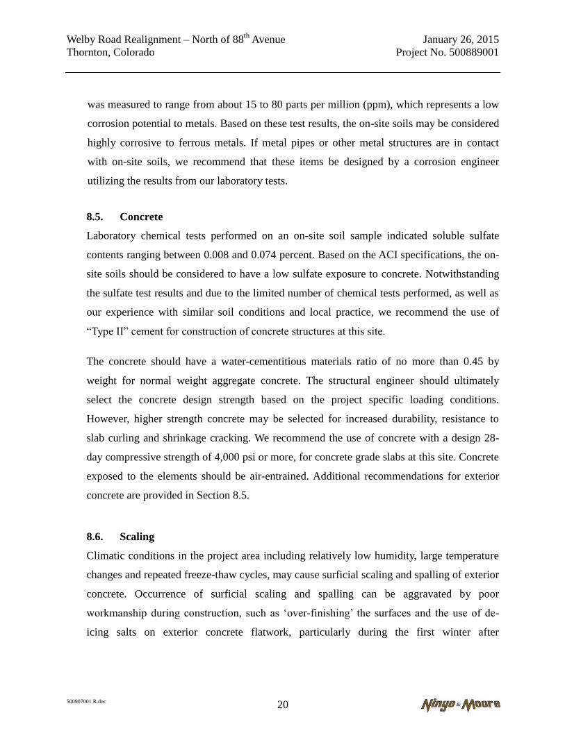
8.5. Concrete
Laboratory chemical tests performed on an on-site soil sample indicated soluble sulfate
contents ranging between 0.008 and 0.074 percent. Based on the ACI specifications, the on-
site soils should be considered to have a low sulfate exposure to concrete. Notwithstanding
the sulfate test results and due to the limited number of chemical tests performed, as well as
our experience with similar soil conditions and local practice, we recommend the use of
“Type II” cement for construction of concrete structures at this site.
The concrete should have a water-cementitious materials ratio of no more than 0.45 by
weight for normal weight aggregate concrete. The structural engineer should ultimately
select the concrete design strength based on the project specific loading conditions.
However, higher strength concrete may be selected for increased durability, resistance to
slab curling and shrinkage cracking. We recommend the use of concrete with a design 28-
day compressive strength of 4,000 psi or more, for concrete grade slabs at this site. Concrete
exposed to the elements should be air-entrained. Additional recommendations for exterior
concrete are provided in Section 8.5.
8.6. Scaling
Climatic conditions in the project area including relatively low humidity, large temperature
changes and repeated freeze-thaw cycles, may cause surficial scaling and spalling of exterior
concrete. Occurrence of surficial scaling and spalling can be aggravated by poor
workmanship during construction, such as ‘over-finishing’ the surfaces and the use of de-
icing salts on exterior concrete flatwork, particularly during the first winter after

Welby Road Realignment – North of 88th
Avenue January 26, 2015
Thornton, Colorado Project No. 500889001
500907001 R.doc 21
construction. The use of de-icing salts on nearby roadways, from where they can be
transferred by vehicle traffic onto newly placed concrete, can be sufficient to induce scaling.
The measures below can be beneficial for reducing the concrete scaling. However, because
of the other factors involved, including workmanship, surface damage to concrete can
develop, where the measures provided below were followed. The mix design criteria should
be coordinated with other project requirements including the criteria for soluble sulfate
resistance presented in Section 8.4.
Curing concrete in accordance with applicable codes and guidelines.
Maintaining a water/cement ratio of 0.45 by weight for exterior concrete mixes.
Including Type F fly ash in exterior concrete mixes as 20 percent of the cementitious
material.
Specifying a 28-day, compressive strength of 4,500 or more psi for exterior concrete.
Including ‘fibermesh’ in the concrete mix.
Avoiding the use of de-icing salts through the first winter after construction.
8.7. Construction in Cold or Wet Weather
During construction, the site should be graded such that surface water can drain readily
away from construction areas. Given the soil conditions, it is important to avoid ponding of
water in or near excavations and surface improvements. Water that accumulates in or near
excavations and surface improvements should be promptly pumped out or otherwise
removed and these areas should be allowed to dry out before resuming construction. Berms,
ditches, and similar means should be used to decrease storm water entering the work area
and to efficiently convey it off site.
Earthwork activities undertaken during the cold weather season may be difficult and should
be done by an experienced contractor. Fill should not be placed on top of frozen soils. The
frozen soils should be removed prior to the placement of new engineered fill or other
construction material. Frozen soil should not be used as structural fill or backfill. The frozen

Welby Road Realignment – North of 88th
Avenue January 26, 2015
Thornton, Colorado Project No. 500889001
500907001 R.doc 22
soil may be reused (provided it meets the selection criteria) once it has thawed completely.
In addition, compaction of the soils may be more difficult due to the viscosity change in
water at lower temperatures.
If construction proceeds during cold weather, aggregate base course, asphalt, and concrete
elements should not be placed on frozen subgrade soil. Frozen soil should either be removed
from beneath these elements, or thawed and re-compacted. To limit the potential for soil
freezing, the time passing between excavation and construction should be minimized.
Blankets, straw, soil cover, or heating could be used to discourage the soil from freezing.
8.8. Construction Plan Review and Pre-Construction Conference
We recommend that the approved construction plans be submitted for review by Ninyo &
Moore to evaluate adherence to the recommendations provided in this report and to provide
supplemental recommendations, as appropriate. We also recommend that a pre-construction
conference be held with the owner or agency representative, geotechnical consultant, civil
engineer, and contractor in attendance.
8.9. Construction Observation
The conclusions and recommendations presented in this report are based on analysis of
observed conditions in widely spaced exploratory borings. If conditions are found to vary
from those described in this report, Ninyo & Moore should be notified and additional
recommendations will be provided upon request. We recommend that Ninyo & Moore
observe and test fill placement and compaction. Project plans should also be reviewed by
Ninyo & Moore prior to the start of construction.
The recommendations provided in this report are based on the assumption that Ninyo &
Moore will provide geotechnical observation and testing services during the construction
phase of the project. In the event that Ninyo & Moore’s services are not used during
construction, we request that the selected consultant provide a letter to the client (with a
copy to Ninyo & Moore) indicating that they fully understand Ninyo & Moore’s

Welby Road Realignment – North of 88th
Avenue January 26, 2015
Thornton, Colorado Project No. 500889001
500907001 R.doc 23
recommendations, and that they are in full agreement with the recommendations contained
in this report.
9. LIMITATIONS
The field evaluation, laboratory testing, and geotechnical analyses presented in this geotechnical
report have been conducted in general accordance with current practice and the standard of care
exercised by geotechnical consultants performing similar tasks in the project area. No warranty,
expressed or implied, is made regarding the conclusions, recommendations, and opinions
presented in this report. There is no evaluation detailed enough to reveal every subsurface
condition. Variations may exist and conditions not observed or described in this report may be
encountered during construction. Uncertainties relative to subsurface conditions can be reduced
through additional subsurface exploration. Additional subsurface evaluation will be performed
upon request. Please also note that our evaluation was limited to assessment of the geotechnical
aspects of the project, and did not include evaluation of structural issues, environmental
concerns, or the presence of hazardous materials.
This document is intended to be used only in its entirety. No portion of the document, by itself, is
designed to completely represent any aspect of the project described herein. Ninyo & Moore
should be contacted if the reader requires additional information or has questions regarding the
content, interpretations presented, or completeness of this document.
This report is intended for design purposes only. It does not provide sufficient data to prepare an
accurate bid by contractors. It is suggested that the bidders and their geotechnical consultant
perform an independent evaluation of the subsurface conditions in the project areas. The
independent evaluations may include, but not be limited to, review of other geotechnical reports
prepared for the adjacent areas, site reconnaissance, and additional exploration and laboratory
testing.
Our conclusions, recommendations, and opinions are based on an analysis of the observed site
conditions. If geotechnical conditions different from those described in this report are
Welby Road Realignment – North of 88th
Avenue January 26, 2015
Thornton, Colorado Project No. 500889001
500907001 R.doc 24
encountered, our office should be notified and additional recommendations, if warranted, will be
provided upon request. It should be understood that the conditions of a site could change with
time as a result of natural processes or the activities of man at the subject site or nearby sites. In
addition, changes to the applicable laws, regulations, codes, and standards of practice may occur
due to government action or the broadening of knowledge. The findings of this report may,
therefore, be invalidated over time, in part or in whole, by changes over which Ninyo & Moore
has no control.
This report is intended exclusively for use by the client. Any use or reuse of the findings,
conclusions, and/or recommendations of this report by parties other than the client is undertaken
at said parties’ sole risk.

Welby Road Realignment – North of 88th
Avenue January 26, 2015
Thornton, Colorado Project No. 500889001
500907001 R.doc 25
10. REFERENCES
American Society for Testing and Materials (ASTM), 2010 Annual Book of ASTM Standards.
City of Thornton, 2012, Standards and Specifications, dated October.
Colorado Department of Transportation (CDOT), 2015, Pavement Design Manual.
Colorado Department of Transportation (CDOT), 2012, M&S Standards, dated July 4.
Colorado Department of Transportation (CDOT), 2011, Standard Specifications for Road and
Bridge Construction.
Hart, Stephen S., 1973-4, Potentially Swelling Soil and Rock in the Front Range Urban Corridor,
Colorado: Colorado Geological Survey, Sheet 1 of 4.
Trimble, Donald E., 1980, The Geologic Story of the Great Plains, Geological Survey Bulletin
1493.
Trimble, Donald E. and Machette, Michael M., 1979, Geologic Map of the Greater Denver Area,
Front Range Urban Corridor, Colorado: United States Geological Survey.
Aerial Photograph References
Source Dates
Google Earth September, 1994; December 2002; November 2006,
July, 2007, June, 2014.
N
APPROXIMATESITE LOCATION
SITE LOCATIONFIGURE
1DATE:
1/15
file no: 0907vmap0115
PROJECT NO:
500907001
WELBY ROAD REALIGNMENTTHORNTON, COLORADO
Source: Macvan Map Company, Denver, Colorado, 2011.
APPROXIMATESITE LOCATION
N
N
APPROXIMATESITE LOCATION
APPROXIMATE LOCATIONOF STOCKPILES
Source: Macvan Map Company, Denver, Colorado, 2011.
APPROXIMATESITE LOCATION
APPROXIMATESITE LOCATION
0
Ap p ro x i ma te Sca l e :1 i n ch = 20 0 0 f e e t
2000
Note: Dimensions, directions and locations are approximate.
APPROXIMATESITE LOCATION
Source: US Geological Survey 7.5-minute topographic map, Fort Morgan, Colorado, 1982, rev. 1984.
Source: Macvan Map Company, Denver, Colorado, 2011.
N
APPROXIMATESITE LOCATION

Note: Dimensions, directions, and locations are approximate.
LEGEND
Boring LocationB-2
LEGEND
Boring LocationB-2 Source: SPOT IMAGE, 10/06/14.
file
no
: 0
90
7b
lm0
115
0
Ap p ro x i ma te Sca l e :1 i n ch = 25 0
N
FIGURE
2DATE:
1/15
PROJECT NO:
500907001 THORNTON, COLORADOWELBY ROAD REALIGNMENT
BORING LOCATIONS250
LEGEND
Boring LocationB-6
B-2
B-1B-4
B-5
B-3
B-6
WELBY R
OAD
88TH AVENUE
BEACHWOOD DRIVE
B-1
B-2
B-3
B-4

Welby Road Realignment – North of 88th
Avenue January 26, 2015
Thornton, Colorado Project No. 500889001
500907001 R.doc
APPENDIX A
BORING LOGS
Field Procedure for the Collection of Disturbed Samples
Disturbed soil samples were obtained in the field using the following methods.
Bulk Samples
Bulk samples of representative earth materials were obtained from the exploratory borings. The
samples were bagged and transported to the laboratory for testing.
Field Procedure for the Collection of Relatively Undisturbed Samples
Relatively undisturbed soil samples were obtained in the field using the following methods.
The Modified California Split-Barrel Drive Sampler
The sampler, with an external diameter of 3.0 inches, was lined with thin brass rings with inside
diameters of approximately 2.4 inches. The sample barrel was driven into the ground with the
weight of a hammer in general accordance with ASTM D 3550. The driving weight was
permitted to fall freely. The approximate length of the fall, the weight of the hammer or bar, and
the number of blows per foot of driving are presented on the boring logs as an index to the
relative resistance of the materials sampled. The samples were removed from the sample barrel
in the brass rings, sealed, and transported to the laboratory for testing.
The California Drive Sampler
The sampler, with an external diameter of 2.4 inches, was lined with four 4-inch long, thin brass
liners with inside diameters of approximately 1.9 inches. The sample barrel was driven into the
ground with the weight of a hammer in general accordance with ASTM D 3550. The driving
weight was permitted to fall freely. The approximate length of the fall, the weight of the
hammer, and the number of blows per foot of driving are presented on the boring logs as an
index to the relative resistance of the materials sampled. The samples were removed from the
sample barrel in the brass liners, sealed, and transported to the laboratory for testing.

SOIL CLASSIFICATION CHART PER ASTM D 2488
PRIMARY DIVISIONSSECONDARY DIVISIONS
GROUP SYMBOL GROUP NAME
COARSE- GRAINED
SOILS more than
50% retained on No. 200
sieve
GRAVEL more than
50% of coarse fraction
retained on No. 4 sieve
CLEAN GRAVELless than 5% fines
GW well-graded GRAVEL
GP poorly graded GRAVEL
GRAVEL with DUAL
CLASSIFICATIONS 5% to 12% fines
GW-GM well-graded GRAVEL with silt
GP-GM poorly graded GRAVEL with silt
GW-GC well-graded GRAVEL with clay
GP-GC poorly graded GRAVEL with clay
GRAVEL with FINES
more than 12% fines
GM silty GRAVEL
GC clayey GRAVEL
GC-GM silty, clayey GRAVEL
SAND 50% or more
of coarse fraction passes
No. 4 sieve
CLEAN SAND less than 5% fines
SW well-graded SAND
SP poorly graded SAND
SAND with DUAL
CLASSIFICATIONS 5% to 12% fines
SW-SM well-graded SAND with silt
SP-SM poorly graded SAND with silt
SW-SC well-graded SAND with clay
SP-SC poorly graded SAND with clay
SAND with FINES more than 12% fines
SM silty SAND
SC clayey SAND
SC-SM silty, clayey SAND
FINE- GRAINED
SOILS 50% or
more passes No. 200 sieve
SILT and CLAY
liquid limit less than 50%
INORGANIC
CL lean CLAY
ML SILT
CL-ML silty CLAY
ORGANICOL (PI > 4) organic CLAY
OL (PI < 4) organic SILT
SILT and CLAY
liquid limit 50% or more
INORGANICCH fat CLAY
MH elastic SILT
ORGANIC
OH (plots on or above “A”-line) organic CLAY
OH (plots below “A”-line) organic SILT
Highly Organic Soils PT Peat
USCS METHOD OF SOIL CLASSIFICATIONExplanation of USCS Method of Soil Classification
PROJECT NO. DATE FIGURE
APPARENT DENSITY - COARSE-GRAINED SOIL
APPARENT DENSITY
SPOOLING CABLE OR CATHEAD AUTOMATIC TRIP HAMMER
SPT (blows/foot)
MODIFIED SPLIT BARREL
(blows/foot)SPT
(blows/foot)MODIFIED
SPLIT BARREL (blows/foot)
Very Loose < 4 < 8 < 3 < 5
Loose 5 - 10 9 - 21 4 - 7 6 - 14
Medium Dense 11 - 30 22 - 63 8 - 20 15 - 42
Dense 31 - 50 64 - 105 21 - 33 43 - 70
Very Dense > 50 > 105 > 33 > 70
CONSISTENCY - FINE-GRAINED SOIL
CONSIS-TENCY
SPOOLING CABLE OR CATHEAD AUTOMATIC TRIP HAMMER
SPT (blows/foot)
MODIFIED SPLIT BARREL
(blows/foot)SPT
(blows/foot)MODIFIED
SPLIT BARREL (blows/foot)
Very Soft < 2 < 3 < 1 < 2
Soft 2 - 4 3 - 5 1 - 3 2 - 3
Firm 5 - 8 6 - 10 4 - 5 4 - 6
Stiff 9 - 15 11 - 20 6 - 10 7 - 13
Very Stiff 16 - 30 21 - 39 11 - 20 14 - 26
Hard > 30 > 39 > 20 > 26
LIQUID LIMIT (LL), %
PLA
STI
CIT
Y IN
DE
X (
PI)
, %
0 10
1074
20
30
40
50
60
70
020 30 40 50 60 70 80 90 100
MH or OH
ML or OLCL - ML
PLASTICITY CHART
GRAIN SIZE
DESCRIPTION SIEVE SIZE
GRAIN SIZE
APPROXIMATE SIZE
Boulders > 12” > 12” Larger than basketball-sized
Cobbles 3 - 12” 3 - 12” Fist-sized to basketball-sized
Gravel
Coarse 3/4 - 3” 3/4 - 3” Thumb-sized to fist-sized
Fine #4 - 3/4” 0.19 - 0.75” Pea-sized to thumb-sized
Sand
Coarse #10 - #4 0.079 - 0.19” Rock-salt-sized to pea-sized
Medium #40 - #10 0.017 - 0.079” Sugar-sized to rock-salt-sized
Fine #200 - #40 0.0029 - 0.017”
Flour-sized to sugar-sized
Fines Passing #200 < 0.0029” Flour-sized and smaller
CH or OH
CL or OL

BORING LOG EXPLANATION SHEET
0
5
XX/XX
10
15
Bulk sample.
Modified split-barrel drive sampler.
2-inch inner diameter split-barrel drive sampler.
No recovery with modified split-barrel drive sampler, or 2-inch inner diameter split-barrel drive sampler.
Sample retained by others.
Standard Penetration Test (SPT).
No recovery with a SPT.
Shelby tube sample. Distance pushed in inches/length of sample recovered in inches.
No recovery with Shelby tube sampler.
Continuous Push Sample.
Seepage. Groundwater encountered during drilling. Groundwater measured after drilling.
SM MAJOR MATERIAL TYPE (SOIL):Solid line denotes unit change.
CL Dashed line denotes material change.
Attitudes: Strike/Dip b: Bedding c: Contact j: Joint f: Fracture F: Fault cs: Clay Seam s: Shear bss: Basal Slide Surface sf: Shear Fracture sz: Shear Zone sbs: Shear Bedding Surface
The total depth line is a solid line that is drawn at the bottom of the boring.
20
BORING LOGExplanation of Boring Log Symbols
PROJECT NO. DATE FIGURE
DE
PTH
(feet
)
BLO
WS
/FO
OT
MO
ISTU
RE
(%)
DR
YD
EN
SIT
Y(P
CF)
CLA
SS
IFIC
ATI
ON
U
.S.C
.S.

0
10
20
30
40
18
14
25.0 96.4
CL
SC
ALLUVIUM:Brown, dry to moist, very stiff, lean CLAY with sand.
Light brown to brown, moist, medium dense, clayey SAND.
Total Depth = 8.5 feet.Groundwater not encountered during drilling.Backfilled on 12/29/14 shorthly after completion of drilling.Notes:Groundwater, though not encoutered at the time of drilling, may rise to a higher level dueto seasonal variations in precipitation and several other factors as discussed in the report.The ground elevation shown above is an estimation only. It is based on our interpretationsof published maps and other documents reviewed for the purposes of this evaluation. It isnot sufficiently accurate for preparing construction bids and design documents.
BORING LOGWELBY ROAD REALIGNMENT
THORNTON, COLORADO
PROJECT NO.
500907001
DATE
01/15
FIGURE
A-1
DE
PT
H (
fee
t)
Bu
lkS
AM
PL
ES
Dri
ve
n
BL
OW
S/F
OO
T
MO
IST
UR
E (
%)
DR
Y D
EN
SIT
Y (
PC
F)
SY
MB
OL
CL
AS
SIF
ICA
TIO
N
U.S
.C.S
.
DESCRIPTION/INTERPRETATION
DATE DRILLED December 29, 2014 BORING NO. B-1
GROUND ELEVATION 5,126± SHEET 1 OF
METHOD OF DRILLING CME-55, Truck Rig, 4" Solid Stem Augers (Elite Drilling)
DRIVE WEIGHT 140 lbs - Auto Hammer DROP 30"
SAMPLED BY JF LOGGED BY JF REVIEWED BY JMJ
1

0
10
20
30
40
16
17
27.1 96.9
CL ALLUVIUM:Brown, moist, very stiff, sandy CLAY, trace gravel.
Light brown to brown.
Total Depth = 8.5 feet.Groundwater not encountered during drilling.Backfilled on 12/29/14 shorthly after completion of drilling.Notes:Groundwater, though not encoutered at the time of drilling, may rise to a higher level dueto seasonal variations in precipitation and several other factors as discussed in the report.The ground elevation shown above is an estimation only. It is based on our interpretationsof published maps and other documents reviewed for the purposes of this evaluation. It isnot sufficiently accurate for preparing construction bids and design documents.
BORING LOGWELBY ROAD REALIGNMENT
THORNTON, COLORADO
PROJECT NO.
500907001
DATE
01/15
FIGURE
A-2
DE
PT
H (
fee
t)
Bu
lkS
AM
PL
ES
Dri
ve
n
BL
OW
S/F
OO
T
MO
IST
UR
E (
%)
DR
Y D
EN
SIT
Y (
PC
F)
SY
MB
OL
CL
AS
SIF
ICA
TIO
N
U.S
.C.S
.
DESCRIPTION/INTERPRETATION
DATE DRILLED December 29, 2014 BORING NO. B-2
GROUND ELEVATION 5,127± SHEET 1 OF
METHOD OF DRILLING CME-55, Truck Rig, 4" Solid Stem Augers (Elite Drilling)
DRIVE WEIGHT 140 lbs - Auto Hammer DROP 30"
SAMPLED BY JF LOGGED BY JF REVIEWED BY JMJ
1

0
10
20
30
40
15
36
26.0 96.1
CH ALLUVIUM:Light brown to brown, moist, very stiff, fat CLAY.
Hard.
Total Depth = 8.5 feet.Groundwater not encountered during drilling.Backfilled on 12/29/14 shorthly after completion of drilling.Notes:Groundwater, though not encoutered at the time of drilling, may rise to a higher level dueto seasonal variations in precipitation and several other factors as discussed in the report.The ground elevation shown above is an estimation only. It is based on our interpretationsof published maps and other documents reviewed for the purposes of this evaluation. It isnot sufficiently accurate for preparing construction bids and design documents.
BORING LOGWELBY ROAD REALIGNMENT
THORNTON, COLORADO
PROJECT NO.
500907001
DATE
01/15
FIGURE
A-3
DE
PT
H (
fee
t)
Bu
lkS
AM
PL
ES
Dri
ve
n
BL
OW
S/F
OO
T
MO
IST
UR
E (
%)
DR
Y D
EN
SIT
Y (
PC
F)
SY
MB
OL
CL
AS
SIF
ICA
TIO
N
U.S
.C.S
.
DESCRIPTION/INTERPRETATION
DATE DRILLED December 29, 2014 BORING NO. B-3
GROUND ELEVATION 5,132± SHEET 1 OF
METHOD OF DRILLING CME-55, Truck Rig, 4" Solid Stem Augers (Elite Drilling)
DRIVE WEIGHT 140 lbs - Auto Hammer DROP 30"
SAMPLED BY JF LOGGED BY JF REVIEWED BY JMJ
1

0
10
20
30
40
32
20
18.6
16.3
106.9
106.3
SM
CH
SC
FILL:Brown, moist, loose to medium dense, silty SAND, varying amounts of gravel andconstruction debris.At 2', concrete encountered, hole caved in 3 times, offset 4' South.At 3.5', concrete and caving in, offset 5' Northeast twice.
ALLUVIUM:Light brown to brown, moist, very stiff, fat CLAY.
Light brown to brown, moist, medium dense, clayey SAND.
Total Depth = 8.5 feet.Groundwater not encountered during drilling.Backfilled on 12/29/14 shorthly after completion of drilling.Notes:Groundwater, though not encoutered at the time of drilling, may rise to a higher level dueto seasonal variations in precipitation and several other factors as discussed in the report.The ground elevation shown above is an estimation only. It is based on our interpretationsof published maps and other documents reviewed for the purposes of this evaluation. It isnot sufficiently accurate for preparing construction bids and design documents.
BORING LOGWELBY ROAD REALIGNMENT
THORNTON, COLORADO
PROJECT NO.
500907001
DATE
01/15
FIGURE
A-4
DE
PT
H (
fee
t)
Bu
lkS
AM
PL
ES
Dri
ve
n
BL
OW
S/F
OO
T
MO
IST
UR
E (
%)
DR
Y D
EN
SIT
Y (
PC
F)
SY
MB
OL
CL
AS
SIF
ICA
TIO
N
U.S
.C.S
.
DESCRIPTION/INTERPRETATION
DATE DRILLED December 29, 2014 BORING NO. B-4
GROUND ELEVATION 5,135± SHEET 1 OF
METHOD OF DRILLING CME-55, Truck Rig, 4" Solid Stem Augers (Elite Drilling)
DRIVE WEIGHT 140 lbs - Auto Hammer DROP 30"
SAMPLED BY JF LOGGED BY JF REVIEWED BY JMJ
1

Welby Road Realignment – North of 88th
Avenue January 26, 2015
Thornton, Colorado Project No. 500889001
500907001 R.doc
APPENDIX B
LABORATORY TESTING
Classification
Soils were visually and texturally classified in accordance with the Unified Soil Classifications
System (USCS) in general accordance with ASTM D 2488. Soil classifications are indicated on the
logs of the exploratory excavations in Appendix A.
In-Place Moisture and Density Tests
The moisture content and dry density of relatively undisturbed samples obtained from the exploratory
excavations were evaluated in general accordance with ASTM D 2937-00. The test results are
presented on the logs of the exploratory excavations in Appendix A.
Atterberg Limits
Tests were performed on selected representative fine-grained soil samples to evaluate the liquid limit,
plastic limit, and plasticity index in general accordance with ASTM D 4318. These test results were
utilized to evaluate the soil classification in accordance with the Unified Soil Classification System.
The test results and classifications are shown on Figure B-1.
No. 200 Sieve Analysis
An evaluation of the percentage of particles finer than the No. 200 sieve in selected soil samples was
performed in general accordance with ASTM D 1140. The results of the tests are presented on Figure
B-2.
Gradation Analysis
Gradation analysis tests were performed on selected representative soil samples in general
accordance with ASTM D 422. The test results were utilized in evaluating the soil classifications in
accordance with the Unified Soil Classification System. The grain-size distribution curves are shown
on Figures B-4 and B-5.
Swell Potential Tests
The swell potential of selected materials was evaluated in general accordance with ASTM D 4546.
Relatively undisturbed and remolded specimens were loaded with a specified surcharge before
inundation with water. Readings of volumetric swell were recorded until completion of primary
swell. After the completion of primary swell, surcharge loads were increased incrementally to
evaluate swell pressure. The results of the swell tests performed on relatively undisturbed samples
are presented on Figures B-6 and B-7.
Soil Corrosivity Tests
Soil pH tests were performed on representative samples in general accordance with ASTM Test
Method D 4972. Soil minimum resistivity tests were performed on representative samples in general
accordance with AASHTO T288. The sulfate content of selected sample was evaluated in general
accordance with CDOT Test Method CP-L 2103. The chloride content of selected samples was

Welby Road Realignment – North of 88th
Avenue January 26, 2015
Thornton, Colorado Project No. 500889001
500907001 R.doc
evaluated in general accordance with CDOT Test Method CP-L 2104. The test results are presented
on Figure B-8.
R-Value Tests
The resistance R-value and expansion pressure of selected representative compacted soil samples
were evaluated in general accordance with ASTM D 2844. The results of the tests are summarized on
Figure B-9.


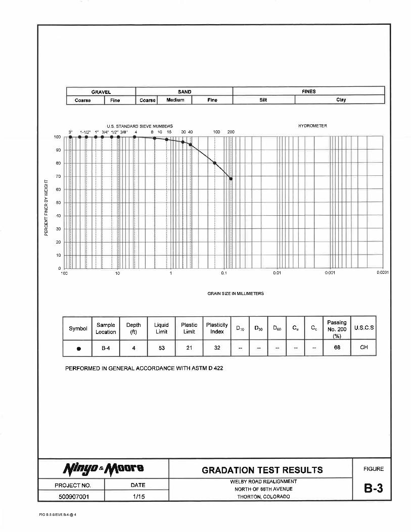


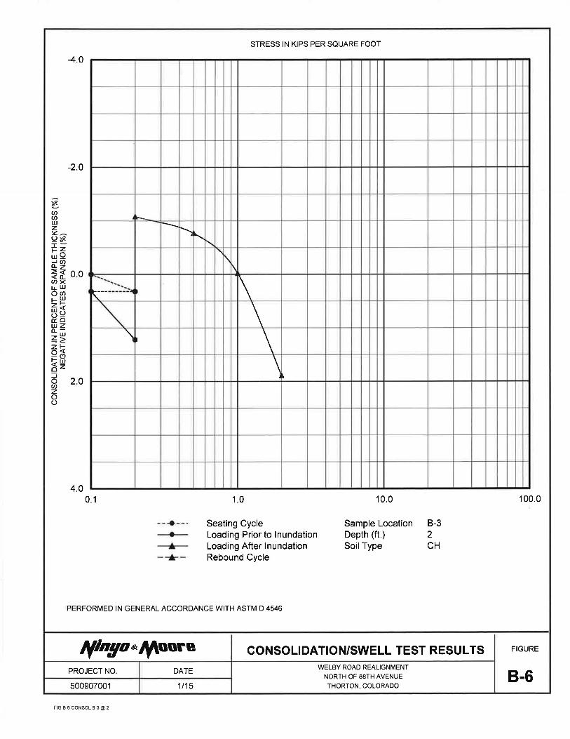
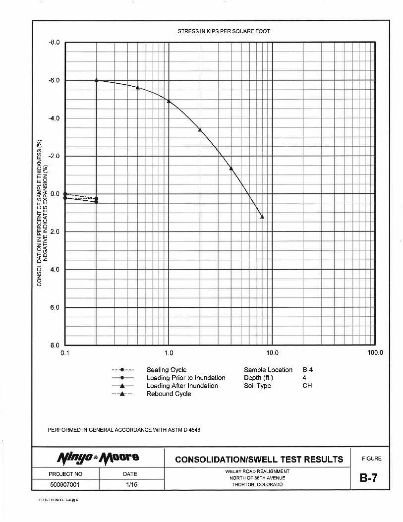


Welby Road Realignment – North of 88th
Avenue January 26, 2015
Thornton, Colorado Project No. 500889001
500907001 R.doc
APPENDIX C
FLEXIBLE PAVEMENT CALCULATIONS
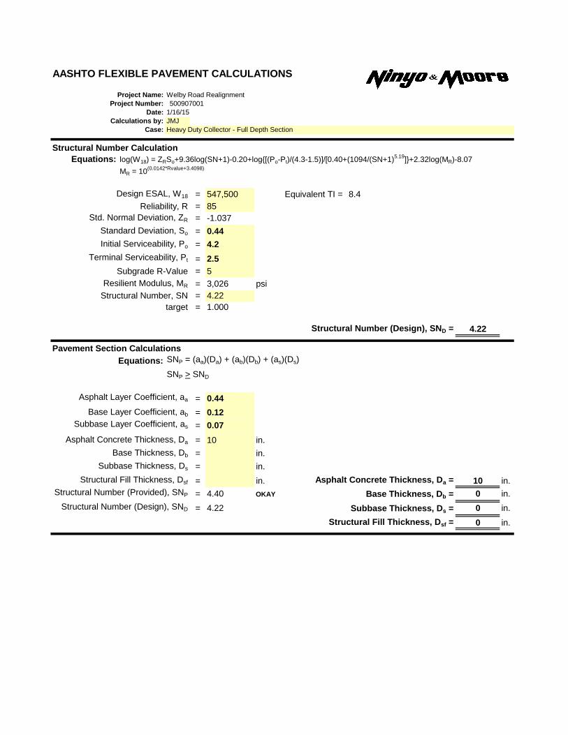
AASHTO FLEXIBLE PAVEMENT CALCULATIONS
Project Name: Welby Road Realignment
Project Number:
Date: 1/16/15
Calculations by: JMJ
Case:
Structural Number Calculation
Equations: log(W18) = ZRSo+9.36log(SN+1)-0.20+log{[(Po-Pt)/(4.3-1.5)]/[0.40+(1094/(SN+1)5.19
]}+2.32log(MR)-8.07
MR = 10(0.0142*Rvalue+3.4098)
Design ESAL, W18 = 547,500 Equivalent TI = 8.4
Reliability, R = 85
Std. Normal Deviation, ZR = -1.037
Standard Deviation, So = 0.44
Initial Serviceability, Po = 4.2
Terminal Serviceability, Pt = 2.5
Subgrade R-Value = 5
Resilient Modulus, MR = 3,026 psi
Structural Number, SN = 4.22
target = 1.000
Structural Number (Design), SND = 4.22
Pavement Section Calculations
Equations: SNP = (aa)(Da) + (ab)(Db) + (as)(Ds)
SNP > SND
Asphalt Layer Coefficient, aa = 0.44
Base Layer Coefficient, ab = 0.12
Subbase Layer Coefficient, as = 0.07
Asphalt Concrete Thickness, Da = 10 in.
Base Thickness, Db = in.
Subbase Thickness, Ds = in.
Structural Fill Thickness, Dsf = in. Asphalt Concrete Thickness, Da = 10 in.
Structural Number (Provided), SNP = 4.40 OKAY Base Thickness, Db = 0 in.
Structural Number (Design), SND = 4.22 Subbase Thickness, Ds = 0 in.
Structural Fill Thickness, Dsf = 0 in.
Heavy Duty Collector - Full Depth Section
500907001

AASHTO FLEXIBLE PAVEMENT CALCULATIONS
Project Name: Welby Road Realignment
Project Number:
Date: 1/16/15
Calculations by: JMJ
Case:
Structural Number Calculation
Equations: log(W18) = ZRSo+9.36log(SN+1)-0.20+log{[(Po-Pt)/(4.3-1.5)]/[0.40+(1094/(SN+1)5.19
]}+2.32log(MR)-8.07
MR = 10(0.0142*Rvalue+3.4098)
Design ESAL, W18 = 547,500 Equivalent TI = 8.4
Reliability, R = 85
Std. Normal Deviation, ZR = -1.037
Standard Deviation, So = 0.44
Initial Serviceability, Po = 4.2
Terminal Serviceability, Pt = 2.5
Subgrade R-Value = 5
Resilient Modulus, MR = 3,026 psi
Structural Number, SN = 4.22
target = 1.000
Structural Number (Design), SND = 4.22
Pavement Section Calculations
Equations: SNP = (aa)(Da) + (ab)(Db) + (as)(Ds)
SNP > SND
Asphalt Layer Coefficient, aa = 0.44
Base Layer Coefficient, ab = 0.12
Subbase Layer Coefficient, as = 0.07
Asphalt Concrete Thickness, Da = 7 in.
Base Thickness, Db = 10 in.
Subbase Thickness, Ds = in.
Structural Fill Thickness, Dsf = in. Asphalt Concrete Thickness, Da = 7 in.
Structural Number (Provided), SNP = 4.28 OKAY Base Thickness, Db = 10 in.
Structural Number (Design), SND = 4.22 Subbase Thickness, Ds = 0 in.
Structural Fill Thickness, Dsf = 0 in.
Heavy Duty Collector - Composite Section
500907001