Embed Size (px)
Citation preview

GEOTECHNICAL EVALUATION
SIM’S RANCH – FM 2590
CANYON, TX
BRAUN INTERTEC CORPORATION
PROJECT NO. B1602449
Prepared For:
Gregg Bliss Architect
1001 SE 3rd
Amarillo, TX 79102
806.372.2966
Prepared By:
Braun Intertec Corporation
TBPE Firm No. F-12228
(800) 755-8461
www.braunintertec.com
©May 2016
Apex Geoscience 215 S. Fannin Amarillo, TX 79106
Phone: 806.677.0600 Fax: 855.581.8081 Web: apexgeo.com
May 20, 2016
Gregg Bliss Architect
1001 SE 3rd
Amarillo, TX 79102
806.372.2966
RE: Geotechnical Evaluation
Sim’s Ranch – FM 2590 – Canyon, TX
Braun Intertec Corporation Project No. B1602449
Mr. Bliss:
Braun Intertec Corporation (includes Apex Geoscience, a division of Braun Intertec) is pleased to
submit this report of subsurface exploration for the above referenced project. Included in the report
are the results of the exploration and recommendations concerning the design and construction of
the foundations as well as general site development.
We appreciate the opportunity to have provided you with our geotechnical engineering services
and look forward to the opportunity of providing any materials testing required during
construction. Please contact Steve Camargo in our Amarillo, TX Office at 806.677.0600 for those
services. If you have any questions concerning this report, or if we may be of further service, please
contact our office.
Respectfully submitted, Braun Intertec Corporation
Shane Nance, P.E. Wm. Duane Harrell, P.E., LEED AP
Associate Principal/Senior Engineer Associate Principal/Senior Engineer
[email protected] [email protected]
806.677.0600 | 215 South Fannin; Amarillo, Texas 79424 apexgeo.com
●●●●●●●●●●●●●●●●●●●●●●●●●●●●●●●●●●●●●●●●●●●●●●●●●●●●●●●●●●●●●●●●●●●●●●●●●●
The seal appearing on this document was authorized by
Shane Nance, P.E. 81519 on May 20, 2016.
TABLE OF CONTENTS
1.0 INTRODUCTION....................................................................................................................1 1.1 Project Authorization ........................................................................................................1 1.2 Purpose ..............................................................................................................................1 1.3 Report Limitation ..............................................................................................................1
2.0 PROJECT DESCRIPTION ....................................................................................................2 2.1 Project Description ............................................................................................................2 2.2 Loading Criteria ................................................................................................................2 2.3 Allowable Movement Criteria ...........................................................................................2 2.4 Grade Changes ..................................................................................................................2
2.5 Information Note ...............................................................................................................3
3.0 TESTING PROCEDURES .....................................................................................................4 3.1 Field Operations ................................................................................................................4 3.2 Laboratory Testing ............................................................................................................4
3.3 Sample Retention ..............................................................................................................5
4.0 SITE AND SUBSURFACE CONDITIONS ..........................................................................6 4.1 Site Description .................................................................................................................6 4.2 Subsurface Conditions.......................................................................................................6 4.3 Groundwater Conditions ...................................................................................................7
5.0 FOUNDATION RECOMMENDATIONS ............................................................................8 5.1 General ..............................................................................................................................8
5.2 Grading and Site Drainage ................................................................................................9 5.3 Foundation Subgrade Preparation .....................................................................................9 5.4 Shallow Foundation.........................................................................................................10
5.5 Floor Slab and Grade Beam Considerations ...................................................................11 5.6 OSHA Soil Classifications ..............................................................................................12
5.7 IBC Seismic Site Coefficient ..........................................................................................12
6.0 CONSTRUCTION CONSIDERATIONS ...........................................................................13 6.1 Site Preparation ...............................................................................................................13 6.2 Select Fill.........................................................................................................................13
6.3 Safety Considerations ......................................................................................................15 6.4 Worker Safety - Excavations and Slopes ........................................................................15 6.5 Inclement Weather Considerations .................................................................................16 6.6 Protection of Work ..........................................................................................................16
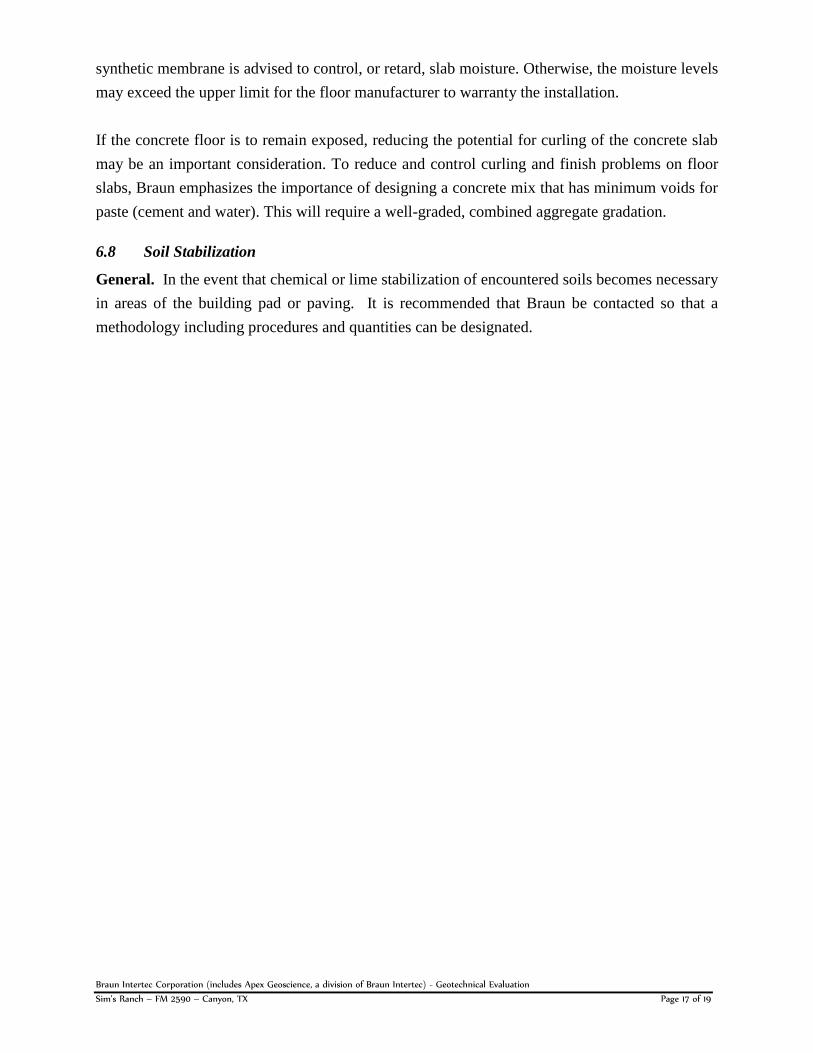
6.7 Membrane Under Slab ....................................................................................................16
7.0 GENERAL COMMENTS .....................................................................................................18
APPENDIX
Plan of Borings
Boring Logs
Terms and Symbols
Braun Intertec Corporation (includes Apex Geoscience, a division of Braun Intertec) - Geotechnical Evaluation Sim’s Ranch – FM 2590 – Canyon, TX Page 1 of 19
1.0 INTRODUCTION
1.1 Project Authorization
Braun Intertec has completed a subsurface exploration and evaluation of soil conditions at the site
of the proposed Sim’s Ranch addition. The proposed project is located southwest of the
intersection of Hunsley Road and FM 2590 in Canyon, TX. Formal authorization to perform the
work was provided by Gregg Bliss by signing the Braun Intertec Proposal. Field activities were
performed on March 25, 2016.
1.2 Purpose
The purpose of this report is to provide the structural engineer, architect, civil engineer, and other
design team professionals with recommendations for the design and construction of the proposed
project. The scope of services for this project included:
1. Determine the various soil profile components;
2. Define the engineering characteristics of the subsurface materials encountered;
3. Observe the groundwater conditions at the site; and
4. Summarize foundation design parameters and construction considerations in a
geotechnical investigation report.
This report also briefly outlines the testing procedures and describes the site and subsurface
conditions.
1.3 Report Limitation
Although this report may be used to produce design concepts and does provide various earthwork
and foundation recommendations, this report should not be used by the contractor in lieu of project
specifications. The findings and recommendations in this report are intended to be interpreted by
professional architectural, structural engineering, and civil engineering consultants.
Braun Intertec Corporation (includes Apex Geoscience, a division of Braun Intertec) - Geotechnical Evaluation Sim’s Ranch – FM 2590 – Canyon, TX Page 2 of 19
2.0 PROJECT DESCRIPTION
2.1 Project Description
Based on information provided by Mr. Bliss, we understand that the project will consist of three
buildings. A brick or masonry exterior veneer is anticipated, and a common floor level is planned
throughout. No above or below grade walls are anticipated at this time.
2.2 Loading Criteria
For the purpose of this report, Braun has assumed the following load criteria:
Maximum column loads will not exceed approximately 50 kips;
Maximum continuous wall loads will be approximately 1 to 2 kips per linear foot; and
Maximum uniform and isolated concentrated floor loads are expected to be 125 psf and 5
kips, respectively.
2.3 Allowable Movement Criteria
For the purpose of this report, unless otherwise stated herein, Braun has assumed a maximum total
vertical movement tolerance of 1 inch. Vertical movement of foundations, covered herein,
specifically addresses movements which may result from either potential settlement or
consolidation of underlying soils under load, or potential shrinkage or heaving conditions resulting
from active clay conditions known to be present in certain regions.
The assumed total vertical movement tolerance was selected based on the standard of care established
in the region for similar projects. Based on past experience, if 1 inch of movement fully develops,
foundation movements may yield visible distress to elements such as exposed concrete surfaces,
masonry, and other features may occur over the life of the project. However, historically such
movements do not yield a structural failure of the foundation system. Although this degree of
movement invokes some risk to the owner, this degree of movement represents a widely-accepted
balance between the risk of distress related to foundation movement, and costs related to controlling
such movement (i.e. site preparation, site mitigation, foundation design and construction). If the
client requires different tolerances for vertical movement, these should be discussed with our
geotechnical engineer prior to finalizing design.
2.4 Grade Changes
Planned grading information was not available for review at the time of this report. It is assumed
that final grade elevations will be relatively consistent with existing grades, grade changes are
expected to be a nominal 2 to 3 feet maximum. If significantly different grade changes are
anticipated, these should be discussed with our geotechnical engineer prior to finalizing design.
Braun Intertec Corporation (includes Apex Geoscience, a division of Braun Intertec) - Geotechnical Evaluation Sim’s Ranch – FM 2590 – Canyon, TX Page 3 of 19
2.5 Information Note
Other than as assumed and stated above, detailed information on structural systems and planned
grading was not available to Braun at the time this report was prepared. If any of this information
should change significantly or be in error, it should be brought to the attention of Braun so that a
review of the provided recommendations can be made.
Braun Intertec Corporation (includes Apex Geoscience, a division of Braun Intertec) - Geotechnical Evaluation Sim’s Ranch – FM 2590 – Canyon, TX Page 4 of 19
3.0 TESTING PROCEDURES
3.1 Field Operations
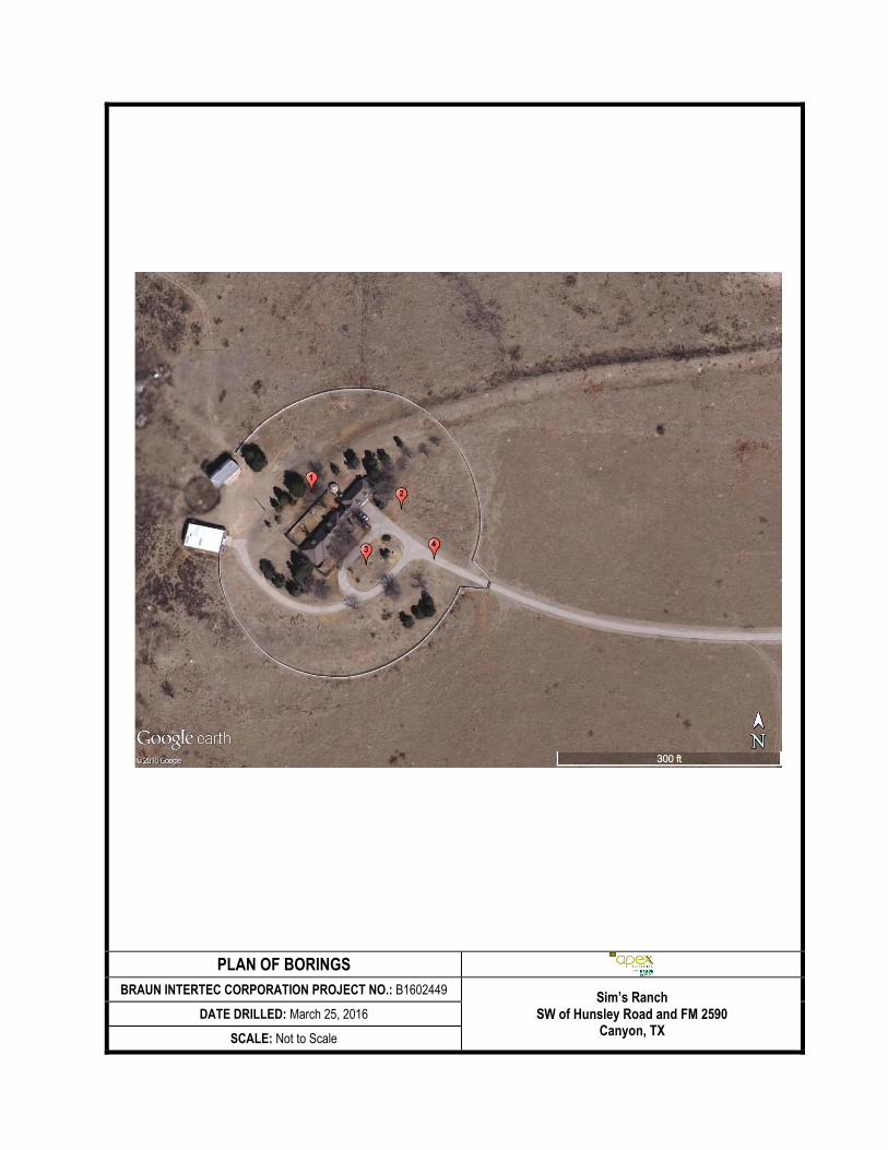
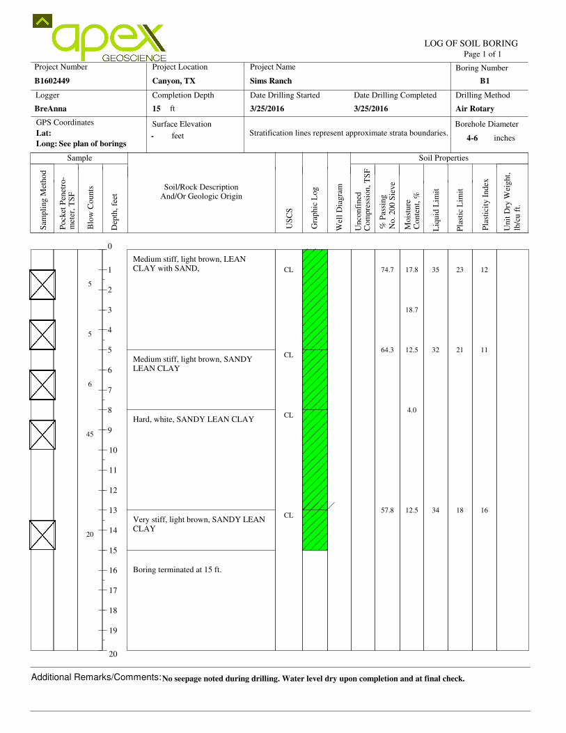
Field Activities. Subsurface conditions were explored by drilling a total of 4 borings to an
approximate depth of 15 feet. Borings were located in the field by the drilling crew prior to drilling
activities. Approximate boring locations are shown on the Plan of Borings included in the
Appendix of this report.
Drilling. The borings were advanced by a CME 75 truck mounted rig using solid flight augers.
Drilling and sampling activities were performed in general accordance with referenced ASTM
procedures or other accepted methods.
Soil Sampling and Penetration Resistance Testing. Split-spoon sampling procedures (Standard
Penetration Test) performed in general accordance with ASTM Standard Method D1586, were
used to collect disturbed soil samples and monitor penetration resistance. Samples were obtained
at selected depths in the test borings by driving a standard 2 inch OD split-spoon sampler 18 inches
(where possible) into the subsurface materials using an automatic falling hammer. The penetration
resistance or "N-Value" is related to the number of hammer blows required to drive the sampler
the final 12 inches, and when properly evaluated, can be used as an index for cohesion for clays,
and relative density for sands.
Soil samples were generally obtained from the ground surface to a depth of about 10 feet using
semi-continuous sampling techniques and at maximum 5 foot intervals thereafter.
Boring Logs. Boring logs which include soil descriptions, water level information, laboratory test
data, stratifications, penetration resistance, classifications based on the Unified Soil Classification
System (USCS) and sample types and depths are included in the Appendix. A key to descriptive
terms and symbols used on the boring logs is also presented in the Appendix.
3.2 Laboratory Testing
The soil samples obtained during the field exploration were transported to the laboratory and
examined by qualified geotechnical personnel. Representative samples were selected and tested to
determine classification properties and particular engineering characteristics. Tests were
performed in general accordance with referenced ASTM procedures or with other accepted
laboratory methods. The results of these tests are presented on the boring logs, at the corresponding
sample depths, included in the Appendix. Laboratory tests performed for this investigation
included the following:
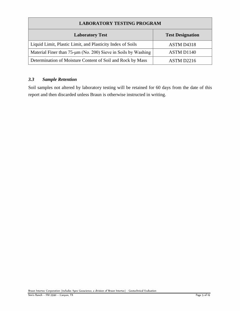
Braun Intertec Corporation (includes Apex Geoscience, a division of Braun Intertec) - Geotechnical Evaluation Sim’s Ranch – FM 2590 – Canyon, TX Page 5 of 19
LABORATORY TESTING PROGRAM
Laboratory Test Test Designation
Liquid Limit, Plastic Limit, and Plasticity Index of Soils ASTM D4318
Material Finer than 75-μm (No. 200) Sieve in Soils by Washing ASTM D1140
Determination of Moisture Content of Soil and Rock by Mass ASTM D2216
3.3 Sample Retention
Soil samples not altered by laboratory testing will be retained for 60 days from the date of this
report and then discarded unless Braun is otherwise instructed in writing.
Braun Intertec Corporation (includes Apex Geoscience, a division of Braun Intertec) - Geotechnical Evaluation Sim’s Ranch – FM 2590 – Canyon, TX Page 6 of 19
4.0 SITE AND SUBSURFACE CONDITIONS
4.1 Site Description
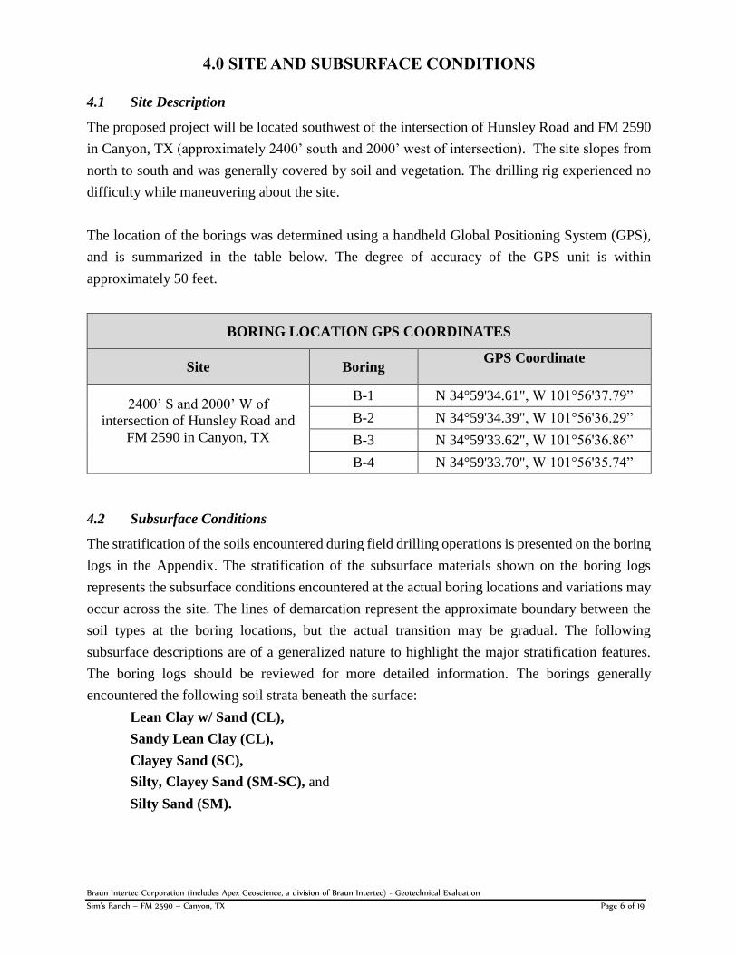
The proposed project will be located southwest of the intersection of Hunsley Road and FM 2590
in Canyon, TX (approximately 2400’ south and 2000’ west of intersection). The site slopes from
north to south and was generally covered by soil and vegetation. The drilling rig experienced no
difficulty while maneuvering about the site.
The location of the borings was determined using a handheld Global Positioning System (GPS),
and is summarized in the table below. The degree of accuracy of the GPS unit is within
approximately 50 feet.
BORING LOCATION GPS COORDINATES
Site Boring GPS Coordinate
2400’ S and 2000’ W of
intersection of Hunsley Road and
FM 2590 in Canyon, TX
B-1 N 34°59'34.61", W 101°56'37.79”
B-2 N 34°59'34.39", W 101°56'36.29”
B-3 N 34°59'33.62", W 101°56'36.86”
B-4 N 34°59'33.70", W 101°56'35.74”
4.2 Subsurface Conditions
The stratification of the soils encountered during field drilling operations is presented on the boring
logs in the Appendix. The stratification of the subsurface materials shown on the boring logs
represents the subsurface conditions encountered at the actual boring locations and variations may
occur across the site. The lines of demarcation represent the approximate boundary between the
soil types at the boring locations, but the actual transition may be gradual. The following
subsurface descriptions are of a generalized nature to highlight the major stratification features.
The boring logs should be reviewed for more detailed information. The borings generally
encountered the following soil strata beneath the surface:
Lean Clay w/ Sand (CL),
Sandy Lean Clay (CL),
Clayey Sand (SC),
Silty, Clayey Sand (SM-SC), and
Silty Sand (SM).
Braun Intertec Corporation (includes Apex Geoscience, a division of Braun Intertec) - Geotechnical Evaluation Sim’s Ranch – FM 2590 – Canyon, TX Page 7 of 19
4.3 Groundwater Conditions
Groundwater observations were made during and after completion of drilling. During drilling,
groundwater seepage was not encountered in any of the borings. If more detailed water level
information is required, observation wells or piezometers could be installed at the site, and water
levels could be monitored over time.
Water traveling though the soil (subsurface water) is often unpredictable. This could be due to
seasonal changes in groundwater and due to the unpredictable nature of groundwater paths.
Therefore, it is necessary during construction for the contractor to be observant for groundwater
seepage in excavations in order to assess the situation.
Braun Intertec Corporation (includes Apex Geoscience, a division of Braun Intertec) - Geotechnical Evaluation Sim’s Ranch – FM 2590 – Canyon, TX Page 8 of 19
5.0 FOUNDATION RECOMMENDATIONS
5.1 General
Expansive Soil Conditions. The Potential Vertical Rise (PVR) value was estimated for the site
using the Texas Department of Transportation method (Test Procedure TEX-124-E). The PVR at
the proposed site was estimated at less than 1 inch. One inch of PVR is generally accepted as the
maximum allowable value for design and construction in the geographical area. The surficial soils
encountered by the borings are considered to have low to medium expansive potential.
Consistency and In-situ Condition. The bearing capacity of the naturally occurring soil was
evaluated from the results of the field penetration test, laboratory testing, and properties of soils as
classified by the Unified Soil Classifications System (USC S). These test results indicate that the
fine-grained cohesive soils have a soft to hard consistency and the cohesionless soils exhibit a
loose to very dense condition. Loose soils generally require mitigation during site preparations in
order to achieve stability. The observed surficial soil conditions can generally be expected to
provide a fair to good bearing capacity based on shear strength indicators.
Settlement. Excessive foundation movements from settlement are not expected to occur in
foundations designed and constructed in accordance with recommendations contained herein.
Total settlement is estimated to be on the order of 1 inch or less for foundation units designed in
accordance with recommendations provided herein. Differential settlements are estimated to be on
the order of ½ inch or less. Customary measures should be taken to minimize moisture variations
beneath the structure to preclude loss of shear strength of foundation soils.
Recommended Foundation System. Based on the findings of this evaluation, a foundation system
using a shallow foundation, constructed in conjunction with recommended earthwork and with the
finished floor elevated a nominal distance above final site grades, is believed to be a practical and
generally cost-effective means of support. Refer to the following text for recommendations
concerning the design and implementation of the aforementioned foundation system components.
Braun Intertec Corporation (includes Apex Geoscience, a division of Braun Intertec) - Geotechnical Evaluation Sim’s Ranch – FM 2590 – Canyon, TX Page 9 of 19
5.2 Grading and Site Drainage
Water should not be allowed to collect near the foundations or floor slab area of the project either
during or after construction. Undercut or excavated areas should be sloped toward a sump area to
facilitate removal of any collected groundwater or surface runoff. Surface drainage should be
channeled from the retaining facilities to prevent piping, or transport of backfill soils, or
undermining of foundation elements. Drainage should be designed to preclude accumulation of
water above the backfill, to avoid infiltration into the backfill.
Excessive foundation or slab movement should not occur if customary measures are taken to
reduce and control moisture variations beneath the structure to preclude loss of shear strength of
foundation soils.
Proper surface drainage should be maintained, and landscape irrigation systems should be
located and operated in a manner to completely avoid wetting of building foundations.
After installation, the irrigation system should be pressure tested, any leaks repaired, and
water spray systems directed away from the building(s).
Positive drainage away from the building(s) should be provided at all times, including
during construction.
If positive drainage is not provided, water will pond around or below the structure and excessive
total and differential movements may occur.
5.3 Foundation Subgrade Preparation
General. After site clearing and initial cuts have been completed per grading plans, the exposed
subgrade should be proof rolled, scarified and compacted to 95% of the standard proctor (ASTM
D698) with a moisture content between 2 percentage points below optimum (-2%) to 2 percentage
points above (+2%) optimum. The following parameters are provided for the recommended
foundation subgrade preparations.
Surficial soils should be stripped of any vegetation, organic materials and remnant
construction debris.
The site should be cut as required by grading plans and as required to remove the existing
surficial soil to the minimum recommended depth, as noted above.
Prior to fill activities, the stability of the exposed subgrade should be verified by proof
rolling the building pad area, additional remediation or excavation of soils may be
necessary to provide stable subgrade.
Areas failing or rutting during proof roll should be mitigated accordingly.
Braun Intertec Corporation (includes Apex Geoscience, a division of Braun Intertec) - Geotechnical Evaluation Sim’s Ranch – FM 2590 – Canyon, TX Page 10 of 19
After verification and necessary mitigation of the exposed subgrade soil, the surficial
subgrade area, extending a minimum of 5 feet beyond the boundary of the building area,
should be scarified and compacted, as described herein unless structurally retained.
Select fill, as defined in Section 6.2, should be used to achieve the desired final grade.
Placed select fill should extend a minimum 5 feet beyond the building area, unless
structurally retained.
The finished floor should be elevated a nominal distance above final site grades; Braun recommends
a minimum of 6 inches. Additional fill can be used to elevate the building pad so that positive drainage
is provided away from the foundation system. Where feasible, elevating the building pad with fill is
generally desirable because this aids in providing positive drainage away from the floor slab and
foundations and helps prevent water from collecting in the filled area.
5.4 Shallow Foundation
Bearing Depth and Width. Perimeter footings should bear at a minimum nominal depth of 24
inches below the planned adjacent grade. Interior footings and cross or “stiffener” beams should
extend a minimum of 12 inches below the bottom of the slab, or deeper as may be required by the
structural design.
Minimum foundation widths for column and strip footings should be 24 inches and 16 inches,
respectively, even if the bearing pressures are less than the recommended values.
Allowable Bearing Capacity. Spread footings for concentrated loads and strip footings for
continuous loads, may be designed for the following maximum net allowable soil bearing
capacities:
NET ALLOWABLE BEARING CAPACITY
SHALLOW FOOTINGS
Foundation Soil Spread Footing
(psf) Continuous Footing
(psf) Factor of Safety
Existing 2,000 1,500 2
Footing Excavation Inspection. All foundation excavations should be inspected by a Braun
representative prior to steel and concrete placement to assess whether the foundation materials
appear consistent with the boring logs. Further, all footing locations should be probed, density-
tested, and approved by a Braun representative prior to placing steel reinforcing for footings and
grade beams. Soft or loose soil zones encountered at the bottom of the footing excavations should
Braun Intertec Corporation (includes Apex Geoscience, a division of Braun Intertec) - Geotechnical Evaluation Sim’s Ranch – FM 2590 – Canyon, TX Page 11 of 19
be removed and the cavity should be backfilled with compacted select fill, “flowable” grout fill,
crushed stone flexible base, concrete, or other approved material and placement control.
Monolithic Slab Foundation Considerations. Depending on the configuration of the structure,
the designer may wish to design the foundation as a monolithic, reinforced concrete slab. This type
of foundation design is where the grade beams and interior “stiffener” or cross beams are designed
and constructed to be integral to the slab.
5.5 Floor Slab and Grade Beam Considerations
Grade Beams. Grade beams utilized in conjunction with the floor system and not designed in
accordance with the above shallow footing recommendations (i.e. depth, width, select fill
provision, etc.) may exert a maximum net allowable soil bearing pressure no greater than 1,000
psf. Grade beams which are to support masonry walls or provide superstructure support should be
designed as a continuous footing, as presented previously, in section 5.3.
Modulus of Subgrade Reaction. Construction of select fill as specified herein beneath the
building should result in the development of a modulus of subgrade reaction (ks) of approximately
125 pounds per cubic inch based upon empirical equations that estimate the results of a plate load
test.
Subgrade. A permeable dry subgrade, with a smooth, low-friction surface should be provided
beneath the slab. The slab should not be constructed on a saturated subgrade; and the slab should
not be constructed on a subgrade with standing water.
Leveling Sand. If leveling sand is used, Braun recommends limiting the thickness of sand to a
maximum of 4 inches. If crushed stone is used as a sub-slab working platform, the upper surface
of the crushed stone should be “choked off” with crusher fines or similar crushed stone material
to provide a smooth surface that will allow the slab on grade to shrink with minimum restraint.
Concrete. Floor slab placement conditions should ensure a uniform thickness of concrete;
otherwise, “off-joint” cracking will occur where thickness varies. The subgrade should be free of
frost before concreting begins.
Reinforcement and Control Joints. Adequate reinforcement and control joints should be
provided to limit cracking of the floor slab resulting from any differential movement or shrinkage.
Sawed joints for concrete should be spaced 2 to 3 times (in feet) the slab thickness in inches. (For
example, for a 5 inch thick slab, use a center-to-center spacing of 10 to 15 feet). Depth of the
sawed joints should be at least 1/4 (1/3 preferred) the slab thickness. Sawed joints should be cut
Braun Intertec Corporation (includes Apex Geoscience, a division of Braun Intertec) - Geotechnical Evaluation Sim’s Ranch – FM 2590 – Canyon, TX Page 12 of 19
as soon as the concrete will bear the weight of the cutting equipment, and should be sealed with a
high quality joint sealant in accordance with current industry standards and practice.
Utilities Through Slab. Utilities which project through the slab on grade should be designed with
either some degree of flexibility or with sleeves. Such design features will help reduce damage to
utility lines if vertical movements occur.
5.6 OSHA Soil Classifications
In accordance with OSHA guidelines (CFR 29, Part 1926.650 to .652, Sub-Part P- Excavations),
the following OSHA type classifications are recommended for temporary excavations:
Lean Clay w/ Sand (CL) OSHA Type B Soil
Sandy Lean Clay (CL) OSHA Type B Soil
Clayey Sand (SC) OSHA Type B Soil
Silty, Clayey Sand (SM-SC) OSHA Type B Soil
Silty Sand (SM) OSHA Type B Soil
Slopes for long term conditions should apply to the excavations; excavations will probably remain
open for a period in excess of 24 hours. Soils previously disturbed by construction or similar
activities should be considered to be OSHA Classification Type C Soils.
5.7 IBC Seismic Site Coefficient
Based on the soil stratigraphy, a site classification of “D”, as classified by the International
Building Code, 2009 Edition is estimated. This assumes that subgrade conditions below the 15-
foot level explored during this investigation are similar to that encountered within the upper 15
feet. If additional information or verification is required, then an additional boring to a minimum
depth of 100 feet or shear wave velocity testing will be required. Applicable coefficients for the
mapped spectral response acceleration at short periods and at 1 second periods are provided in the
referenced publication.
Braun Intertec Corporation (includes Apex Geoscience, a division of Braun Intertec) - Geotechnical Evaluation Sim’s Ranch – FM 2590 – Canyon, TX Page 13 of 19
6.0 CONSTRUCTION CONSIDERATIONS
The guidelines and considerations listed in this Section are advisory and are provided for review
and consideration for incorporation into project specifications. Not all will necessarily be
applicable to each project; they reflect generally-accepted construction practices, and are presented
for consideration by the project team.
6.1 Site Preparation
To prepare for foundation and soil supported floor slab construction, we recommend that all
topsoil, vegetation, roots, debris, and any soft soils in the building area be stripped from the site
and either properly disposed or stockpiled for later use in landscaping. Utilities should be located
and rerouted as necessary.
Proof Roll Verification. After stripping and undercutting, as required by the grading plan and
overexcavation as required herein, the building area should be proof rolled with a heavy, loaded
pneumatic-tired vehicle such as a 20 to 25 ton loaded dump truck or scraper. It is recommended
that all areas beneath the floor slab be proof rolled to identify loose or soft soils. All proof rolling
and undercutting activities should be witnessed by Braun and should be performed during a period
of dry weather. Any weak areas which yield under proof roll, or any areas with a tendency to pump,
should be reworked to provide stable support be means such as:
Overexcavation and backfilling,
Reprocessing to remove moisture.
If soft areas remain after reworking as described above, the geotechnical engineer should be
contacted.
Scarification. After stripping, excavating where required, and proof rolling but prior to placing
fill, the exposed soils should be scarified and then processed to a moisture content between 2
percentage points below optimum (-2%) to 2 percentage points above (+2%) the Standard Proctor
(ASTM D698) optimum. The subgrade soils should be recompacted to a dry density of at least
95% of the Standard Proctor maximum dry density for a depth of at least 8 inches below the
surface.
6.2 Select Fill
After the subgrade has been prepared and inspected, fill placement may begin. Select fill material
should have the following characteristics:
Free of organic or other deleterious materials,
Homogeneous mixture,
Braun Intertec Corporation (includes Apex Geoscience, a division of Braun Intertec) - Geotechnical Evaluation Sim’s Ranch – FM 2590 – Canyon, TX Page 14 of 19
Maximum particle size of 3 inches,
Liquid limit less than 38,
Plasticity index between 7 and 18,
A maximum of 70% passing the No. 200 sieve, and
Consist of low plasticity sandy clays (CL), or clayey sands (SC) as defined by the Unified
Soil Classification System.
If a fine-grained material is used for fill, very close moisture content control will be required to
achieve the recommended degree of compaction.
Use of Onsite Material as Select Fill. Based on the results of the laboratory analysis, some of
the onsite surficial material complies with select fill criteria and may be considered for reuse in
select fill applications. In addition, on site soils must be deemed environmentally safe. For on-site
soils meeting the criteria for select fill as outlined in this report and intended for reuse, it is
imperative to provide close engineering supervision during grading and/or excavation activities to
properly segregate approved soils from deleterious materials and soils that do not meet select fill
criteria. Soils intended for select fill should be verified through laboratory analysis and approved
prior to reuse. Contract documents should include the associated costs of using an approved
imported select fill material.
Silty materials are only slightly- to non-plastic, and may tend to draw lower moisture upward
during progressive construction of fills, precluding attainment of stability in successive lifts. For
this reason, these materials may not satisfy the recommended requirements listed herein for select
fill.
Braun discourages using these silty materials as select fill because they are difficult to work with,
and difficult to maintain moisture and density objectives after compaction and testing, rather than
any detrimental engineering properties. Customary “protection of completed work” provisions
under typical construction contracts may become problematic when using these materials.
Although these materials may satisfy moisture and compaction test requirements at the time of
placement, they typically require re-working prior to further construction due to subsequent
moisture variations, surficial degradation, and loss of structure, especially under construction
traffic, which affects the density of the material. Further, silty-sandy soils with low plasticity do
not usually allow “formless” utility and foundation trenches to remain stable.
Select Fill Compaction. Fill should be placed in maximum lifts of 8 inches of loose materials.
Select fill thicknesses less than 4 feet should be compacted within the range of 2 percentage points
below (-2%) to 2 percentage points above (+2%) the optimum moisture content value and a
Braun Intertec Corporation (includes Apex Geoscience, a division of Braun Intertec) - Geotechnical Evaluation Sim’s Ranch – FM 2590 – Canyon, TX Page 15 of 19
minimum of 95% of the maximum density as determined by the Standard Proctor (ASTM D698)
test. If water must be added, it should be uniformly applied and thoroughly mixed into the soil by
disking or scarifying.
Select fill thicknesses greater than 4 feet should be compacted at a minimum of 98% of the
maximum density as determined by the Standard Proctor (ASTM D698) test, under similar
moisture conditions as listed in the preceding paragraph. It is not recommended that portions of
the site with fill thicknesses less than 4 feet be compacted to a lesser compaction level than other
portions of the site with thicknesses greater than 4 feet which are compacted to a greater
compaction level. If any portion of the fill beneath the building exceeds 4 feet, then the entire
select fill pad should be compacted to the 98% compaction level.
Select Fill Testing Frequency. Each lift of compacted soil should be tested and inspected by the
soils engineer or his representative prior to placement of subsequent lifts. As a guideline, it is
recommended that field density tests be taken at a frequency of not less than 1 test per 2,500 square
feet of surface area per lift or a minimum of 4 tests per lift for each tested area for the building
area.
6.3 Safety Considerations
Prior to the commencement of construction, the owner and the contractor should make themselves
aware of and become familiar with applicable local, state, and federal safety regulations, including
the current Occupational Safety and Health Association (OSHA) Excavation and Trench Safety
Standards. Construction site safety generally is the sole responsibility of the contractor, who shall
also be solely responsible for the means, methods, and sequencing of construction operations. We
are providing this information solely as a service to our client. Under no circumstances should the
information provided herein be construed that Braun is assuming responsibility for construction
site safety of the contractor's activities. Such responsibility is not being implied and should not be
inferred.
6.4 Worker Safety - Excavations and Slopes
After excavating, footings should be inspected and concrete placed as quickly as possible to avoid
exposure of the footing bottoms to wetting and drying. If it is required that footing excavations be
left open for more than one day, they should be protected to reduce evaporation or entry of
moisture. Adequate protection against sloughing of soil should be provided for workers and
inspectors entering the footing excavations and undercut areas.
The contractor should be aware that slope height, slope inclination, or excavation depths (including
utility trench excavations) should in no case exceed those specified in local, state, or federal safety
regulations, e.g., OSHA Standards for Excavations, Title CFR 29, Part 1926.650 to .652 – Subpart
Braun Intertec Corporation (includes Apex Geoscience, a division of Braun Intertec) - Geotechnical Evaluation Sim’s Ranch – FM 2590 – Canyon, TX Page 16 of 19
P - Excavations, successor regulations as well as other building code requirements. Such
regulations are strictly enforced and, if not followed, the owner, contractor, and earthwork and
utility subcontractors could be liable for substantial penalties.
If any excavations, including a utility trench, are extended to a depth of more than 20 feet
(including the spoil pile if placed in close proximity to the excavation), it will be required to have
the side slopes designed by a professional engineer.
6.5 Inclement Weather Considerations
The soils encountered in the surficial zone at this site are expected to be relatively sensitive to
disturbances caused by construction traffic when wet. The contractor should be aware of the
importance of proper maintenance of surface drainage. Depending on weather-related ground
conditions, contractor’s maintenance of drainage during construction, and other factors, some
difficulty may be encountered by the contractor in achieving compaction on initial lifts of fill
placed on loose or soft subgrade. This will be exacerbated by wet weather, particularly if the
contractor allows surface drainage to enter and pond in the excavations.
If construction is performed during wet conditions, work platforms can be created for earthwork
by mixing fly ash, hydrated lime, cement, cement kiln dust (CKD), or commercial combination of
these additives. Quick lime may also be used in areas where dusting is of concern, if proper worker
safety considerations are observed. Pumping subgrades are possible at the site and it is
recommended that bid documents incorporate this possibility into the bid schedule.
6.6 Protection of Work
Subgrade areas, base courses, and lifts of fill that have been successfully moisture conditioned,
processed, and compacted in lifts to the required density, successfully proof rolled, and approved
must be protected from changes in moisture and other influences. Satisfactorily completed areas
may be adversely affected by prolonged exposure to dry weather, precipitation, equipment traffic,
or by excavations and uncontrolled backfilling for utilities, and other disturbances rendering such
areas unsatisfactory. Such areas should be reworked prior to continuing with subsequent
construction.
6.7 Membrane Under Slab
The decision as to whether a synthetic membrane (polyethylene or HDPE sheeting, etc.) is required
below the slab should be made by the architect and structural engineer based on planned floor
coverings, proximity of groundwater, planned site grading and drainage patterns, tolerance for
curling, local custom, weather conditions at the time of construction, and other pertinent
considerations. Generally, if adhesive-type (“glued-down”) floor coverings are planned, a
Braun Intertec Corporation (includes Apex Geoscience, a division of Braun Intertec) - Geotechnical Evaluation Sim’s Ranch – FM 2590 – Canyon, TX Page 17 of 19
synthetic membrane is advised to control, or retard, slab moisture. Otherwise, the moisture levels
may exceed the upper limit for the floor manufacturer to warranty the installation.
If the concrete floor is to remain exposed, reducing the potential for curling of the concrete slab
may be an important consideration. To reduce and control curling and finish problems on floor
slabs, Braun emphasizes the importance of designing a concrete mix that has minimum voids for
paste (cement and water). This will require a well-graded, combined aggregate gradation.
6.8 Soil Stabilization
General. In the event that chemical or lime stabilization of encountered soils becomes necessary
in areas of the building pad or paving. It is recommended that Braun be contacted so that a
methodology including procedures and quantities can be designated.
Braun Intertec Corporation (includes Apex Geoscience, a division of Braun Intertec) - Geotechnical Evaluation Sim’s Ranch – FM 2590 – Canyon, TX Page 18 of 19
7.0 GENERAL COMMENTS
The exploration and analysis of the foundation conditions reported herein are considered sufficient
in detail and scope to form a reasonable basis for the foundation design. The recommendations
submitted are based on the available soil information and preliminary design details furnished for
the proposed project. Any revision of the plans for the proposed facility from those enumerated in
this report should be brought to our attention so that we may determine if changes in the foundation
recommendations are required. If deviations from the noted subsurface conditions are encountered
during construction, Braun should be retained to determine if changes in foundation
recommendations are required. If Braun is not retained to perform these functions, we will not be
responsible for the performance of the structure.
The findings, recommendations, specifications, or professional advice contained herein have been
made after being prepared in accordance with generally accepted professional engineering practice
in the fields of foundation engineering, soil mechanics, and engineering geology. No other
warranties are implied or expressed.
Limitations. The scope of services did not include any environmental assessment for the presence
or absence of wetlands or hazardous or toxic materials in the soil, surface water, groundwater, or
air, on or below or around this site. Any statements in this report or on the boring logs regarding
odors, colors, or unusual or suspicious items or conditions are strictly for the information of the
client. Prior to purchase or development of this site, an environmental assessment is advisable.
The scope of services did not include a geologic investigation to address any faults, large scale
subsidence, or other macro geologic features not specifically addressed in this report or the
agreement between Braun and the client.
Project Review. After the plans and specifications are more complete, it is recommended that the
soils and foundation engineer be provided the opportunity to review the final design and
specifications in order that the earthwork and foundation recommendations may be properly
interpreted and implemented. At that time, it may be necessary to submit supplementary
recommendations.
Report Preparation. This report has been prepared for the exclusive use of our client for the
specific application to the referenced project. Braun cannot be responsible for interpretations,
opinions, or recommendations made by others based on the data contained in this report. Braun
should be retained to perform construction monitoring and materials testing services sufficient to
determine compliance with its recommendations. If Braun is not so retained, it will not accept any
responsibility for the performance of the facility.

Braun Intertec Corporation (includes Apex Geoscience, a division of Braun Intertec) - Geotechnical Evaluation Sim’s Ranch – FM 2590 – Canyon, TX Page 19 of 19
This report was prepared for design purposes only and may not be sufficient for purposes of
preparing an accurate bid for construction. Contractors reviewing this report are advised that the
discussions and recommendations contained herein were provided exclusively to and for use by
the project owner.

APPENDIX
PLAN OF BORINGS
BRAUN INTERTEC CORPORATION PROJECT NO.: B1602449 Sim’s Ranch
SW of Hunsley Road and FM 2590 Canyon, TX
DATE DRILLED: March 25, 2016
SCALE: Not to Scale
Date Drilling Started Date Drilling Completed Drilling Method
US
CS
Gra
phic
Log
Wel
l D
iagra
m
Mois
ture
Page 1 of 1
Completion Depth
Project Location
Logger
GPS Coordinates
Long:
Surface ElevationLat:
Borehole Diameter
feet
% P
assi
ng
No.
200 S
ieve
Pla
stic
Lim
it
Liq
uid
Lim
it
Pla
stic
ity I
ndex
Soil Properties
met
er,
TS
F
Soil/Rock DescriptionAnd/Or Geologic Origin
Sample
LOG OF SOIL BORING
Project Number Project Name Boring Number
Com
pre
ssio
n,
TS
FU
nco
nfi
ned
Conte
nt,
%
lb/c
u f
t.
Unit
Dry
Wei
ght,
inchesStratification lines represent approximate strata boundaries.
ft
Sam
pli
ng M
ethod
Pock
et P
enet
ro-
Blo
w C
ounts
Dep
th,
feet
Additional Remarks/Comments:
0
1
2
3
4
5
6
7
8
9
10
11
12
13
14
15
16
17
18
19
20
3/25/20163/25/2016 Air Rotary
B1602449
15BreAnna
-
Sims Ranch B1
4-6
Canyon, TX
See plan of borings
No seepage noted during drilling. Water level dry upon completion and at final check.
CL
CL
CL
CL
12
11
16
17.8
18.7
12.5
4.0
12.5
35
32
34
23
21
18
74.7
64.3
57.8
5
5
6
45
20
Medium stiff, light brown, LEANCLAY with SAND,
Medium stiff, light brown, SANDYLEAN CLAY
Hard, white, SANDY LEAN CLAY
Very stiff, light brown, SANDY LEANCLAY
Boring terminated at 15 ft.
Date Drilling Started Date Drilling Completed Drilling Method
US
CS
Gra
phic
Log
Wel
l D
iagra
m
Mois
ture
Page 1 of 1
Completion Depth
Project Location
Logger
GPS Coordinates
Long:
Surface ElevationLat:
Borehole Diameter
feet
% P
assi
ng
No.
200 S
ieve
Pla
stic
Lim
it
Liq
uid
Lim
it
Pla
stic
ity I
ndex
Soil Properties
met
er,
TS
F
Soil/Rock DescriptionAnd/Or Geologic Origin
Sample
LOG OF SOIL BORING
Project Number Project Name Boring Number
Com
pre
ssio
n,
TS
FU
nco
nfi
ned
Conte
nt,
%
lb/c
u f
t.
Unit
Dry
Wei
ght,
inchesStratification lines represent approximate strata boundaries.
ft
Sam
pli
ng M
ethod
Pock
et P
enet
ro-
Blo
w C
ounts
Dep
th,
feet
Additional Remarks/Comments:
0
1
2
3
4
5
6
7
8
9
10
11
12
13
14
15
16
17
18
19
20
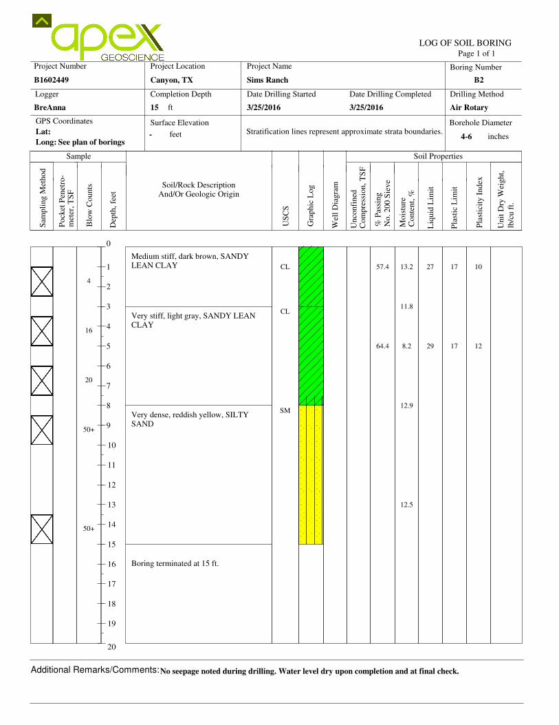
3/25/20163/25/2016 Air Rotary
B1602449
15BreAnna
-
Sims Ranch B2
4-6
Canyon, TX
See plan of borings
No seepage noted during drilling. Water level dry upon completion and at final check.
CL
CL
SM
10
12
13.2
11.8
8.2
12.9
12.5
27
29
17
17
57.4
64.4
4
16
20
50+
50+
Medium stiff, dark brown, SANDYLEAN CLAY
Very stiff, light gray, SANDY LEANCLAY
Very dense, reddish yellow, SILTYSAND
Boring terminated at 15 ft.
Date Drilling Started Date Drilling Completed Drilling Method
US
CS
Gra
phic
Log
Wel
l D
iagra
m
Mois
ture
Page 1 of 1
Completion Depth
Project Location
Logger
GPS Coordinates
Long:
Surface ElevationLat:
Borehole Diameter
feet
% P
assi
ng
No.
200 S
ieve
Pla
stic
Lim
it
Liq
uid
Lim
it
Pla
stic
ity I
ndex
Soil Properties
met
er,
TS
F
Soil/Rock DescriptionAnd/Or Geologic Origin
Sample
LOG OF SOIL BORING
Project Number Project Name Boring Number
Com
pre
ssio
n,
TS
FU
nco
nfi
ned
Conte
nt,
%
lb/c
u f
t.
Unit
Dry
Wei
ght,
inchesStratification lines represent approximate strata boundaries.
ft
Sam
pli
ng M
ethod
Pock
et P
enet
ro-
Blo
w C
ounts
Dep
th,
feet
Additional Remarks/Comments:
0
1
2
3
4
5
6
7
8
9
10
11
12
13
14
15
16
17
18
19
20
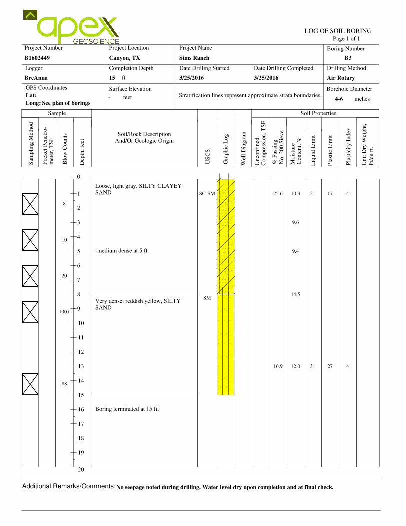
3/25/20163/25/2016 Air Rotary
B1602449
15BreAnna
-
Sims Ranch B3
4-6
Canyon, TX
See plan of borings
No seepage noted during drilling. Water level dry upon completion and at final check.
SC-SM
SM
4
4
10.3
9.6
9.4
14.5
12.0
21
31
17
27
25.6
16.9
8
10
20
100+
88
Loose, light gray, SILTY CLAYEYSAND
-medium dense at 5 ft.
Very dense, reddish yellow, SILTYSAND
Boring terminated at 15 ft.
Date Drilling Started Date Drilling Completed Drilling Method
US
CS
Gra
phic
Log
Wel
l D
iagra
m
Mois
ture
Page 1 of 1
Completion Depth
Project Location
Logger
GPS Coordinates
Long:
Surface ElevationLat:
Borehole Diameter
feet
% P
assi
ng
No.
200 S
ieve
Pla
stic
Lim
it
Liq
uid
Lim
it
Pla
stic
ity I
ndex
Soil Properties
met
er,
TS
F
Soil/Rock DescriptionAnd/Or Geologic Origin
Sample
LOG OF SOIL BORING
Project Number Project Name Boring Number
Com
pre
ssio
n,
TS
FU
nco
nfi
ned
Conte
nt,
%
lb/c
u f
t.
Unit
Dry
Wei
ght,
inchesStratification lines represent approximate strata boundaries.
ft
Sam
pli
ng M
ethod
Pock
et P
enet
ro-
Blo
w C
ounts
Dep
th,
feet
Additional Remarks/Comments:
0
1
2
3
4
5
6
7
8
9
10
11
12
13
14
15
16
17
18
19
20
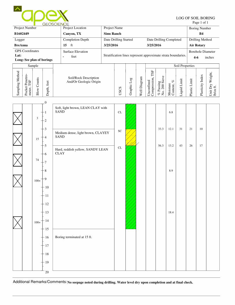
3/25/20163/25/2016 Air Rotary
B1602449
15BreAnna
-
Sims Ranch B4
4-6
Canyon, TX
See plan of borings
No seepage noted during drilling. Water level dry upon completion and at final check.
CL
SC
CL
10
17
6.8
12.1
13.2
8.9
18.4
31
43
21
26
33.3
56.3
3
15
74
100+
100+
Soft, light brown, LEAN CLAY withSAND
Medium dense, light brown, CLAYEYSAND
Hard, reddish yellow, SANDY LEANCLAY
Boring terminated at 15 ft.