Embed Size (px)
Citation preview
GEOTECHNICAL ENGINEERING STUDY
FOR THE
ELLIOTT RESIDENTIAL STRUCTURE PROJECT (Lot 154 Aldasoro Ranch)
Telluride, Colorado
October 6, 2017
Prepared For: Mr. Steve Morton
Morton Architects, Inc. Project Number: 54860GE
PN: 54860GE October 6, 2017
1
1.0 REPORT INTRODUCTION ................................................................................................... 2 1.1 Scope of Project ................................................................................................................... 3
2.0 GEOTECHNICAL ENGINIEERING STUDY ....................................................................... 3 2.1 Geotechnical Engineering Study Scope of Service ............................................................. 3
3.0 FIELD STUDY ........................................................................................................................ 5 3.1 Project location .................................................................................................................... 5 3.2 Site Description and Geomorphology ................................................................................... 6 3.3 Subsurface Soil and Water Conditions ................................................................................ 7
4.0 LABORATORY STUDY ........................................................................................................ 8 5.0 CURSORY SLOPE STABILITY ANALYSES .................................................................... 10 6.0 FOUNDATION RECOMMENDATIONS ............................................................................ 16
6.1 Spread Footings ................................................................................................................. 16 7.0 RETAINING STRUCTURES ............................................................................................... 20 8.0 SUBSURFACE DRAIN SYSTEM ........................................................................................ 22 9.0 CONCRETE FLATWORK .................................................................................................... 24
9.1 Interior Concrete Slab-on-Grade Floors ............................................................................. 24 9.2 Exterior Concrete Flatwork Considerations ........................................................................ 25 9.3 General Concrete Flatwork Comments .............................................................................. 25
10.0 CONSTRUCTION CONSIDERATIONS ............................................................................ 26 10.1 Fill Placement Recommendations..................................................................................... 26
10.1.1 Embankment Fill on Slopes ....................................................................................... 27 10.1.2 Natural Soil Fill......................................................................................................... 28 10.1.3 Granular Compacted Structural Fill ........................................................................... 29
10.2 Excavation Considerations................................................................................................ 29 10.2.1 Excavation Cut Slopes ............................................................................................... 30
10.3 Utility Considerations ....................................................................................................... 30 10.4 Exterior Grading and Drainage Comments....................................................................... 30 10.5 Landscaping Considerations ............................................................................................. 31 10.6 Soil Sulfate Content, Corrosion Issues ............................................................................. 33 10.7 Radon Issues ..................................................................................................................... 33
11.0 CONSTRUCTION MONITORING AND TESTING......................................................... 33 12.0 CONCLUSIONS AND CONSIDERATIONS .................................................................... 34

PN: 54860GE October 6, 2017
2
1.0 REPORT INTRODUCTION This report presents our geotechnical engineering recommendations for the proposed Elliott (Lot 154 Aldasoro) Residential Structure Project. This report was requested by Mr. Steve Morton, Morton Architects, Inc. The field study was completed on September 6, 2017. The laboratory study was completed on October 3, 2017. Geotechnical engineering is a discipline which provides insight into natural conditions and site characteristics such as; subsurface soil and water conditions, soil strength, swell (expansion) potential, consolidation (settlement) potential, and often slope stability considerations. Typically, the information provided by the geotechnical engineer is utilized by many people including the project owner, architect or designer, structural engineer, civil engineer, the project builder and others. The information is used to help develop a design and subsequently implement construction strategies that are appropriate for the subsurface soil and water conditions, and slope stability considerations. It is important that the geotechnical engineer be consulted throughout the design and construction process to verify the implementation of the geotechnical engineering recommendations provided in this report. Generally, the recommendations and technical aspects of this report are intended for design and construction personnel who are familiar with construction concepts and techniques, and understand the terminology presented below. The geotechnical engineering report is the beginning of a process involving the geotechnical engineering consultant on any project. It is common for unforeseen, or otherwise variable subsurface soil and water conditions to be encountered during construction. As discussed in our proposal for our services, it is imperative that we be contacted during the foundation excavation stage of the project to verify that the conditions encountered in our field exploration were representative of those encountered during construction. Compaction testing of fill material and testing of foundation concrete are equally important tasks that should be performed by the geotechnical engineering consultant during construction. We should be contacted during the construction phase of the project and if any questions or comments arise as a result of the information presented below. The following outline provides a synopsis of the various portions of this report;
Sections 1.0 and 2.0 provide an introduction and an establishment of our scope of service.
Sections 3.0 and 4.0 of this report present our geotechnical engineering field and laboratory studies
Sections 5.0 through 9.0 presents our geotechnical engineering design parameters and recommendations which are based on our engineering analysis of the data obtained.
Section 10.0 provides a brief discussion of construction sequencing and strategies which may influence the geotechnical engineering characteristics of the site.
PN: 54860GE October 6, 2017
3
The discussion and construction recommendations presented in Section 10.0 are intended to help develop site soil conditions that are consistent with the geotechnical engineering recommendations presented previously in the report. Ancillary information such as some background information regarding soil corrosion and radon considerations is presented as general reference. The construction considerations section is not intended to address all of the construction planning and needs for the project site, but is intended to provide an overview to aid the owner, design team, and contractor in understanding some construction concepts that may influence some of the geotechnical engineering aspects of the site and proposed development. The data used to generate our recommendations are presented throughout this report and in the attached figures. 1.1 Scope of Project
We understand that the proposed project will consist of designing and constructing a single family residential structure that is supported by a steel reinforced concrete foundation system. A walk-out style basement is proposed with the structure. We anticipate that the lower level floor system, or at least portions of the structure floor system, will consist of concrete slab-on-grade. 2.0 GEOTECHNICAL ENGINIEERING STUDY Our services include a geotechnical engineering study of the subsurface soil and water conditions for development of this site for single family residential use. 2.1 Geotechnical Engineering Study Scope of Service The scope of our study which was delineated in our proposal for services, and the order of presentation of the information within this report, is outlined below. Field Study
• We advanced three (3) test borings at the project within the areas we understand are planned for construction of the proposed structure.
• Select driven sleeve and bulk soil samples were obtained from the test borings and
returned to our laboratory for testing.
Laboratory Study

PN: 54860GE October 6, 2017
4
• The laboratory testing and analysis of the samples obtained included;
Moisture content and dry density, Estimates of soil strength parameters based on laboratory test data, including
direct shear strength tests, to help establish a basis for development of soil bearing capacity and lateral earth pressure values, and soil strength data for our cursory slope stability modeling,
Swell/consolidation tests to help assess the expansion and consolidation potential of the support soils on this site to help estimate potential uplift associated with expansive soils and to help estimate settlement of the foundation system,
Plastic and liquid limit tests to determine the Plasticity Index of the soil, and, Sieve analysis tests.
Geotechnical Engineering Recommendations
• This report addresses the geotechnical engineering aspects of the site and provides recommendations including;
Geotechnical Engineering Section(s)
Subsurface soil and water conditions that may influence the project design
and construction considerations. Geotechnical engineering design parameters including; Viable foundation system concepts including soil bearing capacity
values, settlement considerations for the foundation system concepts that are
viable for this project, and, Lateral Earth Pressure values for design of retaining structures.
Soil support considerations for interior and exterior concrete flatwork. A cursory evaluation of the existing and post-construction slope stability
considerations.
Construction Consideration Section
Fill placement considerations including cursory comments regarding site preparation and grubbing operations,
Comments for placement and compaction of fill on sloped areas, Considerations for excavation cut slopes, Natural soil preparation considerations for use as backfill on the site,
PN: 54860GE October 6, 2017
5
Compaction recommendations for various types of backfill proposed at the site,
Utility trench comments, and, Cursory exterior grading considerations.
• This report provides design parameters, but does not provide foundation design or
design of structure components. The project architect, designer, structural engineer or builder may be contacted to provide a design based on the information presented in this report.
• Our subsurface exploration, laboratory study and engineering analysis do not address
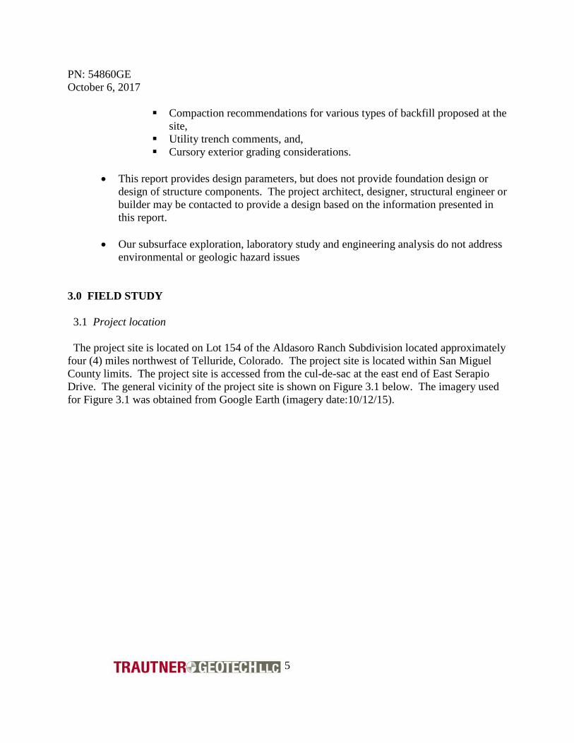
environmental or geologic hazard issues 3.0 FIELD STUDY 3.1 Project location The project site is located on Lot 154 of the Aldasoro Ranch Subdivision located approximately four (4) miles northwest of Telluride, Colorado. The project site is located within San Miguel County limits. The project site is accessed from the cul-de-sac at the east end of East Serapio Drive. The general vicinity of the project site is shown on Figure 3.1 below. The imagery used for Figure 3.1 was obtained from Google Earth (imagery date:10/12/15).

PN: 54860GE October 6, 2017
6
Figure 3.1: Project Vicinity 3.2 Site Description and Geomorphology As discussed above, the project site is accessed from the cul-de-sac located at the east end of East Serapio Drive. The cul-de-sac is constructed over about four (4) feet of embankment fill material above the project lot. The ground surface on the northern portion of the lot is relatively flat. The central area of the lot in areas below and/or immediately adjacent to the southern side of the proposed structure location, slope down to the south-southwest with slope inclinations ranging from about four to one (4:1, horizontal to vertical) to three to one (3:1, h:v). Steeper slopes exist below and to the south of the proposed structure location with slope inclinations in the range of about two to one (2:1, h:v). The site topography presented in Figure 3.3 below may be used to help clarify the topographic conditions of the project lot. Vegetation on the lot consists of dense grass and aspen trees. The geomorphology in the vicinity of the project site is mapped as glacial deposits overlying the Mancos Shale Formation. The glacial deposits encountered consist of variable quantities of gravel and cobble size particles with a sandy silt/clay soil matrix. The glacial soil deposits typically exhibit a low to moderate swell potential when wetted. The Mancos Shale Formation,
Approximate Project Location

PN: 54860GE October 6, 2017
7
and soils derived from the weathering process of the Mancos Shale Formation, often exhibit a moderate to high swell potential when wetted. 3.3 Subsurface Soil and Water Conditions We advanced three (3) test borings in the vicinity of the proposed structure. The corners of the structure had been marked prior to our field study. The approximate locations of our test borings are shown on Figure 3.3 below. The site plan that was used for Figure 3.3 was provided to us by Morton Architects. The logs of the soils encountered in our test borings are presented in Appendix A. Figure 3.3: Approximate Test Boring Locations
TB-1
TB-2 TB-3
PN: 54860GE October 6, 2017
8
The approximate test boring locations shown on the figure above were prepared using notes taken during the field work and are intended to show the approximate test boring locations for reference purposes only. Generally, we encountered sandy silt and clay soils with organic matter from the ground surface to depths ranging from about one (1) to two (2) feet below the ground surface elevation. At depths ranging from one (1) to two (2) feet below the ground surface elevation we encountered a mixture of dense and moist slightly sandy clay and gravels with variable quantities of cobble size aggregates. The test borings were advanced to depths ranging from about eight (8) to twenty (20) feet below the ground surface elevation. The subsurface materials encountered and tested exhibit a relatively low swell potential when wetted, and moderate to high consolidation potential when exposed to typical foundation bearing pressures. We did not encounter free subsurface water in our test borings at the time of the advancement of our test borings at the project site. We suspect that the subsurface water elevation and soil moisture conditions will be influenced by snow melt and/or precipitation and local post construction landscape irrigation. The logs of the subsurface soil conditions encountered in our test borings are presented in Appendix A. The logs present our interpretation of the subsurface conditions encountered exposed in the test borings at the time of our field work. Subsurface soil and water conditions are often variable across relatively short distances. It is likely that variable subsurface soil and water conditions will be encountered during construction. Laboratory soil classifications of samples obtained may differ from field classifications. 4.0 LABORATORY STUDY The laboratory study included tests to estimate the strength, swell and consolidation potential of the soils tested. We performed the following tests on select samples obtained from the test borings. Moisture content and dry density; the moisture content and in-situ dry density of some of the soil samples were assessed in general accordance with ASTM D2216 Atterberg Limits; the plastic limit, liquid limit and plasticity index of some of the soil samples was determined in general accordance with ASTM D4318.

PN: 54860GE October 6, 2017
9
Sieve Analysis Tests; We performed sieve analysis tests on select samples of soil in general accordance with ASTM D422 and/or ASTM C136, depending upon the nature of the materials sampled and tested. The primary use of the sieve analysis test, in conjunction with the Atterberg Limits is for classification and characterization of the materials tested. Based on the results of sieve analysis and Atterberg Limits, the shallow soils encountered in our test borings to a depth of about three (3) feet below the ground surface elevation classify as USCS type “SM” silty sand with gravel. The subsurface materials below a depth of about three (3) feet below the ground surface elevation are more granular, more closely resembling a USCS type “GC” or “GM” silty gravel with sand. The results of the sieve analysis and Atterberg Limits test performed are presented on Figure 4.1 of Appendix B. Direct Shear Strength tests; Direct shear strength tests were performed on select soil samples to estimate the soil strength characteristics in general accordance with ASTM D3080. We obtained an angle of internal friction (phi) of about 19 degrees and a cohesion of about 365 pounds per square foot in our analysis. This data is based on the soil materials that pass the #10 sieve screen, and is representative of the matrix of the overall soil mass. Based on the quantity of gravel and cobbles that we encountered in our test borings we have used an estimated angle of internal friction of 25 degrees and cohesion of about 200 pounds per square foot for the strength data that represents the overall soil mass properties. The results of the direct shear strength tests are presented on Figure 4.2 of Appendix B. Swell-Consolidation Tests; the one dimensional swell-consolidation potential of some of the soil samples obtained was determined in general accordance with ASTM D2435. The soil sample tested is exposed to varying loads and usually the addition of water. The one-dimensional swell-consolidation response of the soil sample to the loads and/or water is represented graphically on Figures 4.3 and 4.4 A synopsis of some of our laboratory data for some of the samples tested is tabulated below.
Sample Designation
Moisture Content (percent)
Dry Density (PCF)
Measured Swell
Pressure* (PSF)
Graphical Load Back
Swell Pressure
(PSF)
Swell Potential
(% under 100 psf load)
TB-1 @ 8 feet 7.3 120.8 840
900
0.9
TB-3 @ 3 feet 7.7 107.6 620 500 0.2 *NOTE: We determine the swell pressure as measured in our laboratory using the constant volume method. The graphically determined swell pressure may be different from that measured in the laboratory.
PN: 54860GE October 6, 2017
10
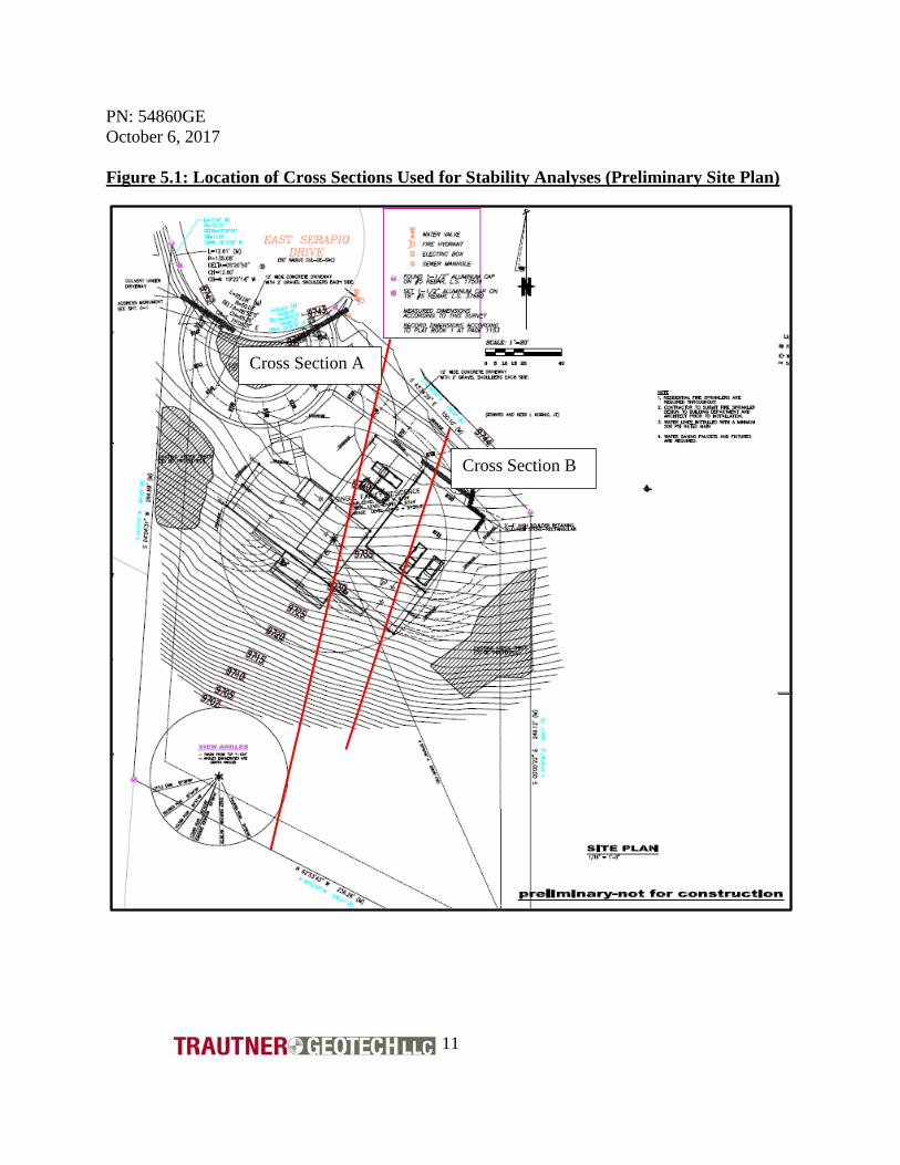
5.0 CURSORY SLOPE STABILITY ANALYSES This section of the report provides global/local slope stability analyses for the slope surface on and below the proposed structure site. The analyses presented below are based on the topography/geometry indicated on the preliminary project plans. We did not encounter subsurface free water in our test borings at the time of our field study. Due to the typical heavy snowfall accumulation for the area we feel that there is the potential for water to access the subsurface soils. The project must be designed with this in mind. Water must not be allowed to pool on the ground surface of the lot, particularly above retaining structures or unrestrained cut or fill slopes. Exterior backfill must be well compacted to ensure that surface water does not readily access the subsurface slope mass. Collected water, such as water obtained from roof gutters or concrete flatwork such as driveways must be directed to areas away from the structure, project retaining walls, and downslope areas immediately below these structures or project retaining walls. Subsurface free water must be allowed to drain from the excavation cut slope surfaces or from behind retaining wall structures. Accumulation of subsurface free water in the slopes of the project lot will greatly reduce the long-term stability of the project lot and/or structure(s). We suspect that the subsurface drain systems adjacent to the structure retaining walls will flow water in some locations during certain times of the year. Our slope stability analyses include an assessment of the existing (preconstruction) slope stability conditions, and post construction stability conditions based on the current location of the structure and anticipated finished floor/bearing elevations for the structure and structure access driveway. The slope surface cross sections analyzed are based on the available topographic data that has been provided to us. We estimated the topographic conditions below the available topography on the south end of the project lot. The cross sections shown on Figure 5.1 below were used as a basis for the slope surface geometry used in our analyses.
PN: 54860GE October 6, 2017
11
Figure 5.1: Location of Cross Sections Used for Stability Analyses (Preliminary Site Plan)
Cross Section A
Cross Section B
PN: 54860GE October 6, 2017
12
There are numerous methods and techniques available for slope stability analysis. Most methods include an evaluation of;
• the strength of the soil materials and/or formational materials within the slope, • anisotropies within the slope materials, such as formational material bedding planes, and
anomalous soil contacts, • the subsurface water and soil moisture conditions, and, • the pre-construction and post-construction geometry of the slope areas where
development and construction is proposed. The data developed during the analysis is condensed and used to estimate the forces within a soil mass that tend to drive movement and the forces that tend to resist movement. The ratio of resisting forces to driving forces is often referred to as the “theoretical slope factor of safety” (FOS) which is a somewhat misleading term to describe this ratio. The ratio is not a true factor of safety, but is a useful mathematical characterization of the forces within a soil mass and the associated stability condition of the slope being analyzed. A ratio of less than one (1) indicates that the driving forces within a soil mass are greater than the resisting forces, therefore movement of the slope is occurring. A ratio of one (1) indicates that the driving forces are equal to the resisting forces, which indicates that movement within the soil can be triggered by only slight increases in the driving forces or slight reductions in the resisting forces. A ratio of greater than one (1) is an indication that the driving forces are less than the resisting forces and the slope is not moving. Since there are numerous variables and incongruities within most soil masses, a slope is generally not considered as stable unless the ratio is about 1.5 or greater. Generally, slopes or slope/structure combinations with a theoretical factor of safety that is greater than 1.5 are considered appropriate for sites where structures are planned. Temporary excavation cut slopes that exhibit a factor of safety of about 1.3 are often considered as being stable for temporary applications, and for some roadway applications. We used SLIDE 7.0 slope stability software to evaluate the stability of computer modeled slope cross sections of select portions of this site. We primarily used the Modified Bishop’s Method of slices to analyze the computer modeled slopes. The Modified Bishop’s Method of Slices evaluates the resisting and driving forces within slices of the sloped soil mass along a theoretical semi-circular failure plane. The semicircular failure plane with the lowest theoretical factor of safety is labeled the critical circle. We have used a single soil region for the analyses presented below. This region represents the properties obtained for the granular soil materials encountered in our test borings. We have utilized and angle of internal friction (phi) of twenty-five (25) degrees and a cohesive value of two-hundred (200) pounds per square foot in our analyses. A moist soil density of 125 pounds per square foot was also used in our analyses.

PN: 54860GE October 6, 2017
13
The analysis shown on Figure 5.2 below indicates the theoretical factor of safety for the existing (preconstruction) slope conditions of the project lot along Cross Section A. We obtained a theoretical factor of safety in the range of about 1.62 for the global stability of the project site which may be considered as stable. Figure 5.2: Theoretical F.O.S. for the Global Stability of the Existing Slope Conditions (Cross Section A), FOS=1.62
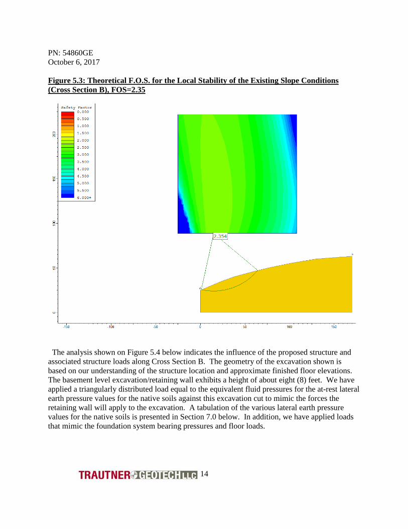
The analysis shown on Figure 5.3 below indicates the existing slope stability characteristics local to the proposed structure location along Cross Section B. We obtained a theoretical factor of safety of about 2.5 which may be considered as being stable.
PN: 54860GE October 6, 2017
14
Figure 5.3: Theoretical F.O.S. for the Local Stability of the Existing Slope Conditions (Cross Section B), FOS=2.35
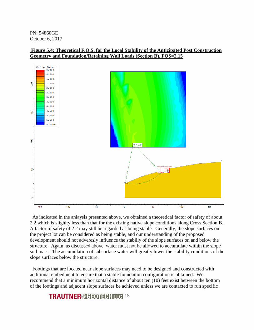
The analysis shown on Figure 5.4 below indicates the influence of the proposed structure and associated structure loads along Cross Section B. The geometry of the excavation shown is based on our understanding of the structure location and approximate finished floor elevations. The basement level excavation/retaining wall exhibits a height of about eight (8) feet. We have applied a triangularly distributed load equal to the equivalent fluid pressures for the at-rest lateral earth pressure values for the native soils against this excavation cut to mimic the forces the retaining wall will apply to the excavation. A tabulation of the various lateral earth pressure values for the native soils is presented in Section 7.0 below. In addition, we have applied loads that mimic the foundation system bearing pressures and floor loads.
PN: 54860GE October 6, 2017
15
Figure 5.4: Theoretical F.O.S. for the Local Stability of the Anticipated Post Construction Geometry and Foundation/Retaining Wall Loads (Section B), FOS=2.15
As indicated in the anlaysis presented above, we obtained a theoretical factor of safety of about 2.2 which is slighlty less than that for the existing native slope conditions along Cross Section B. A factor of safety of 2.2 may still be regarded as being stable. Generally, the slope surfaces on the project lot can be considered as being stable, and our understanding of the proposed development should not adveresly influence the stabiliy of the slope surfaces on and below the structure. Again, as discussed above, water must not be allowed to accumulate within the slope soil mass. The accumulation of subsurface water will greatly lower the stability conditions of the slope surfaces below the structure. Footings that are located near slope surfaces may need to be designed and constructed with additional embedment to ensure that a stable foundaiton configuration is obtained. We recommend that a minimum horizontal distance of about ten (10) feet exist between the bottom of the footings and adjacent slope surfaces be achieved unless we are contacted to run specific
PN: 54860GE October 6, 2017
16
stability analyses. We are available to provide more detailed slope stability analyses, including localized footing stability for footings that are located near sloped surfaces as the project design progresses. 6.0 FOUNDATION RECOMMENDATIONS The proposed structure may be supported by a conventional spread footing foundation system based on the subsurface conditions that were encountered in our test borings, the laboratory test data, and on our understanding of the project. Our recommendations for a spread footing foundation system are provided in Section 5.1 below. We are available to provide recommendations for alternative foundation systems at your request. The integrity and long-term performance of any type of foundation system is influenced by the quality of workmanship which is implemented during construction. It is imperative that all excavation and fill placement operations be conducted by qualified personnel using appropriate equipment and techniques to provide suitable support conditions for the foundation system. 6.1 Spread Footings The soil samples tested from the anticipated support elevations in our test borings exhibited a low to moderate swell potential when wetted, and moderate to high consolidation potential when exposed to typical foundation bearing pressures. The performance of spread footings on this project site will be primarily influenced by potential for settlement rather than movement from swelling soil conditions. We recommend that the footings be supported by a layer of moisture conditioned and compacted natural soil which is overlain by a layer of compacted structural fill material. This concept is outlined below;
• The foundation excavation should be excavated to at least one (1) foot below the proposed footing support elevation.
• The natural soils exposed in the bottom of the excavation should be scarified to a depth of about six (6) to eight (8) inches
• The scarified soil should be thoroughly moisture conditioned to about two (2) percent above the laboratory determined optimum moisture content and then compacted.
• After completion of the compaction of the moisture conditioned natural soil a minimum one (1) foot thick layer of granular aggregate base course structural fill material should be placed, moisture conditioned and compacted.
• Additional depths of structural fill may be needed for some footings, particularly isolated footings, to help decrease potential post construction settlement of the footings and help decrease differential settlement across the structure foundation system. We have
PN: 54860GE October 6, 2017
17
tabulated anticipated magnitudes of settlement versus supporting structure fill depths for both continuous and isolated spread footings below.
• The moisture conditioned natural soil material and the granular soils should be compacted as discussed under the Compaction Recommendations portion of this report, below.
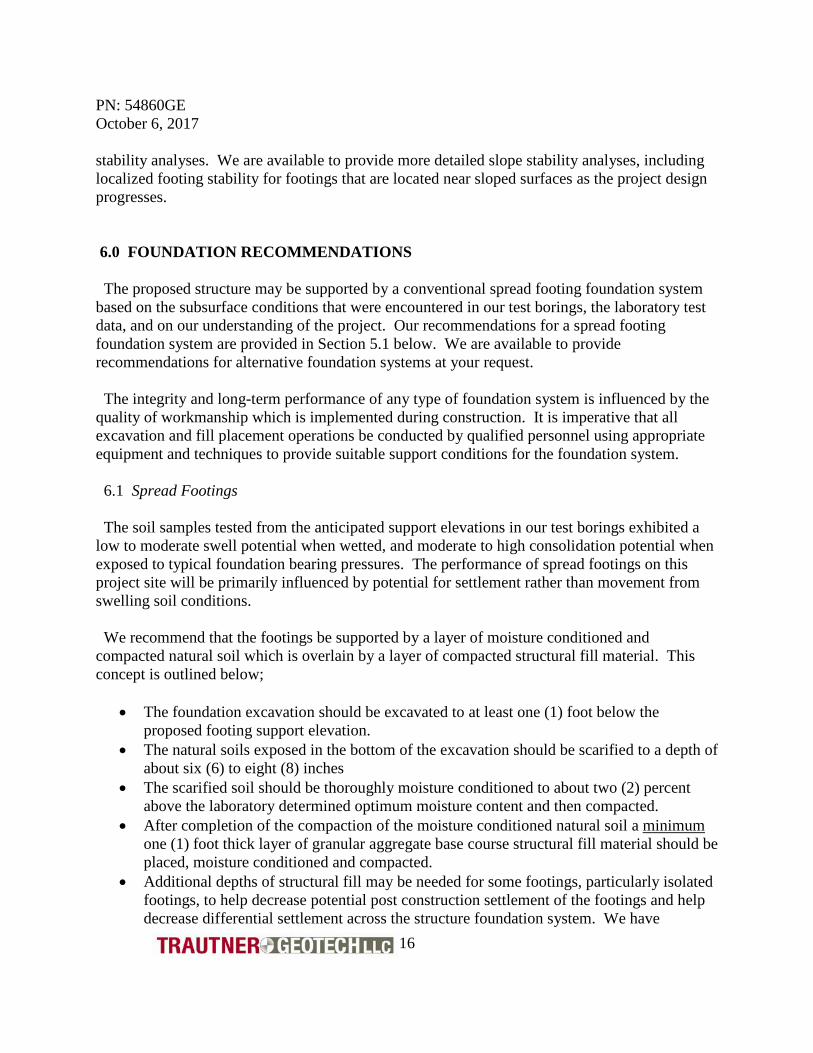
The footing embedment is a relatively critical, yet often overlooked, aspect of foundation construction. The embedment helps develop the soil bearing capacity, increases resistance of the footing to lateral movement and decreases the potential for rapid moisture changes in the footing support soils, particularly in crawl space areas. All footings should have a minimum depth of embedment of at least one (1) foot. The embedment concept is shown below.
Spread footings located away from sloped areas may be designed using the bearing capacity information tabulated below. As discussed above, it may be necessary to extend the bearing elevation of footings that are located directly adjacent to sloped areas to ensure that a stable footing configuration is obtained.
Minimum depth of embedment Footing
Footing Embedment Concept No Scale
PN: 54860GE October 6, 2017
18
Minimum Depth of Embedment (Feet)
Continuous Footing Design Capacity (psf)
Isolated Footing Design Capacity (psf)
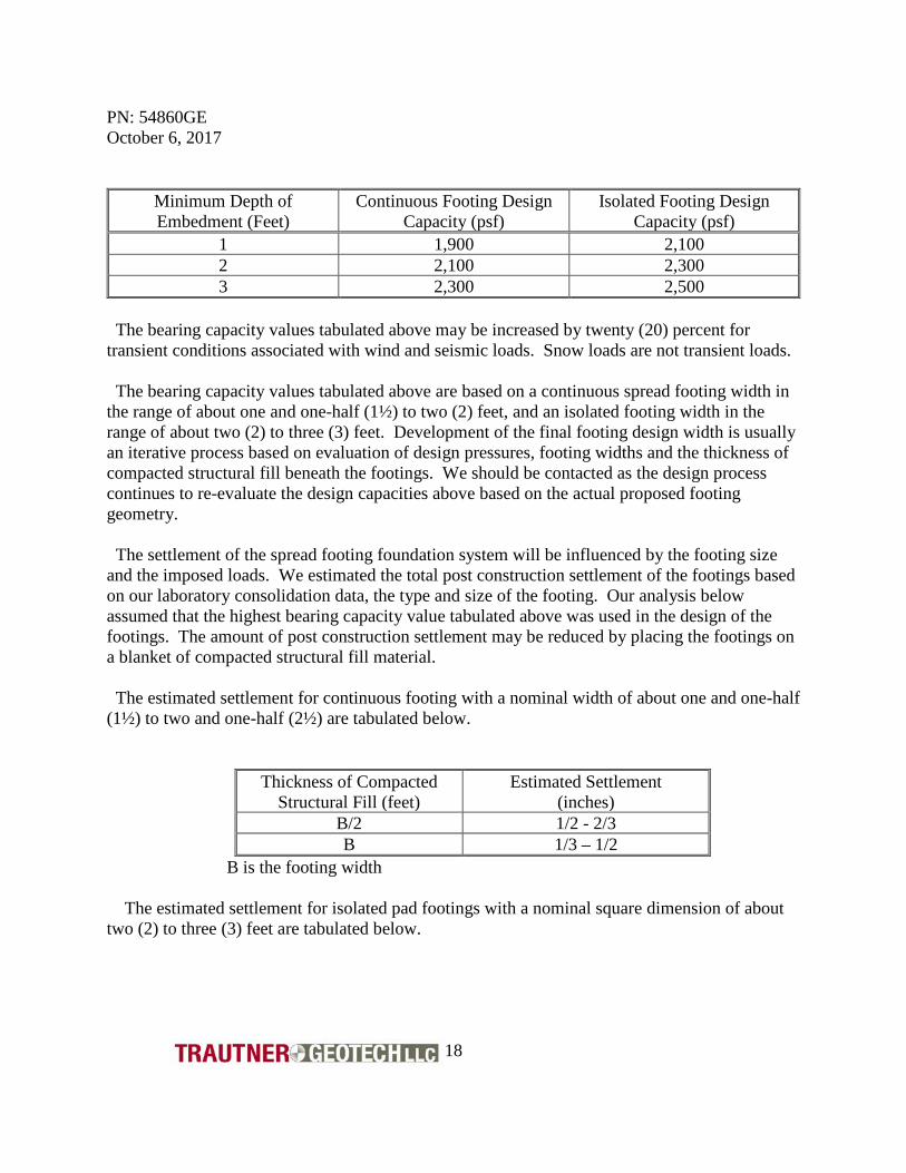
1 1,900 2,100 2 2,100 2,300 3 2,300 2,500
The bearing capacity values tabulated above may be increased by twenty (20) percent for transient conditions associated with wind and seismic loads. Snow loads are not transient loads. The bearing capacity values tabulated above are based on a continuous spread footing width in the range of about one and one-half (1½) to two (2) feet, and an isolated footing width in the range of about two (2) to three (3) feet. Development of the final footing design width is usually an iterative process based on evaluation of design pressures, footing widths and the thickness of compacted structural fill beneath the footings. We should be contacted as the design process continues to re-evaluate the design capacities above based on the actual proposed footing geometry. The settlement of the spread footing foundation system will be influenced by the footing size and the imposed loads. We estimated the total post construction settlement of the footings based on our laboratory consolidation data, the type and size of the footing. Our analysis below assumed that the highest bearing capacity value tabulated above was used in the design of the footings. The amount of post construction settlement may be reduced by placing the footings on a blanket of compacted structural fill material. The estimated settlement for continuous footing with a nominal width of about one and one-half (1½) to two and one-half (2½) are tabulated below.
Thickness of Compacted Structural Fill (feet)
Estimated Settlement (inches)
B/2 1/2 - 2/3 B 1/3 – 1/2
B is the footing width The estimated settlement for isolated pad footings with a nominal square dimension of about two (2) to three (3) feet are tabulated below.
PN: 54860GE October 6, 2017
19
Thickness of Compacted
Structural Fill (feet) Estimated Settlement
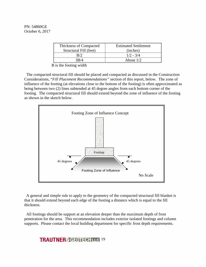
(inches) B/2 1/2 - 3/4 3B/4 About 1/2
B is the footing width The compacted structural fill should be placed and compacted as discussed in the Construction Considerations, “Fill Placement Recommendations” section of this report, below. The zone of influence of the footing (at elevations close to the bottom of the footing) is often approximated as being between two (2) lines subtended at 45 degree angles from each bottom corner of the footing. The compacted structural fill should extend beyond the zone of influence of the footing as shown in the sketch below. A general and simple rule to apply to the geometry of the compacted structural fill blanket is that it should extend beyond each edge of the footing a distance which is equal to the fill thickness. All footings should be support at an elevation deeper than the maximum depth of frost penetration for the area. This recommendation includes exterior isolated footings and column supports. Please contact the local building department for specific frost depth requirements.
45 degrees 45 degrees
Footing
No Scale
Footing Zone of Influence Concept
Footing Zone of Influence
PN: 54860GE October 6, 2017
20
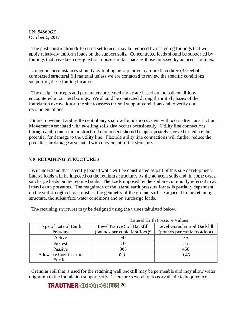
The post construction differential settlement may be reduced by designing footings that will apply relatively uniform loads on the support soils. Concentrated loads should be supported by footings that have been designed to impose similar loads as those imposed by adjacent footings. Under no circumstances should any footing be supported by more than three (3) feet of compacted structural fill material unless we are contacted to review the specific conditions supporting these footing locations. The design concepts and parameters presented above are based on the soil conditions encountered in our test borings. We should be contacted during the initial phases of the foundation excavation at the site to assess the soil support conditions and to verify our recommendations. Some movement and settlement of any shallow foundation system will occur after construction. Movement associated with swelling soils also occurs occasionally. Utility line connections through and foundation or structural component should be appropriately sleeved to reduce the potential for damage to the utility line. Flexible utility line connections will further reduce the potential for damage associated with movement of the structure. 7.0 RETAINING STRUCTURES We understand that laterally loaded walls will be constructed as part of this site development. Lateral loads will be imposed on the retaining structures by the adjacent soils and, in some cases, surcharge loads on the retained soils. The loads imposed by the soil are commonly referred to as lateral earth pressures. The magnitude of the lateral earth pressure forces is partially dependent on the soil strength characteristics, the geometry of the ground surface adjacent to the retaining structure, the subsurface water conditions and on surcharge loads. The retaining structures may be designed using the values tabulated below. Lateral Earth Pressure Values
Type of Lateral Earth Pressure
Level Native Soil Backfill (pounds per cubic foot/foot)*
Level Granular Soil Backfill (pounds per cubic foot/foot)
Active 50 35 At-rest 70 55 Passive 305 460
Allowable Coefficient of Friction
0.31 0.45
Granular soil that is used for the retaining wall backfill may be permeable and may allow water migration to the foundation support soils. There are several options available to help reduce
PN: 54860GE October 6, 2017
21
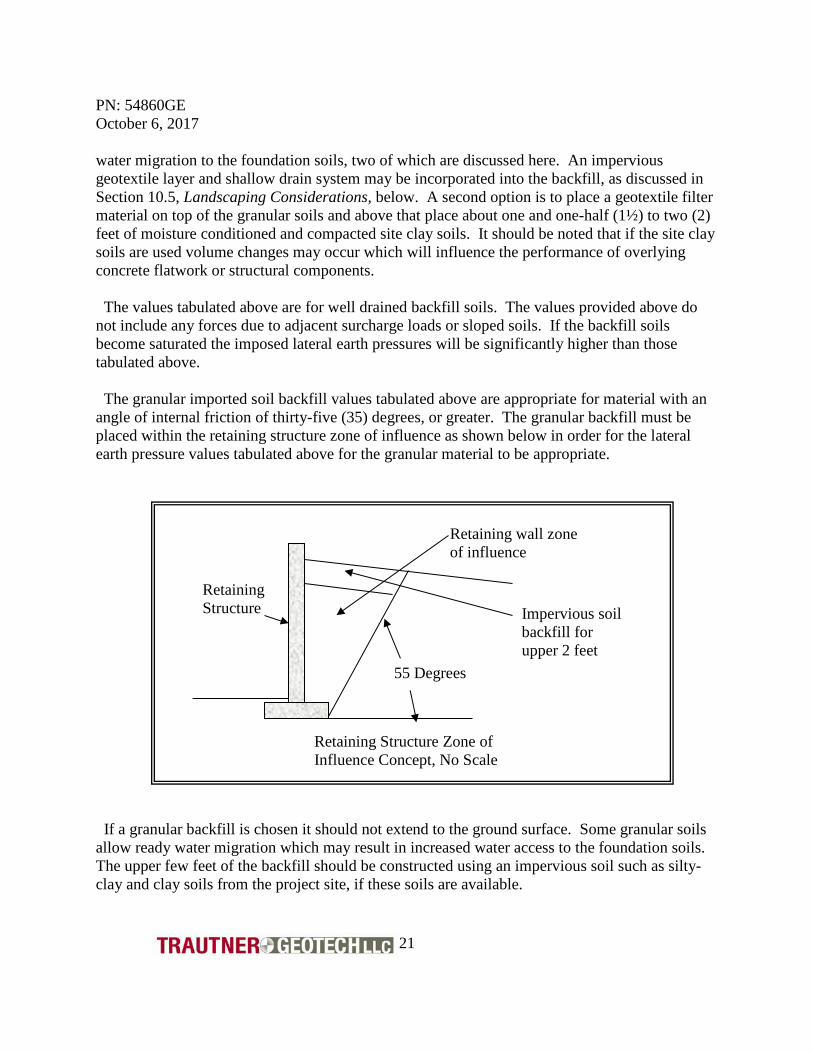
water migration to the foundation soils, two of which are discussed here. An impervious geotextile layer and shallow drain system may be incorporated into the backfill, as discussed in Section 10.5, Landscaping Considerations, below. A second option is to place a geotextile filter material on top of the granular soils and above that place about one and one-half (1½) to two (2) feet of moisture conditioned and compacted site clay soils. It should be noted that if the site clay soils are used volume changes may occur which will influence the performance of overlying concrete flatwork or structural components. The values tabulated above are for well drained backfill soils. The values provided above do not include any forces due to adjacent surcharge loads or sloped soils. If the backfill soils become saturated the imposed lateral earth pressures will be significantly higher than those tabulated above. The granular imported soil backfill values tabulated above are appropriate for material with an angle of internal friction of thirty-five (35) degrees, or greater. The granular backfill must be placed within the retaining structure zone of influence as shown below in order for the lateral earth pressure values tabulated above for the granular material to be appropriate.
If a granular backfill is chosen it should not extend to the ground surface. Some granular soils allow ready water migration which may result in increased water access to the foundation soils. The upper few feet of the backfill should be constructed using an impervious soil such as silty-clay and clay soils from the project site, if these soils are available.
55 Degrees
Retaining wall zone of influence
Retaining Structure
Retaining Structure Zone of Influence Concept, No Scale
Impervious soil backfill for upper 2 feet

PN: 54860GE October 6, 2017
22
Backfill should not be placed and compacted behind the retaining structure unless approved by the project structural engineer. Backfill placed prior to construction of all appropriate structural members such as floors, or prior to appropriate curing of the retaining wall concrete (if used) may result in severe damage and/or failure of the retaining structure.
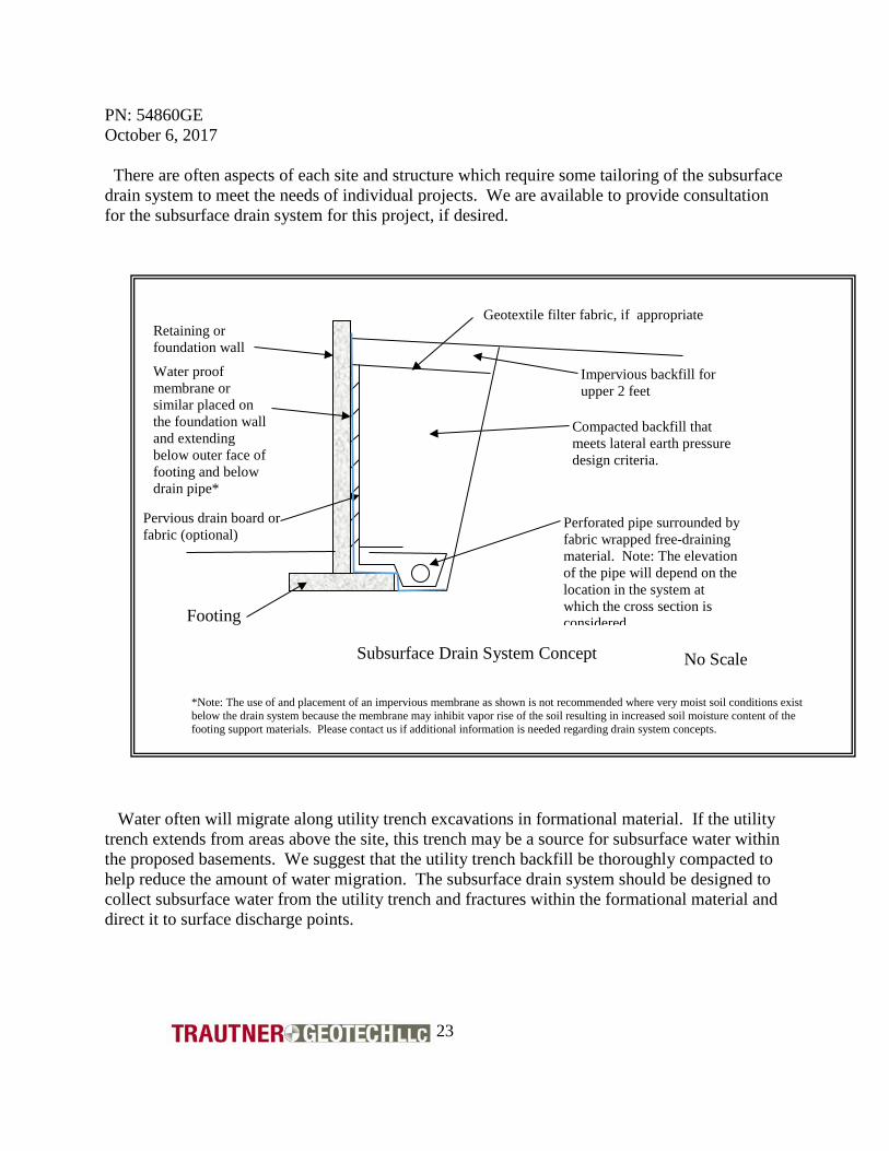
8.0 SUBSURFACE DRAIN SYSTEM A subsurface drain system and/or weep holes should be included in the retaining structure design. Exterior retaining structures may be constructed with weep holes to allow subsurface water migration through the retaining structures. A drain system constructed with a free draining aggregate material and a perforated pipe should be constructed adjacent to interior retaining structures. We suggest that the system consist of a fabric-wrapped aggregate, or a sand material (some sands may not need fabric, we are available to discuss this with you) which surrounds a rigid perforated pipe. We typically do not recommend use of flexible corrugated perforated pipe since it is not readily possible to establish a uniform gradient of the flexible pipe throughout the drain system alignment. Corrugated drain tile is perforated throughout the entire circumference of the pipe and therefore water can escape from the perforations at undesirable locations after being collected. The nature of the perforations of the corrugated material further decreases its effectiveness as a subsurface drain conduit. The drain system pipe should be graded to surface outlets or a sump vault. Typically, a minimum gradient of about two (2) percent is preferred for subsurface drain systems, but site geometry and topography may influence the actual installed pipe gradient. Water must not be allowed to pool along any portion of the subsurface drain system. An improperly constructed subsurface drain system may actually promote water access to undesirable locations. The drain system pipe should be surrounded by about two (2) to four (4) cubic feet per lineal foot of free draining aggregate or sand. If a sump vault and pump are incorporated into the subsurface drain system, care should be taken so that the water pumped from the vault does not recirculate through pervious soils and obtain access to the basement or crawl space areas. A generalized subsurface drain system concept is shown below.
PN: 54860GE October 6, 2017
23
There are often aspects of each site and structure which require some tailoring of the subsurface drain system to meet the needs of individual projects. We are available to provide consultation for the subsurface drain system for this project, if desired.
Water often will migrate along utility trench excavations in formational material. If the utility trench extends from areas above the site, this trench may be a source for subsurface water within the proposed basements. We suggest that the utility trench backfill be thoroughly compacted to help reduce the amount of water migration. The subsurface drain system should be designed to collect subsurface water from the utility trench and fractures within the formational material and direct it to surface discharge points.
Perforated pipe surrounded by fabric wrapped free-draining material. Note: The elevation of the pipe will depend on the location in the system at which the cross section is considered
Impervious backfill for upper 2 feet
Compacted backfill that meets lateral earth pressure design criteria.
Retaining or foundation wall
Water proof membrane or similar placed on the foundation wall and extending below outer face of footing and below drain pipe*
Pervious drain board or fabric (optional)
Footing
Subsurface Drain System Concept No Scale
Geotextile filter fabric, if appropriate
*Note: The use of and placement of an impervious membrane as shown is not recommended where very moist soil conditions exist below the drain system because the membrane may inhibit vapor rise of the soil resulting in increased soil moisture content of the footing support materials. Please contact us if additional information is needed regarding drain system concepts.
PN: 54860GE October 6, 2017
24
9.0 CONCRETE FLATWORK We understand that both interior and exterior concrete flatwork will be included in the project design. Concrete flatwork is typically lightly loaded and has a limited capability to resist shear forces associated with uplift from swelling soils and/or frost heave. It is prudent for the design and construction of concrete flatwork on this project to be able to accommodate some movement associated with swelling soil conditions, if possible. We encountered silt soil materials and organic matter in the upper portions of our test borings. We recommend that silt soils be removed from area that will support concrete flatwork. Organic materials must be removed from areas below the project flatwork. 9.1 Interior Concrete Slab-on-Grade Floors A primary goal in the design and construction of interior concrete slab-on-grade floors is to reduce the amount of post construction uplift associated with swelling soils, or downward movement due to consolidation of soft soils. A parallel goal is to reduce the potential for damage to the structure associated with any movement of the slab-on-grade which may occur. There are limited options available to help mitigate the influence of volume changes in the support soil for concrete slab-on-grade floors, these include;
• Preconstruction scarification, moisture conditioning and re-compaction of the natural soils in areas proposed for support of concrete flatwork, and/or,
• Placement and compaction of granular compacted structural fill material. The only means to completely mitigate the influence of volume changes on the performance of interior floors is to structurally support the floors. Floors that are suspended by the foundation system will not be influenced by volume changes in the site soils. The suggestions and recommendations presented below are intended to help reduce the influence of swelling soils on the performance of the concrete slab-on-grade floors. Interior concrete slab-on-grade floors may be supported by a composite fill blanket which is composed of a six (6) inch thick lower layer of scarified, moisture conditioned natural soil that is overlain by an eight (8) inch thick blanket of compacted structural fill. The scarified fill material and the compacted structural fill material should be constructed as discussed under the Construction Considerations, “Fill Placement Considerations” section of this report below.” Capillary and vapor moisture rise through the slab support soil may provide a source for moisture in the concrete slab-on-grade floor. This moisture may promote development of mold or mildew in poorly ventilated areas and may influence the performance of floor coverings and mastic placed directly on the floor slabs. The type of floor covering, adhesives used, and other considerations that are not related to the geotechnical engineering practice will influence the
PN: 54860GE October 6, 2017
25
design. The architect, builder and particularly the floor covering/adhesive manufacturer should be contacted regarding the appropriate level of protection required for their products. 9.2 Exterior Concrete Flatwork Considerations Exterior concrete flatwork includes concrete driveway slabs, aprons, patios, and walkways. The desired performance of exterior flatwork typically varies depending on the proposed use of the site and each owner’s individual expectations. As with interior flatwork, exterior flatwork is particularly prone to movement and potential damage due to movement of the support soils. This movement and associated damage may be reduced by following the recommendations discussed under interior flatwork, above. Unlike interior flatwork, exterior flatwork may be exposed to frost heave, particularly on sites with high silt-content soils. It may be prudent to remove silt soils from exterior flatwork support areas where movement of exterior flatwork will adversely affect the project, such as near the interface between the driveway and the interior garage floor slab. If silt soils are encountered, they should be removed to the maximum depth of frost penetration for the area where movement of exterior flatwork is undesirable. If some movement of exterior flatwork is acceptable, we suggest that the support areas be prepared by scarification, moisture conditioning and re-compaction of about four (4) inches of the natural soils followed by placement of about four (4) to six (6) inches of compacted granular fill material. The scarified material and granular fill materials should be placed as discussed under the Construction Considerations, “Fill Placement Recommendations” section of this report, below. It is important that exterior flatwork be separated from exterior column supports, masonry veneer, finishes and siding. No support columns, for the structure or exterior decks, should be placed on exterior concrete unless movement of the columns will not adversely affect the supported structural components. Movement of exterior flatwork may cause damage if it is in contact with portions of the structure exterior. Exterior flatwork should not be placed on soils prepared for support of landscaping vegetation. Cultivated soils will not provide suitable support for concrete flatwork. 9.3 General Concrete Flatwork Comments
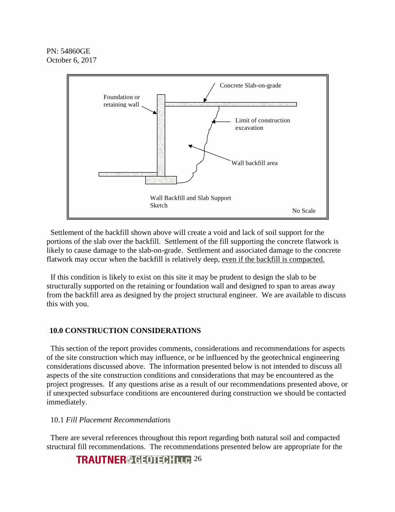
It is relatively common that both interior and exterior concrete flatwork is supported by areas of fill adjacent to either shallow foundation walls or basement retaining walls. A typical sketch of this condition is shown below.
PN: 54860GE October 6, 2017
26
Settlement of the backfill shown above will create a void and lack of soil support for the portions of the slab over the backfill. Settlement of the fill supporting the concrete flatwork is likely to cause damage to the slab-on-grade. Settlement and associated damage to the concrete flatwork may occur when the backfill is relatively deep, even if the backfill is compacted. If this condition is likely to exist on this site it may be prudent to design the slab to be structurally supported on the retaining or foundation wall and designed to span to areas away from the backfill area as designed by the project structural engineer. We are available to discuss this with you. 10.0 CONSTRUCTION CONSIDERATIONS
This section of the report provides comments, considerations and recommendations for aspects of the site construction which may influence, or be influenced by the geotechnical engineering considerations discussed above. The information presented below is not intended to discuss all aspects of the site construction conditions and considerations that may be encountered as the project progresses. If any questions arise as a result of our recommendations presented above, or if unexpected subsurface conditions are encountered during construction we should be contacted immediately. 10.1 Fill Placement Recommendations There are several references throughout this report regarding both natural soil and compacted structural fill recommendations. The recommendations presented below are appropriate for the
Limit of construction excavation
Foundation or retaining wall
Concrete Slab-on-grade
Wall backfill area
Wall Backfill and Slab Support Sketch
No Scale

PN: 54860GE October 6, 2017
27
fill placement considerations discussed throughout the report above. All areas to receive fill, structural components, or other site improvements should be properly prepared and grubbed at the initiation of the project construction. The grubbing operations should include scarification and removal of organic material and soil. No fill material or concrete should be placed in areas where existing vegetation or fill material exist. 10.1.1 Embankment Fill on Slopes Embankment fill placed on slopes must be placed in areas that have been properly prepared prior to placement of the fill material. The fill should be placed in a toe key and benches constructed into the slope. The concept is shown below.
The width of the toe key should be at least one-fourth (1/4) of the height of the fill. The elevation difference between each bench, width, and geometry of each bench is not critical, but generally, the elevation difference between each lift should not exceed about three (3) to four (4) feet. The benches should be of sufficient width to allow for placement of horizontal lifts of fill material, therefore the size of the compaction equipment used will influence the bench widths. Embankment fill material thicker than five (5) feet should be analyzed on a site-specific basis. The fill mass may impose significant loads on, and influence the stability of the underlying slope. We suggest that no fill slopes steeper than two and one-half to one (2½:1, horizontal to
New Embankment Fill
Bench Drain
Toe Key Drain
Benches Toe Key
Pre-construction ground surface
Toe Key and Bench Concept No Scale
PN: 54860GE October 6, 2017
28
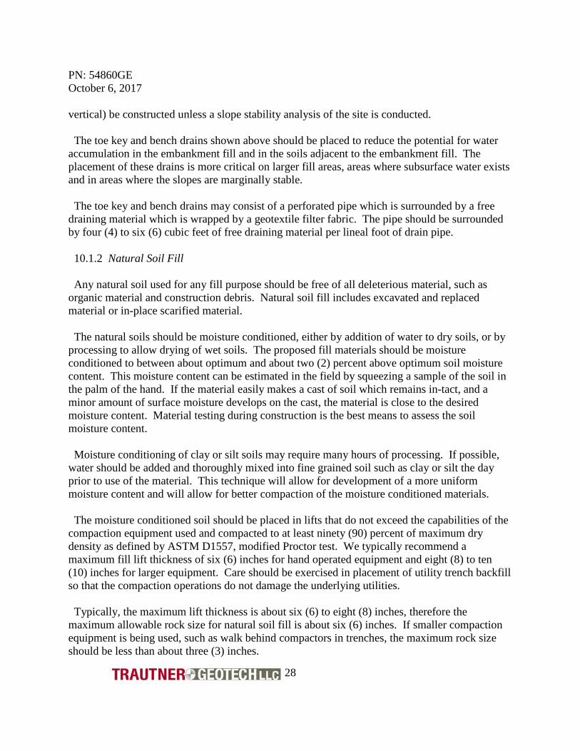
vertical) be constructed unless a slope stability analysis of the site is conducted. The toe key and bench drains shown above should be placed to reduce the potential for water accumulation in the embankment fill and in the soils adjacent to the embankment fill. The placement of these drains is more critical on larger fill areas, areas where subsurface water exists and in areas where the slopes are marginally stable. The toe key and bench drains may consist of a perforated pipe which is surrounded by a free draining material which is wrapped by a geotextile filter fabric. The pipe should be surrounded by four (4) to six (6) cubic feet of free draining material per lineal foot of drain pipe. 10.1.2 Natural Soil Fill Any natural soil used for any fill purpose should be free of all deleterious material, such as organic material and construction debris. Natural soil fill includes excavated and replaced material or in-place scarified material. The natural soils should be moisture conditioned, either by addition of water to dry soils, or by processing to allow drying of wet soils. The proposed fill materials should be moisture conditioned to between about optimum and about two (2) percent above optimum soil moisture content. This moisture content can be estimated in the field by squeezing a sample of the soil in the palm of the hand. If the material easily makes a cast of soil which remains in-tact, and a minor amount of surface moisture develops on the cast, the material is close to the desired moisture content. Material testing during construction is the best means to assess the soil moisture content. Moisture conditioning of clay or silt soils may require many hours of processing. If possible, water should be added and thoroughly mixed into fine grained soil such as clay or silt the day prior to use of the material. This technique will allow for development of a more uniform moisture content and will allow for better compaction of the moisture conditioned materials. The moisture conditioned soil should be placed in lifts that do not exceed the capabilities of the compaction equipment used and compacted to at least ninety (90) percent of maximum dry density as defined by ASTM D1557, modified Proctor test. We typically recommend a maximum fill lift thickness of six (6) inches for hand operated equipment and eight (8) to ten (10) inches for larger equipment. Care should be exercised in placement of utility trench backfill so that the compaction operations do not damage the underlying utilities. Typically, the maximum lift thickness is about six (6) to eight (8) inches, therefore the maximum allowable rock size for natural soil fill is about six (6) inches. If smaller compaction equipment is being used, such as walk behind compactors in trenches, the maximum rock size should be less than about three (3) inches.
PN: 54860GE October 6, 2017
29
10.1.3 Granular Compacted Structural Fill Granular compacted structural fill is referenced in numerous locations throughout the text of this report. Granular compacted structural fill should be constructed using an imported commercially produced rock product such as aggregate road base. Many products other than road base, such as clean aggregate or select crusher fines may be suitable, depending on the intended use. If a specification is needed by the design professional for development of project specifications, a material conforming to the Colorado Department of Transportation (CDOT) “Class 6” aggregate road base material can be specified. This specification can include an option for testing and approval in the event the contractor’s desired material does not conform to the Class 6 aggregate specifications. We have provided the CDOT Specifications for Class 6 material below
Grading of CDOT Class 6 Aggregate Base-Course Material Sieve Size Percent Passing Each Sieve
¾ inch 100 #4 30 – 65 #8 25 – 55
#200 3 – 12 Liquid Limit less than 30 All compacted structural fill should be moisture conditioned and compacted to at least ninety (90) percent of maximum dry density as defined by ASTM D1557, modified Proctor test. Areas where the structural fill will support traffic loads under concrete slabs or asphalt concrete should be compacted to at least ninety-five (95) percent of maximum dry density as defined by ASTM D1557, modified Proctor test. 10.2 Excavation Considerations Unless a specific classification is performed, the site soils should be considered as an Occupational Safety and Health Administration (OSHA) Type C soil and should be sloped and/or benched according to the current OSHA regulations. Excavations should be sloped and benched to prevent wall collapse. Any soil can release suddenly and cave unexpectedly from excavation walls, particularly if the soils is very moist, or if fractures within the soil are present. Daily observations of the excavations should be conducted by OSHA competent site personnel to assess safety considerations. We did not encounter free subsurface water in our test borings. If water is encountered during construction, it may be necessary to dewater excavations to provide for suitable working conditions.

PN: 54860GE October 6, 2017
30
If possible, excavations should be constructed to allow for water flow from the excavation the event of precipitation during construction. If this is not possible it may be necessary to remove water from snowmelt or precipitation from the foundation excavations to help reduce the influence of this water on the soil support conditions and the site construction characteristics. 10.2.1 Excavation Cut Slopes We anticipate that some permanent excavation cut slopes may be included in the site development. Temporary cut slopes should not exceed five (5) feet in height and should not be steeper than about one to one (1:1, horizontal to vertical) for most soils. Permanent cut slopes of greater than five (5) feet or steeper than two and one-half to one (2½:1, h:v) must be analyzed on a site specific basis. We did not observe evidence of existing unstable slope areas influencing the site, but due to the steepness and extent of the slopes in the area we suggest that the magnitude of the proposed excavation slopes be minimized and/or supported by retaining structures. 10.3 Utility Considerations Subsurface utility trenches will be constructed as part of the site development. Utility line backfill often becomes a conduit for post construction water migration. If utility line trenches approach the proposed project site from above, water migrating along the utility line and/or backfill may have direct access to the portions of the proposed structure where the utility line penetrations are made through the foundation system. The foundation soils in the vicinity of the utility line penetration may be influenced by the additional subsurface water. There are a few options to help mitigate water migration along utility line backfill. Backfill bulkheads constructed with high clay content soils and/or placement of subsurface drains to promote utility line water discharge through the foundation drain system. Some movement of all structural components is normal and expected. The amount of movement may be greater on sites with problematic soil conditions. Utility line penetrations through any walls or floor slabs should be sleeved so that movement of the walls or slabs does not induce movement or stress in the utility line. Utility connections should be flexible to allow for some movement of the floor slab. 10.4 Exterior Grading and Drainage Comments The ground surface adjacent to the structure should be sloped to promote water flow away from the foundation system and flatwork. Snow storage areas should not be located in areas which will allow for snowmelt water access to support soils for the foundation system or flatwork. Water flow from the roof of the structure should be captured and directed away from the

PN: 54860GE October 6, 2017
31
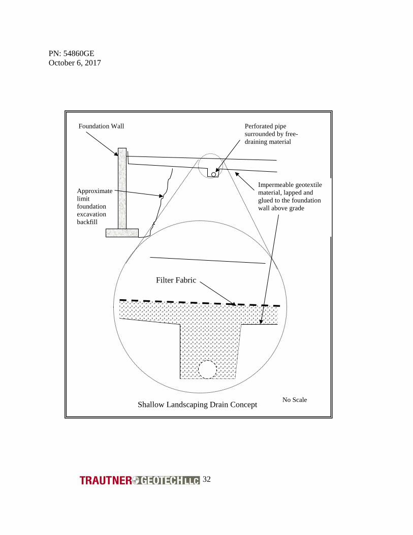
structure. If the roof water is collected in an eave gutter system, or similar, the discharge points of the system must be located away from areas where the water will have access to the foundation backfill or any structure support soils. If downspouts are used, provisions should be made to either collect or direct the water away from the structure. The project civil engineering consultant or builder should develop a drainage scheme for the site. We typically suggest a minimum fall of about eight (8) to ten (10) percent away from the structure, in the absence of design criteria from others. Care should be taken to not direct water onto adjacent property or to areas that would negatively influence existing structures or improvements. 10.5 Landscaping Considerations We recommend against construction of landscaping which requires excessive irrigation. Generally landscaping which uses abundant water requires that the landscaping contractor install topsoil which will retain moisture. The topsoil is often placed in flattened areas near the structure to further trap water and reduce water migration from away from the landscaped areas. Unfortunately, almost all aspects of landscape construction and development of lush vegetation are contrary to the establishment of a relatively dry area adjacent to the foundation walls. Excess water from landscaped areas near the structure can migrate to the foundation system or flatwork support soils, which can result in volume changes in these soils. A relatively common concept used to collect and subsequently reduce the amount of excess irrigation water is to glue or attach an impermeable geotextile fabric or heavy mill plastic to the foundation wall and extend it below the topsoil which is used to establish the landscape vegetation. A thin layer of sand can be placed on top of the geotextile material to both protect the geotextile from punctures and to serve as a medium to promote water migration to the collection trench and perforated pipe. The landscape architect or contractor should be contacted for additional information regarding specific construction considerations for this concept which is shown in the sketch below.
PN: 54860GE October 6, 2017
32
Shallow Landscaping Drain Concept No Scale
Foundation Wall
Approximate limit foundation excavation backfill
Impermeable geotextile material, lapped and glued to the foundation wall above grade
Perforated pipe surrounded by free-draining material
Filter Fabric
PN: 54860GE October 6, 2017
33
A free draining aggregate or sand may be placed in the collection trench around the perforated pipe. The perforated pipe should be graded to allow for positive flow of excess irrigation water away from the structure or other area where additional subsurface water is undesired. Preferably the geotextile material should extend at least ten (10) or more feet from the foundation system. Care should be taken to not place exterior flatwork such as sidewalks or driveways on soils that have been tilled and prepared for landscaping. Tilled soils will settle which can cause damage to the overlying flatwork. Tilled soils placed on sloped areas often “creep” down-slope. Any structure or structural component placed on this material will move down-slope with the tilled soil and may become damaged. 10.6 Soil Sulfate Content, Corrosion Issues The requested scope of our services did not include assessment of the chemical constituents of corrosion potential of the site soils. Most soils in southwest Colorado are not typically corrosive to concrete. There has not been a history of damage to concrete due to sulfate corrosion in the area. We are available to perform soluble sulfate content tests to assess the corrosion potential of the soils on concrete if desired. 10.7 Radon Issues The requested scope of service of this report did not include assessment of the site soils for radon production. Many soils and formational materials in western Colorado produce Radon gas. The structure should be appropriately ventilated to reduce the accumulation of Radon gas in the structure. Several Federal Government agencies including the Environmental Protection Agency (EPA) have information and guidelines available for Radon considerations and home construction. If a radon survey of the site soils is desired, please contact us. 11.0 CONSTRUCTION MONITORING AND TESTING Construction monitoring including engineering observations and materials testing during construction is a critical aspect of the geotechnical engineering contribution to any project. Unexpected subsurface conditions are often encountered during construction. The site foundation excavation should be observed by the geotechnical engineer or a representative during the early stages of the site construction to verify that the actual subsurface soil and water conditions were properly characterized as part of field exploration, laboratory testing and engineering analysis. If the subsurface conditions encountered during construction are different than those that were the basis of the geotechnical engineering report then modifications to the design may be implemented prior to placement of fill materials or foundation concrete.
PN: 54860GE October 6, 2017
34
Compaction testing of fill material should be performed throughout the project construction so that the engineer and contractor may monitor the quality of the fill placement techniques being used at the site. Generally, we recommend that compaction testing be performed for any fill material that is placed as part of the site development. Compaction tests should be performed on each lift of material placed in areas proposed for support of structural components. In addition to compaction testing we recommend that the grain size distribution, clay content and swell potential be evaluated for any imported materials that are planned for use on the site. Concrete tests should be performed on foundation concrete and flatwork. If asphaltic concrete is placed for driveways or aprons near the structure we are available to provide testing of these materials during placement. We are available to develop a testing program for soil, aggregate materials, concrete and asphaltic concrete for this project. 12.0 CONCLUSIONS AND CONSIDERATIONS The information presented in this report is based on our understanding of the proposed construction that was provided to us and on the data obtained from our field and laboratory studies. We recommend that we be contacted during the design and construction phase of this project to aid in the implementation of our recommendations. Please contact us immediately if you have any questions, or if any of the information presented above is not appropriate for the proposed site construction. The recommendations presented above are intended to be used only for this project site and the proposed construction which was provided to us. The recommendations presented above are not suitable for adjacent project sites, or for proposed construction that is different than that outlined for this study. Our recommendations are based on limited field and laboratory sampling and testing. Unexpected subsurface conditions encountered during construction may alter our recommendations. We should be contacted during construction to observe the exposed subsurface soil conditions to provide comments and verification of our recommendations. We are available to review and tailor our recommendations as the project progresses and additional information which may influence our recommendations becomes available.
PN: 54860GE October 6, 2017
35
Please contact us if you have any questions, or if we may be of additional service.
Respectfully submitted, TRAUTNER GEOTECH
Jonathan P. Butler, P.E.
Staff Geotechnical Engineer

APPENDIX A
Logs of Test Borings
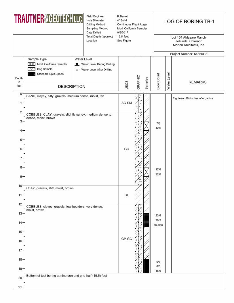
Field Engineer : R.Barrett
Hole Diameter : 4" Solid
Drilling Method : Continuous Flight Auger
Sampling Method : Mod. California Sampler
Date Drilled : 9/6/2017
Total Depth (approx.) : 19.5' feet
Location : See Figure
LOG OF BORING TB-1
Project Number: 54860GE
Morton Architects, Inc.Telluride, Colorado
Lot 154 Aldasaro Ranch
Depth
in
feet
0
1
2
3
4
5
6
7
8
9
10
11
12
13
14
15
16
17
18
19
20
21
DESCRIPTION
Sample Type
Mod. California Sampler
Bag Sample
Standard Split Spoon
Water Level
Water Level During Drilling
Water Level After Drilling
SAND, clayey, silty, gravels, medium dense, moist, tan
COBBLES, CLAY, gravels, slightly sandy, medium dense to dense, moist, brown
CLAY, gravels, stiff, moist, brown
COBBLES, clayey, gravels, few boulders, very dense, moist, brown
Bottom of test boring at nineteen and one-half (19.5) feet
US
CS
SC-SM
GC
CL
GP-GC
GR
AP
HIC
Sa
mp
les
Blo
w C
ou
nt
Wa
ter
Le
ve
l
REMARKS
Eighteen (18) inches of organics
7/6
12/6
17/6
22/6
23/6
28/5
bounce
6/6
6/6
15/6

Field Engineer : R.Barrett
Hole Diameter : 4" Solid
Drilling Method : Continuous Flight Auger
Sampling Method : Mod. California Sampler
Date Drilled : 9/6/2017
Total Depth (approx.) : 17.5' feet
Location : See Figure
LOG OF BORING TB-2
Project Number: 54860GE
Morton Architects, Inc.Telluride, Colorado
Lot 154 Aldasaro Ranch
Depth
in
feet
0
1
2
3
4
5
6
7
8
9
10
11
12
13
14
15
16
17
18
19
20
21
DESCRIPTION
Sample Type
Mod. California Sampler
Bag Sample
Standard Split Spoon
Water Level
Water Level During Drilling
Water Level After Drilling
SAND, clayey, silty, gravels, medium dense, moist, brown
COBBLES, GRAVEL, clayey, silty, slightly sandy, medium dense, moist, brown
CLAY, gravels, stiff, moist, brown
GRAVEL, CLAY, few cobbles, very dense, moist, brown
Bottom of test boring at seventeen and one-half (17.5) feet
US
CS
SC-SM
GC-GM
CL
GC
GR
AP
HIC
Sa
mp
les
Blo
w C
ou
nt
8/6
9/6
17/6
21/6W
ate
r L
eve
l
REMARKS
Eighteen (18) inches of organics
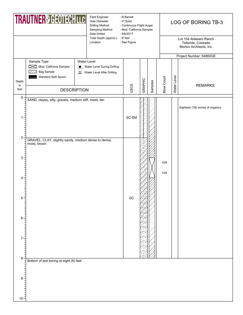
Field Engineer : R.Barrett
Hole Diameter : 4" Solid
Drilling Method : Continuous Flight Auger
Sampling Method : Mod. California Sampler
Date Drilled : 9/6/2017
Total Depth (approx.) : 8' feet
Location : See Figure
LOG OF BORING TB-3
Project Number: 54860GE
Morton Architects, Inc.Telluride, Colorado
Lot 154 Aldasaro Ranch
Depth
in
feet
0
1
2
3
4
5
6
7
8
9
10
DESCRIPTION
Sample Type
Mod. California Sampler
Bag Sample
Standard Split Spoon
Water Level
Water Level During Drilling
Water Level After Drilling
SAND, clayey, silty, gravels, medium stiff, moist, tan
GRAVEL, CLAY, slightly sandy, medium dense to dense, moist, brown
Bottom of test boring at eight (8) feet
US
CS
SC-SM
GC
GR
AP
HIC
Sa
mp
les
Blo
w C
ou
nt
Wa
ter
Le
ve
l
REMARKS
Eighteen (18) inches of organics
10/6
14/6

APPENDIX B
Laboratory Test Result

Tested By: Checked By:
(no specification provided)*
PL= LL= PI=
USCS (D 2487)= AASHTO (M 145)=
D90= D85= D60=D50= D30= D15=D10= Cu= Cc=
Remarks
SM-Silty, Sand with Gravel
13/4"1/2"3/8"#4#8
#10#16#30#40#50#100#200
100989491756664615756545248
26 34 8
SM A-4(2)
9.1060 7.1608 1.07020.1109
9-8-17 9-11-17
D. Hughes
R. Barrett
Engineer Tech.
9-8-17
Steve Morton/Morton AIA
Elliott Res., Lot 154 Aldasoro
54860GE
Material Description
Atterberg Limits (ASTM D 4318)
Classification
Coefficients
Date Received: Date Tested:
Tested By:
Checked By:
Title:
Date Sampled:Location: Test Boring 1Sample Number: C10090-A Depth: 0-3'
Client:
Project:
Project No: Figure: 4.1
TEST RESULTS
Opening Percent Spec.* Pass?
Size Finer (Percent) (X=Fail)
PE
RC
EN
T F
INE
R
0
10
20
30
40
50
60
70
80
90
100
GRAIN SIZE - mm.
0.0010.010.1110100
% +3" % GravelCoarse
% Sand
Fine Silt
% Fines
Clay
0 36 8 8 48
6 in.
3 in.
2 in.
1½
in.
1 in.
¾ in.
½ in.
3/8
in.
#4
#10
#20
#30
#40
#60
#100
#140
#200
Particle Size Distribution Report

Direct Shear Test ResultsASTM D3080-90
Project: Elliot Residence Visual Soil Description: Clayey sandProject Number: 54869GE Type of Specimen: RemoldedLaboratory Number: C10090-C Diameter 1.946 in.Date: 9/28/2017 Thickness 2.0 inProject Technician: RB Sample Source: TB-1@ 4'-8'
FIGURE 4.4
Summary of Sample Data:Initial Moisture Content (%) 7.6Intial Dry Density (P.C.F) 100.8Final Moisture Content (%) 21.8Final Dry Density (P.C.F) 102.4
Residual Direct Shear Test Results:Normal Stress (P.S.I) 2.14 4.29 8.57Max. Shear Stress (P.S.I) 3.25 4.21 5.32
ESTIMATED STRENGTH PARAMETERSAngle of Internal Friction, phi 19Cohesion, P.S.F. 365
0
2
4
6
8
0 5 10
Shea
r Str
ess,
P.S
.I.
Normal Stress, P.S.I.
0123456789
10
0.00 0.05 0.10 0.15 0.20
Shea
r Ste
ss, P
.S.I.
Horizontal Deformation, inches
Figure 4.2

Sample Source
Soil Description
Swell Pressure (P.S.F)
Initial Final
Moisture Content (%) 7.3 15.5
Dry Density (P.C.F) 120.8 128.3
Height (in.) 1.000 0.930
Diameter (in.) 1.94 1.94
Project Number
Date
Figure
SWELL - CONSOLIDATION TEST
SUMMARY OF TEST RESULTS
TB-1@8'
4.3
Sandy Clay with gravel
840
54860GE
September 8, 2017
-8
-7
-6
-5
-4
-3
-2
-1
0
10 100 1000 10000
Co
ns
oli
da
tio
n %
Sw
ell
Pressure (Pounds per Square Foot)
Swell/Consolidation due to wetting under constant load
Water added tosample
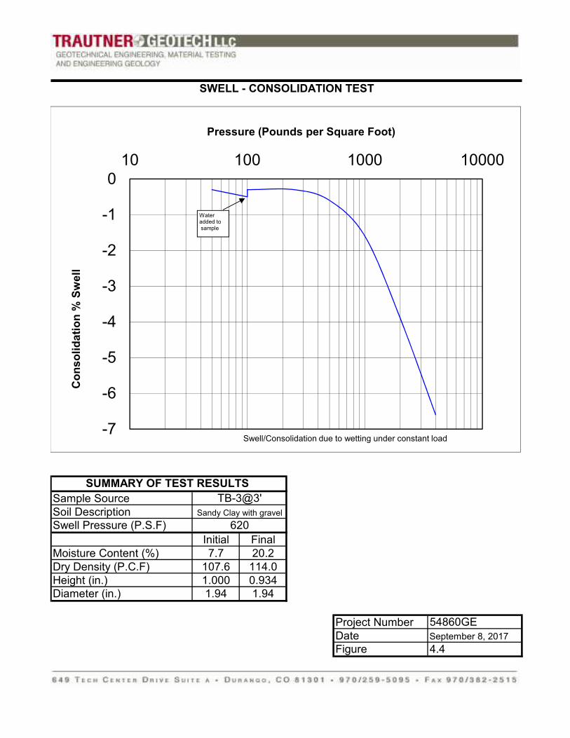
Sample Source
Soil Description
Swell Pressure (P.S.F)
Initial Final
Moisture Content (%) 7.7 20.2
Dry Density (P.C.F) 107.6 114.0
Height (in.) 1.000 0.934
Diameter (in.) 1.94 1.94
Project Number
Date
Figure
SWELL - CONSOLIDATION TEST
SUMMARY OF TEST RESULTS
TB-3@3'
4.4
Sandy Clay with gravel
620
54860GE
September 8, 2017
-7
-6
-5
-4
-3
-2
-1
0
10 100 1000 10000
Co
ns
oli
da
tio
n %
Sw
ell
Pressure (Pounds per Square Foot)
Swell/Consolidation due to wetting under constant load
Water added tosample