Embed Size (px)
Citation preview

Geotechnical Engineering Report Turner Turnpike Widening – Bridge D
Bridge Crossing: South 209th West Avenue
Creek County, Oklahoma
June 1, 2016
Terracon Project No. 04155197
Prepared for:
Garver, LLC
Tulsa, Oklahoma
Prepared by:
Terracon Consultants, Inc.
Tulsa, Oklahoma


TABLE OF CONTENTS
Page
Responsive ■ Resourceful ■ Reliable
INTRODUCTION ............................................................................................................. 1
PROJECT INFORMATION ............................................................................................. 1
2.1 Project Description ............................................................................................... 1
2.2 Site Location and Description .............................................................................. 1
SUBSURFACE CONDITIONS ........................................................................................ 2
3.1 Geology ............................................................................................................... 2
3.2 Soil and Rock Conditions ..................................................................................... 2
3.3 Groundwater ........................................................................................................ 3
BRIDGE FOUNDATION CONSIDERATIONS ................................................................. 4
4.1 Driven Piles .......................................................................................................... 5
4.2 Drilled Shafts ....................................................................................................... 5
4.3 Seismic Considerations........................................................................................ 6
GENERAL COMMENTS ................................................................................................. 6
APPENDIX A – FIELD EXPLORATION
Exhibit A-1 Site Location Map
Exhibit A-2 Boring Location Plan
Exhibit A-3 Field Exploration Description
Exhibits A-4 to A-9 Boring Logs
Exhibit A-10 Fence Diagram: Subsurface Profile
Exhibit A-11 Rock Core Photographs
APPENDIX B – SUPPORTING INFORMATION
Exhibit B-1 Laboratory Testing
Exhibits B-2 to B-4 Grain Size Distribution Curves
Exhibits B-5 to B-9 Table B.1 - B.5: LPILE Parameters for Lateral Capacity Analysis
APPENDIX C – SUPPORTING DOCUMENTS
Exhibit C-1 General Notes
Exhibit C-2 Unified Soil Classification System
Exhibit C-3 AASHTO Soil Classification System
Exhibit C-4 General Notes – Description of Rock Properties

Responsive ■ Resourceful ■ Reliable 1
GEOTECHNICAL ENGINEERING REPORT
TURNER TURNPIKE WIDENING – BRIDGE D
BRIDGE CROSSING: SOUTH 209TH WEST AVENUE
CREEK COUNTY, OKLAHOMA
Terracon Project No. 04155197
June 1, 2016
INTRODUCTION
This geotechnical engineering report has been completed for the proposed bridge along South 209th
West Avenue over the Turner Turnpike Widening in Creek County, Oklahoma (Appendix A, Figure
A-1). Six borings, designated D-1, D-2, D-3, D-4, D-4A, and D-5 were drilled for the project to
depths of approximately 41.5 to 71.5 feet below the existing ground surface. The boring logs and
a boring location plan showing the approximate boring locations are provided in Appendix A of
this report.
The purpose of these services is to provide information and geotechnical engineering
recommendations relative to:
subsurface soil and rock conditions bridge foundations
groundwater conditions LPILE parameters for lateral analysis
PROJECT INFORMATION
2.1 Project Description
Item Description
Boring Layout See Appendix A, Figure A-2 Boring Location Diagram.
Proposed Construction
Bridge D will be a 4-span bridge to be constructed along South 209th
West Avenue over the proposed Turner Turnpike Widening in Creek
County, Oklahoma. We understand that the interior bridge bent
locations will be supported on drilled shafts and the bridge abutments
will be supported on driven piles.
2.2 Site Location and Description
Item Description
Location The intersection of I-44 and South 209th West Avenue in Creek
County, Oklahoma.

Geotechnical Engineering Report
Turner Turnpike Widening – Bridge D (South 209th West Avenue)
Creek County, Oklahoma ■ June 1, 2016 ■ Terracon Project No. 04155197
Responsive ■ Resourceful ■ Reliable 2
SUBSURFACE CONDITIONS
3.1 Geology
Based on the information published in the Oklahoma Department of Transportation manual,
“Engineering Classification of Geologic Materials: Division Eight”, the geology of the project site
consists of the Dewey and Nellie Bly Units. The majority of this portion of the project is mostly
mapped in the Barnsdall and Chanute Units.
The Dewey Unit consists of limestone, shale, and some sandstone. The lower portion is
interbedded limestone and calcareous shale grading upward to massive hard, dark gray
limestone. The total thickness of this unit ranges from about 10 to 32 feet.
The Nellie Bly Unit consists predominantly of yellowish-brown shale and sandy shale with
sandstone and siltstone. The shale ranges from clay shale in lower portion to silty and sandy
shale upward. The total thickness of this unit ranges from about 80 to 280 feet.
3.2 Soil and Rock Conditions
The subsurface conditions encountered in the borings are shown on the boring logs and are briefly
described below. The stratification lines shown on the boring logs represent the approximate
boundary between soil and rock types; in-situ, the transition between materials may be gradual and
indistinct. Classification of bedrock materials was made from disturbed samples and rock cores.
Petrographic analysis may reveal other rock types.
Description Approximate Depth
to Bottom of Stratum Material Encountered
Consistency/
Density
Surface 1 1 6 to 12 inches Asphalt N/A
Surface 2 2 4 inches Topsoil N/A
Stratum 1 3 14.5 to 29 feet Lean to fat clay with varying amounts of
sand; Shaley lean clay
Medium stiff to
hard
Stratum 2 4 5.5 feet Sandy silt; Sand Very stiff;
medium dense
Stratum 3
Encountered to
termination depths of
about 41.5 to 71.5 feet
Highly weathered shale; Shale with
sandstone seams
Soft to
moderately hard
1. Encountered in borings D-1 through D-3.
2. Encountered in boring D-4 and D-5.
3. Encountered in borings D-1, D-2, D-4, and D-5.

Geotechnical Engineering Report
Turner Turnpike Widening – Bridge D (South 209th West Avenue)
Creek County, Oklahoma ■ June 1, 2016 ■ Terracon Project No. 04155197
Responsive ■ Resourceful ■ Reliable 3
Laboratory tests were conducted on selected soil and rock core samples. The test results are
presented on the boring logs in Appendix A and on test report form in Appendix B.
The following table indicates the ground surface elevations and the approximate top of competent
bedrock depth and elevation at the respective boring locations. The depth to the top of competent
bedrock encountered in the borings corresponds to the depths at which the penetration from a
Standard Penetration test (SPT), conducted in accordance to ASTM D 1586, was less than or equal
to 6 inches with 50 blows. Based on current “State of Oklahoma Department of Transportation
Specifications for the Geotechnical Investigations of Bridges and Related Structures”, we understand
that the required rock penetration does not begin until competent bedrock is encountered. The rock
penetration consists of seven continuous passing Texas Cone Penetrometer (TCP) tests spaced at
5-foot intervals for a total of 30 feet of bedrock penetration in accordance with the ODOT
Specifications for Geotechnical Investigations. Thus, depths to top of competent rock and the
corresponding elevations shown in table do not necessarily coincide with the depths to top of
weathered rock and the corresponding elevations shown on the boring logs.
Approximate Competent Bedrock Depth and Elevation
Boring
No.
Ground
Elevation
(feet)
Competent Bedrock Material
Depth to Top of
Competent Rock
(feet)
Elevation of Top of
Competent Rock
(feet)
D-1 787.0 Shale 39.5 747.5
D-2 789.5 Shale 34.0 755.5
D-3 774.4 Shale 9.5 764.9
D-4 792.6 Shale 24 768.6
D-4A 792.5 Shale 24 768.5
D-5 793.6 Shale 14.5 779.1
3.3 Groundwater
The boreholes were observed while drilling and 24 hours after boring completion for the presence
and level of groundwater. Below depths of about 10 feet, we advanced the borings using wet rotary
drilling techniques. We observed groundwater at the following depths and times:
Boring
Groundwater Levels (feet)
While Drilling 24 hours After Drilling
Depth Elevation Depth Elevation
D-1
Not
encountered
to 10.0 feet
Not
encountered
to 777.0 feet
Not
determined N/A

Geotechnical Engineering Report
Turner Turnpike Widening – Bridge D (South 209th West Avenue)
Creek County, Oklahoma ■ June 1, 2016 ■ Terracon Project No. 04155197
Responsive ■ Resourceful ■ Reliable 4
Boring
Groundwater Levels (feet)
While Drilling 24 hours After Drilling
Depth Elevation Depth Elevation
D-2
Not
encountered
to 10.0 feet
Not
encountered
to 779.5 feet
Not
determined N/A
D-3 5.0 769.4 Not
determined N/A
D-4
Not
encountered
to 10.0 feet
Not
encountered
to 782.6 feet
23.0 769.6
D-4A
Not
encountered
to 10.0 feet
Not
encountered
to 782.5 feet
Not
determined N/A
D-5
Not
encountered
to 10.0 feet
Not
encountered
to 783.6 feet
Not
determined N/A
Long-term monitoring with observation wells, sealed from the influence of surface water, would be
required to accurately define the potential range of groundwater conditions. Fluctuations in the
groundwater level should be expected due to seasonal variations in the amount of rainfall, runoff,
water level in the creek and other factors not apparent at the time the borings were drilled. The
possibility of groundwater level fluctuations and the presence of perched water should be
considered when designing and developing the construction plans for the project.
BRIDGE FOUNDATION CONSIDERATIONS
Driven pile foundations can be used to support the bridge abutments and drilled shafts can be
used to support the interior bents. Shale was encountered in the bridge borings. The shale will
adequately support the bridge structure. Specific recommendations regarding the design and
construction of driven pile and drilled shaft foundations are presented in the following sections.
The tables attached in Appendix B present design parameters to be used in LPILE analyses.
The bedrock bearing materials were encountered at the following depths/elevations:
Boring Top of Bedrock Bearing Material (feet)
Depth Elevation
D-1 39.5 747.5
D-2 34.0 755.5
D-3 9.5 764.9

Geotechnical Engineering Report
Turner Turnpike Widening – Bridge D (South 209th West Avenue)
Creek County, Oklahoma ■ June 1, 2016 ■ Terracon Project No. 04155197
Responsive ■ Resourceful ■ Reliable 5
Boring Top of Bedrock Bearing Material (feet)
Depth Elevation
D-4 24 768.6
D-4A 24 768.5
D-5 14.5 779.1
4.1 Driven Piles
Driven steel HP piles driven to practical refusal in the bedrock can be used to support the
abutments. According to AASHTO’s LRFD Bridge Design Specifications, the nominal resistance
of piles driven to bear on hard rock where pile penetration into the rock formation is minimal is
controlled by the structural limit state of the pile. Pile capacity will depend on the cross-section
and the steel grade. The piles should be designed using a maximum working stress in the pile of
25 percent of the steel’s yield strength.
Pile driving through the native overburden soils is not expected to be difficult based on the results
of the borings. However, variations can occur in the density and strength of the soil and the depth
and quality of the bedrock. Because of the high driving resistance anticipated in the bedrock
materials, we recommend that the piles be equipped with driving tips that can endure high driving
stresses. The bridge engineer should note that the upper 10.5 feet of the highly weathered shale
encountered in boring D-1 is somewhat softer than the shale encountered at greater depths.
Piles should be installed in accordance with Section 514 of ODOT’s Standard Specifications for
Highway Construction. All piles should be driven until satisfactory driving resistance is developed
for the design load bearing capacity using an appropriate pile driving formula approved by ODOT.
In the event sufficient driving resistance is encountered before reaching the anticipated tip
elevations, pile driving could be terminated provided it appears the pile has penetrated
approximately 1 to 2 feet into the bedrock.
Driven pile foundations designed and constructed as recommended above are expected to
experience total settlements of less than 1 inch.
4.2 Drilled Shafts
We understand a bridge engineer will design drilled shafts based on the Texas Cone
penetrometer values provided on the attached boring logs. We recommend that the proposed
drilled shafts bear in the shale bedrock. The bridge engineer should note that the upper 4 to 14.5

Geotechnical Engineering Report
Turner Turnpike Widening – Bridge D (South 209th West Avenue)
Creek County, Oklahoma ■ June 1, 2016 ■ Terracon Project No. 04155197
Responsive ■ Resourceful ■ Reliable 6
feet of the highly weathered shale encountered in boring D-2, D-3, and D-4 is somewhat softer
than the shale encountered at greater depths.
A heavy-duty drill rig equipped with a rock auger or core barrel will be required to penetrate the
bedrock. Based on the Texas Cone Penetrometer values measured in our borings, the drilling
contractor should anticipate difficult drilling in the shale bedrock.
Based on the results of the borings, casing may be required to maintain open pier excavations
and control water inflow. To facilitate pier construction, concrete should be on-site and ready for
placement as pier excavations are completed. A sufficient head of concrete should be maintained
in the casing as it is being pulled to prevent an influx of soft soil or water into the excavations.
Also, concrete having a slump of at least 5 inches should be used to prevent the concrete from
arching in the casing.
4.3 Seismic Considerations
Reference Site Classification
2012 AASHTO LRFD Bridge Design Specifications 1 D
1. In general accordance with the 2012 AASHTO LRFD Bridge Design Specifications, Table 3.10.3.1-
1 – Site Class Definitions.
GENERAL COMMENTS
Terracon should be retained to review the final design plans and specifications so comments can
be made regarding interpretation and implementation of our geotechnical recommendations in
the design and specifications. Terracon also should be retained to provide observation and testing
services during grading, excavation, foundation construction and other earth-related construction
phases of the project.
The analysis and recommendations presented in this report are based upon the data obtained
from the borings performed at the indicated locations and from other information discussed in this
report. This report does not reflect variations that may occur between borings, across the site, or
due to the modifying effects of construction or weather. The nature and extent of such variations
may not become evident until during or after construction. If variations appear, we should be
immediately notified so that further evaluation and supplemental recommendations can be
provided.
The scope of services for this project does not include either specifically or by implication any
environmental assessment of the site or identification or prevention of pollutants, hazardous
materials or conditions. If the owner is concerned about the potential for such contamination or
pollution, other studies should be undertaken.

Geotechnical Engineering Report
Turner Turnpike Widening – Bridge D (South 209th West Avenue)
Creek County, Oklahoma ■ June 1, 2016 ■ Terracon Project No. 04155197
Responsive ■ Resourceful ■ Reliable 7
This report has been prepared for the exclusive use of our client for specific application to the
project discussed and has been prepared in accordance with generally accepted geotechnical
engineering practices. No warranties, either express or implied, are intended or made. Site safety,
excavation support, and dewatering requirements are the responsibility of others. In the event
that changes in the nature, design, or location of the project as outlined in this report are planned,
the conclusions and recommendations contained in this report shall not be considered valid
unless Terracon reviews the changes and either verifies or modifies the conclusions of this report
in writing.

APPENDIX A
FIELD EXPLORATION

N© 2016 GOOGLE
APPROXIMATE SCALE IN FEET
1500 0 1000 1500500
Project Mngr:
Approved By:
Checked By:
Drawn By:
Project No.
Scale:
Date:
File No.Consulting Engineers and Scientists
EXHIBIT NO.
9522 EAST 47TH PLACE, UNIT D TULSA, OKLAHOMA 74145FAX. (918) 250-4570PH. (918) 250-0461
CS
JM
CS
MHH
04155197
SEE BAR SCALE
04155197
APRIL 2016
SITE LOCATION MAP
A-1GEOTECHNICAL EXPLORATION
TURNER TURNPIKE WIDENING - BRIDGE DSOUTH 209TH WEST AVENUE OVER TURNER TURNPIKE
CREEK COUNTY, OKLAHOMA
APPROXIMATE SITE LOCATION

APP
ROXI
MATE
SCA
LE IN
FEE
T
050
50
LEGE
NDBO
RING
LOCA
TION
DIAG
RAM
IS F
OR G
ENER
AL LO
CATI
ON O
NLY,
AN
D IS
NOT
INTE
NDED
FOR
CON
STRU
CTIO
N PU
RPOS
ES
N
CS JM CS
MHH
0415
5197
SEE
BAR
SCAL
E
0415
5197
APRI
L 201
6
BORI
NG LO
CATI
ON P
LAN
A-2
GEOT
ECHN
ICAL
EXP
LORA
TION
TURN
ER T
URNP
IKE
WID
ENIN
G - B
RIDG
E D
SOUT
H 20
9TH
WES
T AV
ENUE
OVE
R TU
RNER
TUR
NPIK
E
CREE
K CO
UNTY
, OKL
AHOM
A
BASE
DRA
WIN
G PR
OVID
ED B
Y GA
RVER
STAT
IONS
AND
OFF
SETS
BAS
ED O
N I-4
4 ℄
D-1
D-2
D-3
D-4
D-4A
D-5
BORI
NGST
ATIO
NOF
FSET
ELEV
. (FT
)
D-1
760+
2813
1' RT
787.0
D-2
760+
8490
' RT
789.5
D-3
761+
388'
LT77
4.4
D-4
762+
5596
' LT
792.6
D-4A
762+
6110
2' LT
792.5
D-5
762+
4914
9' LT
793.6
BASE
D ON
I-44
℄

Geotechnical Engineering Report
Turner Turnpike Widening – Bridge D (South 209th West Avenue)
Creek County, Oklahoma ■ June 1, 2016 ■ Terracon Project No. 04155197
Responsive ■ Resourceful ■ Reliable Exhibit A-3
Field Exploration Description
The borings were performed at the approximate locations shown on the Boring Location Plan,
Exhibit A-2, in this Appendix. Terracon’s drill crew laid out the borings with a hand-held GPS unit.
Surface elevations at the boring locations were obtained by Anderson Surveying, Inc. Surface
elevations and stations were referenced to the mag nail, BM #114 (see Exhibit A-2, Boring
Location Plan) with an elevation of 793.33 feet. The locations and elevations of the borings should
be considered accurate only to the degree implied by the means and methods used to define them.
The borings were advanced with an all-terrain rotary drill rig using continuous flight augers and
wash boring techniques. Temporary casing was used to support the side walls of the upper portion
of the bore holes. Representative samples were obtained by the split-barrel sampling procedure
in which a standard 2-inch, O.D. split-barrel sampling spoon that is driven into the bottom of the
boring with a 140-pound drive hammer falling 30 inches. The number of blows required to advance
the sampling spoon the last 12 inches, or less, of an 18-inch sampling interval or portion thereof,
is recorded as the standard penetration resistance value, N. The N value is used to estimate the
in-situ relative density of granular soils and, to a lesser degree of accuracy, the consistency of
cohesive soils and the hardness of weathered bedrock. The sampling depths, penetration
distances, and N values are reported on the boring logs. The samples were tagged for
identification, sealed to reduce moisture loss and returned to the laboratory for further
examination, testing and classification.
The bedrock in the borings was tested using the Texas Highway Department (THD) cone
penetrometer test. The THD cone penetrometer test is a standard test developed by the Texas
Highway Department to determine the strength and hardness of foundation materials in bridge
foundation exploration work. The test is performed by attaching a 3-inch diameter penetrometer
cone to the drill stem and lowering it to the bottom of the borehole. The cone is seated, and then
driven 12 inches with a 140-pound drive hammer falling 30 inches. The number of blows required
for each 6-inch increment is recorded. If more than 100 blows are required for 12 inches of
penetration, the penetration per 50 blows are recorded to the nearest 1/16 inch. The results of
this test are shown on the boring logs.
An automatic drive hammer was used to advance the split-barrel and THD cone penetrometer. A
greater efficiency is achieved with the automatic drive hammer compared to the conventional
safety drive hammer operated with a cathead and rope.
Core samples of bedrock materials were obtained at boring C-2 using a NX-size diamond-bit core
barrel. The percentages of rock core recovered (REC) and Rock Quality Designation (RQD) per
length of core run are shown on the boring log. The RQD is an index obtained by summing the
lengths of rock core pieces that are 4 inches in length or longer divided by the total length of core
run. The percent recovery and RQD values are shown on the boring log in Appendix A.

Geotechnical Engineering Report
Turner Turnpike Widening – Bridge D (South 209th West Avenue)
Creek County, Oklahoma ■ June 1, 2016 ■ Terracon Project No. 04155197
Responsive ■ Resourceful ■ Reliable Exhibit A-3
The drilling operation was supervised by a field engineer, who prepared field logs. The boring
logs include visual classifications of the materials encountered during drilling and the engineer’s
interpretation of subsurface conditions between samples. Based on the material’s texture, the
soil samples were described according to the attached General Notes and classified in
accordance with the Unified Soil Classification System. A brief description of the Unified System
is included in Appendix C. Rock descriptions are in general accordance with the General Notes
for Sedimentary Rock. Petrographic analysis may reveal other rock types.
As required by the Oklahoma Water Resources Board, any borings deeper than 20 feet, or borings
which encounter groundwater or contaminated materials must be grouted or plugged in
accordance with Oklahoma State statutes. One boring log must also be submitted to the
Oklahoma Water Resources Board for each 10 acres of project site area. Terracon backfilled the
borings to comply with the Oklahoma Water Resources Board requirements.

76
91
80
89
18
16
12
13
20
21
18
36-17-19
44-21-23
69-22-47
52-22-30
785
773.5
763.5
12
17
17
18
11
17
17
3-4-7N=11
4-4-7N=11
6-9-10N=19
16-12-11N=23
5-4-4N=8
6-9-12N=21
12-26-41N=67
2.0
13.5
23.5
6" AsphaltLEAN CLAY WITH SAND (CL), dark gray (2.5Y,4/1) andvery dark gray (2.5Y,3/1), stiff
LEAN CLAY (CL), dark grayish-brown (2.5Y,4/2), stiff tovery stiff
FAT CLAY WITH SAND AND SANDSTONE FRAGMENTS(CH), light olive-brown (2.5Y,5/4), stiff to very stiff
trace sand and sandstone fragments, below 18.5 feet
SHALEY LEAN CLAY (CL), dark gray (2.5Y,4/1) and lightyellowish-brown (2.5Y,6/3), hard
Hammer Type: Automatic+Classification estimated from disturbed and cored samples.Petrographic analysis may reveal other rock types.
Stratification lines are approximate. In-situ, the transition may be gradual.
GR
AP
HIC
LO
G
TH
IS B
OR
ING
LO
G IS
NO
T V
ALI
D IF
SE
PA
RA
TE
D F
RO
M O
RIG
INA
L R
EP
OR
T.
G
EO
SM
AR
T L
OG
-NO
WE
LL 0
415
519
7 B
RID
GE
D.G
PJ
South 209th West Avenue over Turner Turnpike Creek County, OklahomaSITE:
Page 1 of 3
Advancement Method:Power Auger to 10 feetWash Boring below 10 feet
Abandonment Method:Backfilled with cuttings above 4’; grouted 4’ to 14’;backfilled with cuttings from 14’ to termination depth.
9522 E 47th Pl Ste DTulsa, OK
Notes:
Project No.: 04155197
Drill Rig: ATV 840
Boring Started: 4/1/2016
BORING LOG NO. D-1Garver, LLCCLIENT:6450 South Lewis Avenue, Tulsa, Oklahoma
Driller: JB
Boring Completed: 4/1/2016
Exhibit: A-4
See Exhibit A-3 for description of fieldprocedures.See Appendix B for description of laboratoryprocedures and additional data (if any).
See Appendix C for explanation of symbols andabbreviations.
PROJECT: Turner Turnpike Widening - Bridge D
PE
RC
EN
T F
INE
S
WA
TE
RC
ON
TE
NT
(%
)
ATTERBERGLIMITS
LL-PL-PISurface Elev.: 787.0 (Ft.)
ELEVATION (Ft.)
SA
MP
LE T
YP
E
WA
TE
R L
EV
EL
OB
SE
RV
AT
ION
S
DE
PT
H (
Ft.)
5
10
15
20
25
RE
CO
VE
RY
(In
.)
UN
CO
NF
INE
DC
OM
PR
ES
SIV
ES
TR
EN
GT
H (
psi)
FIE
LD T
ES
TR
ES
ULT
S
DEPTH
LOCATION See Exhibit A-2
Station: 760+28 Offset: 131' RT
WATER LEVEL OBSERVATIONS
Not Encountered to 10 feet While Drilling

17
20
758
747.5
12
5
30-50/6"
50/3"50/2 1/8"
30/6"
50/5"
50/1/2"50/1/2"
50/3/4"50/5/8"
50/5/8"50/1/4"
29.0
39.5
SHALEY LEAN CLAY (CL), dark gray (2.5Y,4/1) and lightyellowish-brown (2.5Y,6/3), hard (continued)
HIGHLY WEATHERED SHALE+, dark gray (2.5Y,4/1), soft
SHALE+, dark gray (GLEY1,4/N), soft to moderately hard
Hammer Type: Automatic+Classification estimated from disturbed and cored samples.Petrographic analysis may reveal other rock types.
Stratification lines are approximate. In-situ, the transition may be gradual.
GR
AP
HIC
LO
G
TH
IS B
OR
ING
LO
G IS
NO
T V
ALI
D IF
SE
PA
RA
TE
D F
RO
M O
RIG
INA
L R
EP
OR
T.
G
EO
SM
AR
T L
OG
-NO
WE
LL 0
415
519
7 B
RID
GE
D.G
PJ
South 209th West Avenue over Turner Turnpike Creek County, OklahomaSITE:
Page 2 of 3
Advancement Method:Power Auger to 10 feetWash Boring below 10 feet
Abandonment Method:Backfilled with cuttings above 4’; grouted 4’ to 14’;backfilled with cuttings from 14’ to termination depth.
9522 E 47th Pl Ste DTulsa, OK
Notes:
Project No.: 04155197
Drill Rig: ATV 840
Boring Started: 4/1/2016
BORING LOG NO. D-1Garver, LLCCLIENT:6450 South Lewis Avenue, Tulsa, Oklahoma
Driller: JB
Boring Completed: 4/1/2016
Exhibit: A-4
See Exhibit A-3 for description of fieldprocedures.See Appendix B for description of laboratoryprocedures and additional data (if any).
See Appendix C for explanation of symbols andabbreviations.
PROJECT: Turner Turnpike Widening - Bridge D
PE
RC
EN
T F
INE
S
WA
TE
RC
ON
TE
NT
(%
)
ATTERBERGLIMITS
LL-PL-PISurface Elev.: 787.0 (Ft.)
ELEVATION (Ft.)
SA
MP
LE T
YP
E
WA
TE
R L
EV
EL
OB
SE
RV
AT
ION
S
DE
PT
H (
Ft.)
30
35
40
45
50
RE
CO
VE
RY
(In
.)
UN
CO
NF
INE
DC
OM
PR
ES
SIV
ES
TR
EN
GT
H (
psi)
FIE
LD T
ES
TR
ES
ULT
S
DEPTH
LOCATION See Exhibit A-2
Station: 760+28 Offset: 131' RT
WATER LEVEL OBSERVATIONS
Not Encountered to 10 feet While Drilling
17
12715.5
4
5
50/3/8"50/1/8"50/4"
50/1/2"50/1/4"
50/3/8"50/1/8"
50/1/2"50/1/2"50/5"
71.5
SHALE+, dark gray (GLEY1,4/N), soft to moderately hard(continued)
Boring Terminated at 71.5 Feet
Hammer Type: Automatic+Classification estimated from disturbed and cored samples.Petrographic analysis may reveal other rock types.
Stratification lines are approximate. In-situ, the transition may be gradual.
GR
AP
HIC
LO
G
TH
IS B
OR
ING
LO
G IS
NO
T V
ALI
D IF
SE
PA
RA
TE
D F
RO
M O
RIG
INA
L R
EP
OR
T.
G
EO
SM
AR
T L
OG
-NO
WE
LL 0
415
519
7 B
RID
GE
D.G
PJ
South 209th West Avenue over Turner Turnpike Creek County, OklahomaSITE:
Page 3 of 3
Advancement Method:Power Auger to 10 feetWash Boring below 10 feet
Abandonment Method:Backfilled with cuttings above 4’; grouted 4’ to 14’;backfilled with cuttings from 14’ to termination depth.
9522 E 47th Pl Ste DTulsa, OK
Notes:
Project No.: 04155197
Drill Rig: ATV 840
Boring Started: 4/1/2016
BORING LOG NO. D-1Garver, LLCCLIENT:6450 South Lewis Avenue, Tulsa, Oklahoma
Driller: JB
Boring Completed: 4/1/2016
Exhibit: A-4
See Exhibit A-3 for description of fieldprocedures.See Appendix B for description of laboratoryprocedures and additional data (if any).
See Appendix C for explanation of symbols andabbreviations.
PROJECT: Turner Turnpike Widening - Bridge D
PE
RC
EN
T F
INE
S
WA
TE
RC
ON
TE
NT
(%
)
ATTERBERGLIMITS
LL-PL-PISurface Elev.: 787.0 (Ft.)
ELEVATION (Ft.)
SA
MP
LE T
YP
E
WA
TE
R L
EV
EL
OB
SE
RV
AT
ION
S
DE
PT
H (
Ft.)
55
60
65
70
RE
CO
VE
RY
(In
.)
UN
CO
NF
INE
DC
OM
PR
ES
SIV
ES
TR
EN
GT
H (
psi)
FIE
LD T
ES
TR
ES
ULT
S
DEPTH
LOCATION See Exhibit A-2
Station: 760+28 Offset: 131' RT
WATER LEVEL OBSERVATIONS
Not Encountered to 10 feet While Drilling

85
89
98
19
17
19
18
15
39-18-21
43-21-22
44-20-24
776
770
12" AsphaltLEAN CLAY (CL), dark grayish-brown (2.5Y,4/2), mediumstiff to stiff
olive (5Y,4/2), below 8.5 feet
LEAN CLAY (CL), trace sand and sandstone fragments,dark gray (5Y,4/1), very stiff
HIGHLY WEATHERED SHALE+, olive (5Y,5/3) andolive-yellow (5Y,6/6), soft
dark gray (5Y,4/1) to pale olive (5Y,6/4)
8
18
18
14
16
18
2-2-3N=5
3-3-4N=7
4-3-6N=9
9-8-9N=17
16-32-50/5"
50/4 1/2"40/6"
28-35-46N=81
13.5
19.5
Hammer Type: Automatic+Classification estimated from disturbed and cored samples.Petrographic analysis may reveal other rock types.
Stratification lines are approximate. In-situ, the transition may be gradual.
GR
AP
HIC
LO
G
TH
IS B
OR
ING
LO
G IS
NO
T V
ALI
D IF
SE
PA
RA
TE
D F
RO
M O
RIG
INA
L R
EP
OR
T.
G
EO
SM
AR
T L
OG
-NO
WE
LL 0
415
519
7 B
RID
GE
D.G
PJ
South 209th West Avenue over Turner Turnpike Creek County, OklahomaSITE:
Page 1 of 3
Advancement Method:Power Auger to 10 feetWash Boring below 10 feet
Abandonment Method:Backfilled with cuttings above 4’; grouted 4’ to 14’;backfilled with cuttings from 14’ to termination depth.
9522 E 47th Pl Ste DTulsa, OK
Notes:
Project No.: 04155197
Drill Rig: ATV 840
Boring Started: 4/1/2016
BORING LOG NO. D-2Garver, LLCCLIENT:6450 South Lewis Avenue, Tulsa, Oklahoma
Driller: JB
Boring Completed: 4/1/2016
Exhibit: A-5
See Exhibit A-3 for description of fieldprocedures.See Appendix B for description of laboratoryprocedures and additional data (if any).
See Appendix C for explanation of symbols andabbreviations.
PROJECT: Turner Turnpike Widening - Bridge D
PE
RC
EN
T F
INE
S
WA
TE
RC
ON
TE
NT
(%
)
ATTERBERGLIMITS
LL-PL-PISurface Elev.: 789.5 (Ft.)
ELEVATION (Ft.)
SA
MP
LE T
YP
E
WA
TE
R L
EV
EL
OB
SE
RV
AT
ION
S
DE
PT
H (
Ft.)
5
10
15
20
25
WATER LEVEL OBSERVATIONS
Not Encountered to 10 feet While Drilling
RE
CO
VE
RY
(In
.)
UN
CO
NF
INE
DC
OM
PR
ES
SIV
ES
TR
EN
GT
H (
psi)
FIE
LD T
ES
TR
ES
ULT
S
DEPTH
LOCATION See Exhibit A-2
Station: 760+84 Offset: 90' RT

18
18
755.5
HIGHLY WEATHERED SHALE+, olive (5Y,5/3) andolive-yellow (5Y,6/6), soft (continued)
SHALE+, very dark gray (GLEY1,3/N), soft to moderatelyhard
18
10
3
27-40-49N=89
34-50/5"
50/3/4"50/1 1/2"
50/5/8"50/3/8"
50/1"50/1/2"
50/1"50/3/8"50/3"
34.0
Hammer Type: Automatic+Classification estimated from disturbed and cored samples.Petrographic analysis may reveal other rock types.
Stratification lines are approximate. In-situ, the transition may be gradual.
GR
AP
HIC
LO
G
TH
IS B
OR
ING
LO
G IS
NO
T V
ALI
D IF
SE
PA
RA
TE
D F
RO
M O
RIG
INA
L R
EP
OR
T.
G
EO
SM
AR
T L
OG
-NO
WE
LL 0
415
519
7 B
RID
GE
D.G
PJ
South 209th West Avenue over Turner Turnpike Creek County, OklahomaSITE:
Page 2 of 3
Advancement Method:Power Auger to 10 feetWash Boring below 10 feet
Abandonment Method:Backfilled with cuttings above 4’; grouted 4’ to 14’;backfilled with cuttings from 14’ to termination depth.
9522 E 47th Pl Ste DTulsa, OK
Notes:
Project No.: 04155197
Drill Rig: ATV 840
Boring Started: 4/1/2016
BORING LOG NO. D-2Garver, LLCCLIENT:6450 South Lewis Avenue, Tulsa, Oklahoma
Driller: JB
Boring Completed: 4/1/2016
Exhibit: A-5
See Exhibit A-3 for description of fieldprocedures.See Appendix B for description of laboratoryprocedures and additional data (if any).
See Appendix C for explanation of symbols andabbreviations.
PROJECT: Turner Turnpike Widening - Bridge D
PE
RC
EN
T F
INE
S
WA
TE
RC
ON
TE
NT
(%
)
ATTERBERGLIMITS
LL-PL-PISurface Elev.: 789.5 (Ft.)
ELEVATION (Ft.)
SA
MP
LE T
YP
E
WA
TE
R L
EV
EL
OB
SE
RV
AT
ION
S
DE
PT
H (
Ft.)
30
35
40
45
50
WATER LEVEL OBSERVATIONS
Not Encountered to 10 feet While Drilling
RE
CO
VE
RY
(In
.)
UN
CO
NF
INE
DC
OM
PR
ES
SIV
ES
TR
EN
GT
H (
psi)
FIE
LD T
ES
TR
ES
ULT
S
DEPTH
LOCATION See Exhibit A-2
Station: 760+84 Offset: 90' RT

17724
SHALE+, very dark gray (GLEY1,3/N), soft to moderatelyhard (continued)
Boring Terminated at 65.5 Feet3
50/1 1/4"50/5/8"
50/1/2"50/1/2"
50/1/2"50/3/8"50/3"
65.5
Hammer Type: Automatic+Classification estimated from disturbed and cored samples.Petrographic analysis may reveal other rock types.
Stratification lines are approximate. In-situ, the transition may be gradual.
GR
AP
HIC
LO
G
TH
IS B
OR
ING
LO
G IS
NO
T V
ALI
D IF
SE
PA
RA
TE
D F
RO
M O
RIG
INA
L R
EP
OR
T.
G
EO
SM
AR
T L
OG
-NO
WE
LL 0
415
519
7 B
RID
GE
D.G
PJ
South 209th West Avenue over Turner Turnpike Creek County, OklahomaSITE:
Page 3 of 3
Advancement Method:Power Auger to 10 feetWash Boring below 10 feet
Abandonment Method:Backfilled with cuttings above 4’; grouted 4’ to 14’;backfilled with cuttings from 14’ to termination depth.
9522 E 47th Pl Ste DTulsa, OK
Notes:
Project No.: 04155197
Drill Rig: ATV 840
Boring Started: 4/1/2016
BORING LOG NO. D-2Garver, LLCCLIENT:6450 South Lewis Avenue, Tulsa, Oklahoma
Driller: JB
Boring Completed: 4/1/2016
Exhibit: A-5
See Exhibit A-3 for description of fieldprocedures.See Appendix B for description of laboratoryprocedures and additional data (if any).
See Appendix C for explanation of symbols andabbreviations.
PROJECT: Turner Turnpike Widening - Bridge D
PE
RC
EN
T F
INE
S
WA
TE
RC
ON
TE
NT
(%
)
ATTERBERGLIMITS
LL-PL-PISurface Elev.: 789.5 (Ft.)
ELEVATION (Ft.)
SA
MP
LE T
YP
E
WA
TE
R L
EV
EL
OB
SE
RV
AT
ION
S
DE
PT
H (
Ft.)
55
60
65
WATER LEVEL OBSERVATIONS
Not Encountered to 10 feet While Drilling
RE
CO
VE
RY
(In
.)
UN
CO
NF
INE
DC
OM
PR
ES
SIV
ES
TR
EN
GT
H (
psi)
FIE
LD T
ES
TR
ES
ULT
S
DEPTH
LOCATION See Exhibit A-2
Station: 760+84 Offset: 90' RT

5413
12
14
17
14
NP772
769
765
14
14
14
16
3
9-6-12N=18
11-9-13N=22
18-50/6"
26-41-50/6"
50/3 1/2"50/3 3/8"
50/2 3/8"50/1 3/4"
50/3/4"50/1/2"
50/1/2"50/1/8"50/3"
2.5
5.5
9.5
12" AsphaltSANDY SILT (ML), yellowish-brown (10YR,5/8), very stiff
POORLY GRADED SAND (SP), yellow (10YR,7/8) to paleolive (5Y,6/4), medium dense
HIGHLY WEATHED SHALE+, olive-gray (5Y,5/2), soft
SHALE+, olive-gray (5Y,5/2), soft to moderately hard
gray (10YR,5/1), below 25.5 feet
Hammer Type: Automatic+Classification estimated from disturbed and cored samples.Petrographic analysis may reveal other rock types.
Stratification lines are approximate. In-situ, the transition may be gradual.
GR
AP
HIC
LO
G
TH
IS B
OR
ING
LO
G IS
NO
T V
ALI
D IF
SE
PA
RA
TE
D F
RO
M O
RIG
INA
L R
EP
OR
T.
G
EO
SM
AR
T L
OG
-NO
WE
LL 0
415
519
7 B
RID
GE
D.G
PJ
South 209th West Avenue over Turner Turnpike Creek County, OklahomaSITE:
Page 1 of 2
Advancement Method:Power Auger to 6 feetWash Boring below 6 feet
Abandonment Method:Backfilled with cuttings above 4’; grouted 4’ to 14’;backfilled with cuttings from 14’ to termination depth.
9522 E 47th Pl Ste DTulsa, OK
Notes:
Project No.: 04155197
Drill Rig: ATV 840
Boring Started: 4/7/2016
BORING LOG NO. D-3Garver, LLCCLIENT:6450 South Lewis Avenue, Tulsa, Oklahoma
Driller: JB
Boring Completed: 4/7/2016
Exhibit: A-6
See Exhibit A-3 for description of fieldprocedures.See Appendix B for description of laboratoryprocedures and additional data (if any).
See Appendix C for explanation of symbols andabbreviations.
PROJECT: Turner Turnpike Widening - Bridge D
PE
RC
EN
T F
INE
S
WA
TE
RC
ON
TE
NT
(%
)
ATTERBERGLIMITS
LL-PL-PISurface Elev.: 774.4 (Ft.)
ELEVATION (Ft.)
SA
MP
LE T
YP
E
WA
TE
R L
EV
EL
OB
SE
RV
AT
ION
S
DE
PT
H (
Ft.)
5
10
15
20
25
RE
CO
VE
RY
(In
.)
UN
CO
NF
INE
DC
OM
PR
ES
SIV
ES
TR
EN
GT
H (
psi)
FIE
LD T
ES
TR
ES
ULT
S
DEPTH
LOCATION See Exhibit A-2
Station: 761+38 Offset: 8' LT
WATER LEVEL OBSERVATIONS
5 ft While Drilling

17733 1
50/1/2"50/3/8"
50/1 3/8"50/3/4"
50/3/4"50/5/8"50/4"
41.5
SHALE+, olive-gray (5Y,5/2), soft to moderately hard(continued)
Boring Terminated at 41.5 Feet
Hammer Type: Automatic+Classification estimated from disturbed and cored samples.Petrographic analysis may reveal other rock types.
Stratification lines are approximate. In-situ, the transition may be gradual.
GR
AP
HIC
LO
G
TH
IS B
OR
ING
LO
G IS
NO
T V
ALI
D IF
SE
PA
RA
TE
D F
RO
M O
RIG
INA
L R
EP
OR
T.
G
EO
SM
AR
T L
OG
-NO
WE
LL 0
415
519
7 B
RID
GE
D.G
PJ
South 209th West Avenue over Turner Turnpike Creek County, OklahomaSITE:
Page 2 of 2
Advancement Method:Power Auger to 6 feetWash Boring below 6 feet
Abandonment Method:Backfilled with cuttings above 4’; grouted 4’ to 14’;backfilled with cuttings from 14’ to termination depth.
9522 E 47th Pl Ste DTulsa, OK
Notes:
Project No.: 04155197
Drill Rig: ATV 840
Boring Started: 4/7/2016
BORING LOG NO. D-3Garver, LLCCLIENT:6450 South Lewis Avenue, Tulsa, Oklahoma
Driller: JB
Boring Completed: 4/7/2016
Exhibit: A-6
See Exhibit A-3 for description of fieldprocedures.See Appendix B for description of laboratoryprocedures and additional data (if any).
See Appendix C for explanation of symbols andabbreviations.
PROJECT: Turner Turnpike Widening - Bridge D
PE
RC
EN
T F
INE
S
WA
TE
RC
ON
TE
NT
(%
)
ATTERBERGLIMITS
LL-PL-PISurface Elev.: 774.4 (Ft.)
ELEVATION (Ft.)
SA
MP
LE T
YP
E
WA
TE
R L
EV
EL
OB
SE
RV
AT
ION
S
DE
PT
H (
Ft.)
30
35
40R
EC
OV
ER
Y (
In.)
UN
CO
NF
INE
DC
OM
PR
ES
SIV
ES
TR
EN
GT
H (
psi)
FIE
LD T
ES
TR
ES
ULT
S
DEPTH
LOCATION See Exhibit A-2
Station: 761+38 Offset: 8' LT
WATER LEVEL OBSERVATIONS
5 ft While Drilling

73
57
22
18
22
11
18
17
15
43-18-25
36-17-19
784
778
768.5
14
17
17
17
18
18
11
30
3-3-3N=6
3-3-4N=7
3-3-5N=8
10-13-16N=29
27-38-50/6"
23-38-49N=87
29-50/6"
8.5
14.5
24.0
4" TopsoilLEAN CLAY WITH SAND (CL), very dark gray (7.5YR,3/1)to dark grayish-brown (2.5Y,4/2), medium stiff
grayish-brown (2.5Y,5/2) and gray (2.5Y,5/1) at 2 feet
light olive-brown (2.5Y,5/4) to brown (7.5YR,5/4) at 5 feet
SANDY LEAN CLAY (CL), with shale fragments, lightyellowish-brown (2.5Y,6/4) to light olive-brown (2.5Y,5/4),very stiff
HIGHLY WEATHERED SHALE+, gray (5Y,5/1), soft
SHALE+, with sandstone seams, brown (7.5YR,4/3) to darkgray (2.5Y,4/1), soft to moderately hard
Hammer Type: Automatic+Classification estimated from disturbed and cored samples.Petrographic analysis may reveal other rock types.
Stratification lines are approximate. In-situ, the transition may be gradual.
GR
AP
HIC
LO
G
TH
IS B
OR
ING
LO
G IS
NO
T V
ALI
D IF
SE
PA
RA
TE
D F
RO
M O
RIG
INA
L R
EP
OR
T.
G
EO
SM
AR
T L
OG
-NO
WE
LL 0
415
519
7 B
RID
GE
D.G
PJ
South 209th West Avenue over Turner Turnpike Creek County, OklahomaSITE:
Page 1 of 3
Advancement Method:Power Auger to 10 feetWash Boring below 10 feet
Abandonment Method:Backfilled with cuttings above 4’; grouted 4’ to 14’;backfilled with cuttings from 14’ to termination depth.
9522 E 47th Pl Ste DTulsa, OK
Notes:
Project No.: 04155197
Drill Rig: ATV 840
Boring Started: 3/31/2016
BORING LOG NO. D-4Garver, LLCCLIENT:6450 South Lewis Avenue, Tulsa, Oklahoma
Driller: JB
Boring Completed: 3/31/2016
Exhibit: A-7
See Exhibit A-3 for description of fieldprocedures.See Appendix B for description of laboratoryprocedures and additional data (if any).
See Appendix C for explanation of symbols andabbreviations.
PROJECT: Turner Turnpike Widening - Bridge D
PE
RC
EN
T F
INE
S
WA
TE
RC
ON
TE
NT
(%
)
ATTERBERGLIMITS
LL-PL-PISurface Elev.: 792.6 (Ft.)
ELEVATION (Ft.)
SA
MP
LE T
YP
E
WA
TE
R L
EV
EL
OB
SE
RV
AT
ION
S
DE
PT
H (
Ft.)
5
10
15
20
25
RE
CO
VE
RY
(In
.)
UN
CO
NF
INE
DC
OM
PR
ES
SIV
ES
TR
EN
GT
H (
psi)
FIE
LD T
ES
TR
ES
ULT
S
DEPTH
LOCATION See Exhibit A-2
Station: 762+55 Offset: 96' LT
WATER LEVEL OBSERVATIONS
23 ft After 24 Hours
Not Encountered to 10 feet While Drilling

40
60
80
170
320
REC = 100%RQD = 65%
REC = 100%RQD = 53%
REC = 98%RQD = 82%
REC = 98%RQD = 63%
REC = 98%RQD = 93%
REC = 98%RQD = 82%
SHALE+, with sandstone seams, brown (7.5YR,4/3) to darkgray (2.5Y,4/1), soft to moderately hard (continued)
very dark gray (GLEY1,3/N) below 30 feet
Hammer Type: Automatic+Classification estimated from disturbed and cored samples.Petrographic analysis may reveal other rock types.
Stratification lines are approximate. In-situ, the transition may be gradual.
GR
AP
HIC
LO
G
TH
IS B
OR
ING
LO
G IS
NO
T V
ALI
D IF
SE
PA
RA
TE
D F
RO
M O
RIG
INA
L R
EP
OR
T.
G
EO
SM
AR
T L
OG
-NO
WE
LL 0
415
519
7 B
RID
GE
D.G
PJ
South 209th West Avenue over Turner Turnpike Creek County, OklahomaSITE:
Page 2 of 3
Advancement Method:Power Auger to 10 feetWash Boring below 10 feet
Abandonment Method:Backfilled with cuttings above 4’; grouted 4’ to 14’;backfilled with cuttings from 14’ to termination depth.
9522 E 47th Pl Ste DTulsa, OK
Notes:
Project No.: 04155197
Drill Rig: ATV 840
Boring Started: 3/31/2016
BORING LOG NO. D-4Garver, LLCCLIENT:6450 South Lewis Avenue, Tulsa, Oklahoma
Driller: JB
Boring Completed: 3/31/2016
Exhibit: A-7
See Exhibit A-3 for description of fieldprocedures.See Appendix B for description of laboratoryprocedures and additional data (if any).
See Appendix C for explanation of symbols andabbreviations.
PROJECT: Turner Turnpike Widening - Bridge D
PE
RC
EN
T F
INE
S
WA
TE
RC
ON
TE
NT
(%
)
ATTERBERGLIMITS
LL-PL-PISurface Elev.: 792.6 (Ft.)
ELEVATION (Ft.)
SA
MP
LE T
YP
E
WA
TE
R L
EV
EL
OB
SE
RV
AT
ION
S
DE
PT
H (
Ft.)
30
35
40
45
50
RE
CO
VE
RY
(In
.)
UN
CO
NF
INE
DC
OM
PR
ES
SIV
ES
TR
EN
GT
H (
psi)
FIE
LD T
ES
TR
ES
ULT
S
DEPTH
LOCATION See Exhibit A-2
Station: 762+55 Offset: 96' LT
WATER LEVEL OBSERVATIONS
23 ft After 24 Hours
Not Encountered to 10 feet While Drilling

737.555.0
Boring Terminated at 55 Feet
Hammer Type: Automatic+Classification estimated from disturbed and cored samples.Petrographic analysis may reveal other rock types.
Stratification lines are approximate. In-situ, the transition may be gradual.
GR
AP
HIC
LO
G
TH
IS B
OR
ING
LO
G IS
NO
T V
ALI
D IF
SE
PA
RA
TE
D F
RO
M O
RIG
INA
L R
EP
OR
T.
G
EO
SM
AR
T L
OG
-NO
WE
LL 0
415
519
7 B
RID
GE
D.G
PJ
South 209th West Avenue over Turner Turnpike Creek County, OklahomaSITE:
Page 3 of 3
Advancement Method:Power Auger to 10 feetWash Boring below 10 feet
Abandonment Method:Backfilled with cuttings above 4’; grouted 4’ to 14’;backfilled with cuttings from 14’ to termination depth.
9522 E 47th Pl Ste DTulsa, OK
Notes:
Project No.: 04155197
Drill Rig: ATV 840
Boring Started: 3/31/2016
BORING LOG NO. D-4Garver, LLCCLIENT:6450 South Lewis Avenue, Tulsa, Oklahoma
Driller: JB
Boring Completed: 3/31/2016
Exhibit: A-7
See Exhibit A-3 for description of fieldprocedures.See Appendix B for description of laboratoryprocedures and additional data (if any).
See Appendix C for explanation of symbols andabbreviations.
PROJECT: Turner Turnpike Widening - Bridge D
PE
RC
EN
T F
INE
S
WA
TE
RC
ON
TE
NT
(%
)
ATTERBERGLIMITS
LL-PL-PISurface Elev.: 792.6 (Ft.)
ELEVATION (Ft.)
SA
MP
LE T
YP
E
WA
TE
R L
EV
EL
OB
SE
RV
AT
ION
S
DE
PT
H (
Ft.)
55
RE
CO
VE
RY
(In
.)
UN
CO
NF
INE
DC
OM
PR
ES
SIV
ES
TR
EN
GT
H (
psi)
FIE
LD T
ES
TR
ES
ULT
S
DEPTH
LOCATION See Exhibit A-2
Station: 762+55 Offset: 96' LT
WATER LEVEL OBSERVATIONS
23 ft After 24 Hours
Not Encountered to 10 feet While Drilling

768.5 11 30-50/6"
50/3"50/2"
24.0
See Boring D-4 for Soil Stratification
SHALE+, dark gray (2.5Y,4/1) to brown (7.5YR,4/3), soft tomoderately hard
Hammer Type: Automatic+Classification estimated from disturbed and cored samples.Petrographic analysis may reveal other rock types.
Stratification lines are approximate. In-situ, the transition may be gradual.
GR
AP
HIC
LO
G
TH
IS B
OR
ING
LO
G IS
NO
T V
ALI
D IF
SE
PA
RA
TE
D F
RO
M O
RIG
INA
L R
EP
OR
T.
G
EO
SM
AR
T L
OG
-NO
WE
LL 0
415
519
7 B
RID
GE
D.G
PJ
South 209th West Avenue over Turner Turnpike Creek County, OklahomaSITE:
Page 1 of 3
Advancement Method:Power Auger to 10 feetWash Boring below 10 feet
Abandonment Method:Backfilled with cuttings above 4’; grouted 4’ to 14’;backfilled with cuttings from 14’ to termination depth.
9522 E 47th Pl Ste DTulsa, OK
Notes:
Project No.: 04155197
Drill Rig: ATV 840
Boring Started: 3/31/2016
BORING LOG NO. D-4AGarver, LLCCLIENT:6450 South Lewis Avenue, Tulsa, Oklahoma
Driller: JB
Boring Completed: 3/31/2016
Exhibit: A-8
See Exhibit A-3 for description of fieldprocedures.See Appendix B for description of laboratoryprocedures and additional data (if any).
See Appendix C for explanation of symbols andabbreviations.
PROJECT: Turner Turnpike Widening - Bridge D
PE
RC
EN
T F
INE
S
WA
TE
RC
ON
TE
NT
(%
)
ATTERBERGLIMITS
LL-PL-PISurface Elev.: 792.5 (Ft.)
ELEVATION (Ft.)
SA
MP
LE T
YP
E
WA
TE
R L
EV
EL
OB
SE
RV
AT
ION
S
DE
PT
H (
Ft.)
5
10
15
20
25
RE
CO
VE
RY
(In
.)
UN
CO
NF
INE
DC
OM
PR
ES
SIV
ES
TR
EN
GT
H (
psi)
FIE
LD T
ES
TR
ES
ULT
S
DEPTH
LOCATION See Exhibit A-2
Station: 762+61 Offset: 102' LT
WATER LEVEL OBSERVATIONS
Not Encountered to 10 feet While Drilling

4
50/1"50/1"
50/1 1/4"50/3/4"
50/5/8"50/1/4"50/4"
50/1/2"50/1/4"
50/1/2"50/3/8"
SHALE+, dark gray (2.5Y,4/1) to brown (7.5YR,4/3), soft tomoderately hard (continued)
very dark gray (GLEY1,3/N), below 39.5 feet
Hammer Type: Automatic+Classification estimated from disturbed and cored samples.Petrographic analysis may reveal other rock types.
Stratification lines are approximate. In-situ, the transition may be gradual.
GR
AP
HIC
LO
G
TH
IS B
OR
ING
LO
G IS
NO
T V
ALI
D IF
SE
PA
RA
TE
D F
RO
M O
RIG
INA
L R
EP
OR
T.
G
EO
SM
AR
T L
OG
-NO
WE
LL 0
415
519
7 B
RID
GE
D.G
PJ
South 209th West Avenue over Turner Turnpike Creek County, OklahomaSITE:
Page 2 of 3
Advancement Method:Power Auger to 10 feetWash Boring below 10 feet
Abandonment Method:Backfilled with cuttings above 4’; grouted 4’ to 14’;backfilled with cuttings from 14’ to termination depth.
9522 E 47th Pl Ste DTulsa, OK
Notes:
Project No.: 04155197
Drill Rig: ATV 840
Boring Started: 3/31/2016
BORING LOG NO. D-4AGarver, LLCCLIENT:6450 South Lewis Avenue, Tulsa, Oklahoma
Driller: JB
Boring Completed: 3/31/2016
Exhibit: A-8
See Exhibit A-3 for description of fieldprocedures.See Appendix B for description of laboratoryprocedures and additional data (if any).
See Appendix C for explanation of symbols andabbreviations.
PROJECT: Turner Turnpike Widening - Bridge D
PE
RC
EN
T F
INE
S
WA
TE
RC
ON
TE
NT
(%
)
ATTERBERGLIMITS
LL-PL-PISurface Elev.: 792.5 (Ft.)
ELEVATION (Ft.)
SA
MP
LE T
YP
E
WA
TE
R L
EV
EL
OB
SE
RV
AT
ION
S
DE
PT
H (
Ft.)
30
35
40
45
50
RE
CO
VE
RY
(In
.)
UN
CO
NF
INE
DC
OM
PR
ES
SIV
ES
TR
EN
GT
H (
psi)
FIE
LD T
ES
TR
ES
ULT
S
DEPTH
LOCATION See Exhibit A-2
Station: 762+61 Offset: 102' LT
WATER LEVEL OBSERVATIONS
Not Encountered to 10 feet While Drilling

736.5 9
50/7/8"50/1 1/2"45-50/4"55.9
SHALE+, dark gray (2.5Y,4/1) to brown (7.5YR,4/3), soft tomoderately hard (continued)
Boring Terminated at 55.9 Feet
Hammer Type: Automatic+Classification estimated from disturbed and cored samples.Petrographic analysis may reveal other rock types.
Stratification lines are approximate. In-situ, the transition may be gradual.
GR
AP
HIC
LO
G
TH
IS B
OR
ING
LO
G IS
NO
T V
ALI
D IF
SE
PA
RA
TE
D F
RO
M O
RIG
INA
L R
EP
OR
T.
G
EO
SM
AR
T L
OG
-NO
WE
LL 0
415
519
7 B
RID
GE
D.G
PJ
South 209th West Avenue over Turner Turnpike Creek County, OklahomaSITE:
Page 3 of 3
Advancement Method:Power Auger to 10 feetWash Boring below 10 feet
Abandonment Method:Backfilled with cuttings above 4’; grouted 4’ to 14’;backfilled with cuttings from 14’ to termination depth.
9522 E 47th Pl Ste DTulsa, OK
Notes:
Project No.: 04155197
Drill Rig: ATV 840
Boring Started: 3/31/2016
BORING LOG NO. D-4AGarver, LLCCLIENT:6450 South Lewis Avenue, Tulsa, Oklahoma
Driller: JB
Boring Completed: 3/31/2016
Exhibit: A-8
See Exhibit A-3 for description of fieldprocedures.See Appendix B for description of laboratoryprocedures and additional data (if any).
See Appendix C for explanation of symbols andabbreviations.
PROJECT: Turner Turnpike Widening - Bridge D
PE
RC
EN
T F
INE
S
WA
TE
RC
ON
TE
NT
(%
)
ATTERBERGLIMITS
LL-PL-PISurface Elev.: 792.5 (Ft.)
ELEVATION (Ft.)
SA
MP
LE T
YP
E
WA
TE
R L
EV
EL
OB
SE
RV
AT
ION
S
DE
PT
H (
Ft.)
55
RE
CO
VE
RY
(In
.)
UN
CO
NF
INE
DC
OM
PR
ES
SIV
ES
TR
EN
GT
H (
psi)
FIE
LD T
ES
TR
ES
ULT
S
DEPTH
LOCATION See Exhibit A-2
Station: 762+61 Offset: 102' LT
WATER LEVEL OBSERVATIONS
Not Encountered to 10 feet While Drilling

9617
12
12
12
16
45-20-25
788.5
779
14
16
14
18
16
5-7-14N=21
16-22-29N=51
20-31-31N=62
25-24-34N=58
15-21-50/5"
50/2 5/8"50/2 5/8"
50/1 1/2"50/1 1/2"
50/1 3/8"50/1"
5.0
14.5
4" TopsoilSHALEY LEAN CLAY (CL), brown (7.5YR,4/3), very stiff tohard
brownish-yellow (10YR,6/8), below 2 feet
SHALEY LEAN CLAY (CL), pale olive (5Y,6/4), hard
olive-yellow (2.5Y,6/8), below 8.5 feet
SHALE+, olive-yellow (2.5Y,6/8), soft to moderately hard
Hammer Type: Automatic+Classification estimated from disturbed and cored samples.Petrographic analysis may reveal other rock types.
Stratification lines are approximate. In-situ, the transition may be gradual.
GR
AP
HIC
LO
G
TH
IS B
OR
ING
LO
G IS
NO
T V
ALI
D IF
SE
PA
RA
TE
D F
RO
M O
RIG
INA
L R
EP
OR
T.
G
EO
SM
AR
T L
OG
-NO
WE
LL 0
415
519
7 B
RID
GE
D.G
PJ
South 209th West Avenue over Turner Turnpike Creek County, OklahomaSITE:
Page 1 of 2
Advancement Method:Power Auger to 10 feetWash Boring below 10 feet
Abandonment Method:Backfilled with cuttings above 4’; grouted 4’ to 14’;backfilled with cuttings from 14’ to termination depth.
9522 E 47th Pl Ste DTulsa, OK
Notes:
Project No.: 04155197
Drill Rig: ATV 840
Boring Started: 4/8/2016
BORING LOG NO. D-5Garver, LLCCLIENT:6450 South Lewis Avenue, Tulsa, Oklahoma
Driller: JB
Boring Completed: 4/14/2016
Exhibit: A-9
See Exhibit A-3 for description of fieldprocedures.See Appendix B for description of laboratoryprocedures and additional data (if any).
See Appendix C for explanation of symbols andabbreviations.
PROJECT: Turner Turnpike Widening - Bridge D
PE
RC
EN
T F
INE
S
WA
TE
RC
ON
TE
NT
(%
)
ATTERBERGLIMITS
LL-PL-PISurface Elev.: 793.6 (Ft.)
ELEVATION (Ft.)
SA
MP
LE T
YP
E
WA
TE
R L
EV
EL
OB
SE
RV
AT
ION
S
DE
PT
H (
Ft.)
5
10
15
20
25
RE
CO
VE
RY
(In
.)
UN
CO
NF
INE
DC
OM
PR
ES
SIV
ES
TR
EN
GT
H (
psi)
FIE
LD T
ES
TR
ES
ULT
S
DEPTH
LOCATION See Exhibit A-2
Station: 762+49 Offset: 149' LT
WATER LEVEL OBSERVATIONS
Not Encountered to 10 feet While Drilling

14
14747.5
1
3
50/1/2"50/1/4"50/4"
50/7/8"50/1/2"
50/1 1/8"50/5/8"
50/3/4"50/5/8"50/3"
46.0
SHALE+, olive-yellow (2.5Y,6/8), soft to moderately hard(continued)
dark gray (10YR,4/1), below 30.5 feet
Boring Terminated at 46 Feet
Hammer Type: Automatic+Classification estimated from disturbed and cored samples.Petrographic analysis may reveal other rock types.
Stratification lines are approximate. In-situ, the transition may be gradual.
GR
AP
HIC
LO
G
TH
IS B
OR
ING
LO
G IS
NO
T V
ALI
D IF
SE
PA
RA
TE
D F
RO
M O
RIG
INA
L R
EP
OR
T.
G
EO
SM
AR
T L
OG
-NO
WE
LL 0
415
519
7 B
RID
GE
D.G
PJ
South 209th West Avenue over Turner Turnpike Creek County, OklahomaSITE:
Page 2 of 2
Advancement Method:Power Auger to 10 feetWash Boring below 10 feet
Abandonment Method:Backfilled with cuttings above 4’; grouted 4’ to 14’;backfilled with cuttings from 14’ to termination depth.
9522 E 47th Pl Ste DTulsa, OK
Notes:
Project No.: 04155197
Drill Rig: ATV 840
Boring Started: 4/8/2016
BORING LOG NO. D-5Garver, LLCCLIENT:6450 South Lewis Avenue, Tulsa, Oklahoma
Driller: JB
Boring Completed: 4/14/2016
Exhibit: A-9
See Exhibit A-3 for description of fieldprocedures.See Appendix B for description of laboratoryprocedures and additional data (if any).
See Appendix C for explanation of symbols andabbreviations.
PROJECT: Turner Turnpike Widening - Bridge D
PE
RC
EN
T F
INE
S
WA
TE
RC
ON
TE
NT
(%
)
ATTERBERGLIMITS
LL-PL-PISurface Elev.: 793.6 (Ft.)
ELEVATION (Ft.)
SA
MP
LE T
YP
E
WA
TE
R L
EV
EL
OB
SE
RV
AT
ION
S
DE
PT
H (
Ft.)
30
35
40
45
RE
CO
VE
RY
(In
.)
UN
CO
NF
INE
DC
OM
PR
ES
SIV
ES
TR
EN
GT
H (
psi)
FIE
LD T
ES
TR
ES
ULT
S
DEPTH
LOCATION See Exhibit A-2
Station: 762+49 Offset: 149' LT
WATER LEVEL OBSERVATIONS
Not Encountered to 10 feet While Drilling

FOUNDATION REPORT
(SHEET 1 OF 2)
Turner Turnpike Widening - Bridge D
South 209th West Avenue over Turner Turnpike
Based on the information published in the Oklahoma Department of
Transportation manual, "Engineering Classification of Geologic Materials:
Division Eight", the geology of the project site consists of the Dewey and
Nellie Bly Units. The majority of this portion of the project is mostly mapped
in the Barnsdall and Chanute Units.
The Dewey Unit consists of limestone, shale, and some sandstone. The
lower portion is interbedded limestone and calcareous shale grading upward
to massive hard, dark gray limestone. The total thickness of this unit ranges
from about 10 to 32 feet.
The Nellie Bly Unit consists predominantly of yellowish-brown shale and
sandy shale with sandstone and siltstone. The shale ranges from clay shale
in lower portion to silty and sandy shale upward. The total thickness of this
unit ranges from about 80 to 280 feet.
786.5
785.0
782.0
778.5
773.5
768.5
763.5
758.5
757.5
752.5
747.5
746.5
741.5
736.5
731.5
731.0
726.5
721.5
716.5
716.0
787.0
785.0
773.5
768.5
763.5
758.0
747.5
787.5
784.5
781.0
776.0
771.0
769.0
766.0
761.0
756.0
755.0
750.0
745.0
740.0
739.5
735.0
730.0
725.0
724.5
789.5
781.0
776.0
770.0
766.0
755.5
773.4
771.9
769.4
765.9
763.9
758.9
753.9
748.9
748.4
743.9
738.9
733.9
733.4
774.4
771.9
768.9
764.9
748.9
ROCK REC = 100%
RQD = 65%
UCS = 30
ROCK REC = 100%
RQD = 53%
UCS = 40
ROCK REC = 98%
RQD = 82%
UCS = 60
ROCK REC = 98%
RQD = 63%
UCS = 80
ROCK REC = 98%
RQD = 93%
UCS = 170
ROCK REC = 98%
RQD = 82%
UCS 320
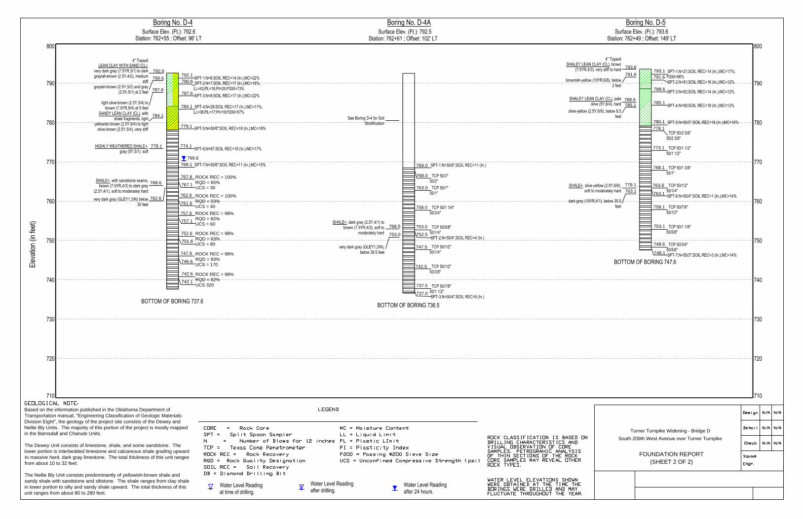
FOUNDATION REPORT
(SHEET 2 OF 2)
Turner Turnpike Widening - Bridge D
South 209th West Avenue over Turner Turnpike
Based on the information published in the Oklahoma Department of
Transportation manual, "Engineering Classification of Geologic Materials:
Division Eight", the geology of the project site consists of the Dewey and
Nellie Bly Units. The majority of this portion of the project is mostly mapped
in the Barnsdall and Chanute Units.
The Dewey Unit consists of limestone, shale, and some sandstone. The
lower portion is interbedded limestone and calcareous shale grading upward
to massive hard, dark gray limestone. The total thickness of this unit ranges
from about 10 to 32 feet.
The Nellie Bly Unit consists predominantly of yellowish-brown shale and
sandy shale with sandstone and siltstone. The shale ranges from clay shale
in lower portion to silty and sandy shale upward. The total thickness of this
unit ranges from about 80 to 280 feet.
792.1
790.6
787.6
784.1
779.1
774.1
769.6
769.1
767.6
767.1
762.6
761.6
757.6
757.1
752.6
751.6
747.6
746.6
742.6
742.1
792.6
790.6
787.6
784.1
778.1
768.6
762.6
769.0
768.0
763.0
758.0
753.0
752.5
747.5
742.5
737.5
737.0
768.5
753.0
793.1
791.6
788.6
785.1
780.1
778.1
773.1
768.1
763.6
763.1
758.1
753.1
748.6
748.1
793.6
791.6
788.6
785.1
779.1
763.1

Exhibit A-11
Boring D-4 Depth: 25.0’ to 30.0’ – Recovery: 100%; RQD = 65% Depth: 30.0’ to 35.0’ – Recovery: 100%; RQD = 53%
Boring D-4 Depth: 35.0’ to 40.0’ – Recovery: 98%; RQD = 82% Depth: 40.0’ to 45.0’ – Recovery: 98%; RQD = 63%

Exhibit A-11
Boring D-4 Depth: 45.0’ to 50.0’ – Recovery: 98%; RQD = 93% Depth: 50.0’ to 55.0’ – Recovery: 98%; RQD = 82%

APPENDIX B
SUPPORTING INFORMATION
Geotechnical Engineering Report
Turner Turnpike Widening – Bridge D (South 209th West Avenue)
Creek County, Oklahoma ■ June 1, 2016 ■ Terracon Project No. 04155197
Responsive ■ Resourceful ■ Reliable Exhibit B-1
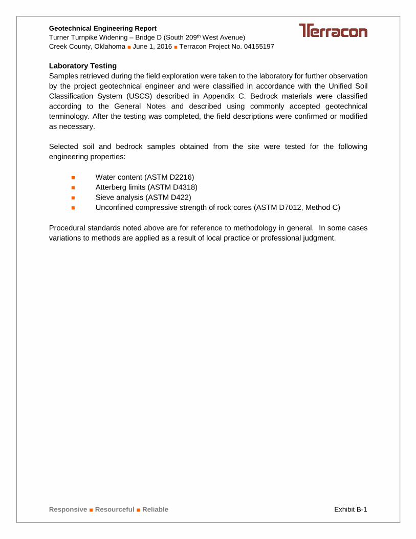
Laboratory Testing
Samples retrieved during the field exploration were taken to the laboratory for further observation
by the project geotechnical engineer and were classified in accordance with the Unified Soil
Classification System (USCS) described in Appendix C. Bedrock materials were classified
according to the General Notes and described using commonly accepted geotechnical
terminology. After the testing was completed, the field descriptions were confirmed or modified
as necessary.
Selected soil and bedrock samples obtained from the site were tested for the following
engineering properties:
Water content (ASTM D2216)
Atterberg limits (ASTM D4318)
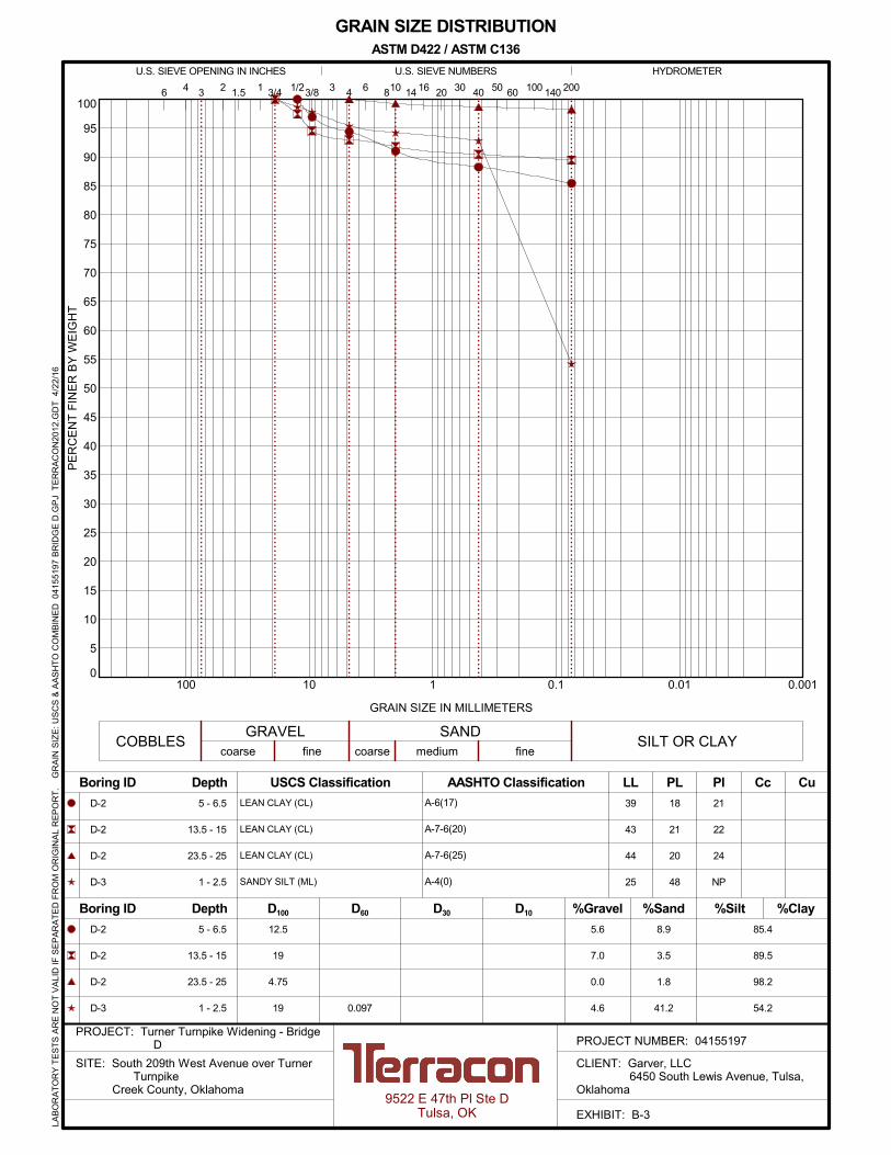
Sieve analysis (ASTM D422)
Unconfined compressive strength of rock cores (ASTM D7012, Method C)
Procedural standards noted above are for reference to methodology in general. In some cases
variations to methods are applied as a result of local practice or professional judgment.

0
5
10
15
20
25
30
35
40
45
50
55
60
65
70
75
80
85
90
95
100
0.0010.010.1110100
6 16 20 30 40
GRAIN SIZE DISTRIBUTION
U.S. SIEVE OPENING IN INCHES
USCS Classification AASHTO Classification Boring ID Depth LL
D100 D30
Cc Cu
Boring ID Depth D60 %Clay
36
44
69
52
U.S. SIEVE NUMBERS
SILT OR CLAY
4 501.5 2006 810 14
12.5
9.5
12.5
19
7.4
4.8
8.5
7.1
16.6
4.2
12.0
3.6
D-1
D-1
D-1
D-1
41 3/4 1/2 60
fine
HYDROMETER
PL PI
D10 %Gravel %Sand %Silt
17
21
22
22
19
23
47
30
3/8 3 100 1403 2
COBBLESGRAVEL SAND
coarse medium
GRAIN SIZE IN MILLIMETERS
PE
RC
EN
T F
INE
R B
Y W
EIG
HT
coarse fine
LEAN CLAY with SAND (CL)
LEAN CLAY (CL)
FAT CLAY with SAND (CH)
FAT CLAY (CH)
A-6(13)
A-7-6(22)
A-7-6(40)
A-7-6(29)
D-1
D-1
D-1
D-1
76.0
91.0
79.5
89.3
0.5 - 2
5 - 6.5
13.5 - 15
18.5 - 20
0.5 - 2
5 - 6.5
13.5 - 15
18.5 - 20
ASTM D422 / ASTM C136
9522 E 47th Pl Ste DTulsa, OK
PROJECT NUMBER: 04155197PROJECT: Turner Turnpike Widening - Bridge
D
SITE: South 209th West Avenue over TurnerTurnpike
Creek County, Oklahoma
CLIENT: Garver, LLC 6450 South Lewis Avenue, Tulsa,Oklahoma
EXHIBIT: B-2
LAB
OR
AT
OR
Y T
ES
TS
AR
E N
OT
VA
LID
IF S
EP
AR
AT
ED
FR
OM
OR
IGIN
AL
RE
PO
RT
.
GR
AIN
SIZ
E: U
SC
S &
AA
SH
TO
CO
MB
INE
D 0
415
5197
BR
IDG
E D
.GP
J T
ER
RA
CO
N20
12.G
DT
4/2
2/16
0
5
10
15
20
25
30
35
40
45
50
55
60
65
70
75
80
85
90
95
100
0.0010.010.1110100
6 16 20 30 40
GRAIN SIZE DISTRIBUTION
U.S. SIEVE OPENING IN INCHES
USCS Classification AASHTO Classification Boring ID Depth LL
D100 D30
Cc Cu
Boring ID Depth D60 %Clay
39
43
44
25
U.S. SIEVE NUMBERS
SILT OR CLAY
4 501.5 2006 810 14
12.5
19
4.75
19
5.6
7.0
0.0
4.6
8.9
3.5
1.8
41.2
D-2
D-2
D-2
D-3
41 3/4 1/2 60
fine
HYDROMETER
PL PI
D10 %Gravel %Sand %Silt
18
21
20
48
21
22
24
NP
3/8 3 100 1403 2
COBBLESGRAVEL SAND
coarse medium
GRAIN SIZE IN MILLIMETERS
PE
RC
EN
T F
INE
R B
Y W
EIG
HT
coarse fine
LEAN CLAY (CL)
LEAN CLAY (CL)
LEAN CLAY (CL)
SANDY SILT (ML)
A-6(17)
A-7-6(20)
A-7-6(25)
A-4(0)
D-2
D-2
D-2
D-3 0.097
85.4
89.5
98.2
54.2
5 - 6.5
13.5 - 15
23.5 - 25
1 - 2.5
5 - 6.5
13.5 - 15
23.5 - 25
1 - 2.5
ASTM D422 / ASTM C136
9522 E 47th Pl Ste DTulsa, OK
PROJECT NUMBER: 04155197PROJECT: Turner Turnpike Widening - Bridge
D
SITE: South 209th West Avenue over TurnerTurnpike
Creek County, Oklahoma
CLIENT: Garver, LLC 6450 South Lewis Avenue, Tulsa,Oklahoma
EXHIBIT: B-3
LAB
OR
AT
OR
Y T
ES
TS
AR
E N
OT
VA
LID
IF S
EP
AR
AT
ED
FR
OM
OR
IGIN
AL
RE
PO
RT
.
GR
AIN
SIZ
E: U
SC
S &
AA
SH
TO
CO
MB
INE
D 0
415
5197
BR
IDG
E D
.GP
J T
ER
RA
CO
N20
12.G
DT
4/2
2/16

0
5
10
15
20
25
30
35
40
45
50
55
60
65
70
75
80
85
90
95
100
0.0010.010.1110100
6 16 20 30 40
GRAIN SIZE DISTRIBUTION
U.S. SIEVE OPENING IN INCHES
USCS Classification AASHTO Classification Boring ID Depth LL
D100 D30
Cc Cu
Boring ID Depth D60 %Clay
43
36
45
U.S. SIEVE NUMBERS
SILT OR CLAY
4 501.5 2006 810 14
9.5
19
9.5
5.2
16.7
0.4
21.5
26.4
3.4
D-4
D-4
D-5
41 3/4 1/2 60
fine
HYDROMETER
PL PI
D10 %Gravel %Sand %Silt
18
17
20
25
19
25
3/8 3 100 1403 2
COBBLESGRAVEL SAND
coarse medium
GRAIN SIZE IN MILLIMETERS
PE
RC
EN
T F
INE
R B
Y W
EIG
HT
coarse fine
LEAN CLAY with SAND (CL)
SANDY LEAN CLAY with GRAVEL (CL)
LEAN CLAY (CL)
A-7-6(17)
A-6(8)
A-7-6(26)
D-4
D-4
D-5
0.139
73.3
56.9
96.2
2 - 3.5
8.5 - 10
0.5 - 2
2 - 3.5
8.5 - 10
0.5 - 2
ASTM D422 / ASTM C136
9522 E 47th Pl Ste DTulsa, OK
PROJECT NUMBER: 04155197PROJECT: Turner Turnpike Widening - Bridge
D
SITE: South 209th West Avenue over TurnerTurnpike
Creek County, Oklahoma
CLIENT: Garver, LLC 6450 South Lewis Avenue, Tulsa,Oklahoma
EXHIBIT: B-4
LAB
OR
AT
OR
Y T
ES
TS
AR
E N
OT
VA
LID
IF S
EP
AR
AT
ED
FR
OM
OR
IGIN
AL
RE
PO
RT
.
GR
AIN
SIZ
E: U
SC
S &
AA
SH
TO
CO
MB
INE
D 0
415
5197
BR
IDG
E D
.GP
J T
ER
RA
CO
N20
12.G
DT
4/2
2/16
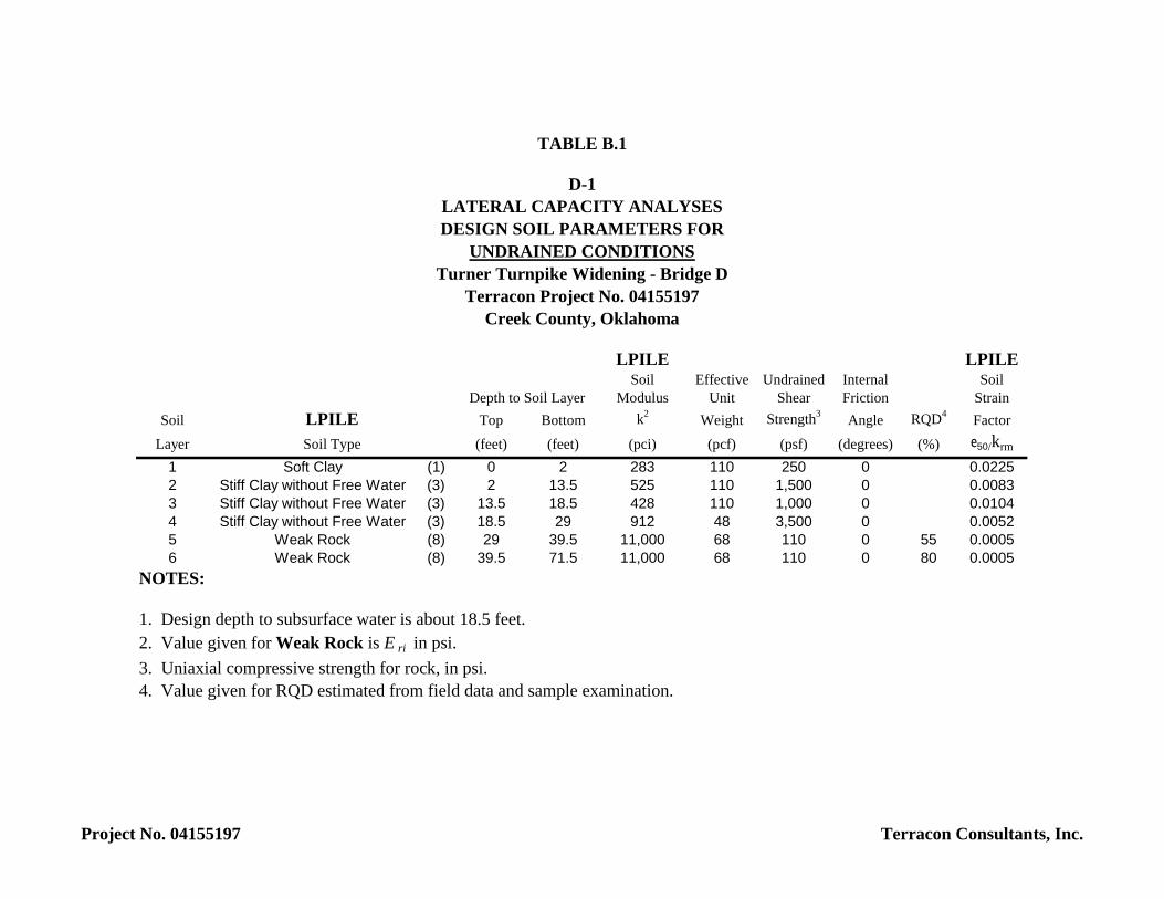
LPILE LPILESoil Effective Undrained Internal Soil
Modulus Unit Shear Friction StrainSoil Top Bottom k2 Weight Strength3 Angle RQD4 Factor
Layer (feet) (feet) (pci) (pcf) (psf) (degrees) (%) e50/krm
1 Soft Clay (1) 0 2 283 110 250 0 0.02252 Stiff Clay without Free Water (3) 2 13.5 525 110 1,500 0 0.00833 Stiff Clay without Free Water (3) 13.5 18.5 428 110 1,000 0 0.01044 Stiff Clay without Free Water (3) 18.5 29 912 48 3,500 0 0.00525 Weak Rock (8) 29 39.5 11,000 68 110 0 55 0.00056 Weak Rock (8) 39.5 71.5 11,000 68 110 0 80 0.0005
NOTES:
1. Design depth to subsurface water is about 18.5 feet.2. Value given for Weak Rock is E ri in psi.3. Uniaxial compressive strength for rock, in psi.4. Value given for RQD estimated from field data and sample examination.
UNDRAINED CONDITIONS
Creek County, Oklahoma
Turner Turnpike Widening - Bridge DTerracon Project No. 04155197
Depth to Soil Layer
TABLE B.1
D-1LATERAL CAPACITY ANALYSESDESIGN SOIL PARAMETERS FOR
LPILESoil Type
Project No. 04155197 Terracon Consultants, Inc.

LPILE LPILESoil Effective Undrained Internal Soil
Modulus Unit Shear Friction StrainSoil Top Bottom k2 Weight Strength3 Angle RQD4 Factor
Layer (feet) (feet) (pci) (pcf) (psf) (degrees) (%) e50/krm
1 Soft Clay (1) 0 2 283 105 250 0 0.02252 Stiff Clay without Free Water (3) 2 8.5 428 110 1,000 0 0.01043 Stiff Clay without Free Water (3) 8.5 19.5 622 110 2,000 0 0.00714 Weak Rock (8) 19.5 34 11,000 68 110 0 55 0.00055 Weak Rock (8) 34 65.5 11,000 68 110 0 80 0.0005
NOTES:
1. Design depth to subsurface water is about 19.5 feet.2. Value given for Weak Rock is E ri in psi.3. Uniaxial compressive strength for rock, in psi.4. Value given for RQD estimated from field data and sample examination.
Depth to Soil Layer
Soil Type
Creek County, Oklahoma
D-2
TABLE B.2
LATERAL CAPACITY ANALYSES
UNDRAINED CONDITIONS
LPILE
Turner Turnpike Widening - Bridge DTerracon Project No. 04155197
DESIGN SOIL PARAMETERS FOR
Project No. 04155197 Terracon Consultants, Inc.

LPILE LPILESoil Effective Undrained Internal Soil
Modulus Unit Shear Friction StrainSoil Top Bottom k2 Weight Strength3 Angle RQD4 Factor
Layer (feet) (feet) (pci) (pcf) (psf) (degrees) (%) e50/krm
1 Silt (7) 0 2.5 25 110 250 0 0.02252 Sand (4) 2.5 5.5 35 115 2,000 27 ----3 Weak Rock (8) 5.5 9 11,000 68 110 0 55 0.00054 Weak Rock (8) 9 41.5 11,000 68 110 0 80 0.0005
NOTES:
1. Design depth to subsurface water is about 5 feet.2. Value given for Weak Rock is E ri in psi.3. Uniaxial compressive strength for rock, in psi.4. Value given for RQD estimated from field data and sample examination.
LATERAL CAPACITY ANALYSES
Soil Type
Depth to Soil Layer
Turner Turnpike Widening - Bridge DTerracon Project No. 04155197
UNDRAINED CONDITIONS
D-3
Creek County, Oklahoma
DESIGN SOIL PARAMETERS FOR
LPILE
TABLE B.3
Project No. 04155197 Terracon Consultants, Inc.

LPILE LPILESoil Effective Undrained Internal Soil
Modulus Unit Shear Friction StrainSoil Top Bottom k2 Weight Strength3 Angle RQD4 Factor
Layer (feet) (feet) (pci) (pcf) (psf) (degrees) (%) e50/krm
1 Sand (1) 0 2 132 105 250 0 ----2 Stiff Clay without Free Water (3) 2 8.5 428 110 1,000 0 0.01043 Stiff Clay without Free Water (3) 8.5 14.5 1,008 110 4,000 0 0.00484 Weak Rock (8) 14.5 24 11,000 130 110 0 55 0.00055 Weak Rock (8) 24 55 11,000 68 110 0 80 0.0005
NOTES:
1. Design depth to subsurface water is about 23 feet.2. Value given for Weak Rock is E ri in psi.3. Uniaxial compressive strength for rock, in psi.4. Value given for RQD estimated from field data and sample examination.
Turner Turnpike Widening - Bridge DTerracon Project No. 04155197
Creek County, Oklahoma
Depth to Soil LayerLPILESoil Type
TABLE B.4
D-4 and D-4A
DESIGN SOIL PARAMETERS FORUNDRAINED CONDITIONS
LATERAL CAPACITY ANALYSES
Project No. 04155197 Terracon Consultants, Inc.

LPILE LPILESoil Effective Undrained Internal Soil
Modulus Unit Shear Friction StrainSoil Top Bottom k2 Weight Strength3 Angle RQD4 Factor
Layer (feet) (feet) (pci) (pcf) (psf) (degrees) (%) e50/krm
1 Soft Clay (1) 0 2 283 110 250 0 0.02252 Stiff Clay without Free Water (3) 2 14.5 1,008 110 4,000 0 0.00483 Weak Rock (8) 14.5 25 11,000 130 110 0 80 0.00054 Weak Rock (8) 25 46 11,000 68 110 0 80 0.0005
NOTES:
1. Design depth to subsurface water is about 25 feet.
3. Uniaxial compressive strength for rock, in psi.4. Value given for RQD estimated from field data and sample examination.
Terracon Project No. 04155197Creek County, Oklahoma
Depth to Soil LayerLPILESoil Type
2. Value given for Weak Rock is E ri in psi.
TABLE B.5
D-5LATERAL CAPACITY ANALYSESDESIGN SOIL PARAMETERS FOR
UNDRAINED CONDITIONSTurner Turnpike Widening - Bridge D
Project No. 04155197 Terracon Consultants, Inc.

APPENDIX C
SUPPORTING DOCUMENTS

01 - 1011 - 30
> 30
RELATIVE PROPORTIONS OF FINES
Descriptive Term(s)of other constituents
Percent ofDry Weight
Hand Penetrometer
Torvane
Standard PenetrationTest (blows per foot)
Photo-Ionization Detector
Organic Vapor Analyzer
Texas Cone Penetrometer
TraceWithModifier
Water Level Aftera Specified Period of Time
GRAIN SIZE TERMINOLOGYRELATIVE PROPORTIONS OF SAND AND GRAVEL
TraceWithModifier
Standard Penetration orN-Value
Blows/Ft.
Descriptive Term(Consistency)
Loose
Very Stiff
Standard Penetration orN-Value
Blows/Ft.
Ring SamplerBlows/Ft.
Ring SamplerBlows/Ft.
Medium Dense
Dense
Very Dense
0 - 1 < 3
4 - 9 2 - 4 3 - 4
Medium-Stiff 5 - 9
30 - 50
WA
TE
R L
EV
EL
Auger
Shelby Tube
Grab Sample
FIE
LD
TE
ST
S
DESCRIPTION OF SYMBOLS AND ABBREVIATIONS
Descriptive Term(Density)
Non-plasticLowMediumHigh
BouldersCobblesGravelSandSilt or Clay
10 - 18
> 50 15 - 30 19 - 42
> 30 > 42
_
Water levels indicated on the soil boringlogs are the levels measured in theborehole at the times indicated.Groundwater level variations will occurover time. In low permeability soils,accurate determination of groundwaterlevels is not possible with short termwater level observations.
CONSISTENCY OF FINE-GRAINED SOILS
(50% or more passing the No. 200 sieve.)Consistency determined by laboratory shear strength testing, field
visual-manual procedures or standard penetration resistance
DESCRIPTIVE SOIL CLASSIFICATION
> 8,000
Unless otherwise noted, Latitude and Longitude are approximately determined using a hand-held GPS device. The accuracyof such devices is variable. Surface elevation data annotated with +/- indicates that no actual topographical survey wasconducted to confirm the surface elevation. Instead, the surface elevation was approximately determined from topographicmaps of the area.
Soil classification is based on the Unified Soil Classification System. Coarse Grained Soils have more than 50% of their dryweight retained on a #200 sieve; their principal descriptors are: boulders, cobbles, gravel or sand. Fine Grained Soils haveless than 50% of their dry weight retained on a #200 sieve; they are principally described as clays if they are plastic, andsilts if they are slightly plastic or non-plastic. Major constituents may be added as modifiers and minor constituents may beadded according to the relative proportions based on grain size. In addition to gradation, coarse-grained soils are definedon the basis of their in-place relative density and fine-grained soils on the basis of their consistency.
Plasticity Index
8 - 15
Split Spoon
Rock Core
PLASTICITY DESCRIPTION
Term
< 1515 - 29> 30
Descriptive Term(s)of other constituents
Water InitiallyEncountered
Water Level After aSpecified Period of Time
Major Componentof Sample
Percent ofDry Weight
(More than 50% retained on No. 200 sieve.)Density determined by Standard Penetration Resistance
Includes gravels, sands and silts.
Hard
Very Loose 0 - 3 0 - 6 Very Soft
7 - 18 Soft
10 - 29 19 - 58
59 - 98 Stiff
less than 500
500 to 1,000
1,000 to 2,000
2,000 to 4,000
4,000 to 8,000> 99
LOCATION AND ELEVATION NOTES
SA
MP
LIN
G
< 55 - 12> 12
No Recovery
RELATIVE DENSITY OF COARSE-GRAINED SOILS
Particle Size
Over 12 in. (300 mm)12 in. to 3 in. (300mm to 75mm)3 in. to #4 sieve (75mm to 4.75 mm)#4 to #200 sieve (4.75mm to 0.075mmPassing #200 sieve (0.075mm)
ST
RE
NG
TH
TE
RM
S Unconfined CompressiveStrength, Qu, psf
4 - 8
GENERAL NOTES
Texas Cone
(HP)
(T)
(b/f)
(PID)
(OVA)
(TCP)
Pressure Meter
Exhibit C-1
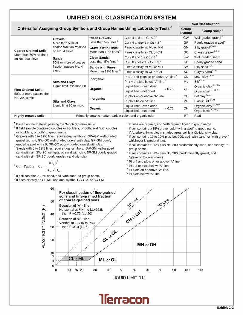
UNIFIED SOIL CLASSIFICATION SYSTEM
Criteria for Assigning Group Symbols and Group Names Using Laboratory Tests A Soil Classification
Group Symbol
Group Name B
Coarse Grained Soils: More than 50% retained on No. 200 sieve
Gravels: More than 50% of coarse fraction retained on No. 4 sieve
Clean Gravels: Less than 5% fines C
Cu 4 and 1 Cc 3 E GW Well-graded gravel F
Cu 4 and/or 1 Cc 3 E GP Poorly graded gravel F
Gravels with Fines: More than 12% fines C
Fines classify as ML or MH GM Silty gravel F,G,H
Fines classify as CL or CH GC Clayey gravel F,G,H
Sands: 50% or more of coarse fraction passes No. 4 sieve
Clean Sands: Less than 5% fines D
Cu 6 and 1 Cc 3 E SW Well-graded sand I
Cu 6 and/or 1 Cc 3 E SP Poorly graded sand I
Sands with Fines: More than 12% fines D
Fines classify as ML or MH SM Silty sand G,H,I
Fines classify as CL or CH SC Clayey sand G,H,I
Fine-Grained Soils: 50% or more passes the No. 200 sieve
Silts and Clays: Liquid limit less than 50
Inorganic: PI 7 and plots on or above “A” line J CL Lean clay K,L,M
PI 4 or plots below “A” line J ML Silt K,L,M
Organic: Liquid limit - oven dried
0.75 OL Organic clay K,L,M,N
Liquid limit - not dried Organic silt K,L,M,O
Silts and Clays: Liquid limit 50 or more
Inorganic: PI plots on or above “A” line CH Fat clay K,L,M
PI plots below “A” line MH Elastic Silt K,L,M
Organic: Liquid limit - oven dried
0.75 OH Organic clay K,L,M,P
Liquid limit - not dried Organic silt K,L,M,Q
Highly organic soils: Primarily organic matter, dark in color, and organic odor PT Peat
A Based on the material passing the 3-inch (75-mm) sieve B If field sample contained cobbles or boulders, or both, add “with cobbles
or boulders, or both” to group name. C Gravels with 5 to 12% fines require dual symbols: GW-GM well-graded
gravel with silt, GW-GC well-graded gravel with clay, GP-GM poorly graded gravel with silt, GP-GC poorly graded gravel with clay.
D Sands with 5 to 12% fines require dual symbols: SW-SM well-graded sand with silt, SW-SC well-graded sand with clay, SP-SM poorly graded sand with silt, SP-SC poorly graded sand with clay
E Cu = D60/D10 Cc =
6010
2
30
DxD
)(D
F If soil contains 15% sand, add “with sand” to group name. G If fines classify as CL-ML, use dual symbol GC-GM, or SC-SM.
H If fines are organic, add “with organic fines” to group name. I If soil contains 15% gravel, add “with gravel” to group name. J If Atterberg limits plot in shaded area, soil is a CL-ML, silty clay. K If soil contains 15 to 29% plus No. 200, add “with sand” or “with gravel,”
whichever is predominant. L If soil contains 30% plus No. 200 predominantly sand, add “sandy” to
group name. M If soil contains 30% plus No. 200, predominantly gravel, add
“gravelly” to group name. N PI 4 and plots on or above “A” line. O PI 4 or plots below “A” line. P PI plots on or above “A” line. Q PI plots below “A” line.
Exhibit C-2
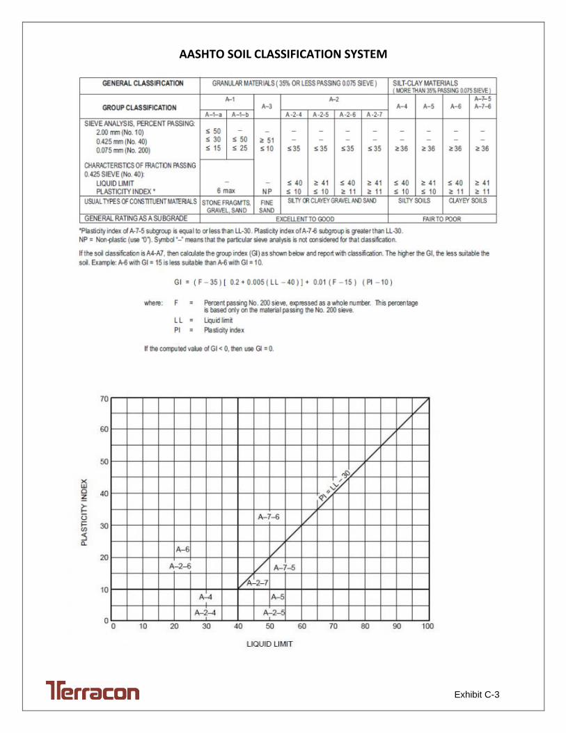
Exhibit C-3
AASHTO SOIL CLASSIFICATION SYSTEM