Embed Size (px)
Citation preview
REPORT C OVER PAGE
Geotechnical Engineering Report __________________________________________________________________________
Baldemar Cano Canopy
San Juan, Texas
June 18, 2019
Terracon Project No. 88195081
Prepared for:
Pharr-San Juan-Alamo ISD
Pharr, Texas
Prepared by:
Terracon Consultants, Inc.
Pharr, Texas
Responsive ■ Resourceful ■ Reliable 1
REPORT TOPICS
INTRODUCTION ............................................................................................................. 1 SITE CONDITIONS ......................................................................................................... 1 PROJECT DESCRIPTION .............................................................................................. 2 GEOTECHNICAL CHARACTERIZATION ...................................................................... 2
GEOTECHNICAL OVERVIEW ....................................................................................... 3 EARTHWORK ................................................................................................................ 4 SHALLOW FOUNDATIONS ........................................................................................... 8 DEEP FOUNDATIONS ................................................................................................. 12 SEISMIC CONSIDERATIONS ...................................................................................... 13
GENERAL COMMENTS ............................................................................................... 13
Note: This report was originally delivered in a web-based format. Orange Bold text in the report indicates a referenced
section heading. The PDF version also includes hyperlinks which direct the reader to that section and clicking on the
GeoReport logo will bring you back to this page. For more interactive features, please view your project online at
client.terracon.com.
ATTACHMENTS
EXPLORATION AND TESTING PROCEDURES
SITE LOCATION AND EXPLORATION PLANS
EXPLORATION RESULTS
SUPPORTING INFORMATION
Note: Refer to each individual Attachment for a listing of contents.
Geotechnical Engineering Report
Baldemar Cano Canopy ■ San Juan, Texas
June 18, 2019 ■ Terracon Project No. 88195081
Responsive ■ Resourceful ■ Reliable i
REPORT SUMMARY
Topic 1 Overview Statement
2
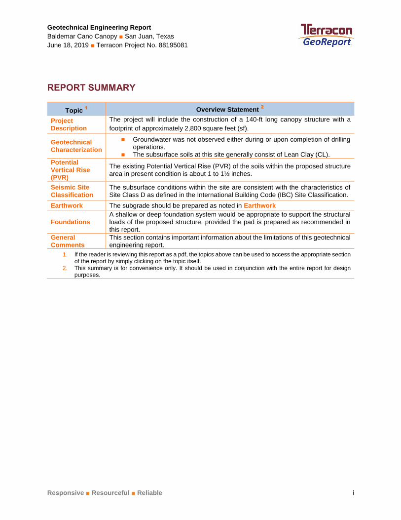
Project Description
The project will include the construction of a 140-ft long canopy structure with a
footprint of approximately 2,800 square feet (sf).
Geotechnical Characterization
◼ Groundwater was not observed either during or upon completion of drilling operations.
◼ The subsurface soils at this site generally consist of Lean Clay (CL).
Potential Vertical Rise (PVR)
The existing Potential Vertical Rise (PVR) of the soils within the proposed structure area in present condition is about 1 to 1½ inches.
Seismic Site Classification
The subsurface conditions within the site are consistent with the characteristics of Site Class D as defined in the International Building Code (IBC) Site Classification.
Earthwork The subgrade should be prepared as noted in Earthwork
Foundations A shallow or deep foundation system would be appropriate to support the structural loads of the proposed structure, provided the pad is prepared as recommended in this report.
General Comments
This section contains important information about the limitations of this geotechnical engineering report.
1. If the reader is reviewing this report as a pdf, the topics above can be used to access the appropriate section of the report by simply clicking on the topic itself.
2. This summary is for convenience only. It should be used in conjunction with the entire report for design purposes.
Responsive ■ Resourceful ■ Reliable 1
INTRODUCTION
Geotechnical Engineering Report
Baldemar Cano Canopy
800 S. Stewart Road
San Juan, Texas Terracon Project No. 88195081
June 18, 2019
INTRODUCTION This report presents the results of our subsurface exploration and geotechnical engineering
services performed for the proposed Baldemar Cano Canopy to be located at 800 S. Stewart
Road in San Juan, Texas. The purpose of these services is to provide information and
geotechnical engineering recommendations relative to:
■ Subsurface soil conditions
■ Groundwater conditions
■ Site preparation and earthwork
■ Excavation considerations
■ Foundation design and construction
■ Seismic site classification per IBC
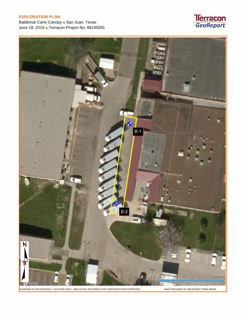
The geotechnical engineering Scope of Services for this project included the advancement of 2
test borings to of approximately 30 feet below existing site grades.
Maps showing the site and boring locations are presented in the Site Location and Exploration
Plan sections, respectively. The results of the laboratory testing performed on soil samples
obtained from the site during the field exploration are included on the boring logs in the
Exploration Results section.
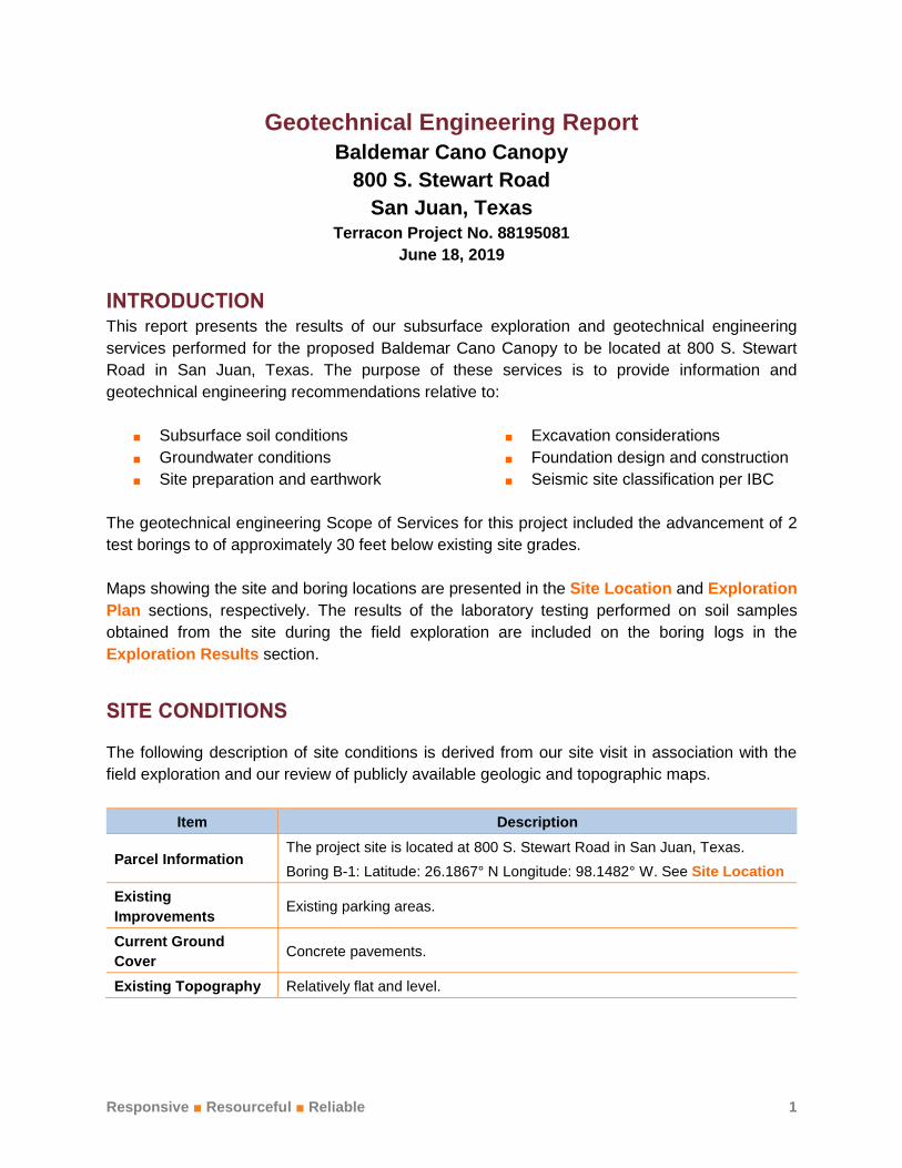
SITE CONDITIONS
The following description of site conditions is derived from our site visit in association with the
field exploration and our review of publicly available geologic and topographic maps.
Item Description
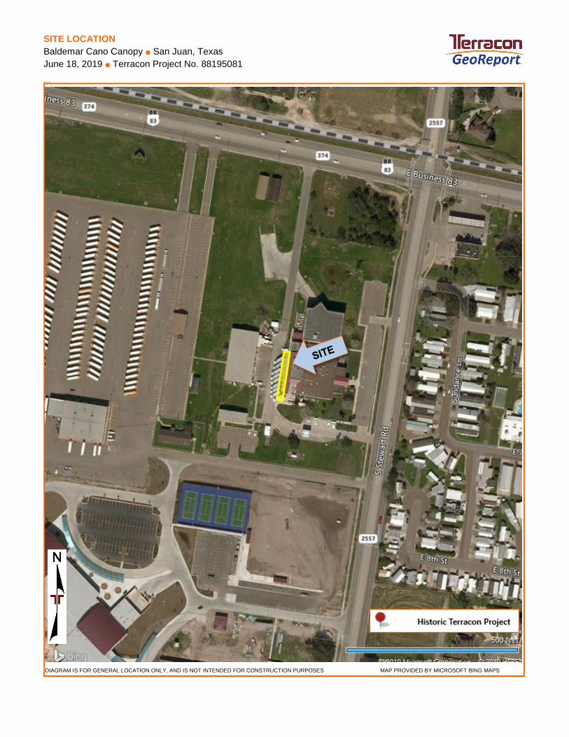
Parcel Information The project site is located at 800 S. Stewart Road in San Juan, Texas.
Boring B-1: Latitude: 26.1867° N Longitude: 98.1482° W. See Site Location
Existing
Improvements Existing parking areas.
Current Ground
Cover Concrete pavements.
Existing Topography Relatively flat and level.
Geotechnical Engineering Report
Baldemar Cano Canopy ■ San Juan, Texas
June 18, 2019 ■ Terracon Project No. 88195081
Responsive ■ Resourceful ■ Reliable 2
Item Description
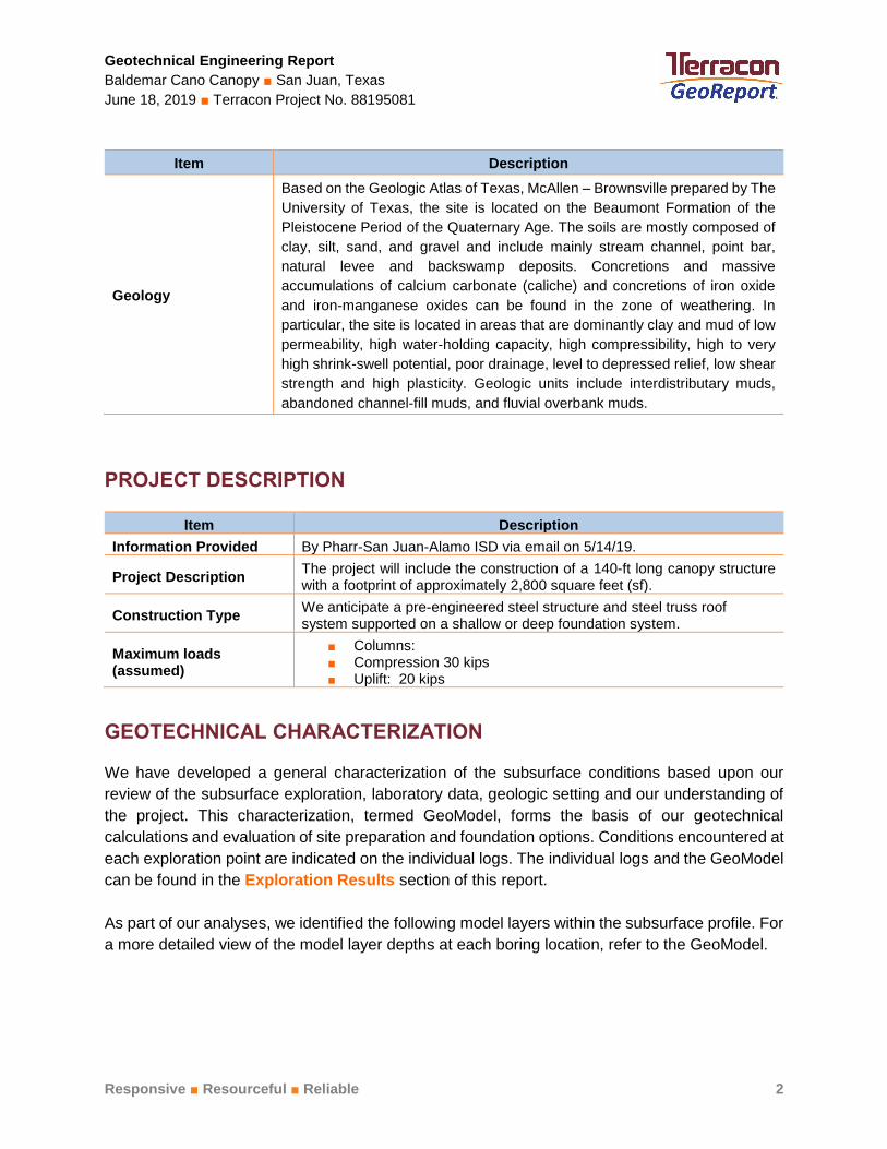
Geology
Based on the Geologic Atlas of Texas, McAllen – Brownsville prepared by The
University of Texas, the site is located on the Beaumont Formation of the
Pleistocene Period of the Quaternary Age. The soils are mostly composed of
clay, silt, sand, and gravel and include mainly stream channel, point bar,
natural levee and backswamp deposits. Concretions and massive
accumulations of calcium carbonate (caliche) and concretions of iron oxide
and iron-manganese oxides can be found in the zone of weathering. In
particular, the site is located in areas that are dominantly clay and mud of low
permeability, high water-holding capacity, high compressibility, high to very
high shrink-swell potential, poor drainage, level to depressed relief, low shear
strength and high plasticity. Geologic units include interdistributary muds,
abandoned channel-fill muds, and fluvial overbank muds.
PROJECT DESCRIPTION
Item Description
Information Provided By Pharr-San Juan-Alamo ISD via email on 5/14/19.
Project Description The project will include the construction of a 140-ft long canopy structure with a footprint of approximately 2,800 square feet (sf).
Construction Type We anticipate a pre-engineered steel structure and steel truss roof system supported on a shallow or deep foundation system.
Maximum loads (assumed)
■ Columns: ■ Compression 30 kips ■ Uplift: 20 kips
GEOTECHNICAL CHARACTERIZATION
We have developed a general characterization of the subsurface conditions based upon our
review of the subsurface exploration, laboratory data, geologic setting and our understanding of
the project. This characterization, termed GeoModel, forms the basis of our geotechnical
calculations and evaluation of site preparation and foundation options. Conditions encountered at
each exploration point are indicated on the individual logs. The individual logs and the GeoModel
can be found in the Exploration Results section of this report.
As part of our analyses, we identified the following model layers within the subsurface profile. For
a more detailed view of the model layer depths at each boring location, refer to the GeoModel.
Geotechnical Engineering Report
Baldemar Cano Canopy ■ San Juan, Texas
June 18, 2019 ■ Terracon Project No. 88195081
Responsive ■ Resourceful ■ Reliable 3
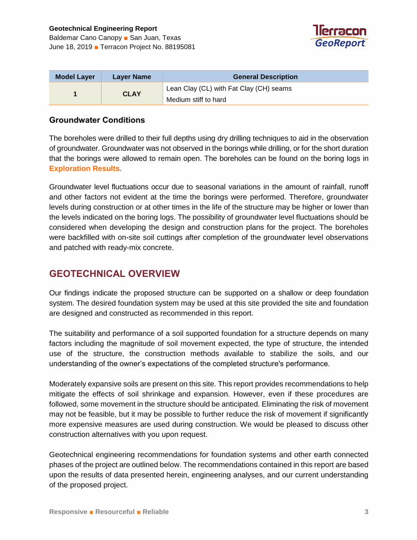
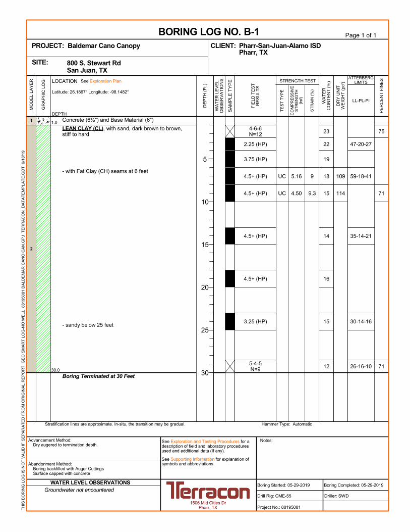
Model Layer Layer Name General Description
1 CLAY Lean Clay (CL) with Fat Clay (CH) seams
Medium stiff to hard
Groundwater Conditions
The boreholes were drilled to their full depths using dry drilling techniques to aid in the observation
of groundwater. Groundwater was not observed in the borings while drilling, or for the short duration
that the borings were allowed to remain open. The boreholes can be found on the boring logs in
Exploration Results.
Groundwater level fluctuations occur due to seasonal variations in the amount of rainfall, runoff
and other factors not evident at the time the borings were performed. Therefore, groundwater
levels during construction or at other times in the life of the structure may be higher or lower than
the levels indicated on the boring logs. The possibility of groundwater level fluctuations should be
considered when developing the design and construction plans for the project. The boreholes
were backfilled with on-site soil cuttings after completion of the groundwater level observations
and patched with ready-mix concrete.
GEOTECHNICAL OVERVIEW
Our findings indicate the proposed structure can be supported on a shallow or deep foundation
system. The desired foundation system may be used at this site provided the site and foundation
are designed and constructed as recommended in this report.
The suitability and performance of a soil supported foundation for a structure depends on many
factors including the magnitude of soil movement expected, the type of structure, the intended
use of the structure, the construction methods available to stabilize the soils, and our
understanding of the owner’s expectations of the completed structure's performance.
Moderately expansive soils are present on this site. This report provides recommendations to help
mitigate the effects of soil shrinkage and expansion. However, even if these procedures are
followed, some movement in the structure should be anticipated. Eliminating the risk of movement
may not be feasible, but it may be possible to further reduce the risk of movement if significantly
more expensive measures are used during construction. We would be pleased to discuss other
construction alternatives with you upon request.
Geotechnical engineering recommendations for foundation systems and other earth connected
phases of the project are outlined below. The recommendations contained in this report are based
upon the results of data presented herein, engineering analyses, and our current understanding
of the proposed project.
Geotechnical Engineering Report
Baldemar Cano Canopy ■ San Juan, Texas
June 18, 2019 ■ Terracon Project No. 88195081
Responsive ■ Resourceful ■ Reliable 4
The General Comments section provides an understanding of the report limitations.
Swell Test Results
Swell tests were performed on soil samples from the boring drilled at the site. After surcharge
pressures were applied the samples were inundated with water for about 72 to 96 hours while
measurements of vertical displacement were taken. The magnitude of swell is recorded as a
function of the change in thickness during the test in relation to the initial thickness of the sample.
Based on our laboratory results, the samples tested generally exhibit a low free swell potential as
indicated by percent free swells of 0.7 percent within the top 4 feet. When equivalent overburden
pressure was applied, the resulting swell was 0.1 percent.
EARTHWORK
Earthwork will include clearing and grubbing, excavations and fill placement. The following
sections provide recommendations for use in the preparation of specifications for the work.
Recommendations include critical quality criteria as necessary to render the site in the state
considered in our geotechnical engineering evaluation for foundations and pavements.
Site Preparation
Construction areas should be stripped of all vegetation, pavements, topsoil and other unsuitable
material. Additional excavation as recommended in this report or as needed should be performed
within the proposed structure area. Once final subgrade elevation has been achieved, the
exposed subgrade should be carefully proofrolled with a 15-ton pneumatic roller or a fully loaded
dump truck to detect weak zones in the subgrade. Special care should be exercised when
proofrolling the fill soils to detect soft/weak areas. Weak areas detected during proofrolling, as
well as zones of fill containing organic matter and/or debris should be removed and replaced with
select fill in the proposed structure area. Proper site drainage should be maintained during
construction, so that ponding of surface runoff does not occur and cause construction delays
and/or inhibit site access.
Subsequent to proofrolling, and just prior to placement of fill, the exposed subgrade within the
construction area should be evaluated for moisture and density. If the moisture, density, and/or
the requirements do not meet the criteria described in the table below, the subgrade should be
scarified to a minimum depth of 8 inches, moisture adjusted and compacted to at least 95 percent
of the Standard Effort (ASTM D 698) maximum dry density. Select fill should meet the following
criteria.
Geotechnical Engineering Report
Baldemar Cano Canopy ■ San Juan, Texas
June 18, 2019 ■ Terracon Project No. 88195081
Responsive ■ Resourceful ■ Reliable 5
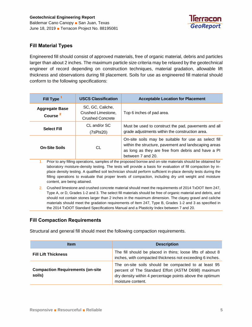
Fill Material Types
Engineered fill should consist of approved materials, free of organic material, debris and particles
larger than about 2 inches. The maximum particle size criteria may be relaxed by the geotechnical
engineer of record depending on construction techniques, material gradation, allowable lift
thickness and observations during fill placement. Soils for use as engineered fill material should
conform to the following specifications:
Fill Compaction Requirements
Structural and general fill should meet the following compaction requirements.
Item Description
Fill Lift Thickness The fill should be placed in thins; loose lifts of about 8
inches, with compacted thickness not exceeding 6 inches.
Compaction Requirements (on-site
soils)
The on-site soils should be compacted to at least 95
percent of The Standard Effort (ASTM D698) maximum
dry density within 4 percentage points above the optimum
moisture content.
Fill Type 1
USCS Classification Acceptable Location for Placement
Aggregate Base
Course 2
SC, GC, Caliche,
Crushed Limestone,
Crushed Concrete
Top 6 inches of pad area.
Select Fill CL and/or SC
(7≤PI≤20)
Must be used to construct the pad, pavements and all
grade adjustments within the construction area.
On-Site Soils CL
On-site soils may be suitable for use as select fill
within the structure, pavement and landscaping areas
as long as they are free from debris and have a PI
between 7 and 20.
1. Prior to any filling operations, samples of the proposed borrow and on-site materials should be obtained for
laboratory moisture-density testing. The tests will provide a basis for evaluation of fill compaction by in-
place density testing. A qualified soil technician should perform sufficient in-place density tests during the
filling operations to evaluate that proper levels of compaction, including dry unit weight and moisture
content, are being attained.
2. Crushed limestone and crushed concrete material should meet the requirements of 2014 TxDOT Item 247,
Type A, or D, Grades 1-2 and 3. The select fill materials should be free of organic material and debris, and
should not contain stones larger than 2 inches in the maximum dimension. The clayey gravel and caliche
materials should meet the gradation requirements of Item 247, Type B, Grades 1-2 and 3 as specified in
the 2014 TxDOT Standard Specifications Manual and a Plasticity Index between 7 and 20.
Geotechnical Engineering Report
Baldemar Cano Canopy ■ San Juan, Texas
June 18, 2019 ■ Terracon Project No. 88195081
Responsive ■ Resourceful ■ Reliable 6
Item Description
Compaction Requirements (select fill)
The select fill should be compacted to at least 95 percent
of The Standard Effort (ASTM D698) maximum dry density
within 2 percentage points of the optimum moisture
content.
Wet Weather/Soft Subgrade Conditions
Construction operations may encounter difficulties due to the wet or soft surface soils becoming
a general hindrance to equipment due to rutting and pumping of the soil surface, especially during
and soon after periods of wet weather. If the subgrade cannot be adequately compacted to
minimum densities as described above, one of the following measures will be required: 1) removal
and replacement with select fill, 2) chemical treatment of the soil to dry and increase the stability
of the subgrade, or 3) drying by natural means if the schedule allows. In our experience with
similar soils in this area, chemical treatment is the most efficient and effective method to increase
the supporting value of wet and weak subgrade. Terracon should be contacted for additional
recommendations if chemical treatment of the soils is needed.
Prior to placing any fill, all surface vegetation, topsoil and any otherwise unsuitable materials
should be removed from the construction areas. Wet or dry material should either be removed or
moisture conditioned and recompacted. After stripping and grubbing, the subgrade should be
proof-rolled where possible to aid in locating loose or soft areas. Proof-rolling can be performed
with a 20-ton roller or fully loaded dump truck. Soft, dry and low-density soil should be removed
or compacted in place prior to placing fill.
Grading and Drainage
All grades must provide effective drainage away from the canopy area during and after
construction. Water permitted to pond next to the structure can result in distress in the structure.
These greater movements can result in unacceptable differential floor slab movements, cracked
slabs and walls, and roof leaks.
Foundation performances described in this report are based on effective drainage for the life of
the structure and cannot be relied upon if effective drainage is not maintained. Exposed ground
should be sloped away from the structure for at least 10 feet beyond the perimeter of the structure.
After construction and landscaping, we recommend verifying final grades to document that
effective drainage has been achieved. Grades around the structures should also be periodically
inspected and adjusted as necessary, as part of the structure's maintenance program.
Locate sprinkler mains and spray heads a minimum of 5 feet away from the structure lines. Low-
volume, drip style landscaped irrigation should not be used near the proposed structure. Collect
Geotechnical Engineering Report
Baldemar Cano Canopy ■ San Juan, Texas
June 18, 2019 ■ Terracon Project No. 88195081
Responsive ■ Resourceful ■ Reliable 7
roof runoff in drains or gutters. Discharge roof drains and downspouts onto pavements and/or
flatworks which slope away from the structures or extend down spouts a minimum of 10 feet away
from structures.
Flatworks will be subject to post construction movement. Maximum grades practical should be
used for flatwork to prevent water from ponding. Allowances in final grades should also consider
post-construction movement of flatwork, particularly if such movement would be critical. Where
paving or flatwork abuts the structure, effectively seal and maintain joints to prevent surface water
infiltration.
Utility trenches are a common source of water infiltration and migration. All utility trenches that
penetrate beneath the structure should be effectively sealed to restrict water intrusion and flow
through the trenches that could migrate below the structure. We recommend constructing an
effective clay “trench plug” that extends at least 5 feet out from the face of the structure exterior.
The plug material should consist of clay compacted at a water content at or above the soils
optimum water content. The clay fill should be placed to completely surround the utility line and
be compacted in accordance with recommendations in this report.
Earthwork Construction Considerations
Shallow excavations, for the proposed structure, are anticipated to be accomplished with
conventional construction equipment. Upon completion of filling and grading, care should be taken
to maintain the subgrade water content prior to construction of floor slabs. Construction traffic
over the completed subgrades should be avoided. The site should also be graded to prevent
ponding of surface water on the prepared subgrades or in excavations. Water collecting over, or
adjacent to construction area should be removed. If the subgrade freezes, desiccates, saturates,
or is disturbed, the affected material should be removed, or the materials should be scarified,
moisture conditioned, and recompacted, prior to floor slab construction.
As a minimum, excavations should be performed in accordance with OSHA 29 CFR, Part 1926,
Subpart P, “Excavations” and its appendices, and in accordance with any applicable local, and/or
state regulations.
Construction site safety is the sole responsibility of the contractor who controls the means,
methods, and sequencing of construction operations. Under no circumstances shall the
information provided herein be interpreted to mean Terracon is assuming responsibility for
construction site safety, or the contractor's activities; such responsibility shall neither be implied
nor inferred.
Geotechnical Engineering Report
Baldemar Cano Canopy ■ San Juan, Texas
June 18, 2019 ■ Terracon Project No. 88195081
Responsive ■ Resourceful ■ Reliable 8
Construction Observation and Testing
The earthwork efforts should be monitored under the direction of the Geotechnical Engineer.
Monitoring should include documentation of adequate removal of vegetation and top soil, proof-
rolling and mitigation of areas delineated by the proof-roll to require mitigation.
Each lift of compacted fill should be tested, evaluated, and reworked as necessary until approved
by the Geotechnical Engineer prior to placement of additional lifts. Each lift of fill should be tested
for density and water content at a frequency of at least one test for every 2,500 square feet of
compacted fill in the structure area and 5,000 square feet in pavement areas. One density and
water content test for every 50 linear feet of compacted utility trench backfill.
In areas of foundation excavations, the bearing subgrade should be evaluated under the direction
of the Geotechnical Engineer. In the event unanticipated conditions are encountered, the
Geotechnical Engineer should prescribe mitigation options.
In addition to the documentation of the essential parameters necessary for construction, the
continuation of the Geotechnical Engineer into the construction phase of the project provides the
continuity to maintain the Geotechnical Engineer’s evaluation of subsurface conditions, including
assessing variations and associated design changes.
SHALLOW FOUNDATIONS
If the site has been prepared in accordance with the requirements noted in Earthwork, the
following design parameters are applicable for shallow foundations.
Design Recommendations – Spread Footing Foundation
Spread footings may be considered in the design of the foundations to support the main column
loads. Lateral loads transmitted to the footings should be resisted by a combination of soil-
concrete friction on the base of the footing and passive pressure on the side of the footing. To
resist lateral forces, a net allowable passive resistance may be utilized for portions of footings
extending at least 30 inches below finished grade. If the footing is formed during construction, the
open space between the footing and the in-situ soils should be backfilled with soils. Also, care
should be taken to avoid disturbance of the footing bearing area since loose material could
increase settlement and decrease resistance to lateral loading.
The spread footings can provide some uplift resistance for those structures subjected to wind or
other induced structural loading.
Geotechnical Engineering Report
Baldemar Cano Canopy ■ San Juan, Texas
June 18, 2019 ■ Terracon Project No. 88195081
Responsive ■ Resourceful ■ Reliable 9
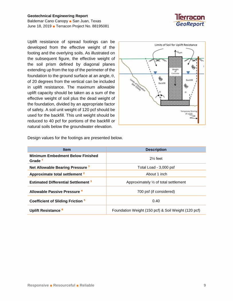
Uplift resistance of spread footings can be
developed from the effective weight of the
footing and the overlying soils. As illustrated on
the subsequent figure, the effective weight of
the soil prism defined by diagonal planes
extending up from the top of the perimeter of the
foundation to the ground surface at an angle, ,
of 20 degrees from the vertical can be included
in uplift resistance. The maximum allowable
uplift capacity should be taken as a sum of the
effective weight of soil plus the dead weight of
the foundation, divided by an appropriate factor
of safety. A soil unit weight of 120 pcf should be
used for the backfill. This unit weight should be
reduced to 40 pcf for portions of the backfill or
natural soils below the groundwater elevation.
Design values for the footings are presented below.
Item Description
Minimum Embedment Below Finished
Grade 1 2½ feet
Net Allowable Bearing Pressure 7 Total Load - 3,000 psf
Approximate total settlement 2 About 1 inch
Estimated Differential Settlement 3 Approximately ½ of total settlement
Allowable Passive Pressure 4 700 psf (if considered)
Coefficient of Sliding Friction 5 0.40
Uplift Resistance 6 Foundation Weight (150 pcf) & Soil Weight (120 pcf)
Geotechnical Engineering Report
Baldemar Cano Canopy ■ San Juan, Texas
June 18, 2019 ■ Terracon Project No. 88195081
Responsive ■ Resourceful ■ Reliable 10
Item Description
1. To bear within the native soils or select fill.
2. This estimated post-construction settlement of the shallow footings is without considering the effect of stress distribution from adjacent foundations and assuming proper construction practices are followed. A clear distance between the footings of one footing size should not produce overlapping stress distributions and would essentially behave as independent foundations.
3. Differential settlement may result from variances in subsurface conditions, loading conditions and construction procedures. The settlement response of the footings will be more dependent upon the quality of construction than upon the response of the subgrade to the foundation loads. We estimate that the differential settlement should be approximately one-half of the total settlement. Settlement of footings will be more sensitive to installation techniques than to soil-structure interaction.
4. The passive pressure along the exterior of the footings should be neglected unless pavement is provided up to the edge of the structure. For interior footings, the allowable passive pressure may be used for the entire depth of the footing. The passive pressure provided above includes a factor of safety of at least 3.
5. Lateral loads transmitted to the footings will be resisted by a combination of soil-concrete friction on the base of the footings and passive pressure on the side of the footings.
6. The ultimate uplift capacity of shallow footings should be reduced by an appropriate factor of safety to compute allowable uplift capacity.
7. The net allowable bearing pressure provided above include a factor of safety of at least 2.
Construction Considerations for Spread Footing Foundations
As noted in Earthwork, the footing excavations should be evaluated under the direction of the
Geotechnical Engineer. The base of all foundation excavations should be free of water and loose
soil, prior to placing concrete. Concrete should be placed soon after excavating to reduce bearing
soil disturbance. Care should be taken to prevent wetting or drying of the bearing materials during
construction. Excessively wet or dry material or any loose/disturbed material in the bottom of the
footing excavations should be removed/reconditioned before foundation concrete is placed. Due
to the presence of dry soils, caving of excavation may occur. Therefore, the foundation contractor
should be prepared to use forms.
Excavation should be accomplished with a smooth-mouthed bucket. If a toothed bucket is used,
excavation with this bucket should be stopped 6 inches above the final bearing surface and the
excavation completed with a smooth-mouthed bucket or by hand labor.
If the footing foundations are over-excavated and formed, the backfill around the foundation sides
should be achieved with compacted select fill, lean concrete, compacted cement stabilized sand
(two sacks cement to one cubic yard of sand) or flowable fill. Compaction of select fill should be
as described later in this section of the report.
The bearing surface should be excavated with a slight slope to create an internal sump for runoff
water collection and removal. If surface runoff water in excess of 2 inches accumulates at the
bottom of the excavation, it should be pumped out prior to concrete placement. Under no
circumstances should water be allowed to adversely affect the quality of the bearing surface. If
the spread footing is buried, backfill above the foundation may be the excavated on-site soils or
Geotechnical Engineering Report
Baldemar Cano Canopy ■ San Juan, Texas
June 18, 2019 ■ Terracon Project No. 88195081
Responsive ■ Resourceful ■ Reliable 11
select fill soils. Backfill soils should be compacted to at least 95 percent of the maximum dry
density as determined by the standard moisture/density relationship test (ASTM D 698). Moisture
contents for on-site soils and imported select fill soils should be within 2 percentage points of the
optimum moisture content. The backfill should be placed in thin, loose lifts of about 8 inches, with
compacted thickness not to exceed 6 inches.
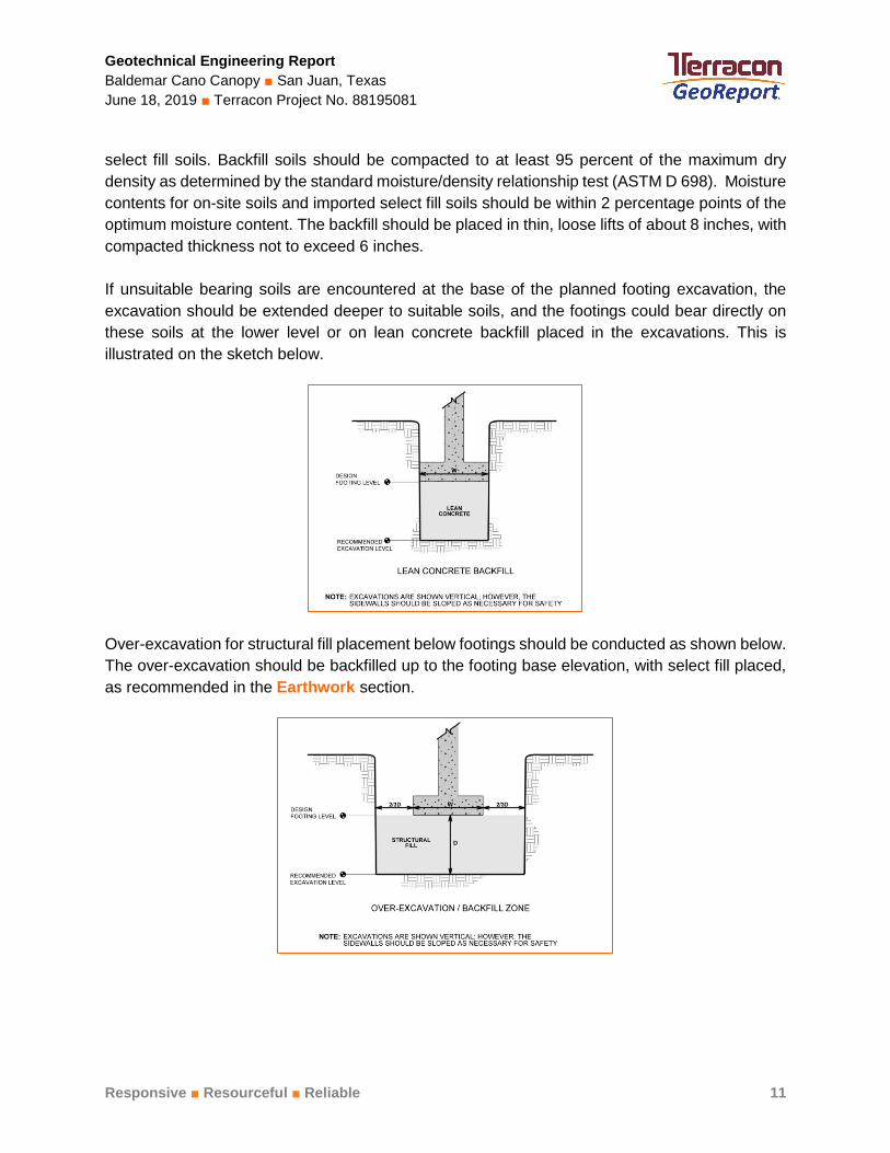
If unsuitable bearing soils are encountered at the base of the planned footing excavation, the
excavation should be extended deeper to suitable soils, and the footings could bear directly on
these soils at the lower level or on lean concrete backfill placed in the excavations. This is
illustrated on the sketch below.
Over-excavation for structural fill placement below footings should be conducted as shown below.
The over-excavation should be backfilled up to the footing base elevation, with select fill placed,
as recommended in the Earthwork section.
Geotechnical Engineering Report
Baldemar Cano Canopy ■ San Juan, Texas
June 18, 2019 ■ Terracon Project No. 88195081
Responsive ■ Resourceful ■ Reliable 12
DEEP FOUNDATIONS
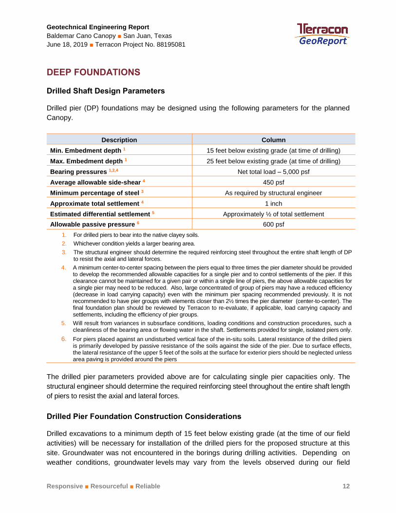
Drilled Shaft Design Parameters
Drilled pier (DP) foundations may be designed using the following parameters for the planned
Canopy.
Description Column
Min. Embedment depth 1 15 feet below existing grade (at time of drilling)
Max. Embedment depth 1 25 feet below existing grade (at time of drilling)
Bearing pressures 1,2,4 Net total load – 5,000 psf
Average allowable side-shear 4 450 psf
Minimum percentage of steel 3 As required by structural engineer
Approximate total settlement 4 1 inch
Estimated differential settlement 5 Approximately ½ of total settlement
Allowable passive pressure 6 600 psf
1. For drilled piers to bear into the native clayey soils.
2. Whichever condition yields a larger bearing area.
3. The structural engineer should determine the required reinforcing steel throughout the entire shaft length of DP to resist the axial and lateral forces.
4. A minimum center-to-center spacing between the piers equal to three times the pier diameter should be provided to develop the recommended allowable capacities for a single pier and to control settlements of the pier. If this clearance cannot be maintained for a given pair or within a single line of piers, the above allowable capacities for a single pier may need to be reduced. Also, large concentrated of group of piers may have a reduced efficiency (decrease in load carrying capacity) even with the minimum pier spacing recommended previously. It is not recommended to have pier groups with elements closer than 2½ times the pier diameter (center-to-center). The final foundation plan should be reviewed by Terracon to re-evaluate, if applicable, load carrying capacity and settlements, including the efficiency of pier groups.
5. Will result from variances in subsurface conditions, loading conditions and construction procedures, such a cleanliness of the bearing area or flowing water in the shaft. Settlements provided for single, isolated piers only.
6. For piers placed against an undisturbed vertical face of the in-situ soils. Lateral resistance of the drilled piers is primarily developed by passive resistance of the soils against the side of the pier. Due to surface effects, the lateral resistance of the upper 5 feet of the soils at the surface for exterior piers should be neglected unless area paving is provided around the piers
The drilled pier parameters provided above are for calculating single pier capacities only. The
structural engineer should determine the required reinforcing steel throughout the entire shaft length
of piers to resist the axial and lateral forces.
Drilled Pier Foundation Construction Considerations
Drilled excavations to a minimum depth of 15 feet below existing grade (at the time of our field
activities) will be necessary for installation of the drilled piers for the proposed structure at this
site. Groundwater was not encountered in the borings during drilling activities. Depending on
weather conditions, groundwater levels may vary from the levels observed during our field
Geotechnical Engineering Report
Baldemar Cano Canopy ■ San Juan, Texas
June 18, 2019 ■ Terracon Project No. 88195081
Responsive ■ Resourceful ■ Reliable 13
program. Water must not be allowed to accumulate in the bottom of the pier excavations.
Preferably, pier excavations should be backfilled with concrete within about 2 to 4 hours of
completion of the drilling and in no case should an excavation be left open overnight. The concrete
placed in the excavations should have a 6-inch slump with a plus or minus one inch tolerance.
The bottom of pier footing excavation should be free of all loose materials and/or water, and
the bearing surface should be evaluated immediately prior to placing concrete.
Foundation Construction Monitoring
The performance of the foundation system for the proposed structure will be highly dependent
upon the quality of construction. Thus, we recommend that fill pad compaction and foundation
installation be monitored full time by an experienced Terracon soil technician under the direction
of our Geotechnical Engineer.
During foundation installation, the base should be monitored to evaluate the condition of the
subgrade. We would be pleased to develop a plan for compaction and foundation installation
monitoring to be incorporated in the overall quality control program.
SEISMIC CONSIDERATIONS
The seismic design requirements for buildings and other structures are based on Seismic Design
Category. Site Classification is required to determine the Seismic Design Category for a structure.
The Site Classification is based on the upper 100 feet of the site profile defined by a weighted
average value of either shear wave velocity, standard penetration resistance, or undrained shear
strength in accordance with Section 20.4 of ASCE 7 and the International Building Code (IBC).
Based on the soil properties encountered at the site and as described on the exploration logs and
results, it is our professional opinion that the Seismic Site Classification is D. Subsurface
explorations at this site were extended to a maximum depth of 30 feet. The site properties below
the boring depth to 100 feet were estimated based on our experience and knowledge of geologic
conditions of the general area. Additional deeper borings or geophysical testing may be performed
to confirm the conditions below the current boring depth.
GENERAL COMMENTS
Our analysis and opinions are based upon our understanding of the project, the geotechnical
conditions in the area, and the data obtained from our site exploration. Natural variations will occur
between exploration point locations or due to the modifying effects of construction or weather.
The nature and extent of such variations may not become evident until during or after construction.
Terracon should be retained as the Geotechnical Engineer, where noted in this report, to provide
Geotechnical Engineering Report
Baldemar Cano Canopy ■ San Juan, Texas
June 18, 2019 ■ Terracon Project No. 88195081
Responsive ■ Resourceful ■ Reliable 14
observation and testing services during pertinent construction phases. If variations appear, we
can provide further evaluation and supplemental recommendations. If variations are noted in the
absence of our observation and testing services on-site, we should be immediately notified so
that we can provide evaluation and supplemental recommendations.
Our Scope of Services does not include either specifically or by implication any environmental or
biological (e.g., mold, fungi, bacteria) assessment of the site or identification or prevention of
pollutants, hazardous materials or conditions. If the owner is concerned about the potential for
such contamination or pollution, other studies should be undertaken.
Our services and any correspondence or collaboration through this system are intended for the
sole benefit and exclusive use of our client for specific application to the project discussed and
are accomplished in accordance with generally accepted geotechnical engineering practices with
no third-party beneficiaries intended. Any third-party access to services or correspondence is
solely for information purposes to support the services provided by Terracon to our client.
Reliance upon the services and any work product is limited to our client, and is not intended for
third parties. Any use or reliance of the provided information by third parties is done solely at their
own risk. No warranties, either express or implied, are intended or made.
Site characteristics as provided are for design purposes and not to estimate excavation cost. Any
use of our report in that regard is done at the sole risk of the excavating cost estimator as there
may be variations on the site that are not apparent in the data that could significantly impact
excavation cost. Any parties charged with estimating excavation costs should seek their own site
characterization for specific purposes to obtain the specific level of detail necessary for costing.
Site safety, and cost estimating including, excavation support, and dewatering
requirements/design are the responsibility of others. If changes in the nature, design, or location
of the project are planned, our conclusions and recommendations shall not be considered valid
unless we review the changes and either verify or modify our conclusions in writing.

Responsive ■ Resourceful ■ Reliable
ATTACHMENTS
Geotechnical Engineering Report
Baldemar Cano Canopy ■ San Juan, Texas
June 18, 2019 ■ Terracon Project No. 88195081
Responsive ■ Resourceful ■ Reliable EXPLORATION AND TESTING PROCEDURES 1 of 2
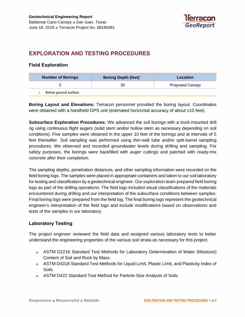
EXPLORATION AND TESTING PROCEDURES
Field Exploration
Number of Borings Boring Depth (feet) 1 Location
2 30 Proposed Canopy
1. Below ground surface
Boring Layout and Elevations: Terracon personnel provided the boring layout. Coordinates
were obtained with a handheld GPS unit (estimated horizontal accuracy of about ±10 feet).
Subsurface Exploration Procedures: We advanced the soil borings with a truck-mounted drill
rig using continuous flight augers (solid stem and/or hollow stem as necessary depending on soil
conditions). Five samples were obtained in the upper 10 feet of the borings and at intervals of 5
feet thereafter. Soil sampling was performed using thin-wall tube and/or split-barrel sampling
procedures. We observed and recorded groundwater levels during drilling and sampling. For
safety purposes, the borings were backfilled with auger cuttings and patched with ready-mix
concrete after their completion.
The sampling depths, penetration distances, and other sampling information were recorded on the
field boring logs. The samples were placed in appropriate containers and taken to our soil laboratory
for testing and classification by a geotechnical engineer. Our exploration team prepared field boring
logs as part of the drilling operations. The field logs included visual classifications of the materials
encountered during drilling and our interpretation of the subsurface conditions between samples.
Final boring logs were prepared from the field log. The final boring logs represent the geotechnical
engineer's interpretation of the field logs and include modifications based on observations and
tests of the samples in our laboratory.
Laboratory Testing
The project engineer reviewed the field data and assigned various laboratory tests to better
understand the engineering properties of the various soil strata as necessary for this project.
■ ASTM D2216 Standard Test Methods for Laboratory Determination of Water (Moisture)
Content of Soil and Rock by Mass
■ ASTM D4318 Standard Test Methods for Liquid Limit, Plastic Limit, and Plasticity Index of
Soils
■ ASTM D422 Standard Test Method for Particle-Size Analysis of Soils
Geotechnical Engineering Report
Baldemar Cano Canopy ■ San Juan, Texas
June 18, 2019 ■ Terracon Project No. 88195081
Responsive ■ Resourceful ■ Reliable EXPLORATION AND TESTING PROCEDURES 2 of 2
■ ASTM D2166/D2166M Standard Test Method for Unconfined Compressive Strength of
Cohesive Soil
■ ASTM D4546 Standard Test Methods for One-Dimensional Swell or Collapse of Soils
The laboratory testing program often included examination of soil samples by an engineer. Based
on the material’s texture and plasticity, we described and classified the soil samples in accordance
with the Unified Soil Classification System (USCS).
Responsive ■ Resourceful ■ Reliable
SITE LOCATION AND EXPLORATION PLANS
Contents:
Site Location Plan
Exploration Plan
SITE LOCATION
Baldemar Cano Canopy ■ San Juan, Texas
June 18, 2019 ■ Terracon Project No. 88195081
Note to Preparer: This is a large table with outside borders. Just click inside the table
above this text box, then paste your GIS Toolbox image.
When paragraph markers are turned on you may notice a line of hidden text above and
outside the table – please leave that alone. Limit editing to inside the table.
The line at the bottom about the general location is a separate table line. You can edit
it as desired, but try to keep to a single line of text to avoid reformatting the page.
SITE LOC ATION
DIAGRAM IS FOR GENERAL LOCATION ONLY, AND IS NOT INTENDED FOR CONSTRUCTION PURPOSES MAP PROVIDED BY MICROSOFT BING MAPS
EXPLORATION PLAN
Baldemar Cano Canopy ■ San Juan, Texas
June 18, 2019 ■ Terracon Project No. 88195081
Note to Preparer: This is a large table with outside borders. Just click inside the table
above this text box, then paste your GIS Toolbox image.
When paragraph markers are turned on you may notice a line of hidden text above and
outside the table – please leave that alone. Limit editing to inside the table.
The line at the bottom about the general location is a separate table line. You can edit
it as desired, but try to keep to a single line of text to avoid reformatting the page.
EXPLOR ATION PLAN
DIAGRAM IS FOR GENERAL LOCATION ONLY, AND IS NOT INTENDED FOR CONSTRUCTION PURPOSES MAP PROVIDED BY MICROSOFT BING MAPS
EXPLORATION RESULTS
Contents:
Boring Logs
GeoModel
Note: All attachments are one page unless noted above.
4-6-6N=12
2.25 (HP)
3.75 (HP)
4.5+ (HP)
4.5+ (HP)
4.5+ (HP)
4.5+ (HP)
3.25 (HP)
5-4-5N=9
5.16
4.50
UC
UC
9
9.3
75
71
71
23
22
19
18
15
14
16
15
12
109
114
47-20-27
59-18-41
35-14-21
30-14-16
26-16-10
Concrete (6½") and Base Material (6")
LEAN CLAY (CL), with sand, dark brown to brown,stiff to hard
- with Fat Clay (CH) seams at 6 feet
- sandy below 25 feet
Boring Terminated at 30 Feet
1.0
30.0
Hammer Type: AutomaticStratification lines are approximate. In-situ, the transition may be gradual.
TH
IS B
OR
ING
LO
G IS
NO
T V
ALI
D IF
SE
PA
RA
TE
D F
RO
M O
RIG
INA
L R
EP
OR
T.
GE
O S
MA
RT
LO
G-N
O W
ELL
881
950
81 B
ALD
EM
AR
CA
NO
CA
N.G
PJ
TE
RR
AC
ON
_DA
TA
TE
MP
LAT
E.G
DT
6/1
8/1
9
WA
TE
R L
EV
EL
OB
SE
RV
AT
ION
S
DE
PT
H (
Ft.)
5
10
15
20
25
30
STRENGTH TEST
FIE
LD T
ES
TR
ES
ULT
S
CO
MP
RE
SS
IVE
ST
RE
NG
TH
(tsf
)
TE
ST
TY
PE
ST
RA
IN (
%)
PE
RC
EN
T F
INE
S
WA
TE
RC
ON
TE
NT
(%
)
DR
Y U
NIT
WE
IGH
T (
pcf)
ATTERBERGLIMITS
LL-PL-PI
LOCATION See Exploration Plan
Latitude: 26.1867° Longitude: -98.1482°
GR
AP
HIC
LO
G
MO
DE
L LA
YE
R
DEPTH
Page 1 of 1
Advancement Method:Dry augered to termination depth.
Abandonment Method:Boring backfilled with Auger CuttingsSurface capped with concrete
1506 Mid Cities DrPharr, TX
Notes:
Project No.: 88195081
Drill Rig: CME-55
BORING LOG NO. B-1Pharr-San-Juan-Alamo ISDCLIENT:Pharr, TX
Driller: SWD
Boring Completed: 05-29-2019
PROJECT: Baldemar Cano Canopy
See Exploration and Testing Procedures for adescription of field and laboratory proceduresused and additional data (If any).
See Supporting Information for explanation ofsymbols and abbreviations.
800 S. Stewart Rd San Juan, TXSITE:
Boring Started: 05-29-2019WATER LEVEL OBSERVATIONSGroundwater not encountered
1
2
SA
MP
LE T
YP
E
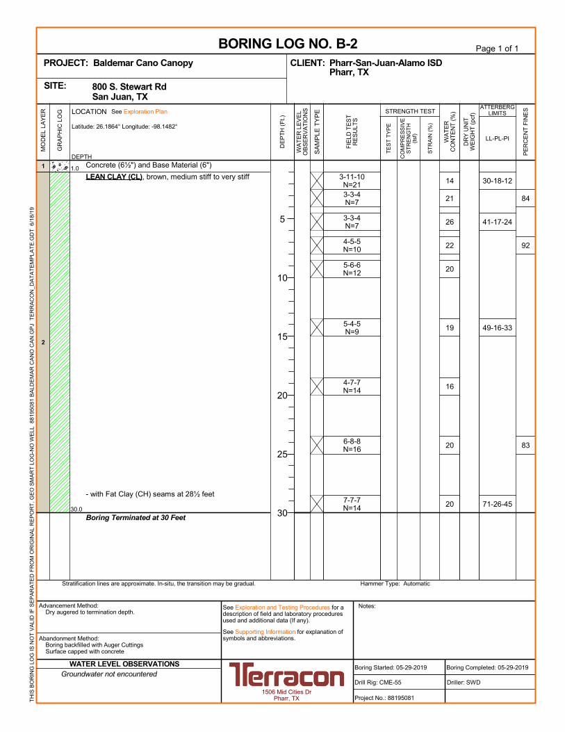
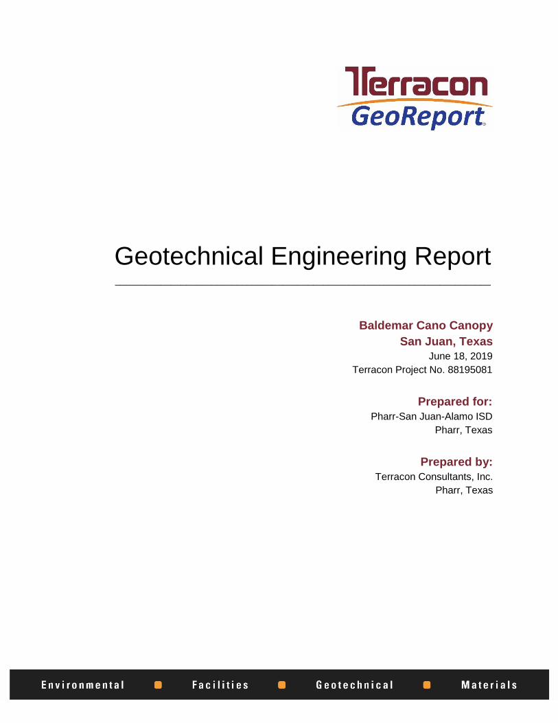
3-11-10N=213-3-4N=7
3-3-4N=7
4-5-5N=10
5-6-6N=12
5-4-5N=9
4-7-7N=14
6-8-8N=16
7-7-7N=14
84
92
83
14
21
26
22
20
19
16
20
20
30-18-12
41-17-24
49-16-33
71-26-45
Concrete (6½") and Base Material (6")
LEAN CLAY (CL), brown, medium stiff to very stiff
- with Fat Clay (CH) seams at 28½ feet
Boring Terminated at 30 Feet
1.0
30.0
Hammer Type: AutomaticStratification lines are approximate. In-situ, the transition may be gradual.
TH
IS B
OR
ING
LO
G IS
NO
T V
ALI
D IF
SE
PA
RA
TE
D F
RO
M O
RIG
INA
L R
EP
OR
T.
GE
O S
MA
RT
LO
G-N
O W
ELL
881
950
81 B
ALD
EM
AR
CA
NO
CA
N.G
PJ
TE
RR
AC
ON
_DA
TA
TE
MP
LAT
E.G
DT
6/1
8/1
9
WA
TE
R L
EV
EL
OB
SE
RV
AT
ION
S
DE
PT
H (
Ft.)
5
10
15
20
25
30
STRENGTH TEST
FIE
LD T
ES
TR
ES
ULT
S
CO
MP
RE
SS
IVE
ST
RE
NG
TH
(tsf
)
TE
ST
TY
PE
ST
RA
IN (
%)
PE
RC
EN
T F
INE
S
WA
TE
RC
ON
TE
NT
(%
)
DR
Y U
NIT
WE
IGH
T (
pcf)
ATTERBERGLIMITS
LL-PL-PI
LOCATION See Exploration Plan
Latitude: 26.1864° Longitude: -98.1482°
GR
AP
HIC
LO
G
MO
DE
L LA
YE
R
DEPTH
Page 1 of 1
Advancement Method:Dry augered to termination depth.
Abandonment Method:Boring backfilled with Auger CuttingsSurface capped with concrete
1506 Mid Cities DrPharr, TX
Notes:
Project No.: 88195081
Drill Rig: CME-55
BORING LOG NO. B-2Pharr-San-Juan-Alamo ISDCLIENT:Pharr, TX
Driller: SWD
Boring Completed: 05-29-2019
PROJECT: Baldemar Cano Canopy
See Exploration and Testing Procedures for adescription of field and laboratory proceduresused and additional data (If any).
See Supporting Information for explanation ofsymbols and abbreviations.
800 S. Stewart Rd San Juan, TXSITE:
Boring Started: 05-29-2019WATER LEVEL OBSERVATIONSGroundwater not encountered
1
2
SA
MP
LE T
YP
E
0
5
10
15
20
25
30
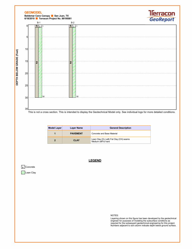
35This is not a cross section. This is intended to display the Geotechnical Model only. See individual logs for more detailed conditions.
DE
PT
H B
EL
OW
GR
AD
E (
Fee
t)6/18/2019 Terracon Project No. 88195081Baldemar Cano Canopy San Juan, TX
LEGEND
Concrete
Lean Clay
Concrete and Base Material
Lean Clay (CL) with Fat Clay (CH) seamsMedium stiff to hard
Layering shown on this figure has been developed by the geotechnicalengineer for purposes of modeling the subsurface conditions asrequired for the subsequent geotechnical engineering for this project.Numbers adjacent to soil column indicate depth below ground surface.
NOTES:
GEOMODEL
Model Layer General DescriptionLayer Name
1
2
PAVEMENT
CLAY
1
30
1
2
B-1
1
30
1
2
B-2

SUPPORTING INFORMATION
Contents:
General Notes
Unified Soil Classification System
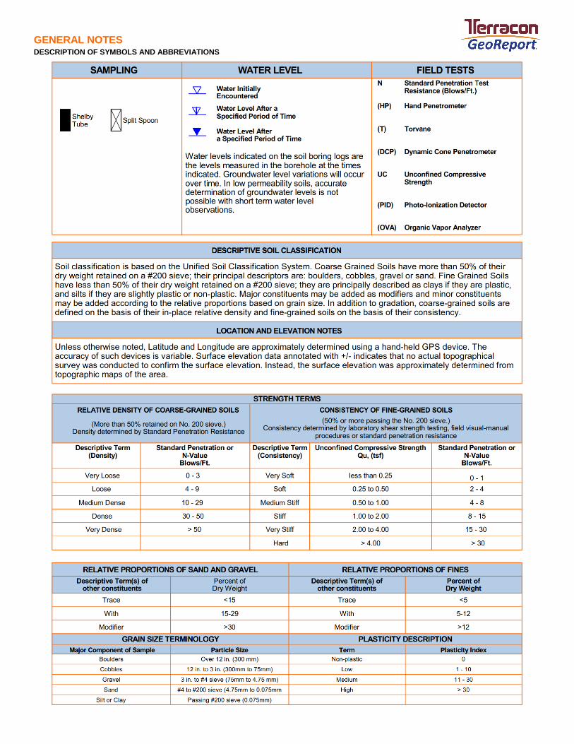
GENERAL NOTES DESCRIPTION OF SYMBOLS AND ABBREVIATIONS
GEN ER AL N OTES
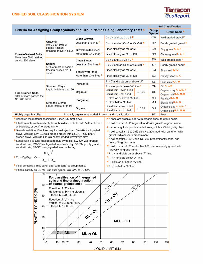
UNIFIED SOIL CLASSIFICATION SYSTEM
UNIFIED SOIL C LASSIFIC AT ION SYST EM
Criteria for Assigning Group Symbols and Group Names Using Laboratory Tests A Soil Classification
Group Symbol
Group Name B
Coarse-Grained Soils: More than 50% retained on No. 200 sieve
Gravels: More than 50% of coarse fraction retained on No. 4 sieve
Clean Gravels:
Less than 5% fines C
Cu 4 and 1 Cc 3 E GW Well-graded gravel F
Cu 4 and/or [Cc<1 or Cc>3.0] E GP Poorly graded gravel F
Gravels with Fines:
More than 12% fines C
Fines classify as ML or MH GM Silty gravel F, G, H
Fines classify as CL or CH GC Clayey gravel F, G, H
Sands: 50% or more of coarse fraction passes No. 4 sieve
Clean Sands:
Less than 5% fines D
Cu 6 and 1 Cc 3 E SW Well-graded sand I
Cu 6 and/or [Cc<1 or Cc>3.0] E SP Poorly graded sand I
Sands with Fines:
More than 12% fines D
Fines classify as ML or MH SM Silty sand G, H, I
Fines classify as CL or CH SC Clayey sand G, H, I
Fine-Grained Soils: 50% or more passes the No. 200 sieve
Silts and Clays: Liquid limit less than 50
Inorganic: PI 7 and plots on or above “A” line J
CL Lean clay K, L, M
PI 4 or plots below “A” line J ML Silt K, L, M
Organic: Liquid limit - oven dried
0.75 OL Organic clay K, L, M, N
Liquid limit - not dried Organic silt K, L, M, O
Silts and Clays: Liquid limit 50 or more
Inorganic: PI plots on or above “A” line CH Fat clay K, L, M
PI plots below “A” line MH Elastic Silt K, L, M
Organic: Liquid limit - oven dried
0.75 OH Organic clay K, L, M, P
Liquid limit - not dried Organic silt K, L, M, Q
Highly organic soils: Primarily organic matter, dark in color, and organic odor PT Peat
A Based on the material passing the 3-inch (75-mm) sieve.
B If field sample contained cobbles or boulders, or both, add “with cobbles
or boulders, or both” to group name.
C Gravels with 5 to 12% fines require dual symbols: GW-GM well-graded
gravel with silt, GW-GC well-graded gravel with clay, GP-GM poorly graded gravel with silt, GP-GC poorly graded gravel with clay.
D Sands with 5 to 12% fines require dual symbols: SW-SM well-graded
sand with silt, SW-SC well-graded sand with clay, SP-SM poorly graded sand with silt, SP-SC poorly graded sand with clay.
E Cu = D60/D10 Cc =
6010
2
30
DxD
)(D
F If soil contains 15% sand, add “with sand” to group name.
G If fines classify as CL-ML, use dual symbol GC-GM, or SC-SM.
H If fines are organic, add “with organic fines” to group name.
I If soil contains 15% gravel, add “with gravel” to group name.
J If Atterberg limits plot in shaded area, soil is a CL-ML, silty clay.
K If soil contains 15 to 29% plus No. 200, add “with sand” or “with
gravel,” whichever is predominant.
L If soil contains 30% plus No. 200 predominantly sand, add
“sandy” to group name.
M If soil contains 30% plus No. 200, predominantly gravel, add
“gravelly” to group name.
N PI 4 and plots on or above “A” line.
O PI 4 or plots below “A” line.
P PI plots on or above “A” line.
Q PI plots below “A” line.