Embed Size (px)
Citation preview
REPORT C OVER PAGE
Geotechnical Engineering Report Monopole Telecommunications Tower
Easton, Connecticut
September 29, 2017
Terracon Project No. J2175120
Prepared for:
InSite Wireless Group LLC
Boston, Massachusetts
Prepared by:
Terracon Consultants, Inc.
Rocky Hill, Connecticut
Terracon Consultants, Inc. 201 Hammer Mil l Road Rocky Hil l , Connecticut 06067
P (860) 721 1900 F (860) 721 1939 terracon.com
REPORT C OVER LETTER TO SIGN
September 29, 2017
InSite Wireless Group LLC
6519 Towpath Road
Boston, Massachusetts 13057
Attn: Robert Mitchell / Tower Operations Manager – Northeast Region
P: (617)-877-3691
Re: Geotechnical Engineering Report
Monopole Telecommunications Tower
515 Morehouse Road
Easton, Connecticut
Terracon Project No. J2175120
Dear Mr. Mitchell:
We have completed the Geotechnical Engineering services for the above referenced project. This
study was performed in general accordance with our Task Order dated September 1, 2017 issued
under the Master Services Agreement dated July 11, 2013. This report presents the findings of the
subsurface exploration and provides geotechnical recommendations concerning earthwork and the
design foundations for the proposed telecommunications tower and accompanying equipment
cabinets and generator slabs.
We appreciate the opportunity to be of service to you on this project. If you have any questions
concerning this report, or if we may be of further service, please contact us.
Sincerely,
Terracon Consultants, Inc.
Rachael C. Gaspard Brian D. Opp, P.E.
Field Geologist Geotechnical Department Manager

Responsive ■ Resourceful ■ Reliable
REPORT TOPICS
REPORT TOPICS
REPORT SUMMARY ....................................................................................................... I INTRODUCTION ............................................................................................................. 1
SITE CONDITIONS ......................................................................................................... 2 PROJECT DESCRIPTION .............................................................................................. 2 GEOTECHNICAL CHARACTERIZATION ...................................................................... 3 GEOTECHNICAL OVERVIEW ....................................................................................... 3 EARTHWORK ................................................................................................................ 4
SHALLOW FOUNDATIONS ........................................................................................... 7 GENERAL COMMENTS ............................................................................................... 10
Note: This report was originally delivered in a web-based format. Orange Bold text in the report indicates a referenced
section heading. The PDF version also includes hyperlinks which direct the reader to that section and clicking on the
logo will bring you back to this page. For more interactive features, please view your project online at
client.terracon.com.
ATTACHMENTS
EXPLORATION AND TESTING PROCEDURES
SITE LOCATION AND EXPLORATION PLAN
EXPLORATION RESULTS
SUPPORTING INFORMATION
Geotechnical Engineering Report
Monopole Telecommunications Tower ■ Easton, Connecticut
September 29, 2017 ■ Terracon Project No. J2175120
Responsive ■ Resourceful ■ Reliable i
REPORT SUMMARY
Topic 1
Overview Statement 2
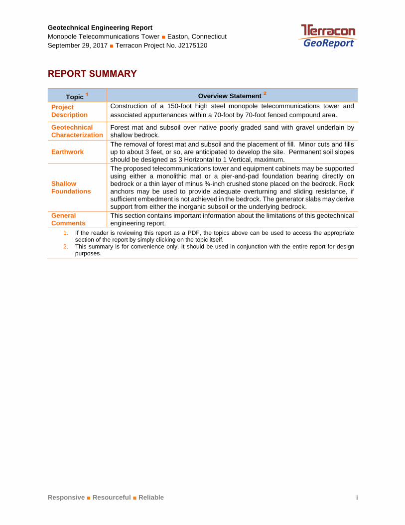
Project Description
Construction of a 150-foot high steel monopole telecommunications tower and
associated appurtenances within a 70-foot by 70-foot fenced compound area.
Geotechnical Characterization
Forest mat and subsoil over native poorly graded sand with gravel underlain by shallow bedrock.
Earthwork The removal of forest mat and subsoil and the placement of fill. Minor cuts and fills up to about 3 feet, or so, are anticipated to develop the site. Permanent soil slopes should be designed as 3 Horizontal to 1 Vertical, maximum.
Shallow Foundations
The proposed telecommunications tower and equipment cabinets may be supported using either a monolithic mat or a pier-and-pad foundation bearing directly on bedrock or a thin layer of minus ¾-inch crushed stone placed on the bedrock. Rock anchors may be used to provide adequate overturning and sliding resistance, if sufficient embedment is not achieved in the bedrock. The generator slabs may derive support from either the inorganic subsoil or the underlying bedrock.
General Comments
This section contains important information about the limitations of this geotechnical engineering report.
1. If the reader is reviewing this report as a PDF, the topics above can be used to access the appropriate section of the report by simply clicking on the topic itself.
2. This summary is for convenience only. It should be used in conjunction with the entire report for design purposes.
Responsive ■ Resourceful ■ Reliable 1
INTRODUCTION
Geotechnical Engineering Report
Monopole Telecommunications Tower
515 Morehouse Road
Easton, Connecticut Terracon Project No. J2175120
September 29, 2017
INTRODUCTION
This report presents the results of our subsurface exploration and geotechnical engineering
services performed for the proposed telecommunication tower to be located at 515 Morehouse
Road in Easton, Connecticut. The purpose of these services is to provide information and
geotechnical engineering recommendations relative to:
■ Subsurface soil conditions ■ Foundation design and construction
■ Groundwater conditions ■ Slab design and construction
■ Site preparation and earthwork ■ Seismic site classification per IBC
The geotechnical engineering scope of services for this project included the advancement of one
test boring (B-1) to a depth of approximately 13 feet below ground surface (BGS) and three test
probes (P-1, P-2, and P-2A) to depths ranging from about 1 to 5 feet BGS.
Maps showing the site and boring locations are shown in the Site Location and Exploration
Plan sections, respectively. The results of the field explorations are included on the boring logs
in the Exploration Results section of this report.
Geotechnical Engineering Report
Monopole Telecommunications Tower ■ Easton, Connecticut
September 29, 2017 ■ Terracon Project No. J2175120
Responsive ■ Resourceful ■ Reliable 2
SITE CONDITIONS
The following description of site conditions is derived from our site visit in association with the
field exploration and our review of publicly available geologic and topographic maps.
Item Description
Parcel Information
515 Morehouse Road, located southeast of Samuel Staples Elementary
School, in the city of Easton, Connecticut.
Latitude: 41° 14’ 08.10” N
Longitude: 73° 17’ 07.34” W
See Site Location
Existing Improvements Forested Land
Current Ground Cover Forest Mat and Trees
Existing Topography Steep gradient to the southeast
Geology
The Surficial Materials Map of Connecticut, 1992, identifies the native soils
in the vicinity of the site as being glacial till. The Bedrock Geologic Map of
Connecticut, 1985, indicates that the bedrock underlying the site, at depth,
consists of the Straits Schist (Goshen Formation of Massachusetts).
PROJECT DESCRIPTION
Our initial understanding of the project was provided in our proposal and was discussed in the
project planning stage. A period of collaboration has transpired since the project was initiated,
and our final understanding of the project conditions is as follows:
Item Description
Information Provided Drawing set titled “CT254 Easton”, Sheet No. SP-1, revised March 15, 2017, by All-Points Technology Corporation of Killingworth, Connecticut.
Project Description
The construction of a 150-foot high steel monopole telecommunications
tower, equipment shelter, generator and propane tank within a 70-foot
by 70-foot fenced compound area.
Estimated Maximum Loads ■ Tower dead load: 60 kips ■ Equipment pads: 150 pounds per square foot (psf).
Grading/Slopes Minor cuts and fills up to about 3 feet, or so, are anticipated to develop the site. Permanent soil slopes should be designed as 3 Horizontal to 1 Vertical (3H:1V) maximum.
Geotechnical Engineering Report
Monopole Telecommunications Tower ■ Easton, Connecticut
September 29, 2017 ■ Terracon Project No. J2175120
Responsive ■ Resourceful ■ Reliable 3
GEOTECHNICAL CHARACTERIZATION
Subsurface Profile
Subsurface conditions at the exploration locations can be generalized as follows:
Stratum Approximate Depth to
Bottom of Stratum (feet) Material Description 1 Consistency/Density
1 1 to 3.5 Poorly graded sand (SP), with
gravel, brown Medium dense
2 N/A
Mica Schist, slightly weathered,
medium strong to strong, close to
moderate joint spacing, gray
N/A
1. Forest mat (about 2 inches in thickness) was encountered at the ground surface of the explorations.
Conditions encountered at each exploration location are indicated on the individual logs shown in
the Exploration Results section and are attached to this report. Stratification boundaries on the
logs represent the approximate location of changes in native soil/rock types; in-situ, the transition
between materials may be gradual.
Groundwater Conditions
Groundwater was not observed in our explorations while drilling, or for the short duration the
explorations could remain open. However, groundwater may be perched on the relatively
impermeable bedrock. Groundwater level fluctuations occur due to seasonal variations in the
amount of rainfall, runoff and other factors not evident at the time the borings were performed.
Therefore, groundwater levels during construction or at other times in the life of the structure may
be higher or lower than the levels indicated on the boring logs. The possibility of groundwater
level fluctuations should be considered when developing the design and construction plans for
the project.
GEOTECHNICAL OVERVIEW
The proposed telecommunications tower may be supported on either a monolithic mat or a pier-
and-pad foundation bearing directly on bedrock or on a thin layer of minus ¾-inch crushed stone
placed on the bedrock. Sand and gravel fill should not be placed directly over bedrock. Rock
anchors may be used in order to provide adequate overturning and sliding resistance, if sufficient
embedment is not achieved in the bedrock. The proposed equipment platform may derive support
from either the inorganic subsoil or the underlying bedrock. Design recommendations are
presented in the following sections.
Geotechnical Engineering Report
Monopole Telecommunications Tower ■ Easton, Connecticut
September 29, 2017 ■ Terracon Project No. J2175120
Responsive ■ Resourceful ■ Reliable 4
We recommend that the exposed subgrades be thoroughly evaluated after excavation to
proposed grade. We further recommend that the geotechnical engineer be retained to evaluate
the bearing material for the foundation subgrade.
The General Comments section provides an understanding of the report limitations.
EARTHWORK
Site Preparation
Preparation of the site should include removal of topsoil, organic subsoil (subsoil with visible
roots), or otherwise unsuitable materials. The soil subgrade should be proof rolled with a vibratory
roller or heavy plate compactor. Unstable subgrades should be removed and replaced with
compacted Structural Fill or ¾-inch sized crushed stone, as necessary. If required, Structural Fill
may then be placed within the compound area to attain the required grade. Bedrock subgrades,
if encountered, should not be steeper than 4 Horizontal to 1 Vertical (4H:1V). Low spots in the
bedrock subgrade may be filled with lean concrete or ¾-inch crushed stone to provide a
reasonably level surface. Bedrock subgrades do not require proof rolling.
Reuse on Onsite Materials
Based on our visual observations of the exploration results, it is our opinion that the native poorly
graded sand with gravel may be selectively reused for Common and Structural Fill, provided it is
mixed with imported granular material (such that it is close to meeting our gradation requirements
presented below), it is placed at moisture contents suitable to facilitate compaction, and it is
compacted to the densities provided below. Cobbles and boulders should be culled from the
material prior to reuse.
Fill Material Types
Fill should meet the following material property requirements:
Fill Type 1 USCS Classification Acceptable Locations for Placement
Structural Fill 2
GW, GW-GM, SW,
SW-SM, SP, GP
All locations and elevations, including backfill of the
excavation to remove existing fill. Imported soils used as
Structural Fill should meet the gradation requirements in
Note 2 (below). Cobbles and boulders should be culled
prior to reuse.
Slab Base GW, GW-GM, SW,
SW-SM, SP, GP
Select fill beneath slabs should bee the gradation
requirements of CTDOT M.02.06, Grading B.
Geotechnical Engineering Report
Monopole Telecommunications Tower ■ Easton, Connecticut
September 29, 2017 ■ Terracon Project No. J2175120
Responsive ■ Resourceful ■ Reliable 5
Fill Type 1 USCS Classification Acceptable Locations for Placement
Common Fill 3
Varies
Common Fill may be used for general site grading.
Common Fill should not be used under settlement or frost-
sensitive structures. Cobbles and boulders should be culled
prior to reuse.
1. Compacted fill should consist of approved materials that are free of organic matter and debris. Frozen
material should not be used. Fill should not be placed on a frozen subgrade.
2. Imported Structural Fill should consist of inorganic, readily compactable, well-graded granular soils
with a maximum particle size of 6 inches and no more than 15 percent by weight passing the No.
200 sieve.
3. Common fill should have a maximum particle size of 6 inches and no more than 25 percent by weight
passing the US No. 200 sieve.
Fill Compaction Requirements
Structural Fill should meet the following compaction requirements:
Item Description
Fill Lift Thickness
■ 8 inches or less in loose thickness when hand operated equipment is used
■ 12 inches of less in loose thickness when heavy compaction is used
Compaction Requirements 1 95 percent maximum modified Proctor dry density (ASTM D1557, Method C)
Moisture Content – Granular Material Workable moisture levels
1. We recommend that fill be tested for moisture content and compaction during placement. Should
the results of the in-place density tests indicate the specified moisture or compaction limits have not
been met, the area represented by the test should be reworked and retested, as required, until the
specified moisture and compaction requirements are achieved.
Utility Trench Backfill
Trench excavations should be made with sufficient working space to permit construction including
backfill placement and compaction. As utility trenches can provide a conduit for groundwater flow,
trenches should be backfilled with material that approximately matches the permeability
characteristics of the surrounding soil. Should higher permeability fill be used in trenches,
consideration should be given to installing seepage collars and/or check dams to reduce the
likelihood of migration of water through the trenches. Fill placed as backfill for utilities located
below the slab should consist of compacted structural fill or suitable material.
Geotechnical Engineering Report
Monopole Telecommunications Tower ■ Easton, Connecticut
September 29, 2017 ■ Terracon Project No. J2175120
Responsive ■ Resourceful ■ Reliable 6
Grading and Drainage
We anticipate that permanent soil slopes will be required to develop the compound area. Soil
slopes should be designed at 3 Horizontal (H):1 Vertical (V). Steeper grades, up to 2H:1V, may
be feasible for slopes of limited height, but should be reviewed by Terracon prior to final design.
Permanent fill and cut slope surfaces should be vegetated, or covered with an erosion control
mat, to protect against erosion. Temporary sedimentation and erosion control methods should
be implemented during construction and left in place until the slope surface has been permanently
stabilized.
Adequate drainage should be provided at the site to reduce the likelihood of an increase in
moisture content of the foundation soils. Pavement should be sloped away from the compound
area to reduce the likelihood of water ponding near the structures.
Earthwork Construction Considerations
Although the exposed subgrade is anticipated to be relatively stable upon initial exposure, unstable
subgrade conditions could develop during general construction operations, particularly if the soils are
wetted and/or subjected to repetitive construction traffic. Should unstable subgrade conditions
develop, stabilization measures will need to be employed.
Construction traffic over the completed subgrade should be avoided to the extent practical. The
site should also be graded to prevent ponding of surface water on the prepared subgrades or in
excavations. If the subgrade should become frozen, wet, or disturbed, the affected material should
be removed, or should be scarified, moisture conditioned, and recompacted.
As a minimum, temporary excavations should be sloped or braced, as required by Occupational
Safety and Health Administration (OSHA) regulations, to provide stability and safe working
conditions. Temporary excavations will probably be required during grading operations. The
contractor, by his contract, is usually responsible for designing and constructing stable, temporary
excavations and should shore, slope or bench the sides of the excavations, as required, to
maintain stability of both the excavation sides and bottom. All excavations should comply with
applicable local, State, and federal safety regulations, including the current OSHA Excavation and
Trench Safety Standards.
Groundwater was not encountered at the time of our explorations. Therefore, we do not anticipate
that temporary dewatering will be required.
Terracon should be retained during the construction phase of the project to observe earthwork
and to perform necessary tests and observations during subgrade preparation; proofrolling;
Geotechnical Engineering Report
Monopole Telecommunications Tower ■ Easton, Connecticut
September 29, 2017 ■ Terracon Project No. J2175120
Responsive ■ Resourceful ■ Reliable 7
placement and compaction of controlled compacted fills; backfilling of excavations in the
completed subgrade; and just prior to construction of foundations.
SHALLOW FOUNDATIONS
Tower Foundation Design Recommendations
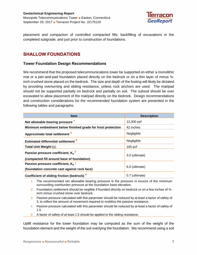
We recommend that the proposed telecommunications tower be supported on either a monolithic
mat or a pier-and-pad foundation placed directly on the bedrock or on a thin layer of minus ¾-
inch crushed stone placed on the bedrock. The size and depth of the footing will likely be dictated
by providing overturning and sliding resistance, unless rock anchors are used. The mat/pad
should not be supported partially on bedrock and partially on soil. The subsoil should be over
excavated to allow placement of the mat/pad directly on the bedrock. Design recommendations
and construction considerations for the recommended foundation system are presented in the
following tables and paragraphs.
Item Description
Net allowable bearing pressure 1
12,000 psf
Minimum embedment below finished grade for frost protection 42 inches
Approximate total settlement 2
Negligible
Estimated differential settlement 2
Negligible
Total Unit Weight (γ) 165 pcf
Passive pressure coefficient, Kp 3
(compacted fill around base of foundation) 3.0 (ultimate)
Passive pressure coefficient, Kp 4
(foundation concrete cast against rock face) 6.0 (ultimate)
Coefficient of sliding friction (bedrock) 4
0.7 (ultimate)
1. The recommended net allowable bearing pressure is the pressure in excess of the minimum surrounding overburden pressure at the foundation base elevation.
2. Foundation settlement should be neglible if founded directly on bedrock or on a few inches of ¾-inch minus crushed stone over bedrock.
3. Passive pressure calculated with this parameter should be reduced by at least a factor of safety of 3, to reflect the amount of movement required to mobilize the passive resistance.
4. Passive pressure calculated with this parameter should be reduced by at least a factor of safety of 1.5.
5. A factor of safety of at least 1.5 should be applied to the sliding resistance.
Uplift resistance for the tower foundation may be computed as the sum of the weight of the
foundation element and the weight of the soil overlying the foundation. We recommend using a soil
Geotechnical Engineering Report
Monopole Telecommunications Tower ■ Easton, Connecticut
September 29, 2017 ■ Terracon Project No. J2175120
Responsive ■ Resourceful ■ Reliable 8
unit weight of 100 pounds per cubic foot (pcf) for engineered fill overlying the footing placed as
described in this section of this report. A unit weight of 150 pcf may be used for reinforced footing
concrete. A factor of safety of 1.0 may be applied to calculations of dead load; a higher factor of
safety may be appropriate for loadings resisted by dead load.
Tower Foundation Construction Considerations
Competent bedrock was encountered in the explorations at depths ranging from about 1 to 5 feet
BGS. Therefore, excavation into bedrock will likely be required in order for the foundation to
provide adequate resistance to overturning. Bedrock excavation can be carried out by explosive
or non-explosive methods. Depending on the amount of bedrock removal, mechanical methods
may be appropriate. However, the contractor should be aware that the bedrock was competent
with a relatively fair RQD. If blasting is to be avoided, an increase in mechanical effort than is
typical for this method may be required.
Bedrock subgrades should be no steeper than 4H:1V and free of loose rock or soil. Bedrock
subgrades steeper than 4H:1V should be benched to provide a relatively level bearing surface.
Minor irregularities in the level of the rock surface may be filled with lean concrete or minus ¾-
inch crushed stone to provide a level working surface. The joints in competent bedrock should be
tight; care should be taken not to displace the joints in the bedrock during excavation.
In order for the mat/pad not to be supported partially on bedrock and partially on soil, subsoil
should be over excavated to allow placement of the mat/pad foundation on bedrock surface. The
base of foundation excavations should be free of water and loose soil/broken rock prior to placing
concrete. The geotechnical engineer should be retained to observe the foundation bearing
materials.
Groundwater was not encountered at the time of our explorations. However, the contractor should
prevent groundwater, if encountered, and surface water runoff from collecting in the excavation.
Subgrade soils that become unstable because of water and/or reworking by construction activity
should be replaced with compacted structural fill, as necessary.
Rock Anchors
In order to reduce the amount of rock excavation required, rock anchors could be installed to
provide uplift and sliding resistance. Either cement grouted or resin rock anchors could be used.
The design, installation, and proof testing of rock anchors should be completed in accordance
with the Recommendations for Prestressed Rock and Soil Anchors by the Post-Tensioning
Institute (PTI) and manufacturer’s recommendations.
Geotechnical Engineering Report
Monopole Telecommunications Tower ■ Easton, Connecticut
September 29, 2017 ■ Terracon Project No. J2175120
Responsive ■ Resourceful ■ Reliable 9
Description Value
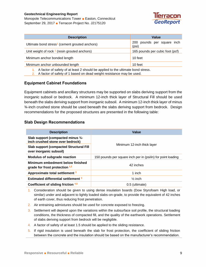
Ultimate bond stress1 (cement grouted anchors) 200 pounds per square inch (psi)
Unit weight of rock 2 (resin grouted anchors) 165 pounds per cubic foot (pcf)
Minimum anchor bonded length 10 feet
Minimum anchor unbounded length 10 feet
1. A factor of safety of at least 2 should be applied to the ultimate bond stress. 2. A factor of safety of 1 based on dead weight resistance may be used.
Equipment Cabinet Foundations
Equipment cabinets and ancillary structures may be supported on slabs deriving support from the
inorganic subsoil or bedrock. A minimum 12-inch thick layer of Structural Fill should be used
beneath the slabs deriving support from inorganic subsoil. A minimum 12-inch thick layer of minus
¾-inch crushed stone should be used beneath the slabs deriving support from bedrock. Design
recommendations for the proposed structures are presented in the following table:
Slab Design Recommendations
Description Value
Slab support (compacted minus ¾-inch crushed stone over bedrock)
Minimum 12-inch thick layer Slab support (compacted Structural Fill
over inorganic subsoil)
Modulus of subgrade reaction 150 pounds per square inch per in (psi/in) for point loading
Minimum embedment below finished
grade for frost protection 1,2 42 inches
Approximate total settlement 3 1 inch
Estimated differential settlement 3 ½ inch
Coefficient of sliding friction 4,5 0.5 (ultimate)
1. Consideration should be given to using dense insulation boards (Dow Styrofoam High load, or
similar) under and adjacent to lightly loaded slabs-on-grade, to provide the equivalent of 42 inches
of earth cover, thus reducing frost penetration.
2. Air entraining admixtures should be used for concrete exposed to freezing.
3. Settlement will depend upon the variations within the subsurface soil profile, the structural loading
conditions, the thickness of compacted fill, and the quality of the earthwork operations. Settlement
of slabs deriving support from bedrock will be negligible.
4. A factor of safety of at least 1.5 should be applied to the sliding resistance.
5. If rigid insulation is used beneath the slab for frost protection, the coefficient of sliding friction
between the concrete and the insulation should be based on the manufacturer’s recommendation.
Geotechnical Engineering Report
Monopole Telecommunications Tower ■ Easton, Connecticut
September 29, 2017 ■ Terracon Project No. J2175120
Responsive ■ Resourceful ■ Reliable 10
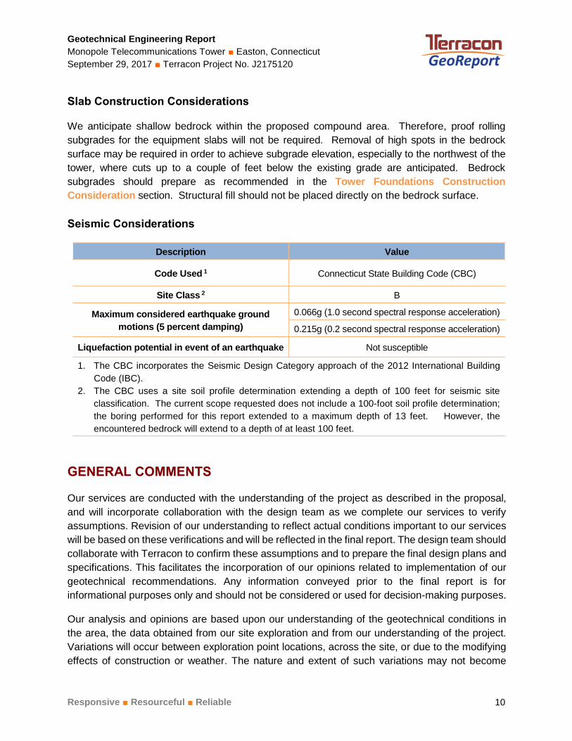
Slab Construction Considerations
We anticipate shallow bedrock within the proposed compound area. Therefore, proof rolling
subgrades for the equipment slabs will not be required. Removal of high spots in the bedrock
surface may be required in order to achieve subgrade elevation, especially to the northwest of the
tower, where cuts up to a couple of feet below the existing grade are anticipated. Bedrock
subgrades should prepare as recommended in the Tower Foundations Construction
Consideration section. Structural fill should not be placed directly on the bedrock surface.
Seismic Considerations
Description Value
Code Used 1 Connecticut State Building Code (CBC)
Site Class 2 B
Maximum considered earthquake ground
motions (5 percent damping)
0.066g (1.0 second spectral response acceleration)
0.215g (0.2 second spectral response acceleration)
Liquefaction potential in event of an earthquake Not susceptible
1. The CBC incorporates the Seismic Design Category approach of the 2012 International Building
Code (IBC).
2. The CBC uses a site soil profile determination extending a depth of 100 feet for seismic site
classification. The current scope requested does not include a 100-foot soil profile determination;
the boring performed for this report extended to a maximum depth of 13 feet. However, the
encountered bedrock will extend to a depth of at least 100 feet.
GENERAL COMMENTS
Our services are conducted with the understanding of the project as described in the proposal,
and will incorporate collaboration with the design team as we complete our services to verify
assumptions. Revision of our understanding to reflect actual conditions important to our services
will be based on these verifications and will be reflected in the final report. The design team should
collaborate with Terracon to confirm these assumptions and to prepare the final design plans and
specifications. This facilitates the incorporation of our opinions related to implementation of our
geotechnical recommendations. Any information conveyed prior to the final report is for
informational purposes only and should not be considered or used for decision-making purposes.
Our analysis and opinions are based upon our understanding of the geotechnical conditions in
the area, the data obtained from our site exploration and from our understanding of the project.
Variations will occur between exploration point locations, across the site, or due to the modifying
effects of construction or weather. The nature and extent of such variations may not become
Geotechnical Engineering Report
Monopole Telecommunications Tower ■ Easton, Connecticut
September 29, 2017 ■ Terracon Project No. J2175120
Responsive ■ Resourceful ■ Reliable 11
evident until during or after construction. Terracon should be retained as the Geotechnical
Engineer, where noted in the final report, to provide observation and testing services during
grading, excavation, foundation construction and other earth-related construction phases of the
project. If variations appear, we can provide further evaluation and supplemental
recommendations. If variations are noted in the absence of our observation and testing services
on-site, we should be immediately notified so that we can provide evaluation and supplemental
recommendations.
Our scope of services does not include either specifically or by implication any environmental or
biological (e.g., mold, fungi, bacteria) assessment of the site or identification or prevention of
pollutants, hazardous materials or conditions. If the owner is concerned about the potential for
such contamination or pollution, other studies should be undertaken.
Our services and any correspondence are intended for the sole benefit and exclusive use of our
client for specific application to the project discussed and are accomplished in accordance with
generally accepted geotechnical engineering practices with no third party beneficiaries intended.
Any third party access to services or correspondence is solely for information purposes only.
Reliance upon the services and any work product is limited to our client, and is not intended for
third parties. Any use or reliance of the provided information by third parties is done solely at their
own risk. No warranties, either express or implied, are intended or made.
Site characteristics as provided are for design purposes and not to estimate excavation cost. Any
use of our report in that regard is done at the sole risk of the excavating cost estimator as there
may be variations on the site that are not apparent in the data that could significantly impact
excavation cost. Any parties charged with estimating excavation costs should seek their own site
characterization for specific purposes to obtain the specific level of detail necessary for costing.
Site safety, and cost estimating including, excavation support, and dewatering
requirements/design are the responsibility of others. If changes in the nature, design, or location
of the project are planned, our conclusions and recommendations shall not be considered valid
unless we review the changes and either verify or modify our conclusions in writing.
ATTACHM ENTS
ATTACHMENTS
Geotechnical Engineering Report
Monopole Telecommunications Tower ■ Easton, Connecticut
September 29, 2017 ■ Terracon Project No. J2175120
Responsive ■ Resourceful ■ Reliable
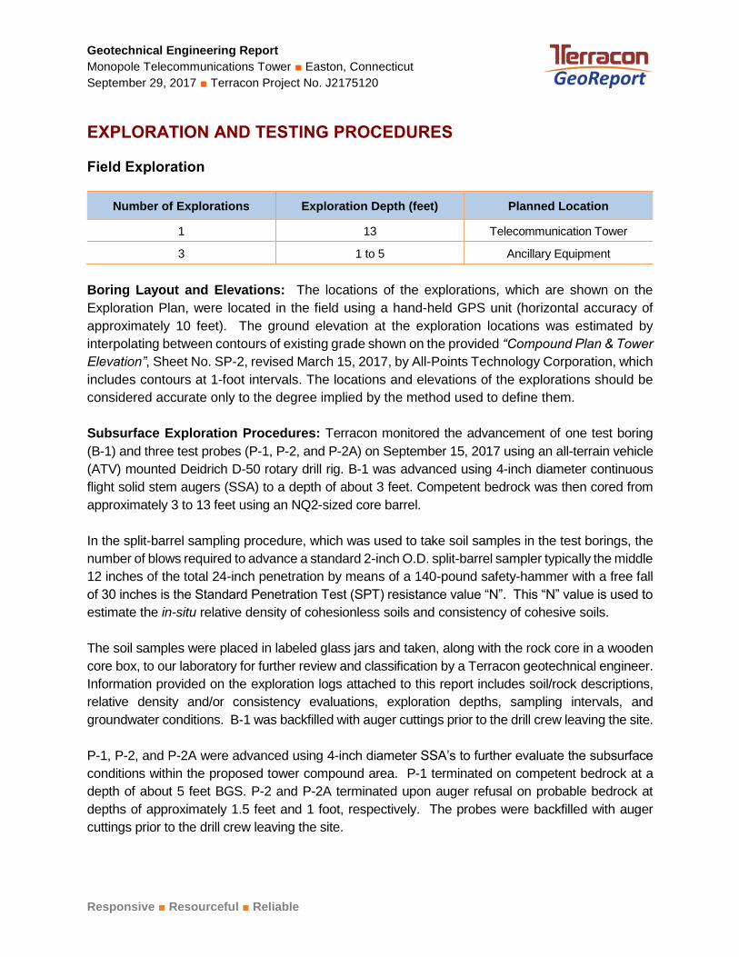
EXPLORATION AND TESTING PROCEDURES
Field Exploration
Number of Explorations Exploration Depth (feet) Planned Location
1 13 Telecommunication Tower
3 1 to 5 Ancillary Equipment
Boring Layout and Elevations: The locations of the explorations, which are shown on the
Exploration Plan, were located in the field using a hand-held GPS unit (horizontal accuracy of
approximately 10 feet). The ground elevation at the exploration locations was estimated by
interpolating between contours of existing grade shown on the provided “Compound Plan & Tower
Elevation”, Sheet No. SP-2, revised March 15, 2017, by All-Points Technology Corporation, which
includes contours at 1-foot intervals. The locations and elevations of the explorations should be
considered accurate only to the degree implied by the method used to define them.
Subsurface Exploration Procedures: Terracon monitored the advancement of one test boring
(B-1) and three test probes (P-1, P-2, and P-2A) on September 15, 2017 using an all-terrain vehicle
(ATV) mounted Deidrich D-50 rotary drill rig. B-1 was advanced using 4-inch diameter continuous
flight solid stem augers (SSA) to a depth of about 3 feet. Competent bedrock was then cored from
approximately 3 to 13 feet using an NQ2-sized core barrel.
In the split-barrel sampling procedure, which was used to take soil samples in the test borings, the
number of blows required to advance a standard 2-inch O.D. split-barrel sampler typically the middle
12 inches of the total 24-inch penetration by means of a 140-pound safety-hammer with a free fall
of 30 inches is the Standard Penetration Test (SPT) resistance value “N”. This “N” value is used to
estimate the in-situ relative density of cohesionless soils and consistency of cohesive soils.
The soil samples were placed in labeled glass jars and taken, along with the rock core in a wooden
core box, to our laboratory for further review and classification by a Terracon geotechnical engineer.
Information provided on the exploration logs attached to this report includes soil/rock descriptions,
relative density and/or consistency evaluations, exploration depths, sampling intervals, and
groundwater conditions. B-1 was backfilled with auger cuttings prior to the drill crew leaving the site.
P-1, P-2, and P-2A were advanced using 4-inch diameter SSA’s to further evaluate the subsurface
conditions within the proposed tower compound area. P-1 terminated on competent bedrock at a
depth of about 5 feet BGS. P-2 and P-2A terminated upon auger refusal on probable bedrock at
depths of approximately 1.5 feet and 1 foot, respectively. The probes were backfilled with auger
cuttings prior to the drill crew leaving the site.
Geotechnical Engineering Report
Monopole Telecommunications Tower ■ Easton, Connecticut
September 29, 2017 ■ Terracon Project No. J2175120
Responsive ■ Resourceful ■ Reliable
Field logs of the explorations were prepared by a Terracon field engineer. These logs included visual
classifications of the materials encountered during the explorations as well as interpretation by our
field engineer of the subsurface conditions between samples. Final exploration logs included with
this report represent further interpretation by the geotechnical engineer of the field logs.
Laboratory Testing
Descriptive classifications of the soils indicated on the exploration logs are in accordance with the
enclosed General Notes, the Unified Soil Classification System (USCS), and the Description of
Rock Properties. USCS symbols are also shown. A brief description of the USCS is attached to
this report. Classification was generally by visual/manual procedures.

SITE LOC ATION AND EXPLOR ATION PLAN S
SITE LOCATION AND EXPLORATION PLANS
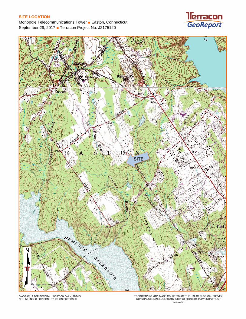
SITE LOCATION
Monopole Telecommunications Tower ■ Easton, Connecticut
September 29, 2017 ■ Terracon Project No. J2175120
TOPOGRAPHIC MAP IMAGE COURTESY OF THE U.S. GEOLOGICAL SURVEY QUADRANGLES INCLUDE: BOTSFORD, CT (1/1/1984) and WESTPORT, CT
(1/1/1975).
DIAGRAM IS FOR GENERAL LOCATION ONLY, AND IS NOT INTENDED FOR CONSTRUCTION PURPOSES
SITE
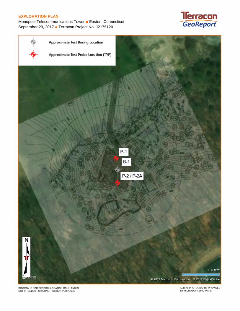
EXPLORATION PLAN
Monopole Telecommunications Tower ■ Easton, Connecticut
September 29, 2017 ■ Terracon Project No. J2175120
DIAGRAM IS FOR GENERAL LOCATION ONLY, AND IS
NOT INTENDED FOR CONSTRUCTION PURPOSES AERIAL PHOTOGRAPHY PROVIDED
BY MICROSOFT BING MAPS

EXPLOR ATION RESULTS
EXPLORATION RESULTS
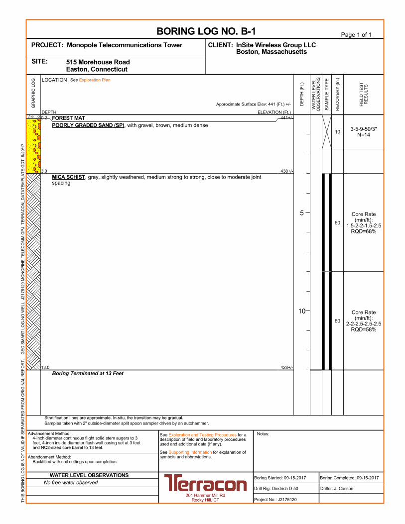
441+/-
438+/-
428+/-
3-5-9-50/3"N=14
Core Rate(min/ft):
1.5-2-2-1.5-2.5RQD=68%
Core Rate(min/ft):
2-2-2.5-2.5-2.5RQD=58%
10
60
60
0.2
3.0
13.0
FOREST MATPOORLY GRADED SAND (SP), with gravel, brown, medium dense
MICA SCHIST, gray, slightly weathered, medium strong to strong, close to moderate jointspacing
Boring Terminated at 13 Feet
GR
AP
HIC
LO
G
Stratification lines are approximate. In-situ, the transition may be gradual.Samples taken with 2" outside-diameter split spoon sampler driven by an autohammer.
TH
IS B
OR
ING
LO
G IS
NO
T V
ALI
D IF
SE
PA
RA
TE
D F
RO
M O
RIG
INA
L R
EP
OR
T.
G
EO
SM
AR
T L
OG
-NO
WE
LL J
217
5120
MO
NO
PIN
E T
ELE
CO
MM
.GP
J T
ER
RA
CO
N_D
AT
AT
EM
PLA
TE
.GD
T 9
/29/
17
ELEVATION (Ft.)
Approximate Surface Elev: 441 (Ft.) +/-
WA
TE
R L
EV
EL
OB
SE
RV
AT
ION
S
DE
PT
H (
Ft.)
5
10
SA
MP
LE T
YP
E
FIE
LD T
ES
TR
ES
ULT
S
RE
CO
VE
RY
(In
.)
DEPTH
LOCATION See Exploration Plan
Page 1 of 1
Advancement Method:4-inch diameter continuous flight solid stem augers to 3feet, 4-inch inside diameter flush wall casing set at 3 feetand NQ2-sized core barrel to 13 feet.
Abandonment Method:Backfilled with soil cuttings upon completion.
201 Hammer Mill RdRocky Hill, CT
Notes:
Project No.: J2175120
Drill Rig: Diedrich D-50
Boring Started: 09-15-2017
BORING LOG NO. B-1InSite Wireless Group LLCCLIENT:Boston, Massachusetts
Driller: J. Casson
Boring Completed: 09-15-2017
PROJECT: Monopole Telecommunications Tower
See Exploration and Testing Procedures for adescription of field and laboratory proceduresused and additional data (If any).
See Supporting Information for explanation ofsymbols and abbreviations.
515 Morehouse Road Easton, ConnecticutSITE:
No free water observedWATER LEVEL OBSERVATIONS
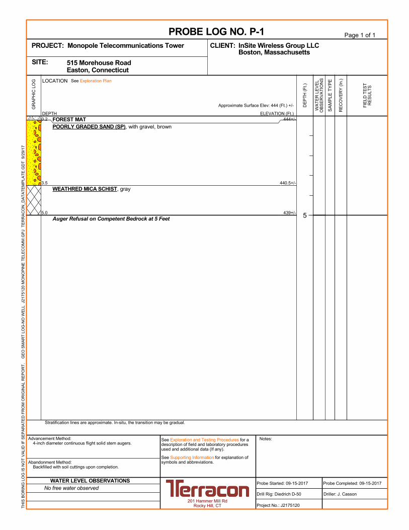
444+/-
440.5+/-
439+/-
0.2
3.5
5.0
FOREST MATPOORLY GRADED SAND (SP), with gravel, brown
WEATHRED MICA SCHIST, gray
Auger Refusal on Competent Bedrock at 5 Feet
GR
AP
HIC
LO
G
Stratification lines are approximate. In-situ, the transition may be gradual.
TH
IS B
OR
ING
LO
G IS
NO
T V
ALI
D IF
SE
PA
RA
TE
D F
RO
M O
RIG
INA
L R
EP
OR
T.
G
EO
SM
AR
T L
OG
-NO
WE
LL J
217
5120
MO
NO
PIN
E T
ELE
CO
MM
.GP
J T
ER
RA
CO
N_D
AT
AT
EM
PLA
TE
.GD
T 9
/29/
17
ELEVATION (Ft.)
Approximate Surface Elev: 444 (Ft.) +/-
WA
TE
R L
EV
EL
OB
SE
RV
AT
ION
S
DE
PT
H (
Ft.)
5
SA
MP
LE T
YP
E
FIE
LD T
ES
TR
ES
ULT
S
RE
CO
VE
RY
(In
.)
DEPTH
LOCATION See Exploration Plan
Page 1 of 1
Advancement Method:4-inch diameter continuous flight solid stem augers.
Abandonment Method:Backfilled with soil cuttings upon completion.
201 Hammer Mill RdRocky Hill, CT
Notes:
Project No.: J2175120
Drill Rig: Diedrich D-50
Probe Started: 09-15-2017
PROBE LOG NO. P-1InSite Wireless Group LLCCLIENT:Boston, Massachusetts
Driller: J. Casson
Probe Completed: 09-15-2017
PROJECT: Monopole Telecommunications Tower
See Exploration and Testing Procedures for adescription of field and laboratory proceduresused and additional data (If any).
See Supporting Information for explanation ofsymbols and abbreviations.
515 Morehouse Road Easton, ConnecticutSITE:
No free water observedWATER LEVEL OBSERVATIONS
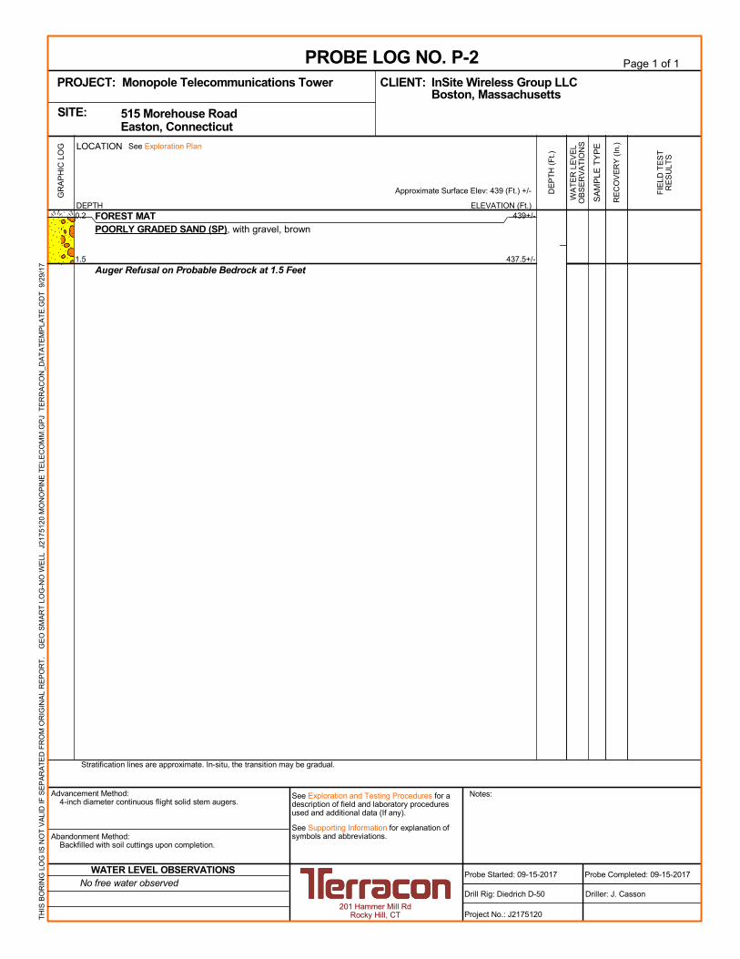
439+/-
437.5+/-
0.2
1.5
FOREST MATPOORLY GRADED SAND (SP), with gravel, brown
Auger Refusal on Probable Bedrock at 1.5 Feet
GR
AP
HIC
LO
G
Stratification lines are approximate. In-situ, the transition may be gradual.
TH
IS B
OR
ING
LO
G IS
NO
T V
ALI
D IF
SE
PA
RA
TE
D F
RO
M O
RIG
INA
L R
EP
OR
T.
G
EO
SM
AR
T L
OG
-NO
WE
LL J
217
5120
MO
NO
PIN
E T
ELE
CO
MM
.GP
J T
ER
RA
CO
N_D
AT
AT
EM
PLA
TE
.GD
T 9
/29/
17
ELEVATION (Ft.)
Approximate Surface Elev: 439 (Ft.) +/-
WA
TE
R L
EV
EL
OB
SE
RV
AT
ION
S
DE
PT
H (
Ft.)
SA
MP
LE T
YP
E
FIE
LD T
ES
TR
ES
ULT
S
RE
CO
VE
RY
(In
.)
DEPTH
LOCATION See Exploration Plan
Page 1 of 1
Advancement Method:4-inch diameter continuous flight solid stem augers.
Abandonment Method:Backfilled with soil cuttings upon completion.
201 Hammer Mill RdRocky Hill, CT
Notes:
Project No.: J2175120
Drill Rig: Diedrich D-50
Probe Started: 09-15-2017
PROBE LOG NO. P-2InSite Wireless Group LLCCLIENT:Boston, Massachusetts
Driller: J. Casson
Probe Completed: 09-15-2017
PROJECT: Monopole Telecommunications Tower
See Exploration and Testing Procedures for adescription of field and laboratory proceduresused and additional data (If any).
See Supporting Information for explanation ofsymbols and abbreviations.
515 Morehouse Road Easton, ConnecticutSITE:
No free water observedWATER LEVEL OBSERVATIONS
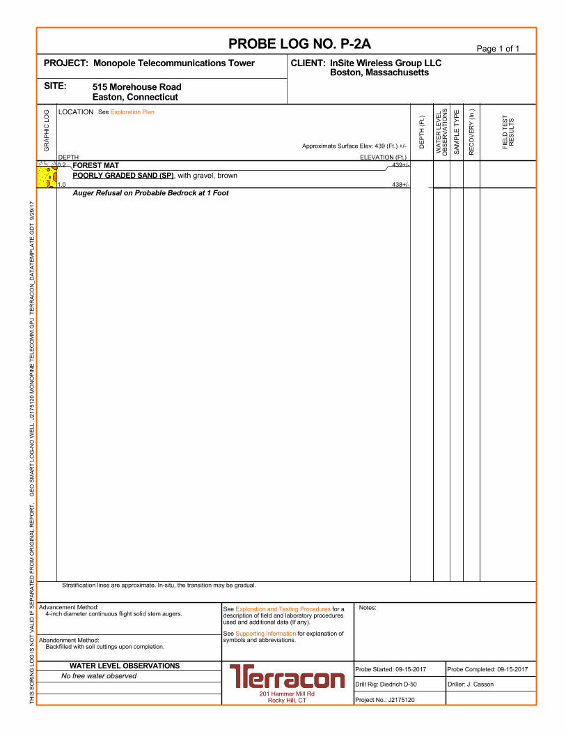
439+/-
438+/-
0.2
1.0
FOREST MATPOORLY GRADED SAND (SP), with gravel, brown
Auger Refusal on Probable Bedrock at 1 Foot
GR
AP
HIC
LO
G
Stratification lines are approximate. In-situ, the transition may be gradual.
TH
IS B
OR
ING
LO
G IS
NO
T V
ALI
D IF
SE
PA
RA
TE
D F
RO
M O
RIG
INA
L R
EP
OR
T.
G
EO
SM
AR
T L
OG
-NO
WE
LL J
217
5120
MO
NO
PIN
E T
ELE
CO
MM
.GP
J T
ER
RA
CO
N_D
AT
AT
EM
PLA
TE
.GD
T 9
/29/
17
ELEVATION (Ft.)
Approximate Surface Elev: 439 (Ft.) +/-
WA
TE
R L
EV
EL
OB
SE
RV
AT
ION
S
DE
PT
H (
Ft.)
SA
MP
LE T
YP
E
FIE
LD T
ES
TR
ES
ULT
S
RE
CO
VE
RY
(In
.)
DEPTH
LOCATION See Exploration Plan
Page 1 of 1
Advancement Method:4-inch diameter continuous flight solid stem augers.
Abandonment Method:Backfilled with soil cuttings upon completion.
201 Hammer Mill RdRocky Hill, CT
Notes:
Project No.: J2175120
Drill Rig: Diedrich D-50
Probe Started: 09-15-2017
PROBE LOG NO. P-2AInSite Wireless Group LLCCLIENT:Boston, Massachusetts
Driller: J. Casson
Probe Completed: 09-15-2017
PROJECT: Monopole Telecommunications Tower
See Exploration and Testing Procedures for adescription of field and laboratory proceduresused and additional data (If any).
See Supporting Information for explanation ofsymbols and abbreviations.
515 Morehouse Road Easton, ConnecticutSITE:
No free water observedWATER LEVEL OBSERVATIONS

SUPPORTING INFORM ATION
SUPPORTING INFORMATION
9/29/2017 J2175120
Monopole Telecommunications Tower Easton, Connecticut
0.50 to 1.00
> 4.00
Unconfined CompressiveStrengthQu, (tsf)
0.25 to 0.50
1.00 to 2.00
2.00 to 4.00
less than 0.25
Rock CoreStandardPenetrationTest
Trace
PLASTICITY DESCRIPTION
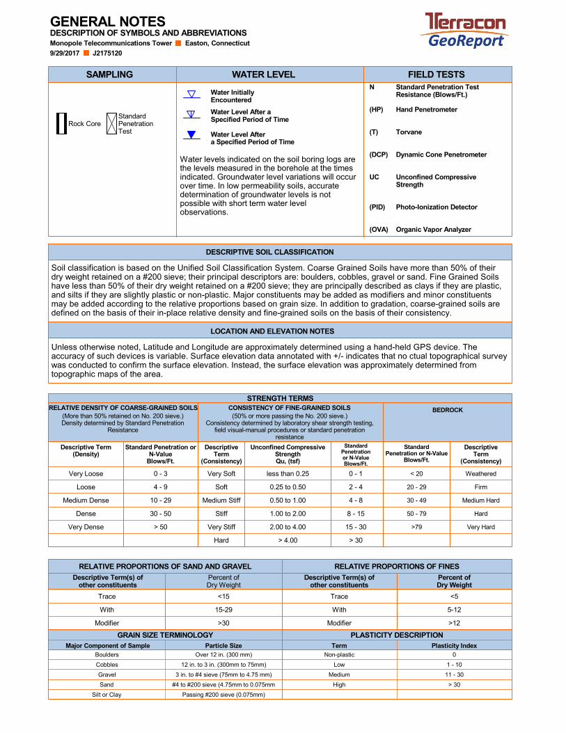
Water levels indicated on the soil boring logs arethe levels measured in the borehole at the timesindicated. Groundwater level variations will occurover time. In low permeability soils, accuratedetermination of groundwater levels is notpossible with short term water levelobservations.
DESCRIPTION OF SYMBOLS AND ABBREVIATIONSGENERAL NOTES
> 30
11 - 30
1 - 10Low
Non-plastic
Plasticity Index
#4 to #200 sieve (4.75mm to 0.075mm
Boulders
12 in. to 3 in. (300mm to 75mm)Cobbles
3 in. to #4 sieve (75mm to 4.75 mm)Gravel
Sand
Passing #200 sieve (0.075mm)Silt or Clay
Particle Size
Water Level Aftera Specified Period of Time
Water Level After aSpecified Period of Time
Water InitiallyEncountered
Soil classification is based on the Unified Soil Classification System. Coarse Grained Soils have more than 50% of theirdry weight retained on a #200 sieve; their principal descriptors are: boulders, cobbles, gravel or sand. Fine Grained Soilshave less than 50% of their dry weight retained on a #200 sieve; they are principally described as clays if they are plastic,and silts if they are slightly plastic or non-plastic. Major constituents may be added as modifiers and minor constituentsmay be added according to the relative proportions based on grain size. In addition to gradation, coarse-grained soils aredefined on the basis of their in-place relative density and fine-grained soils on the basis of their consistency.
Unless otherwise noted, Latitude and Longitude are approximately determined using a hand-held GPS device. Theaccuracy of such devices is variable. Surface elevation data annotated with +/- indicates that no ctual topographical surveywas conducted to confirm the surface elevation. Instead, the surface elevation was approximately determined fromtopographic maps of the area.
GRAIN SIZE TERMINOLOGY
RELATIVE PROPORTIONS OF FINESRELATIVE PROPORTIONS OF SAND AND GRAVEL
DESCRIPTIVE SOIL CLASSIFICATION
LOCATION AND ELEVATION NOTES
SAMPLING WATER LEVEL FIELD TESTSN
(HP)
(T)
(DCP)
UC
(PID)
(OVA)
Standard Penetration TestResistance (Blows/Ft.)
Hand Penetrometer
Torvane
Dynamic Cone Penetrometer
Unconfined CompressiveStrength
Photo-Ionization Detector
Organic Vapor Analyzer
Medium
0Over 12 in. (300 mm)
>12
5-12
<5
Percent ofDry Weight
TermMajor Component of Sample
Modifier
With
Trace
Descriptive Term(s) ofother constituents
>30Modifier
<15
Percent ofDry Weight
Descriptive Term(s) ofother constituents
With 15-29
High
Descriptive Term(Density)
Standard Penetration orN-Value
Blows/Ft.
DescriptiveTerm
(Consistency)
StandardPenetration or N-Value
Blows/Ft.
20 - 29
30 - 49
50 - 79
>79
StandardPenetrationor N-ValueBlows/Ft.
BEDROCK
STRENGTH TERMS
Very Loose
Loose
Very Soft
Dense
Weathered
Medium Hard
Firm
Very HardVery Dense
(More than 50% retained on No. 200 sieve.)Density determined by Standard Penetration
Resistance
(50% or more passing the No. 200 sieve.)Consistency determined by laboratory shear strength testing,
field visual-manual procedures or standard penetrationresistance
RELATIVE DENSITY OF COARSE-GRAINED SOILS
Soft
Medium Stiff
Stiff
Very Stiff
Hard
CONSISTENCY OF FINE-GRAINED SOILS
< 200 - 1
4 - 8
0 - 3
10 - 29
30 - 50
> 50
DescriptiveTerm
(Consistency)
Hard
2 - 4
8 - 15
15 - 30
> 30
4 - 9
Medium Dense
UNIFIED SOIL CLASSIFICATION SYSTEM
Monopole Telecommunications Tower ■ Easton, Connecticut
September 29, 2017 ■ Terracon Project No. J2175120
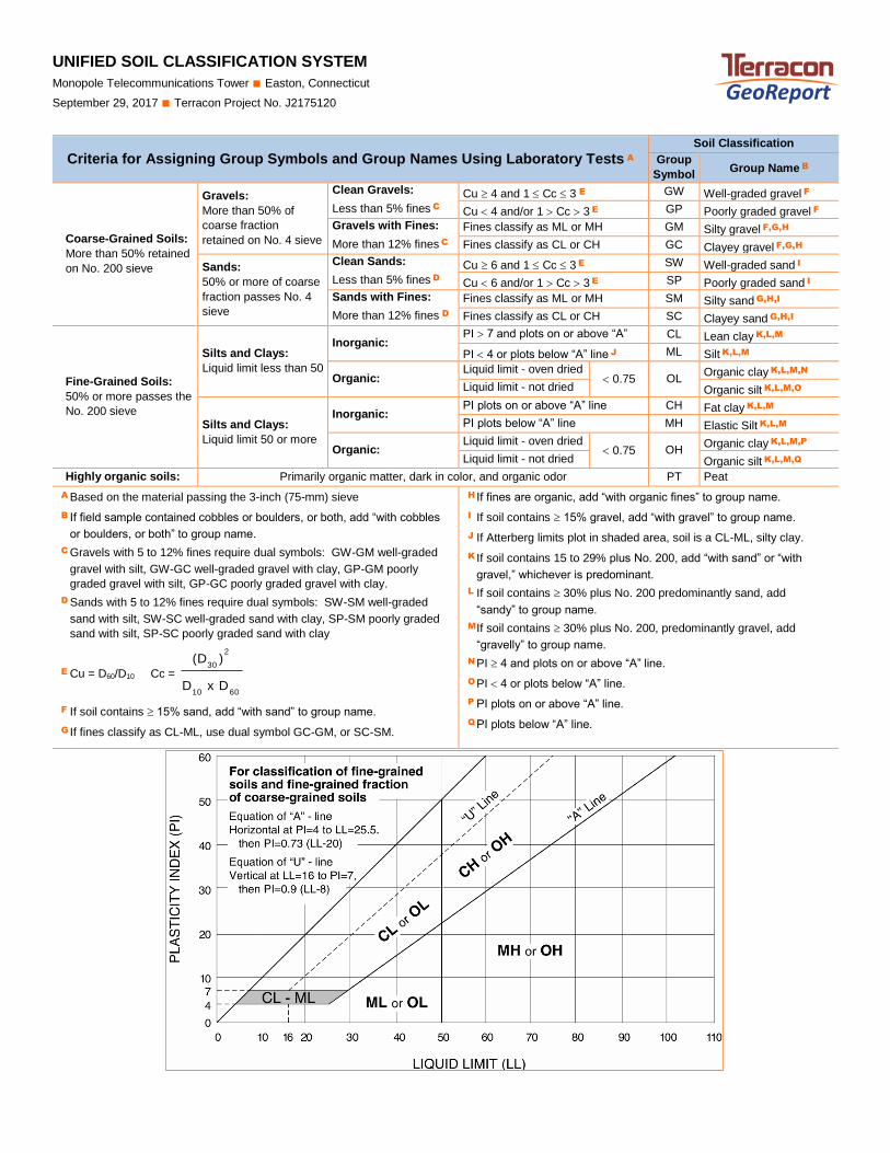
UNIFIED SOIL C LASSIFIC AT ION SYSTEM
Criteria for Assigning Group Symbols and Group Names Using Laboratory Tests A Soil Classification
Group
Symbol Group Name B
Coarse-Grained Soils:
More than 50% retained
on No. 200 sieve
Gravels:
More than 50% of
coarse fraction
retained on No. 4 sieve
Clean Gravels:
Less than 5% fines C
Cu 4 and 1 Cc 3 E GW Well-graded gravel F
Cu 4 and/or 1 Cc 3 E GP Poorly graded gravel F
Gravels with Fines:
More than 12% fines C
Fines classify as ML or MH GM Silty gravel F,G,H
Fines classify as CL or CH GC Clayey gravel F,G,H
Sands:
50% or more of coarse
fraction passes No. 4
sieve
Clean Sands:
Less than 5% fines D
Cu 6 and 1 Cc 3 E SW Well-graded sand I
Cu 6 and/or 1 Cc 3 E SP Poorly graded sand I
Sands with Fines:
More than 12% fines D
Fines classify as ML or MH SM Silty sand G,H,I
Fines classify as CL or CH SC Clayey sand G,H,I
Fine-Grained Soils:
50% or more passes the
No. 200 sieve
Silts and Clays:
Liquid limit less than 50
Inorganic: PI 7 and plots on or above “A”
line J
CL Lean clay K,L,M
PI 4 or plots below “A” line J ML Silt K,L,M
Organic: Liquid limit - oven dried
0.75 OL Organic clay K,L,M,N
Liquid limit - not dried Organic silt K,L,M,O
Silts and Clays:
Liquid limit 50 or more
Inorganic: PI plots on or above “A” line CH Fat clay K,L,M
PI plots below “A” line MH Elastic Silt K,L,M
Organic: Liquid limit - oven dried
0.75 OH Organic clay K,L,M,P
Liquid limit - not dried Organic silt K,L,M,Q
Highly organic soils: Primarily organic matter, dark in color, and organic odor PT Peat
A Based on the material passing the 3-inch (75-mm) sieve
B If field sample contained cobbles or boulders, or both, add “with cobbles
or boulders, or both” to group name.
C Gravels with 5 to 12% fines require dual symbols: GW-GM well-graded
gravel with silt, GW-GC well-graded gravel with clay, GP-GM poorly
graded gravel with silt, GP-GC poorly graded gravel with clay.
D Sands with 5 to 12% fines require dual symbols: SW-SM well-graded
sand with silt, SW-SC well-graded sand with clay, SP-SM poorly graded
sand with silt, SP-SC poorly graded sand with clay
E Cu = D60/D10 Cc =
6010
2
30
DxD
)(D
F If soil contains 15% sand, add “with sand” to group name.
G If fines classify as CL-ML, use dual symbol GC-GM, or SC-SM.
H If fines are organic, add “with organic fines” to group name.
I If soil contains 15% gravel, add “with gravel” to group name.
J If Atterberg limits plot in shaded area, soil is a CL-ML, silty clay.
K If soil contains 15 to 29% plus No. 200, add “with sand” or “with
gravel,” whichever is predominant.
L If soil contains 30% plus No. 200 predominantly sand, add
“sandy” to group name.
M If soil contains 30% plus No. 200, predominantly gravel, add
“gravelly” to group name.
N PI 4 and plots on or above “A” line.
O PI 4 or plots below “A” line.
P PI plots on or above “A” line.
Q PI plots below “A” line.
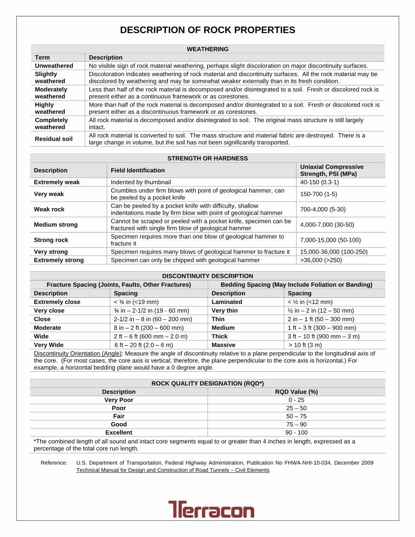
Exhibit C-3
DESCRIPTION OF ROCK PROPERTIES
WEATHERINGTerm Description Unweathered No visible sign of rock material weathering, perhaps slight discoloration on major discontinuity surfaces. Slightly weathered
Discoloration indicates weathering of rock material and discontinuity surfaces. All the rock material may be discolored by weathering and may be somewhat weaker externally than in its fresh condition.
Moderately weathered
Less than half of the rock material is decomposed and/or disintegrated to a soil. Fresh or discolored rock is present either as a continuous framework or as corestones.
Highly weathered
More than half of the rock material is decomposed and/or disintegrated to a soil. Fresh or discolored rock is present either as a discontinuous framework or as corestones.
Completely weathered
All rock material is decomposed and/or disintegrated to soil. The original mass structure is still largely intact.
Residual soil All rock material is converted to soil. The mass structure and material fabric are destroyed. There is a large change in volume, but the soil has not been significantly transported.
STRENGTH OR HARDNESS
Description Field Identification Uniaxial Compressive Strength, PSI (MPa)
Extremely weak Indented by thumbnail 40-150 (0.3-1)
Very weak Crumbles under firm blows with point of geological hammer, can be peeled by a pocket knife
150-700 (1-5)
Weak rock Can be peeled by a pocket knife with difficulty, shallow indentations made by firm blow with point of geological hammer
700-4,000 (5-30)
Medium strong Cannot be scraped or peeled with a pocket knife, specimen can be fractured with single firm blow of geological hammer
4,000-7,000 (30-50)
Strong rock Specimen requires more than one blow of geological hammer to fracture it
7,000-15,000 (50-100)
Very strong Specimen requires many blows of geological hammer to fracture it 15,000-36,000 (100-250) Extremely strong Specimen can only be chipped with geological hammer >36,000 (>250)
DISCONTINUITY DESCRIPTION
Fracture Spacing (Joints, Faults, Other Fractures) Bedding Spacing (May Include Foliation or Banding)
Description Spacing Description Spacing
Extremely close < ¾ in (<19 mm) Laminated < ½ in (<12 mm)
Very close ¾ in – 2-1/2 in (19 - 60 mm) Very thin ½ in – 2 in (12 – 50 mm)
Close 2-1/2 in – 8 in (60 – 200 mm) Thin 2 in – 1 ft (50 – 300 mm)
Moderate 8 in – 2 ft (200 – 600 mm) Medium 1 ft – 3 ft (300 – 900 mm)
Wide 2 ft – 6 ft (600 mm – 2.0 m) Thick 3 ft – 10 ft (900 mm – 3 m)
Very Wide 6 ft – 20 ft (2.0 – 6 m) Massive > 10 ft (3 m) Discontinuity Orientation (Angle): Measure the angle of discontinuity relative to a plane perpendicular to the longitudinal axis of the core. (For most cases, the core axis is vertical; therefore, the plane perpendicular to the core axis is horizontal.) For example, a horizontal bedding plane would have a 0 degree angle.
ROCK QUALITY DESIGNATION (RQD*) Description RQD Value (%) Very Poor 0 - 25
Poor 25 – 50 Fair 50 – 75
Good 75 – 90 Excellent 90 - 100
*The combined length of all sound and intact core segments equal to or greater than 4 inches in length, expressed as a percentage of the total core run length.
Reference: U.S. Department of Transportation, Federal Highway Administration, Publication No FHWA-NHI-10-034, December 2009
Technical Manual for Design and Construction of Road Tunnels – Civil Elements