Embed Size (px)
Citation preview
LVM, a division of EnGlobe Corp.
2115881 Ontario Limited
Proposed Residential Development 560-576 Conservation Drive Waterloo, Ontario
Geotechnical Engineering Report
Date: March 23, 2015 Ref. N°: 160-P-0008077-0-01-100-GE-R-0001-00
353 Bridge Street East, Kitchener (Ontario) Canada N2K 2Y5 – T 519.741.1313 | F 519.741.5422– www.lvm.ca
2115881 Ontario Limited
Proposed Residential Development 560-576 Conservation Drive
Waterloo, Ontario
Geotechnical Engineering Report |160-P-0008077-0-01-100
Prepared by:
Montana Wilson, M.Eng., P.Eng., PMP Geotechnical Group Leader
Prepared by:
Vanessa Marshall, M.Eng., P.Eng. Team Leader, Engineering Group
TABLE OF CONTENTS
160-P-0008077-0-01-100-GE-R-0001-00
PROPOSED RESIDENTIAL DEVELOPMENT – 560-576 CONSERVATION DRIVE, WATERLOO, ONTARIO
i
1 INTRODUCTION ........................................................................................................................... 1
2 PREVIOUS WORK ........................................................................................................................ 1
3 INVESTIGATION PROCEDURE .................................................................................................. 2
3.1 Field Program ...................................................................................................................... 2
3.2 Laboratory Testing .............................................................................................................. 3
4 SUMMARIZED CONDITIONS ...................................................................................................... 3
4.1 Site Description ................................................................................................................... 3
4.2 Subsoil Conditions .............................................................................................................. 4
4.2.1 Topsoil ................................................................................................................................. 4
4.2.2 Sand .................................................................................................................................... 4
4.2.3 Silt ....................................................................................................................................... 5
4.2.4 Glacial Till ............................................................................................................................ 5
4.3 Groundwater ....................................................................................................................... 6
5 DISCUSSIONS AND RECOMMENDATIONS .............................................................................. 6
5.1 General ............................................................................................................................... 6
5.2 Site Grading ........................................................................................................................ 7
5.3 Site Servicing ...................................................................................................................... 8
5.3.1 Excavations and Dewatering .............................................................................................. 8
5.3.2 Pipe Bedding ....................................................................................................................... 9
5.3.3 Trench Backfilling .............................................................................................................. 10
5.4 Pavements ........................................................................................................................ 11
5.4.1 Pavement Design .............................................................................................................. 11
5.4.2 Subdrains .......................................................................................................................... 12
5.4.3 Curbs and Sidewalks ........................................................................................................ 12
5.5 Residential Buildings ......................................................................................................... 13
5.5.1 Foundations ...................................................................................................................... 13
5.5.2 Basements ........................................................................................................................ 13
5.6 At Source Stormwater Infiltration ...................................................................................... 14
6 STATEMENT OF LIMITATIONS ................................................................................................ 16
TABLE OF CONTENTS
160-P-0008077-0-01-100-GE-R-0001-00
PROPOSED RESIDENTIAL DEVELOPMENT – 560-576 CONSERVATION DRIVE, WATERLOO, ONTARIO
ii
Tables
Table 1: Sand Particle Size Distribution Analyses .............................................................................................. 4
Table 2: Silt Particle Size Distribution Analyses Results .................................................................................... 5
Table 3: Groundwater Level Measurements ...................................................................................................... 6
Table 4: Compaction Specifications ................................................................................................................... 7
Table 5: Pavement Designs ............................................................................................................................. 11
Appendices
Appendix 1 Drawings
Appendix 2 Borehole Logs
Appendix 3 Figures
160-P-0008077-0-01-100-GE-R-0001-00
PROPOSED RESIDENTIAL DEVELOPMENT – 560-576 CONSERVATION DRIVE, WATERLOO, ONTARIO
iii
Property and Confidentiality
“This engineering document is the property of LVM, a division of EnGlobe Corp. and, as such, is protected under Copyright Law. It can only be used for the
purposes mentioned herein. Any reproduction or adaptation, whether partial or total, is strictly prohibited without having obtained LVM’s and its client’s prior
written authorization to do so.
Test results mentioned herein are only valid for the sample(s) stated in this report.
LVM’s subcontractors who may have accomplished work either on site or in laboratory are duly qualified as stated in our Quality Manual’s procurement
procedure. Should you require any further information, please contact your Project Manager.”
2115881 Ontario Limited
c/o Ian Cook Construction Limited
169 Lexington Court, Unit B-1
Waterloo, ON N2J 4R3
Attention: Ms. Nicole Simas
REVISION AND PUBLICATION REGISTER
Revision N° Date Modification And/Or Publication Details
00 2015-03-23 Report Issued
DISTRIBUTION
1 Electronic Copy / 4 Hard copies Ms. Nicole Simas, 2115881 Ontario Limited c/o Ian Cook Construction Limited
1 Electronic Copy File
alc
160-P-0008077-0-01-100-GE-R-0001-00
PROPOSED RESIDENTIAL DEVELOPMENT – 560-576 CONSERVATION DRIVE, WATERLOO, ONTARIO
1
1 INTRODUCTION
LVM, a division of EnGlobe Corp. (LVM) was retained by 2115881 Ontario Limited, c/o Ian
Cook Construction Limited, to carry out a geotechnical investigation at the site of a proposed
residential development in Waterloo, Ontario. This work was authorized by Ms. Nicole Simas
of Ian Cook Construction Limited on February 12, 2015 following submission of a detailed
proposal.
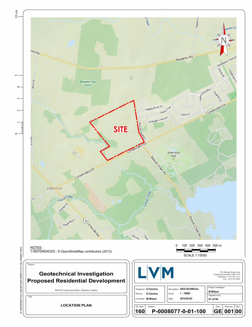
The project involves the proposed construction of a new 21.8 hectare residential development
to be situated on a parcel of land located north of Conservation Drive in Waterloo, Ontario at
the location shown on Drawing 1, in Appendix 1. It is understood the lands are designated for
residential streets and houses. The lots will be serviced with municipal water and sewer. A
preliminary site plan was unavailable at the time of this report. No details were available
regarding placement of proposed stormwater management structures.
The purpose of the investigation was to determine the subsurface soil and groundwater
conditions at the site and, based on that information, prepare this engineering report with
geotechnical recommendations pertaining to the development including site grading, site
servicing, pavement construction, house construction, excavations and dewatering, and
stormwater infiltration.
2 PREVIOUS WORK
In 2003, LVM (formerly Naylor Engineering Associates Ltd. prior to 2009) carried out a
geotechnical investigation for the land on the east side of the site. The fieldwork for this
investigation comprised of drilling of twenty-one boreholes (Boreholes 1 to 21) and excavation
of thirty-four test pits (Test Pits 1 through 34). The results of this investigation were provided in
our Geotechnical Engineering Report No. 4500G1.R01.
In 2005, LVM carried out a geotechnical investigation on Roy Schmidt Road adjacent to the
site. The fieldwork for this investigation comprised the drilling of six boreholes (Boreholes 1
through 6). The results of this investigation were provided in our Geotechnical Engineering
Report No. 4500G4.R01.
The relevant geotechnical information from the above noted reports have been incorporated
into this report.
160-P-0008077-0-01-100-GE-R-0001-00
PROPOSED RESIDENTIAL DEVELOPMENT – 560-576 CONSERVATION DRIVE, WATERLOO, ONTARIO
2
3 INVESTIGATION PROCEDURE
3.1 FIELD PROGRAM
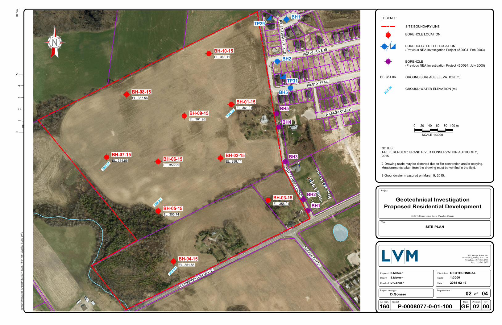
The fieldwork for this investigation was carried out between February 26 and 27, 2015 and
involved the drilling of ten boreholes (Boreholes BH-01-15 to BH-10-15) to depths of 5.0 to
8.1 m. The locations of the boreholes are shown on the Site Plan, Drawing 2 in Appendix 1.
Local utility companies were contacted prior to the start of drilling activities in order to
demarcate underground utilities near the boring locations.
The boreholes were advanced with a CME-75 track mounted drillrig equipped with continuous
flight hollow stem augers supplied and operated by a specialist drilling contractor.
In the boreholes, representative samples of the overburden were recovered at regular intervals
throughout the depths explored. Standard Penetration Tests (SPT) were carried out during
sampling operations in the boreholes using conventional split spoon equipment. The
SPT N-values recorded are plotted on the borehole logs in Appendix 2.
Samples of the cohesive soils were tested using a hand-held pocket penetrometer to
determine approximate shear strengths. The pocket penetrometer test results are plotted on
the borehole logs in Appendix 2.
Standpipes were installed in Boreholes BH-01-15, BH 04-15, BH 05-15 and BH 07-15, to allow
measurement of groundwater levels and the collection of groundwater samples. The
standpipes installation comprises 19 mm diameter pipes with slotted screens, as well as
bentonite seals near the ground surface. Details of the installations and groundwater
observations and measurements are provided on the borehole logs in Appendix 2.
The standpipes were installed in accordance with Ontario Regulation 468/10 which provides
requirements for wells in the Province of Ontario. The regulation encompasses test holes, and
provides detailed requirements for monitoring well construction, test hole sealing, well record
submission, drilling contractor licensing, well tagging, protective covers, and decommissioning.
A completed well record was submitted to the property owner and the Ministry of Environment
for Ontario as per Ontario Regulation 468/10. A licensed well technician must properly
decommission all standpipes before construction according to Regulation 903 of the Ontario
Water Resources Act.
Upon completion of drilling, the remaining boreholes were backfilled with bentonite in
accordance with the Ontario Regulation 468/10 (formerly Ontario Regulation 903) under the
province's Water Resources Act.
160-P-0008077-0-01-100-GE-R-0001-00
PROPOSED RESIDENTIAL DEVELOPMENT – 560-576 CONSERVATION DRIVE, WATERLOO, ONTARIO
3
The fieldwork was monitored throughout by a member of our geotechnical engineering staff,
who documented the drilling procedures; recorded the results of the SPT and pocket
penetrometer tests; documented the soil stratigraphies; monitored the groundwater conditions;
documented the installation of the standpipes and, cared for the recovered soil samples.
The borehole locations and ground surface elevations were surveyed by LVM using Sokkia
Model GXR 1 Global Navigation Satellite System (GNSS) rover. The borehole locations were
referenced to Universal Trans Mercator North American Datum of 1983 (UTM NAD83)
coordinates; the zone referenced (17T) has been excluded for presentation purposes. The
ground surface elevations are geodetic, based on GNSS and local base station telemetry with
a vertical root mean square error of less than 20 mm.
3.2 LABORATORY TESTING
All soil samples secured during this investigation were returned to our laboratory for visual
examination, as well as moisture content tests. The moisture content test results are plotted
on the borehole logs in Appendix 2. The geotechnical laboratory tests carried out on selected
samples of the major subsurface soils from the investigation comprised the following:
five particle size distribution analyses with results plotted on Figure 1 in Appendix 3; and,
two standard Proctor moisture-density tests with results plotted on Figures 2 and 3 in
Appendix 3.
The soil samples will be stored for a period of three months from the date of sampling. After
this time, they will be discarded unless prior arrangements have been made for longer storage.
4 SUMMARIZED CONDITIONS
4.1 SITE DESCRIPTION
The subject property is located on the north side of Conservation Drive at the northwest corner
of Waterloo, Ontario. The property is bordered on the east by an existing residential
development and Roy Schmidt Road; on the south by Conservation Drive; on the west by a
natural area and Beaver Creek; and on the north by agricultural land. There are two houses at
570 and 576 Conservation Drive.
The property currently comprises mostly agricultural land. The ground surface at the site
slopes down from east to west (Elevation 363.1 m to Elevation 354.8 m) and from north to
south (Elevation 357.6 m to Elevation 351.9 m).
160-P-0008077-0-01-100-GE-R-0001-00
PROPOSED RESIDENTIAL DEVELOPMENT – 560-576 CONSERVATION DRIVE, WATERLOO, ONTARIO
4
4.2 SUBSOIL CONDITIONS
We refer to the appended borehole logs for detailed soil descriptions and stratigraphies; results
of SPT and pocket penetrometer testing; moisture content profiles; and, groundwater
observations and measurements.
In general, the subsurface stratigraphy contacted at the site comprise topsoil, overlying sand,
silt and glacial till. Descriptions of the various soil deposits encountered are provided in the
following subsections.
4.2.1 Topsoil
Topsoil was encountered surficially at all of the boreholes and is 150 to 1070 mm thick
(average 475 mm). The topsoil comprises dark brown silt with trace sand and was frozen at
the time of the fieldwork.
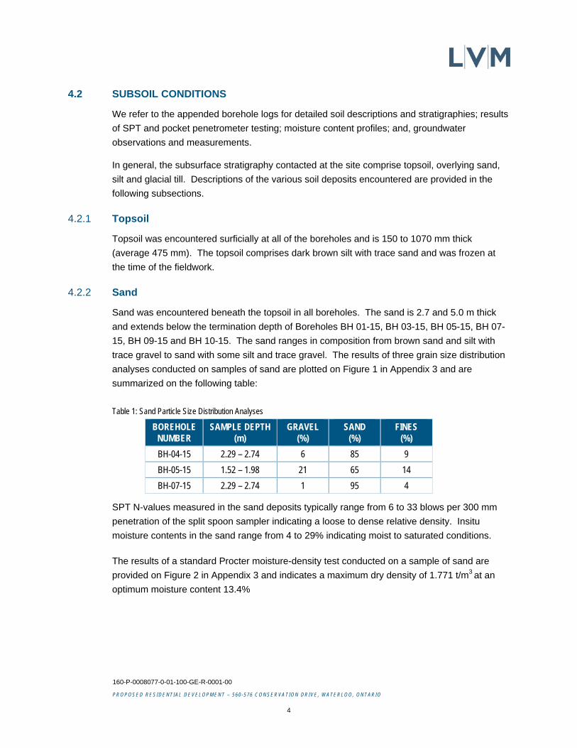
4.2.2 Sand
Sand was encountered beneath the topsoil in all boreholes. The sand is 2.7 and 5.0 m thick
and extends below the termination depth of Boreholes BH 01-15, BH 03-15, BH 05-15, BH 07-
15, BH 09-15 and BH 10-15. The sand ranges in composition from brown sand and silt with
trace gravel to sand with some silt and trace gravel. The results of three grain size distribution
analyses conducted on samples of sand are plotted on Figure 1 in Appendix 3 and are
summarized on the following table:
Table 1: Sand Particle Size Distribution Analyses
BOREHOLE NUMBER
SAMPLE DEPTH (m)
GRAVEL (%)
SAND (%)
FINES (%)
BH-04-15 2.29 – 2.74 6 85 9
BH-05-15 1.52 – 1.98 21 65 14
BH-07-15 2.29 – 2.74 1 95 4
SPT N-values measured in the sand deposits typically range from 6 to 33 blows per 300 mm
penetration of the split spoon sampler indicating a loose to dense relative density. Insitu
moisture contents in the sand range from 4 to 29% indicating moist to saturated conditions.
The results of a standard Procter moisture-density test conducted on a sample of sand are
provided on Figure 2 in Appendix 3 and indicates a maximum dry density of 1.771 t/m3 at an
optimum moisture content 13.4%
160-P-0008077-0-01-100-GE-R-0001-00
PROPOSED RESIDENTIAL DEVELOPMENT – 560-576 CONSERVATION DRIVE, WATERLOO, ONTARIO
5
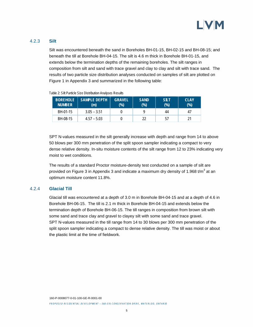
4.2.3 Silt
Silt was encountered beneath the sand in Boreholes BH-01-15, BH-02-15 and BH-08-15; and
beneath the till at Borehole BH-04-15. The silt is 4.6 m thick in Borehole BH-01-15, and
extends below the termination depths of the remaining boreholes. The silt ranges in
composition from silt and sand with trace gravel and clay to clay and silt with trace sand. The
results of two particle size distribution analyses conducted on samples of silt are plotted on
Figure 1 in Appendix 3 and summarized in the following table:
Table 2: Silt Particle Size Distribution Analyses Results
BOREHOLE NUMBER
SAMPLE DEPTH (m)
GRAVEL (%)
SAND (%)
SILT (%)
CLAY (%)
BH-01-15 3.05 – 3.51 0 9 44 47
BH-08-15 4.57 – 5.03 0 22 57 21
SPT N-values measured in the silt generally increase with depth and range from 14 to above
50 blows per 300 mm penetration of the split spoon sampler indicating a compact to very
dense relative density. In-situ moisture contents of the silt range from 12 to 23% indicating very
moist to wet conditions.
The results of a standard Proctor moisture-density test conducted on a sample of silt are
provided on Figure 3 in Appendix 3 and indicate a maximum dry density of 1.968 t/m3 at an
optimum moisture content 11.8%.
4.2.4 Glacial Till
Glacial till was encountered at a depth of 3.0 m in Borehole BH-04-15 and at a depth of 4.6 in
Borehole BH-06-15. The till is 2.1 m thick in Borehole BH-04-15 and extends below the
termination depth of Borehole BH-06-15. The till ranges in composition from brown silt with
some sand and trace clay and gravel to clayey silt with some sand and trace gravel.
SPT N-values measured in the till range from 14 to 30 blows per 300 mm penetration of the
split spoon sampler indicating a compact to dense relative density. The till was moist or about
the plastic limit at the time of fieldwork.
160-P-0008077-0-01-100-GE-R-0001-00
PROPOSED RESIDENTIAL DEVELOPMENT – 560-576 CONSERVATION DRIVE, WATERLOO, ONTARIO
6
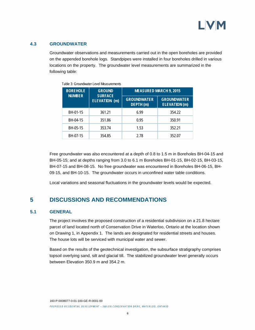
4.3 GROUNDWATER
Groundwater observations and measurements carried out in the open boreholes are provided
on the appended borehole logs. Standpipes were installed in four boreholes drilled in various
locations on the property. The groundwater level measurements are summarized in the
following table:
Table 3: Groundwater Level Measurements
BOREHOLE NUMBER
GROUND SURFACE
ELEVATION (m)
MEASURED MARCH 9, 2015
GROUNDWATER DEPTH (m)
GROUNDWATER ELEVATION (m)
BH-01-15 361.21 6.99 354.22
BH-04-15 351.86 0.95 350.91
BH-05-15 353.74 1.53 352.21
BH-07-15 354.85 2.78 352.07
Free groundwater was also encountered at a depth of 0.8 to 1.5 m in Boreholes BH-04-15 and
BH-05-15; and at depths ranging from 3.0 to 6.1 m Boreholes BH-01-15, BH-02-15, BH-03-15,
BH-07-15 and BH-08-15. No free groundwater was encountered in Boreholes BH-06-15, BH-
09-15, and BH-10-15. The groundwater occurs in unconfined water table conditions.
Local variations and seasonal fluctuations in the groundwater levels would be expected.
5 DISCUSSIONS AND RECOMMENDATIONS
5.1 GENERAL
The project involves the proposed construction of a residential subdivision on a 21.8 hectare
parcel of land located north of Conservation Drive in Waterloo, Ontario at the location shown
on Drawing 1, in Appendix 1. The lands are designated for residential streets and houses.
The house lots will be serviced with municipal water and sewer.
Based on the results of the geotechnical investigation, the subsurface stratigraphy comprises
topsoil overlying sand, silt and glacial till. The stabilized groundwater level generally occurs
between Elevation 350.9 m and 354.2 m.
160-P-0008077-0-01-100-GE-R-0001-00
PROPOSED RESIDENTIAL DEVELOPMENT – 560-576 CONSERVATION DRIVE, WATERLOO, ONTARIO
7
Based on the results of this geotechnical investigation, there are shallow groundwater levels at
the south and east portions of the property; however, the site is suitable for the proposed
residential development. The following subsections of this report contain geotechnical
recommendations pertaining to development of the property including site grading, site
servicing, pavements, residential buildings, and stormwater infiltration.
5.2 SITE GRADING
Area grading of the property will likely be required to prepare the land for the construction of
the proposed residential subdivision. A proposed grading plan was unavailable at the time this
report was issued.
Prior to carrying out any cutting and engineered fill placement, the surficial topsoil and loose
native deposits should be removed from cuts and critical fill areas. In calculating the
approximate quantity of soil to be removed, we recommend that the thicknesses on the
individual borehole logs be increased by 50 mm to account for variations and some stripping of
the mineral soil below. The topsoil material could be used for landscaping fill to raise grades in
the rear yards of the house lots or in park areas. The topsoil ranges in thickness from 0.2 to
1.1 m at the borehole locations (average 475 mm).
The existing houses located off Conservation Drive will likely be demolished. The floor slabs,
foundations, and foundation wall backfill should be removed prior to grading of this area.
Within the low-lying areas of the site where the groundwater table is quite close to the existing
ground surface (west side of site) it will likely be necessary to remove the organic deposits with
a tracked hydraulic excavator.
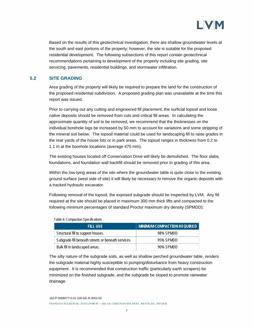
Following removal of the topsoil, the exposed subgrade should be inspected by LVM. Any fill
required at the site should be placed in maximum 300 mm thick lifts and compacted to the
following minimum percentages of standard Proctor maximum dry density (SPMDD):
Table 4: Compaction Specifications
FILL USE MINIMUM COMPACTION REQUIRED
Structural fill to support houses. 98% SPMDD
Subgrade fill beneath streets or beneath services. 95% SPMDD
Bulk fill in landscaped areas. 90% SPMDD
The silty nature of the subgrade soils, as well as shallow perched groundwater table, renders
the subgrade material highly susceptible to pumping/disturbance from heavy construction
equipment. It is recommended that construction traffic (particularly earth scrapers) be
minimized on the finished subgrade, and the subgrade be sloped to promote rainwater
drainage.
160-P-0008077-0-01-100-GE-R-0001-00
PROPOSED RESIDENTIAL DEVELOPMENT – 560-576 CONSERVATION DRIVE, WATERLOO, ONTARIO
8
The major soils likely to be generated from cut areas at the site are silt and sand. Based on
the results of insitu moisture content and standard Proctor moisture-density tests, the majority
of the on-site excavated soils from above the groundwater table will be suited for reuse as road
subgrade fill and structural fill if the grading work is carried out during relatively dry weather.
The silt is generally very moist and will require drying or blending with dry sand prior to use as
structural fill. If time is not available for drying, then this material should be used as pavement
subgrade fill and in landscaped area.
Also, if structural fill operations are carried out in the fall, winter or spring, imported granular
material is recommended. If imported fill is required onsite, we recommend structural fill used
below buildings consisting of clean granular material such as OPSS Granular ‘B’. Any imported
fill material should be tested and approved by a geotechnical engineer prior to use.
Where structural fill is placed on a wet subgrade, we suggest that only a coarse sand and
gravel material be used for the bottom few lifts. Also, the initial lift may be up to 750 mm thick
in order to ensure trafficability and minimize compaction problems associated with instability of
the subgrade caused by vibratory equipment.
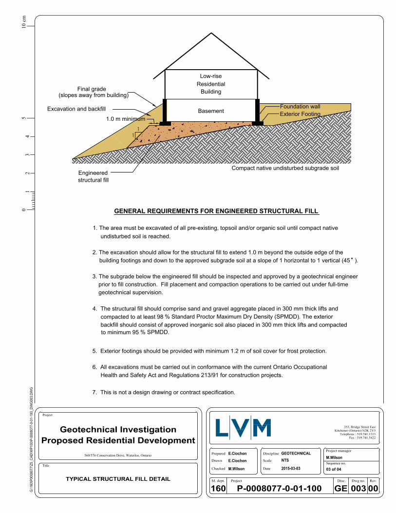
The structural fill pads should extend at least 1.0 m beyond the footing edge of any building
and down to the subgrade level at a slope of 45° to the horizontal. A typical detail for structural
fill placement beneath house foundations is shown on Drawing 3, in Appendix 1.
Full-time testing by experienced geotechnical personnel should be carried out during fill
placement and compaction to examine and approve potential sources of fill material, and to
carefully monitor the placement and verify the compaction by in-situ density testing (ASTM
D2167 or ASTM 2922).
5.3 SITE SERVICING
5.3.1 Excavations and Dewatering
Following site grading operations, the subdivision will be serviced to provide the individual lots
with water and sewer services. It is anticipated that the invert levels for the watermain and
sewers will be at conventional depths, some 2 to 4 m below finished grade through most of the
site. We recommend that LVM be allowed to check the final site grading and servicing plans for
the subdivision to ensure that the exploratory boreholes extend below the design invert
elevations. It is noted additional boreholes may be required.
160-P-0008077-0-01-100-GE-R-0001-00
PROPOSED RESIDENTIAL DEVELOPMENT – 560-576 CONSERVATION DRIVE, WATERLOO, ONTARIO
9
Temporary excavations to conventional depths for installation of underground pipes at this site
must comply with the Ontario Occupational Health and Safety Act and Regulations for
Construction Projects. The predominant soils encountered in the boreholes would be classified
as Type 3 soils (O. Reg. 213/91, s. 226(4)). Temporary side slopes must be cut at an
inclination of 1.0 horizontal to 1.0 vertical or less above the base of excavation as per O. Reg.
213/91, s. 234(2) (exclusive of groundwater effects).
Significant seepage was noted at a depth of 0.8 to 1.5 m at Boreholes BH-04-15 and BH-05-
15. A positive dewatering system installed by a specialist dewatering contractor may be
required if excavations extend below Elevation 354 m in the east portion of the site and below
Elevation 352 m in the west portion of the site. It will be necessary to flatten the excavation
side slopes where groundwater seepage is occurring to ensure stability. Every excavation that
a worker may be required to enter shall be kept reasonably free of water (O. Reg. 213/91, s.
230).
A Permit to Take Water (PTTW) is required by the Ministry of Environment in the event that the
daily taking of groundwater exceeds 50,000 L per day. If the contractor carefully plans and
stages his work so that only short sections of trench are open at a given time, it may be
possible to complete this project without the need for a PTTW.
The contractor should evaluate this latter recommendation to ensure that he is in agreement,
and he should notify the prime consultant in the event that he feels that a PTTW will be needed
on the basis of his excavation and pipe laying schedule.
The design of the dewatering system should be left to the contractor's discretion, and the
system should meet a performance specification to maintain and control the groundwater at
least 0.30 m below the invert level in order to provide a stable excavation base. Successful
dewatering operations will depend on the contractor's own experience, construction
techniques, sequencing, and efficiency of work force and plant. Also the dewatering must be in
compliance with the Ontario Water Resources Act (OWRA) and the Water Taking and Transfer
Regulation (O.Reg. 451/07).
It is recommended that several test pits be dug during the tendering stage of the project in
order that prospective contractors may familiarize themselves with the soil and groundwater
conditions to be contacted.
5.3.2 Pipe Bedding
The subgrade soils beneath the watermain and sewers will comprise native mineral soils or
compacted fill placed during the site grading operations. No support problems are anticipated
for flexible or rigid pipes founded in the native deposits or compacted on-site soils.
160-P-0008077-0-01-100-GE-R-0001-00
PROPOSED RESIDENTIAL DEVELOPMENT – 560-576 CONSERVATION DRIVE, WATERLOO, ONTARIO
10
Pipe bedding for water and sewer services should be conventional Class 'B' pipe bedding
comprising a minimum 150 mm thick layer of OPSS Granular 'A' aggregate below the pipe
invert. The bedding course may be thickened if portions of the subgrade become unduly wet
during excavation. Granular 'A' type aggregate should be provided around the pipe to at least
300 mm above the pipe. The bedding aggregate should be compacted to a minimum
95% standard Proctor maximum dry density (SPMDD). Water and sewer lines installed
outside of heated areas should be provided with a minimum 1.2 m of soil cover or equivalent
insulation for frost protection.
A well-graded clear stone such as Coarse Aggregate for HL4 Asphaltic Concrete (OPSS 1003)
could be used in the sewer trenches as bedding below the spring line of the pipe to facilitate
sump pump dewatering, if necessary. The clear stone should be compacted with a plate
tamper.
The proposed sewers could create hydraulic connections between groundwater regimes that
are not presently connected. To stop the movement of groundwater along the pipe bedding, it
is recommended that concrete or clay collars be installed around the pipe. The collars should
be at least 1.0 m long and in place of the standard bedding material. Clay seals shall be
compacted to 95% standard Proctor maximum dry density (SPMDD) as per OPSS 410.07.18.
(Also OPSD 802.095 and OPSS 1205).
Thrust blocks for the watermain should be designed using current OPSS Standards and shall
conform to OPSD 1103.010 and 1103.020. The following soil parameters may be used for
thrust restraint design:
Angle of internal friction () = 30°
Soil cohesion (c) = 0 kPa
Soil unit weight () = 20 kN/m3
The interface friction coefficient for granular bedding and smooth ductile iron pipe or PVC pipe
would be 0.60. An appropriate factor of safety should be employed.
5.3.3 Trench Backfilling
The trenches above the specified pipe bedding should be backfilled with inorganic on-site soils
placed in 300 mm thick lifts and compacted to at least 95% SPMDD.
Based on the results of insitu moisture content and standard Proctor moisture-density tests
carried out on the native overburden deposits, the majority of the on-site excavated materials
will be compactable to the required density. If imported fill is required we recommend OPSS
Granular ‘B’ be used.
If necessary, compensation for wet trench backfill conditions can be made with additional
Granular 'B' in the pavement structure.
160-P-0008077-0-01-100-GE-R-0001-00
PROPOSED RESIDENTIAL DEVELOPMENT – 560-576 CONSERVATION DRIVE, WATERLOO, ONTARIO
11
To minimize potential problems, backfilling operations should follow closely after excavation so
that only a minimal length of trench is exposed. Care should be taken to protect side slopes of
excavations by diverting surface run-off away from the excavations.
If construction extends into the winter, then the backfilling operations should be planned so that
exposure of the backfill material to frost is kept to a minimum and to ensure that frozen material
is not used as backfill.
Frequent compaction testing by experienced geotechnical personnel should be carried out to
examine and approve backfill materials, and to verify that the specified degree of compaction
has been achieved.
5.4 PAVEMENTS
5.4.1 Pavement Design
Following site grading and servicing operations, the pavement subgrade will comprise native
and recompacted sand and silt soils or imported granular fill.
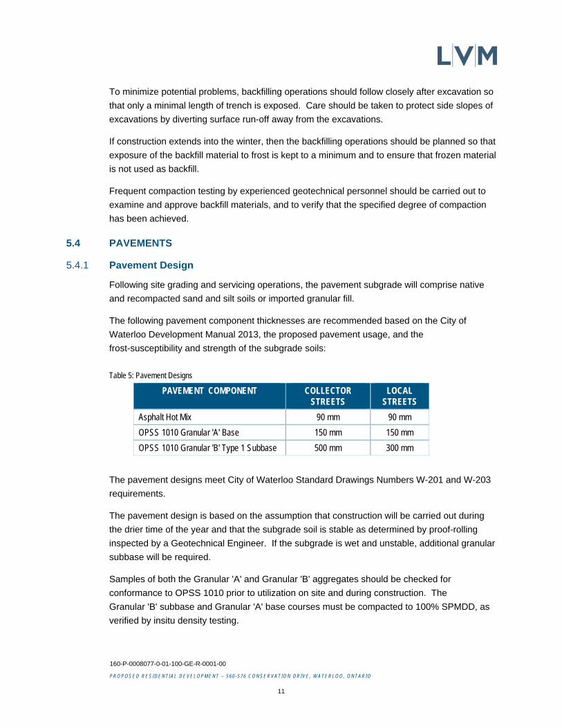
The following pavement component thicknesses are recommended based on the City of
Waterloo Development Manual 2013, the proposed pavement usage, and the
frost-susceptibility and strength of the subgrade soils:
Table 5: Pavement Designs
PAVEMENT COMPONENT COLLECTOR STREETS
LOCAL STREETS
Asphalt Hot Mix 90 mm 90 mm
OPSS 1010 Granular 'A' Base 150 mm 150 mm
OPSS 1010 Granular 'B' Type 1 Subbase 500 mm 300 mm
The pavement designs meet City of Waterloo Standard Drawings Numbers W-201 and W-203
requirements.
The pavement design is based on the assumption that construction will be carried out during
the drier time of the year and that the subgrade soil is stable as determined by proof-rolling
inspected by a Geotechnical Engineer. If the subgrade is wet and unstable, additional granular
subbase will be required.
Samples of both the Granular 'A' and Granular 'B' aggregates should be checked for
conformance to OPSS 1010 prior to utilization on site and during construction. The
Granular 'B' subbase and Granular 'A' base courses must be compacted to 100% SPMDD, as
verified by insitu density testing.
160-P-0008077-0-01-100-GE-R-0001-00
PROPOSED RESIDENTIAL DEVELOPMENT – 560-576 CONSERVATION DRIVE, WATERLOO, ONTARIO
12
The asphaltic concrete should comprise a binder layer of HL8 and a surface layer of HL3. It is
recommended that the compacted thicknesses be 50 mm of HL8 binder and 40 mm of HL3
surface for both collector and local streets.
The asphaltic concrete paving materials should conform to the requirements of OPSS 1150.
The asphalt should be placed and compacted in accordance with OPSS 310. The
Performance Graded Asphalt Cement designation for the asphaltic concrete is 58-28.
The need for continuous paving supervision by a qualified pavement technician, and quality
control testing during pavement construction cannot be over emphasized.
All materials and construction services required for the work should be in accordance with the
applicable sections of the Ontario Provincial Standard Specifications.
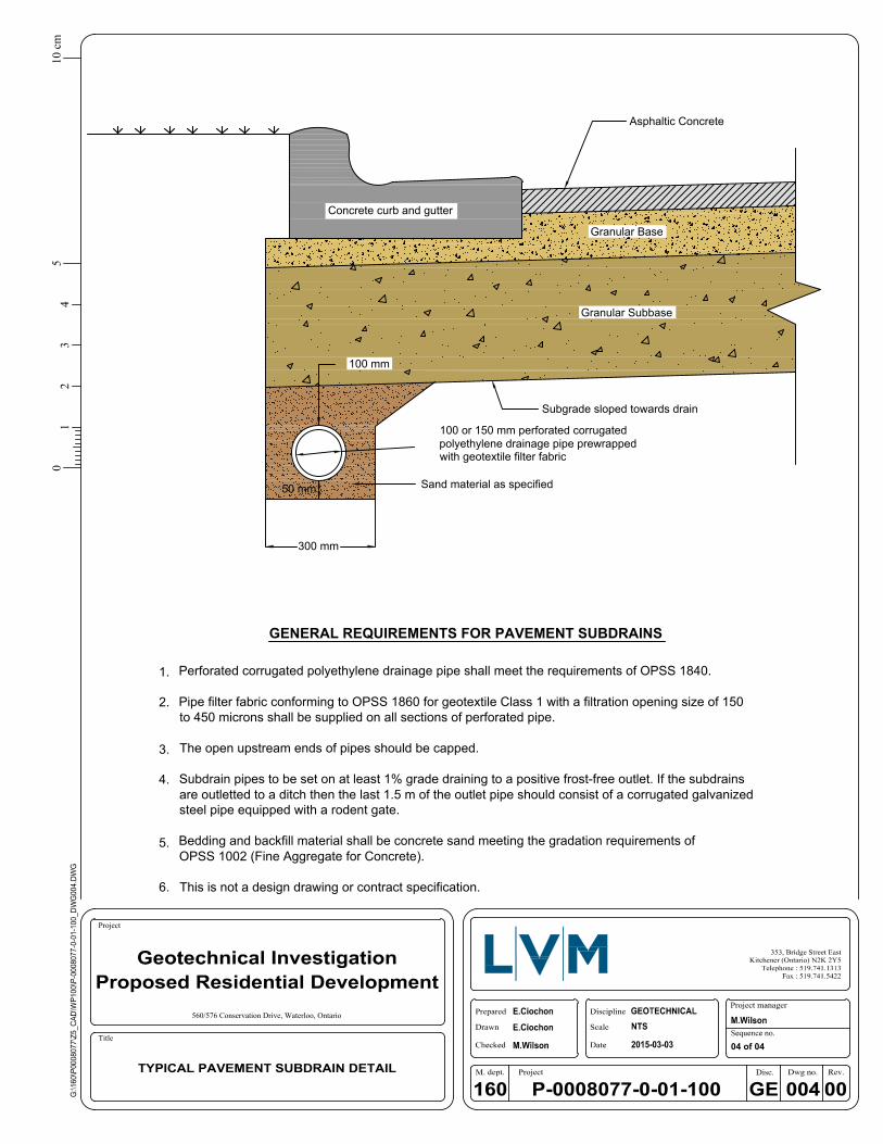
5.4.2 Subdrains
Portions of he native subgrade soils have poor natural drainage therefore we recommend that
where silt is encountered at the subgrade, subdrains be installed continuously along both sides
of the street and connected to the catch basins. Where sand deposits are encountered at the
subgrade level it is recommended that subdrain stubs be installed at the catchbasins. This
should be confirmed by a geotechnical engineer at the time of subgrade preparation.
The purpose of the subdrains is to remove excess subsurface water in order to improve
pavement serviceability and increase the pavement life. A detail for a typical pavement
subdrain is provided on Drawing 4, in Appendix 1.
The work of subdrain installation shall be in accordance with OPSS 405 and OPSD 216.021.
The subdrain shall be 100 or 150 mm diameter perforated pipe conforming to OPSS 1801 or
1840, and wrapped with geotextile conforming to OPSS 1860.
5.4.3 Curbs and Sidewalks
The concrete for curb and gutter should be proportioned, mixed, placed, and cured in
accordance with the requirements of OPSS 353 and OPSS.MUNI 1350, and shall meet the
following specific requirements (OPSS 353.05.01):
minimum 28-day compressive strength = 30 MPa
coarse aggregate = 19.0 mm nominal max. size
maximum slump = 60 mm
air entrainment = 7.0 ± 1.5%
During cold weather (when the air temperature is at or is likely to fall below 5°C within
96 hours of concrete placement) the freshly placed concrete must be covered with insulating
blankets to protect against freezing, as per OPSS 904. Ice and snow must be removed from
160-P-0008077-0-01-100-GE-R-0001-00
PROPOSED RESIDENTIAL DEVELOPMENT – 560-576 CONSERVATION DRIVE, WATERLOO, ONTARIO
13
the area where concrete is to be placed and the concrete must not be placed against frozen
ground. All cold weather protection material shall be on site prior to each concrete placement.
The subgrade for the concrete sidewalks should comprise undisturbed native mineral soil or
well-compacted fill. A minimum 150 mm thick layer of compacted Granular 'A' type aggregate
should be placed beneath the sidewalk slabs. The subgrade and granular base should be
prepared in accordance with the requirements of OPSS 315.
5.5 RESIDENTIAL BUILDINGS
5.5.1 Foundations
In general, the undisturbed native mineral soils are considered suitable to support residential
house foundations. Where the footing levels will be above the existing native mineral soil
grade, structural fill will probably be used. House footings constructed on the compact native
mineral soil or approved structural fill may be designed using the minimum footing sizes
provided in the Ontario Building Code.
All founding surfaces for residential dwellings on structural fill or native soils should be
inspected by LVM personnel prior to placing concrete. The purpose of the inspection is to
ensure that the founding conditions are consistent with the design bearing intended by the
geotechnical engineer. The on-site review of the condition of the foundation soil as
foundations are constructed is an integral part of the geotechnical design function and cannot
be over emphasized. These reviews are required by Section 4.2.2.2 of the Ontario Building
Code.
Further geotechnical investigation will be necessary for large structures such as schools,
plazas or apartment buildings to provide specific recommendations for design of these
structures. The preliminary Site Classification for Seismic Site Response is 'D'.
The subgrade soils are considered to be frost susceptible and must be protected from freezing
at all times including during construction. The exterior footings or footings in unheated areas
should be provided with a minimum 1.20 m of earth cover upon final grading for frost
protection.
5.5.2 Basements
It is recommended basement floor slabs be installed above the groundwater levels and LVM
review grading plans once complete.
House basements at this site must be provided with perimeter weeping tile systems as per the
Ontario Building Code (Section 9.14). The drain tile or pipe should be laid on undisturbed or
well-compacted soil so that the top of the tile or pipe (minimum 100 mm diameter) is below the
bottom of the basement floor slab.
160-P-0008077-0-01-100-GE-R-0001-00
PROPOSED RESIDENTIAL DEVELOPMENT – 560-576 CONSERVATION DRIVE, WATERLOO, ONTARIO
14
The top and sides of the drain tile or pipe shall be surrounded with not less than 150 mm of
crushed stone or other clean coarse granular material containing no more than 10% of material
that will pass the 4 mm sieve. The pipe bedding should be wrapped with geotextile filter fabric.
The weeping tile must drain to a suitable frost-free outlet or sump.
The portion of the exterior basement wall below finished ground level must be damp-proofed
as per Section 9.13.2 of the Ontario Building Code (2012). The basement wall backfill should
be graded to prevent drainage towards the foundation after settling as per OBC 9.12.3.
The basement walls should be designed to resist the lateral earth pressure. For calculating the
lateral earth pressure, the coefficient of earth pressure (K) may be assumed as 0.5 for
cohesionless sand soils and 1.0 for silt and clay. The bulk unit weight of the retained backfill
may be taken as 21 kN/m3 for well-compacted soil. An appropriate factor of safety should be
employed.
The subgrade for the basement floor slabs should comprise undisturbed native soil or
well-compacted fill. A minimum 100 mm thick layer of coarse clean granular material
containing not more than 10% material that will pass a 4 mm sieve shall be placed beneath
slabs in houses as per Section 9.16.2 of the Ontario Building Code. If the subgrade soil is wet,
we recommend that LVM be notified and subfloor weeping tiles be placed and connected to the
sump pit.
To prevent the migration of moisture vapour into the houses from beneath basement floor
slabs, particularly where moisture sensitive floor coverings are placed, a vapour retarder shall
be placed directly beneath the floor slab that meets the requirements of the designer and
flooring manufacturer. Prior to installing moisture sensitive floor coverings, the moisture
content of the concrete slab must be determined at operational conditions by internal relative
humidity testing to ensure an acceptable slab moisture level. It should be noted that it typically
takes more than ninety days at operational conditions to lower the slabs internal relative
humidity to 85%. Different flooring systems have different responses to slab moisture (i.e.
some systems can tolerate more moisture than others), and the flooring contractor must
assess the floor moisture levels with respect to their flooring components.
5.6 AT SOURCE STORMWATER INFILTRATION
At source infiltration of water from house roof leaders into dry wells may be feasible in areas
where the natural groundwater level is below the bottom of the dry well and the native soils are
relatively free-draining.
160-P-0008077-0-01-100-GE-R-0001-00
PROPOSED RESIDENTIAL DEVELOPMENT – 560-576 CONSERVATION DRIVE, WATERLOO, ONTARIO
15
Based on the results of this investigation, the general soil profile existing at the site comprises
surficial topsoil overlying major native deposits of sand with interbeds of silt. The hydraulic
conductivity of the sand is in the order of 10-3 to 10-5 cm/sec, indicating that water infiltration
would be feasible in this soil. The silt deposit has a hydraulic conductivity of 10--6 cm/sec or
less, and therefore is not suitable for infiltration. The inferred groundwater table within most of
the proposed residential lots is at least 3 m below existing grade.
The soak-away pits should be more than 5 m from the building foundations and located so that
drainage is away from the buildings as per the Ontario Building Code.
Although the sand is prevalent across the site, it is anticipated that much of the sand will be
stripped from the higher areas during site grading. For this reason, it will be necessary to
identify potential infiltration lots during area grading. We would be pleased to provide
preliminary information on which lots would be suitable for infiltration after reviewing the Site
Grading Plan.
160-P-0008077-0-01-100-GE-R-0001-00
PROPOSED RESIDENTIAL DEVELOPMENT – 560-576 CONSERVATION DRIVE, WATERLOO, ONTARIO
16
6 STATEMENT OF LIMITATIONS
The geotechnical recommendations provided in this report are applicable only to the project
described in the text and then only if constructed substantially in accordance with the details
stated in this report. Since all details of the design may not be known at the time of report
preparation, we recommend that we be retained during the final design stage to verify that the
geotechnical recommendations have been correctly interpreted in the design. We also
recommend that we be retained during construction to confirm that the subsurface conditions
do not deviate materially from those encountered in the boreholes and to ensure that our
recommendations are properly understood.
The geotechnical recommendations provided in this report are applicable only to the project
described in the text and are intended for the use of the project designer. They are not
intended as specifications or instructions to contractors. Any use which a contractor makes of
this report, or decisions made based on it, are the responsibility of the contractor. The
contractor must also accept the responsibility for means and methods of construction, seek
additional information if required, and draw their own conclusions as to how the subsurface
conditions may affect their work.
It is important to note that the geotechnical investigation involves a limited sampling of the site
gathered at specific test hole locations and the conclusions in this report are based on this
information gathered. The subsurface conditions between and beyond the boreholes will differ
from those encountered at the test holes. Should subsurface conditions be encountered which
differ materially from those indicated at the test holes, we request that we be notified in order to
assess the additional information and determine whether or not changes should be made as a
result of the conditions.
It must be recognized that the passage of time, natural occurrences and direct or indirect
human intervention at or near the site have potential to alter the subsurface conditions. If
during construction the soil or groundwater is found not to be of the type or in the condition
used in design and as indicated on the drawings, the design shall be reassessed by the
designer. If during construction, climatic (i.e. rain, frost etc.) or any other conditions (i.e.
seepage, excavations etc.) have changed the properties of the soil or groundwater, the design
shall be reassessed by the designer as per Section 4.2.2.3 of the Ontario Building Code.

Appendix 1 Drawings
Drawing 1: Location Plan
Drawing 2: Site Plan
Drawing 3: Typical Structural Fill Detail
Drawing 4: Typical Pavement Subdrain Detail
10
cm
50
43
21
Title
Project
01 of 04
560/576 Conservation Drive, Waterloo, Ontario
NOTES :1-REFERENCES : © OpenStreetMap contributors (2013).
SCALE 1:15000
0 100 200 300 400 500 m
SITE
EL. 361.21
EL. 358.14
EL. 356.21
EL. 351.86
EL. 353.74
EL. 356.92EL. 354.85
EL. 357.56
EL. 361.96
EL. 363.11
Title
Project
10
cm
50
43
21
02 04
LEGEND :
NOTES :1-REFERENCES : GRAND RIVER CONSERVATION AUTHORITY,2015.
2-Drawing scale may be distorted due to file conversion and/or copying.Measurements taken from the drawing must be verified in the field.
3-Groundwater measured on March 9, 2015.
EL. 351.86
SITE BOUNDARY LINE
BOREHOLE LOCATION
BOREHOLE/TEST PIT LOCATION(Previous NEA Investigation Project 4500G1. Feb 2003)
BOREHOLE(Previous NEA Investigation Project 4500G4. July 2005)
GROUND SURFACE ELEVATION (m)
GROUND WATER ELEVATION (m)
SCALE 1:3000
0 20 40 60 80 100 m
560/576 Conservation Drive, Waterloo, Ontario
CONSERVATION DRIVE
BEAVER CREEK
ROY SCHM
IDT ROAD
PINERY TRAIL
RIDEAU RIVERS
WASAGA CREEK
RID
EAU R
IVER PLAC
E
252.3
0
354.2
2
350.9
1
352.2
1
352.0
7
EngineeredCompact native undisturbed subgrade soil
(slopes away from building)Final grade
structural fill
Foundation wall
11
Excavation and backfillExterior Footing
1.0 m minimum
Low-riseResidential
Building
Basement
1. The area must be excavated of all pre-existing, topsoil and/or organic soil until compact native undisturbed soil is reached.
2. The excavation should allow for the structural fill to extend 1.0 m beyond the outside edge of the building footings and down to the approved subgrade soil at a slope of 1 horizontal to 1 vertical (45 ).
3. The subgrade below the engineered fill should be inspected and approved by a geotechnical engineer prior to fill construction. Fill placement and compaction operations to be carried out under full-time geotechnical supervision.
4. The structural fill should comprise sand and gravel aggregate placed in 300 mm thick lifts and compacted to at least 98 % Standard Proctor Maximum Dry Density (SPMDD). The exterior backfill should consist of approved inorganic soil also placed in 300 mm thick lifts and compacted to minimum 95 % SPMDD.
5. Exterior footings should be provided with minimum 1.2 m of soil cover for frost protection.
6. All excavations must be carried out in conformance with the current Ontario Occupational Health and Safety Act and Regulations 213/91 for construction projects.
GENERAL REQUIREMENTS FOR ENGINEERED STRUCTURAL FILL
7. This is not a design drawing or contract specification.
10
cm
50
43
21
Title
Project
03 of 04
560/576 Conservation Drive, Waterloo, Ontario
Asphaltic Concrete
Subgrade sloped towards drain
Sand material as specified
Granular Subbase
Granular Base
Concrete curb and gutter
100 mm
100 or 150 mm perforated corrugatedpolyethylene drainage pipe prewrappedwith geotextile filter fabric
3.
2.
1.
GENERAL REQUIREMENTS FOR PAVEMENT SUBDRAINS
Perforated corrugated polyethylene drainage pipe shall meet the requirements of OPSS 1840.
Pipe filter fabric conforming to OPSS 1860 for geotextile Class 1 with a filtration opening size of 150to 450 microns shall be supplied on all sections of perforated pipe.
The open upstream ends of pipes should be capped.
Subdrain pipes to be set on at least 1% grade draining to a positive frost-free outlet. If the subdrainsare outletted to a ditch then the last 1.5 m of the outlet pipe should consist of a corrugated galvanizedsteel pipe equipped with a rodent gate.
Bedding and backfill material shall be concrete sand meeting the gradation requirements ofOPSS 1002 (Fine Aggregate for Concrete).
This is not a design drawing or contract specification.
4.
5.
300 mm
50 mm
6.
10
cm
50
43
21
Title
Project
04 of 04
560/576 Conservation Drive, Waterloo, Ontario

Appendix 2 Borehole and Test Pit Logs
List of Abbreviations
Current Investigation: Boreholes BH-01-15 to BH-10-15
Previous Investigation: Boreholes BH1 and BH2, Test Pits TP29 and TP31 (LVM Report No.4500G1)
Previous Investigation Boreholes BH1 to BH5 (LVM Report No.4500G4)
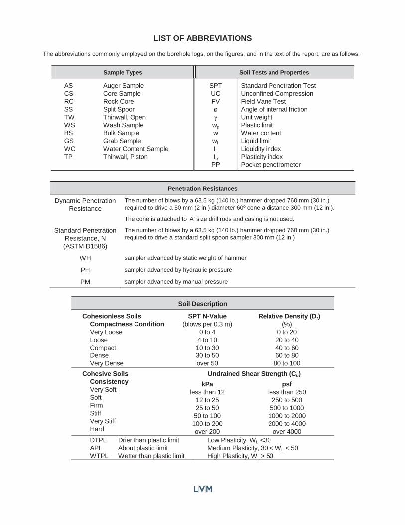
LIST OF ABBREVIATIONS
The abbreviations commonly employed on the borehole logs, on the figures, and in the text of the report, are as follows:
Sample Types Soil Tests and Properties
AS Auger SampleCS Core SampleRC Rock CoreSS Split SpoonTW Thinwall, OpenWS Wash SampleBS Bulk SampleGS Grab SampleWC Water Content SampleTP Thinwall, Piston
SPTUCFV ø
wp
wwL
ILIp
PP
Standard Penetration TestUnconfined CompressionField Vane Test Angle of internal frictionUnit weightPlastic limitWater contentLiquid limitLiquidity indexPlasticity indexPocket penetrometer
Penetration Resistances
Dynamic PenetrationResistance
The number of blows by a 63.5 kg (140 lb.) hammer dropped 760 mm (30 in.) required to drive a 50 mm (2 in.) diameter 60º cone a distance 300 mm (12 in.).
The cone is attached to 'A' size drill rods and casing is not used.
Standard PenetrationResistance, N (ASTM D1586)
The number of blows by a 63.5 kg (140 lb.) hammer dropped 760 mm (30 in.) required to drive a standard split spoon sampler 300 mm (12 in.)
WH sampler advanced by static weight of hammer
PH sampler advanced by hydraulic pressure
PM sampler advanced by manual pressure
Soil Description
Cohesionless Soils Compactness ConditionVery LooseLooseCompactDenseVery Dense
SPT N-Value(blows per 0.3 m)
0 to 44 to 1010 to 3030 to 50over 50
Relative Density (Dr)(%)
0 to 2020 to 4040 to 6060 to 8080 to 100
Cohesive Soils ConsistencyVery SoftSoftFirmStiffVery StiffHard
Undrained Shear Strength (Cu)
kPaless than 12
12 to 2525 to 50
50 to 100100 to 200over 200
psfless than 250
250 to 500500 to 10001000 to 20002000 to 4000
over 4000DTPL Drier than plastic limitAPL About plastic limitWTPL Wetter than plastic limit
Low Plasticity, WL <30Medium Plasticity, 30 < WL < 50High Plasticity, WL > 50
1
2
3
4
5
6
7
8
1
2
3
4
5
6
7
8
Dep
th (
m)
361.21
0.00
360.90
0.30
360.45
0.76
359.69
1.52
358.92
2.29
358.16
3.05
355.11
6.10
353.59
7.62
353.13
8.08
Ele
vati
on
(m
)
Dep
th (
m)
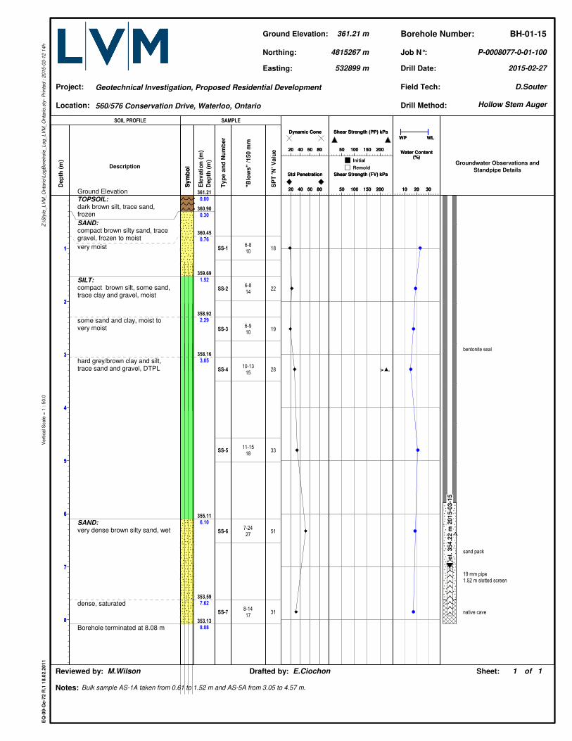
Ground Elevation
TOPSOIL:dark brown silt, trace sand,frozen
SAND:compact brown silty sand, tracegravel, frozen to moist
very moist
SILT:compact brown silt, some sand,trace clay and gravel, moist
some sand and clay, moist tovery moist
hard grey/brown clay and silt,trace sand and gravel, DTPL
SAND:very dense brown silty sand, wet
dense, saturated
Borehole terminated at 8.08 m
Description
Sym
bo
lS
ym
bo
l
Groundwater Observations and
Standpipe Details
el.
354.2
2 m
2015-0
3-1
5
bentonite seal
sand pack
19 mm pipe1.52 m slotted screen
native cave
SS-1
SS-2
SS-3
SS-4
SS-5
SS-6
SS-7
Typ
e a
nd
Nu
mb
er
6-810
6-814
6-910
10-1315
11-1518
7-2427
8-1417
"Blo
ws"
/150 m
m18
22
19
28
33
51
31
SP
T 'N
' V
alu
e
10 20 30
WP WL
Water Content(%)
10 20 30
WP WL
Water Content(%)
20 40 60 80
Dynamic Cone
20 40 60 80
Dynamic Cone
50 100 150 200
Shear Strength (PP) kPa
50 100 150 200
Shear Strength (PP) kPa
20 40 60 80
Std Penetration
20 40 60 80
Std Penetration
50 100 150 200
Shear Strength (FV) kPa
50 100 150 200
Shear Strength (FV) kPa
> .
Drill Date:
Sheet:
2015-02-27
Geotechnical Investigation, Proposed Residential Development
Bulk sample AS-1A taken from 0.61 to 1.52 m and AS-5A from 3.05 to 4.57 m.
P-0008077-0-01-100
of1 1
EQ
-09
-Ge
-72
R.1
18
.02
.20
11
Z:\
Sty
le_
LV
M_
On
tari
o\L
og
Bo
reh
ole
_L
og
_L
VM
_O
nta
rio
.sty
- P
rin
ted
: 2
01
5-0
3-1
2 1
4h
Vert
ical S
cale
= 1
: 5
0.0
Location:
Job N°:
Project:
Drafted by: E.CiochonReviewed by: M.Wilson
Borehole Number:
Notes:
Ground Elevation:
532899 m
Northing:
361.21 m BH-01-15
Easting:
Field Tech:
4815267 m
D.Souter
Drill Method:560/576 Conservation Drive, Waterloo, Ontario
SOIL PROFILE SAMPLE
Initial
Remold
Hollow Stem Auger
1
2
3
4
5
6
7
8
1
2
3
4
5
6
7
8
Dep
th (
m)
358.14
0.00
357.38
0.76
357.07
1.07
355.85
2.29
354.33
3.81
353.57
4.57
352.04
6.10
350.52
7.62
350.06
8.08
Ele
vati
on
(m
)
Dep
th (
m)
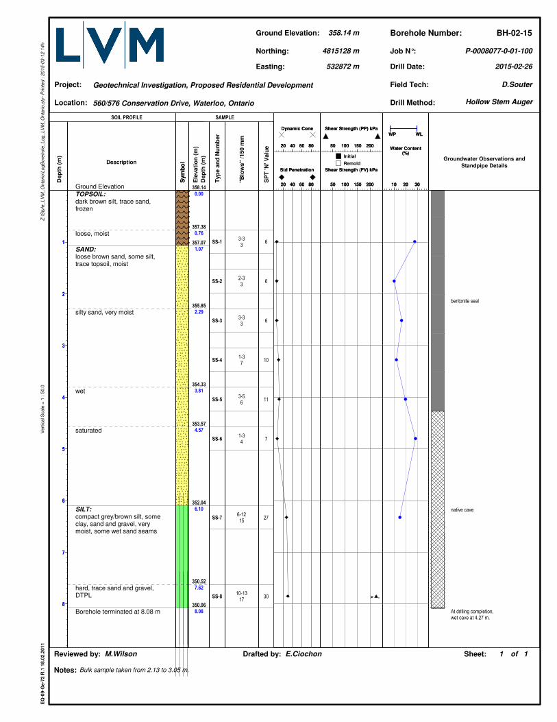
Ground Elevation
TOPSOIL:dark brown silt, trace sand,frozen
loose, moist
SAND:loose brown sand, some silt,trace topsoil, moist
silty sand, very moist
wet
saturated
SILT:compact grey/brown silt, someclay, sand and gravel, verymoist, some wet sand seams
hard, trace sand and gravel,DTPL
Borehole terminated at 8.08 m
Description
Sym
bo
lS
ym
bo
l
Groundwater Observations and
Standpipe Details
bentonite seal
native cave
At drilling completion,wet cave at 4.27 m.
SS-1
SS-2
SS-3
SS-4
SS-5
SS-6
SS-7
SS-8
Typ
e a
nd
Nu
mb
er
3-33
2-33
3-33
1-37
3-56
1-34
6-1215
10-1317
"Blo
ws"
/150 m
m6
6
6
10
11
7
27
30
SP
T 'N
' V
alu
e
10 20 30
WP WL
Water Content(%)
10 20 30
WP WL
Water Content(%)
20 40 60 80
Dynamic Cone
20 40 60 80
Dynamic Cone
50 100 150 200
Shear Strength (PP) kPa
50 100 150 200
Shear Strength (PP) kPa
20 40 60 80
Std Penetration
20 40 60 80
Std Penetration
50 100 150 200
Shear Strength (FV) kPa
50 100 150 200
Shear Strength (FV) kPa
> .
Drill Date:
Sheet:
2015-02-26
Geotechnical Investigation, Proposed Residential Development
Bulk sample taken from 2.13 to 3.05 m.
P-0008077-0-01-100
of1 1
EQ
-09
-Ge
-72
R.1
18
.02
.20
11
Z:\
Sty
le_
LV
M_
On
tari
o\L
og
Bo
reh
ole
_L
og
_L
VM
_O
nta
rio
.sty
- P
rin
ted
: 2
01
5-0
3-1
2 1
4h
Vert
ical S
cale
= 1
: 5
0.0
Location:
Job N°:
Project:
Drafted by: E.CiochonReviewed by: M.Wilson
Borehole Number:
Notes:
Ground Elevation:
532872 m
Northing:
358.14 m BH-02-15
Easting:
Field Tech:
4815128 m
D.Souter
Drill Method:560/576 Conservation Drive, Waterloo, Ontario
SOIL PROFILE SAMPLE
Initial
Remold
Hollow Stem Auger
1
2
3
4
5
6
7
8
1
2
3
4
5
6
7
8
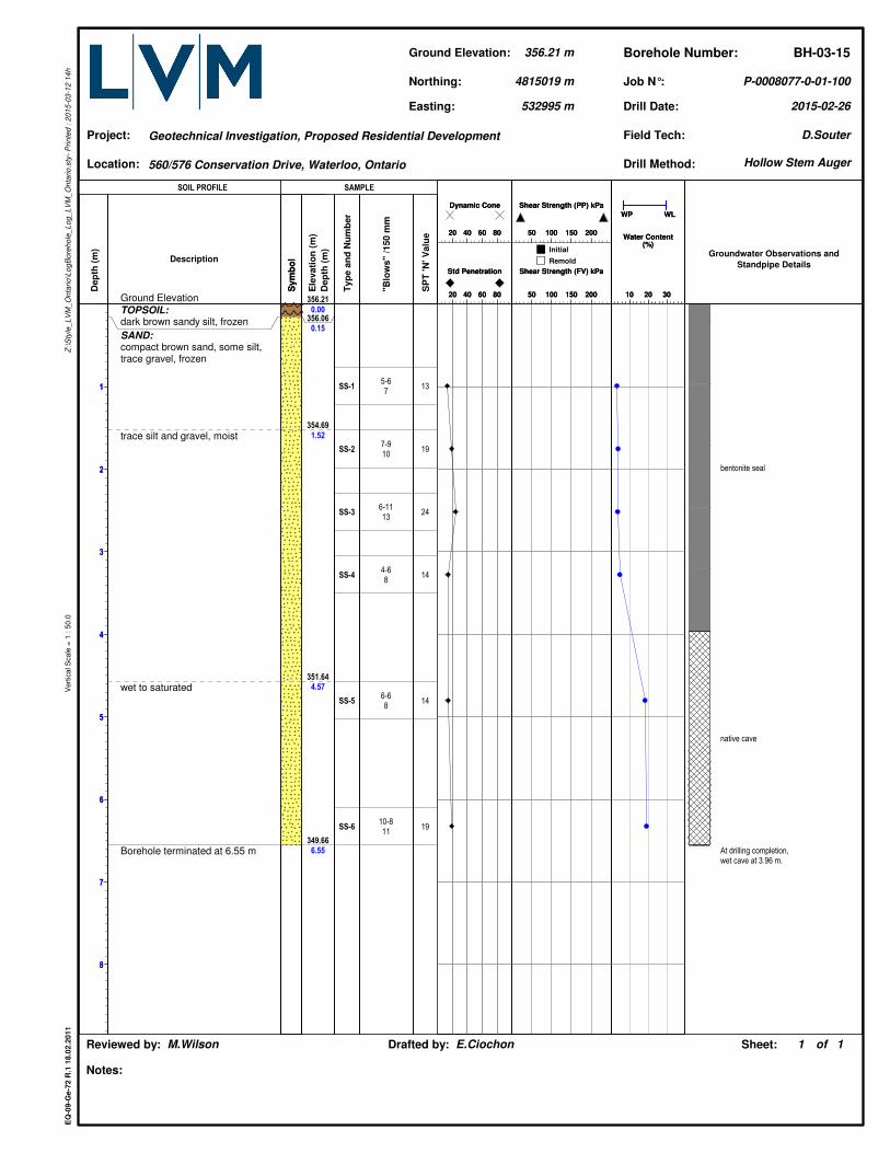
Dep
th (
m)
356.21
0.00
356.06
0.15
354.69
1.52
351.64
4.57
349.66
6.55
Ele
vati
on
(m
)
Dep
th (
m)
Ground Elevation
TOPSOIL:dark brown sandy silt, frozen
SAND:compact brown sand, some silt,trace gravel, frozen
trace silt and gravel, moist
wet to saturated
Borehole terminated at 6.55 m
Description
Sym
bo
lS
ym
bo
l
Groundwater Observations and
Standpipe Details
bentonite seal
native cave
At drilling completion,wet cave at 3.96 m.
SS-1
SS-2
SS-3
SS-4
SS-5
SS-6
Typ
e a
nd
Nu
mb
er
5-67
7-910
6-1113
4-68
6-68
10-811
"Blo
ws"
/150 m
m13
19
24
14
14
19
SP
T 'N
' V
alu
e
10 20 30
WP WL
Water Content(%)
10 20 30
WP WL
Water Content(%)
20 40 60 80
Dynamic Cone
20 40 60 80
Dynamic Cone
50 100 150 200
Shear Strength (PP) kPa
50 100 150 200
Shear Strength (PP) kPa
20 40 60 80
Std Penetration
20 40 60 80
Std Penetration
50 100 150 200
Shear Strength (FV) kPa
50 100 150 200
Shear Strength (FV) kPa
Drill Date:
Sheet:
2015-02-26
Geotechnical Investigation, Proposed Residential Development
P-0008077-0-01-100
of1 1
EQ
-09
-Ge
-72
R.1
18
.02
.20
11
Z:\
Sty
le_
LV
M_
On
tari
o\L
og
Bo
reh
ole
_L
og
_L
VM
_O
nta
rio
.sty
- P
rin
ted
: 2
01
5-0
3-1
2 1
4h
Vert
ical S
cale
= 1
: 5
0.0
Location:
Job N°:
Project:
Drafted by: E.CiochonReviewed by: M.Wilson
Borehole Number:
Notes:
Ground Elevation:
532995 m
Northing:
356.21 m BH-03-15
Easting:
Field Tech:
4815019 m
D.Souter
Drill Method:560/576 Conservation Drive, Waterloo, Ontario
SOIL PROFILE SAMPLE
Initial
Remold
Hollow Stem Auger

1
2
3
4
5
6
7
8
1
2
3
4
5
6
7
8
Dep
th (
m)
351.86
0.00
351.50
0.36
350.34
1.52
348.81
3.05
347.29
4.57
346.68
5.18
343.78
8.08
Ele
vati
on
(m
)
Dep
th (
m)
Ground Elevation
TOPSOIL:dark brown silt, some sand,frozen
SAND:loose brown silty sand, tracegravel, wet
compact brown sand, tracegravel and silt, saturated
SILT TILL:hard grey clayey silt, some sand,trace gravel, APL
very stiff, trace sand and gravel,APL to WTPL
SILT:compact grey silt, some clay andfine sand, saturated
Borehole terminated at 8.08 m
Description
Sym
bo
lS
ym
bo
l
Groundwater Observations and
Standpipe Details
el.
350.9
1 m
2015-0
3-1
5
bentonite seal
sand pack
19 mm pipe3.05 m slotted screen
native cave
SS-1
SS-2
SS-3
SS-4
SS-5
SS-6
SS-7
Typ
e a
nd
Nu
mb
er
2-33
5-56
7-86
4-610
3-67
6-79
5-77
"Blo
ws"
/150 m
m6
11
14
16
13
16
14
SP
T 'N
' V
alu
e
10 20 30
WP WL
Water Content(%)
10 20 30
WP WL
Water Content(%)
20 40 60 80
Dynamic Cone
20 40 60 80
Dynamic Cone
50 100 150 200
Shear Strength (PP) kPa
50 100 150 200
Shear Strength (PP) kPa
20 40 60 80
Std Penetration
20 40 60 80
Std Penetration
50 100 150 200
Shear Strength (FV) kPa
50 100 150 200
Shear Strength (FV) kPa
Drill Date:
Sheet:
2015-02-26
Geotechnical Investigation, Proposed Residential Development
P-0008077-0-01-100
of1 1
EQ
-09
-Ge
-72
R.1
18
.02
.20
11
Z:\
Sty
le_
LV
M_
On
tari
o\L
og
Bo
reh
ole
_L
og
_L
VM
_O
nta
rio
.sty
- P
rin
ted
: 2
01
5-0
3-1
2 1
4h
Vert
ical S
cale
= 1
: 5
0.0
Location:
Job N°:
Project:
Drafted by: E.CiochonReviewed by: M.Wilson
Borehole Number:
Notes:
Ground Elevation:
532751 m
Northing:
351.86 m BH-04-15
Easting:
Field Tech:
4814862 m
D.Souter
Drill Method:560/576 Conservation Drive, Waterloo, Ontario
SOIL PROFILE SAMPLE
Initial
Remold
Hollow Stem Auger
1
2
3
4
5
6
7
8
1
2
3
4
5
6
7
8
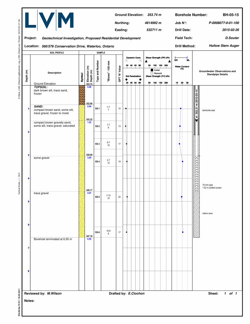
Dep
th (
m)
353.74
0.00
352.90
0.84
352.22
1.52
350.69
3.05
349.17
4.57
347.19
6.55
Ele
vati
on
(m
)
Dep
th (
m)
Ground Elevation
TOPSOIL:dark brown silt, trace sand,frozen
SAND:compact brown sand, some silt,trace gravel, frozen to moist
compact brown gravelly sand,some silt, trace gravel, saturated
some gravel
trace gravel
Borehole terminated at 6.55 m
Description
Sym
bo
lS
ym
bo
l
Groundwater Observations and
Standpipe Details
el.
352.2
1 m
2015-0
3-1
5
bentonite seal
19 mm pipe1.52 m slotted screen
native cave
SS-1
SS-2
SS-3
SS-4
SS-5
SS-6
Typ
e a
nd
Nu
mb
er
7-77
7-76
5-710
3-712
7-1010
15-98
"Blo
ws"
/150 m
m14
13
17
19
20
17
SP
T 'N
' V
alu
e
10 20 30
WP WL
Water Content(%)
10 20 30
WP WL
Water Content(%)
20 40 60 80
Dynamic Cone
20 40 60 80
Dynamic Cone
50 100 150 200
Shear Strength (PP) kPa
50 100 150 200
Shear Strength (PP) kPa
20 40 60 80
Std Penetration
20 40 60 80
Std Penetration
50 100 150 200
Shear Strength (FV) kPa
50 100 150 200
Shear Strength (FV) kPa
Drill Date:
Sheet:
2015-02-26
Geotechnical Investigation, Proposed Residential Development
P-0008077-0-01-100
of1 1
EQ
-09
-Ge
-72
R.1
18
.02
.20
11
Z:\
Sty
le_
LV
M_
On
tari
o\L
og
Bo
reh
ole
_L
og
_L
VM
_O
nta
rio
.sty
- P
rin
ted
: 2
01
5-0
3-1
2 1
4h
Vert
ical S
cale
= 1
: 5
0.0
Location:
Job N°:
Project:
Drafted by: E.CiochonReviewed by: M.Wilson
Borehole Number:
Notes:
Ground Elevation:
532711 m
Northing:
353.74 m BH-05-15
Easting:
Field Tech:
4814992 m
D.Souter
Drill Method:560/576 Conservation Drive, Waterloo, Ontario
SOIL PROFILE SAMPLE
Initial
Remold
Hollow Stem Auger
1
2
3
4
5
6
7
8
1
2
3
4
5
6
7
8
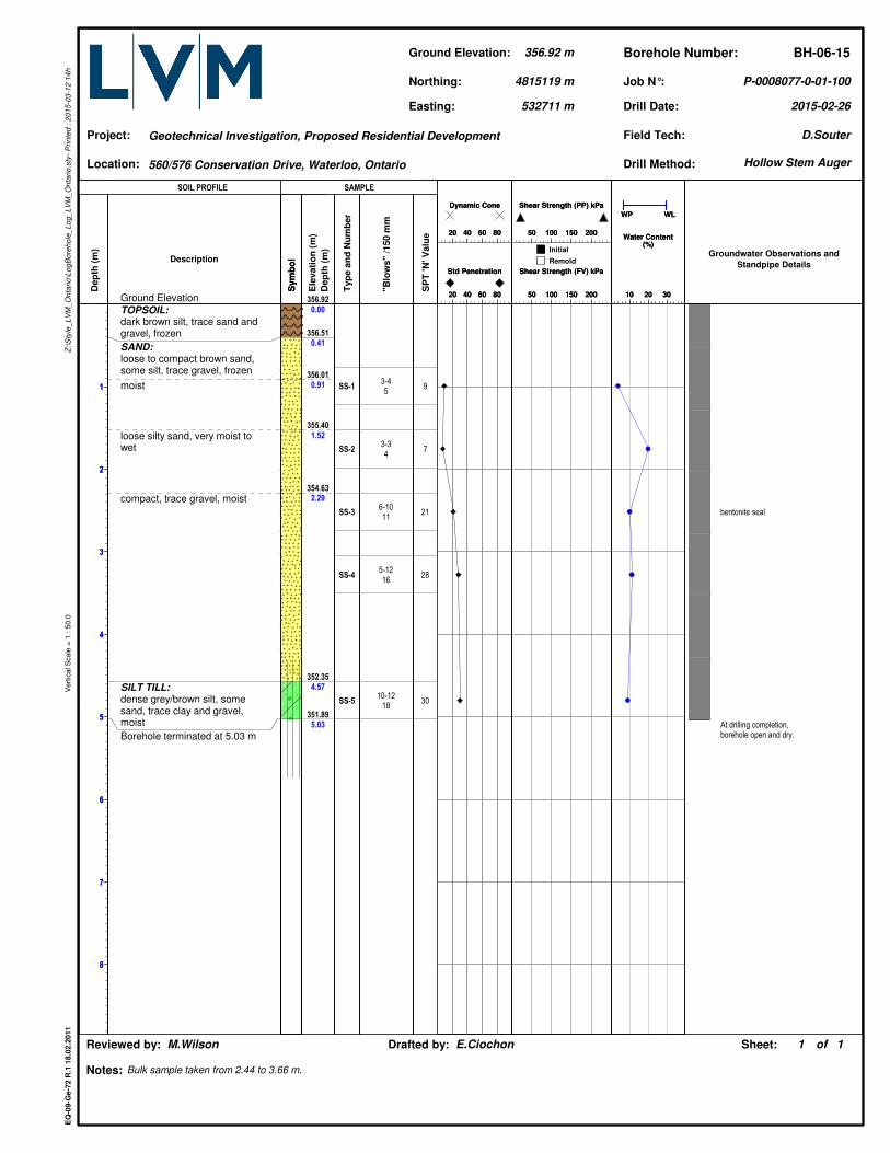
Dep
th (
m)
356.92
0.00
356.51
0.41
356.01
0.91
355.40
1.52
354.63
2.29
352.35
4.57
351.89
5.03
Ele
vati
on
(m
)
Dep
th (
m)
Ground Elevation
TOPSOIL:dark brown silt, trace sand andgravel, frozen
SAND:loose to compact brown sand,some silt, trace gravel, frozen
moist
loose silty sand, very moist towet
compact, trace gravel, moist
SILT TILL:dense grey/brown silt, somesand, trace clay and gravel,moist
Borehole terminated at 5.03 m
Description
Sym
bo
lS
ym
bo
l
Groundwater Observations and
Standpipe Details
bentonite seal
At drilling completion,borehole open and dry.
SS-1
SS-2
SS-3
SS-4
SS-5
Typ
e a
nd
Nu
mb
er
3-45
3-34
6-1011
5-1216
10-1218
"Blo
ws"
/150 m
m9
7
21
28
30
SP
T 'N
' V
alu
e
10 20 30
WP WL
Water Content(%)
10 20 30
WP WL
Water Content(%)
20 40 60 80
Dynamic Cone
20 40 60 80
Dynamic Cone
50 100 150 200
Shear Strength (PP) kPa
50 100 150 200
Shear Strength (PP) kPa
20 40 60 80
Std Penetration
20 40 60 80
Std Penetration
50 100 150 200
Shear Strength (FV) kPa
50 100 150 200
Shear Strength (FV) kPa
Drill Date:
Sheet:
2015-02-26
Geotechnical Investigation, Proposed Residential Development
Bulk sample taken from 2.44 to 3.66 m.
P-0008077-0-01-100
of1 1
EQ
-09
-Ge
-72
R.1
18
.02
.20
11
Z:\
Sty
le_
LV
M_
On
tari
o\L
og
Bo
reh
ole
_L
og
_L
VM
_O
nta
rio
.sty
- P
rin
ted
: 2
01
5-0
3-1
2 1
4h
Vert
ical S
cale
= 1
: 5
0.0
Location:
Job N°:
Project:
Drafted by: E.CiochonReviewed by: M.Wilson
Borehole Number:
Notes:
Ground Elevation:
532711 m
Northing:
356.92 m BH-06-15
Easting:
Field Tech:
4815119 m
D.Souter
Drill Method:560/576 Conservation Drive, Waterloo, Ontario
SOIL PROFILE SAMPLE
Initial
Remold
Hollow Stem Auger
1
2
3
4
5
6
7
8
1
2
3
4
5
6
7
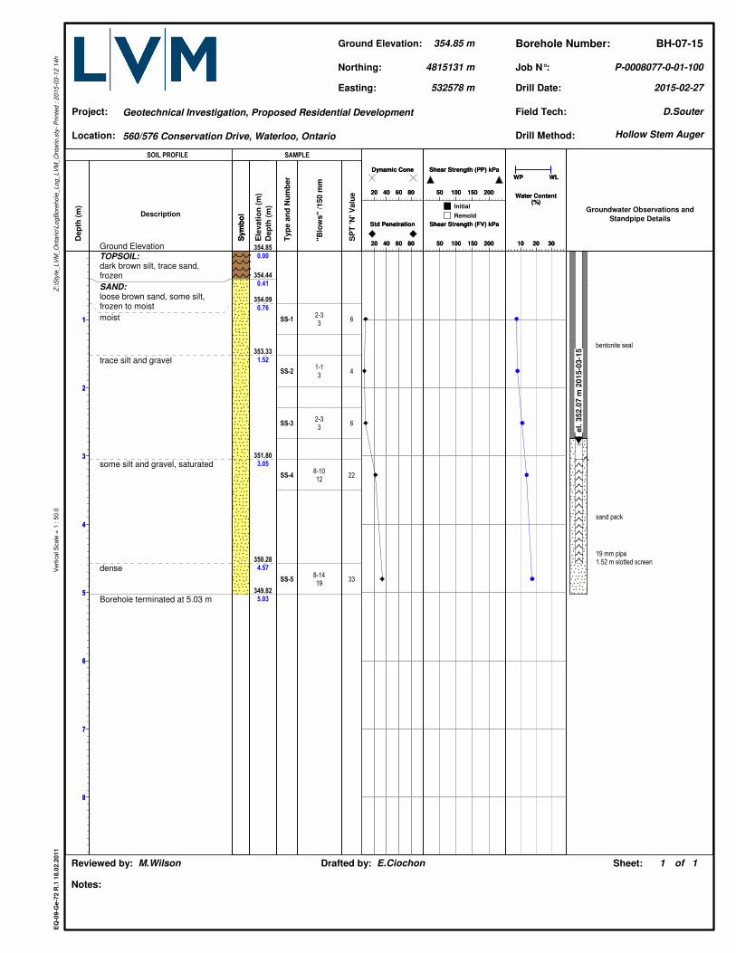
8
Dep
th (
m)
354.85
0.00
354.44
0.41
354.09
0.76
353.33
1.52
351.80
3.05
350.28
4.57
349.82
5.03
Ele
vati
on
(m
)
Dep
th (
m)
Ground Elevation
TOPSOIL:dark brown silt, trace sand,frozen
SAND:loose brown sand, some silt,frozen to moist
moist
trace silt and gravel
some silt and gravel, saturated
dense
Borehole terminated at 5.03 m
Description
Sym
bo
lS
ym
bo
l
Groundwater Observations and
Standpipe Details
el.
352.0
7 m
2015-0
3-1
5
bentonite seal
sand pack
19 mm pipe1.52 m slotted screen
SS-1
SS-2
SS-3
SS-4
SS-5
Typ
e a
nd
Nu
mb
er
2-33
1-13
2-33
8-1012
8-1419
"Blo
ws"
/150 m
m6
4
6
22
33
SP
T 'N
' V
alu
e
10 20 30
WP WL
Water Content(%)
10 20 30
WP WL
Water Content(%)
20 40 60 80
Dynamic Cone
20 40 60 80
Dynamic Cone
50 100 150 200
Shear Strength (PP) kPa
50 100 150 200
Shear Strength (PP) kPa
20 40 60 80
Std Penetration
20 40 60 80
Std Penetration
50 100 150 200
Shear Strength (FV) kPa
50 100 150 200
Shear Strength (FV) kPa
Drill Date:
Sheet:
2015-02-27
Geotechnical Investigation, Proposed Residential Development
P-0008077-0-01-100
of1 1
EQ
-09
-Ge
-72
R.1
18
.02
.20
11
Z:\
Sty
le_
LV
M_
On
tari
o\L
og
Bo
reh
ole
_L
og
_L
VM
_O
nta
rio
.sty
- P
rin
ted
: 2
01
5-0
3-1
2 1
4h
Vert
ical S
cale
= 1
: 5
0.0
Location:
Job N°:
Project:
Drafted by: E.CiochonReviewed by: M.Wilson
Borehole Number:
Notes:
Ground Elevation:
532578 m
Northing:
354.85 m BH-07-15
Easting:
Field Tech:
4815131 m
D.Souter
Drill Method:560/576 Conservation Drive, Waterloo, Ontario
SOIL PROFILE SAMPLE
Initial
Remold
Hollow Stem Auger
1
2
3
4
5
6
7
8
1
2
3
4
5
6
7
8
Dep
th (
m)
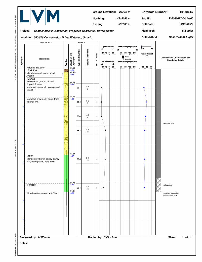
357.56
0.00
357.41
0.15
356.80
0.76
356.04
1.52
352.99
4.57
351.46
6.10
351.01
6.55
Ele
vati
on
(m
)
Dep
th (
m)
Ground Elevation
TOPSOIL:dark brown silt, some sand,frozen
SAND:brown sand, some silt andtopsoil, frozen
compact, some silt, trace gravel,moist
compact brown silty sand, tracegravel, wet
SILT:dense grey/brown sandy clayeysilt, trace gravel, very moist
compact
Borehole terminated at 6.55 m
Description
Sym
bo
lS
ym
bo
l
Groundwater Observations and
Standpipe Details
bentonite seal
native cave
At drilling completion,wet cave at 5.79 m.
SS-1
SS-2
SS-3
SS-4
SS-5
SS-6
Typ
e a
nd
Nu
mb
er
4-65
5-58
4-67
7-1820
8-1916
9-1016
"Blo
ws"
/150 m
m11
13
13
38
35
26
SP
T 'N
' V
alu
e
10 20 30
WP WL
Water Content(%)
10 20 30
WP WL
Water Content(%)
20 40 60 80
Dynamic Cone
20 40 60 80
Dynamic Cone
50 100 150 200
Shear Strength (PP) kPa
50 100 150 200
Shear Strength (PP) kPa
20 40 60 80
Std Penetration
20 40 60 80
Std Penetration
50 100 150 200
Shear Strength (FV) kPa
50 100 150 200
Shear Strength (FV) kPa
Drill Date:
Sheet:
2015-02-27
Geotechnical Investigation, Proposed Residential Development
P-0008077-0-01-100
of1 1
EQ
-09
-Ge
-72
R.1
18
.02
.20
11
Z:\
Sty
le_
LV
M_
On
tari
o\L
og
Bo
reh
ole
_L
og
_L
VM
_O
nta
rio
.sty
- P
rin
ted
: 2
01
5-0
3-1
6 0
9h
Vert
ical S
cale
= 1
: 5
0.0
Location:
Job N°:
Project:
Drafted by: E.CiochonReviewed by: M.Wilson
Borehole Number:
Notes:
Ground Elevation:
532630 m
Northing:
357.56 m BH-08-15
Easting:
Field Tech:
4815292 m
D.Souter
Drill Method:560/576 Conservation Drive, Waterloo, Ontario
SOIL PROFILE SAMPLE
Initial
Remold
Hollow Stem Auger
1
2
3
4
5
6
7
8
1
2
3
4
5
6
7
8
Dep
th (
m)
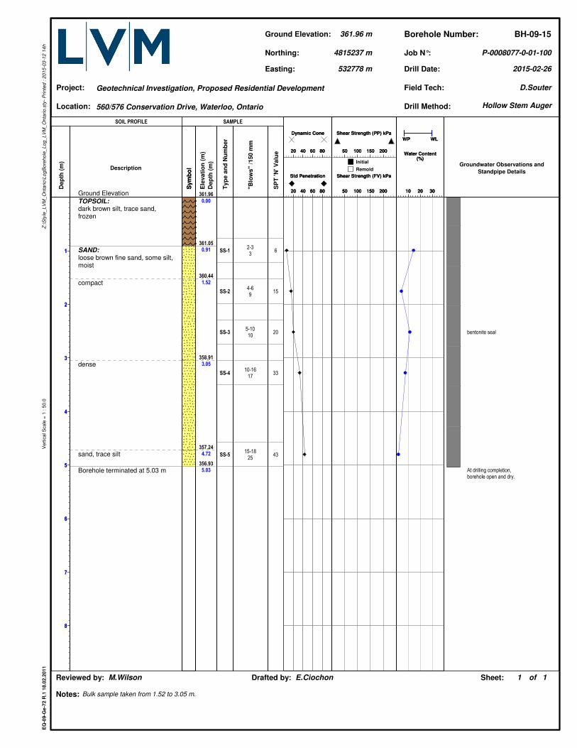
361.96
0.00
361.05
0.91
360.44
1.52
358.91
3.05
357.24
4.72
356.93
5.03
Ele
vati
on
(m
)
Dep
th (
m)
Ground Elevation
TOPSOIL:dark brown silt, trace sand,frozen
SAND:loose brown fine sand, some silt,moist
compact
dense
sand, trace silt
Borehole terminated at 5.03 m
Description
Sym
bo
lS
ym
bo
l
Groundwater Observations and
Standpipe Details
bentonite seal
At drilling completion,borehole open and dry.
SS-1
SS-2
SS-3
SS-4
SS-5
Typ
e a
nd
Nu
mb
er
2-33
4-69
5-1010
10-1617
15-1825
"Blo
ws"
/150 m
m6
15
20
33
43
SP
T 'N
' V
alu
e
10 20 30
WP WL
Water Content(%)
10 20 30
WP WL
Water Content(%)
20 40 60 80
Dynamic Cone
20 40 60 80
Dynamic Cone
50 100 150 200
Shear Strength (PP) kPa
50 100 150 200
Shear Strength (PP) kPa
20 40 60 80
Std Penetration
20 40 60 80
Std Penetration
50 100 150 200
Shear Strength (FV) kPa
50 100 150 200
Shear Strength (FV) kPa
Drill Date:
Sheet:
2015-02-26
Geotechnical Investigation, Proposed Residential Development
Bulk sample taken from 1.52 to 3.05 m.
P-0008077-0-01-100
of1 1
EQ
-09
-Ge
-72
R.1
18
.02
.20
11
Z:\
Sty
le_
LV
M_
On
tari
o\L
og
Bo
reh
ole
_L
og
_L
VM
_O
nta
rio
.sty
- P
rin
ted
: 2
01
5-0
3-1
2 1
4h
Vert
ical S
cale
= 1
: 5
0.0
Location:
Job N°:
Project:
Drafted by: E.CiochonReviewed by: M.Wilson
Borehole Number:
Notes:
Ground Elevation:
532778 m
Northing:
361.96 m BH-09-15
Easting:
Field Tech:
4815237 m
D.Souter
Drill Method:560/576 Conservation Drive, Waterloo, Ontario
SOIL PROFILE SAMPLE
Initial
Remold
Hollow Stem Auger
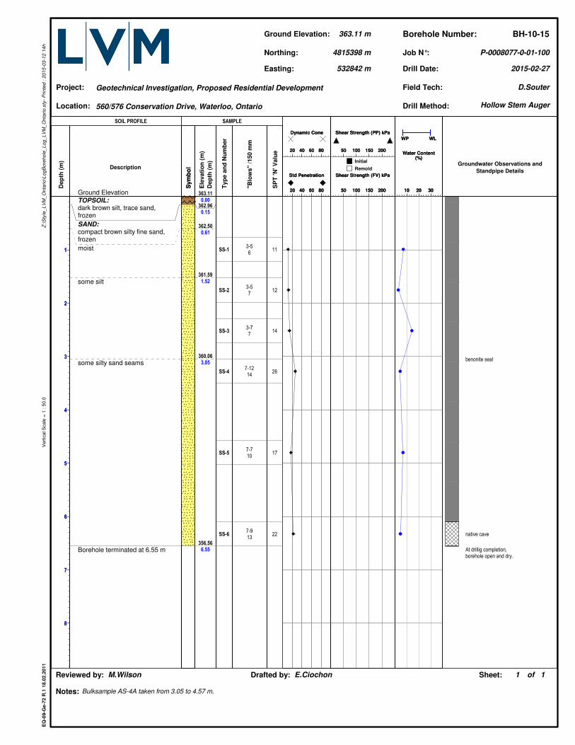
1
2
3
4
5
6
7
8
1
2
3
4
5
6
7
8
Dep
th (
m)
363.11
0.00
362.96
0.15
362.50
0.61
361.59
1.52
360.06
3.05
356.56
6.55
Ele
vati
on
(m
)
Dep
th (
m)
Ground Elevation
TOPSOIL:dark brown silt, trace sand,frozen
SAND:compact brown silty fine sand,frozen
moist
some silt
some silty sand seams
Borehole terminated at 6.55 m
Description
Sym
bo
lS
ym
bo
l
Groundwater Observations and
Standpipe Details
benonite seal
native cave
At drillig completion,borehole open and dry.
SS-1
SS-2
SS-3
SS-4
SS-5
SS-6
Typ
e a
nd
Nu
mb
er
3-56
3-57
3-77
7-1214
7-710
7-913
"Blo
ws"
/150 m
m11
12
14
26
17
22
SP
T 'N
' V
alu
e
10 20 30
WP WL
Water Content(%)
10 20 30
WP WL
Water Content(%)
20 40 60 80
Dynamic Cone
20 40 60 80
Dynamic Cone
50 100 150 200
Shear Strength (PP) kPa
50 100 150 200
Shear Strength (PP) kPa
20 40 60 80
Std Penetration
20 40 60 80
Std Penetration
50 100 150 200
Shear Strength (FV) kPa
50 100 150 200
Shear Strength (FV) kPa
Drill Date:
Sheet:
2015-02-27
Geotechnical Investigation, Proposed Residential Development
Bulksample AS-4A taken from 3.05 to 4.57 m.
P-0008077-0-01-100
of1 1
EQ
-09
-Ge
-72
R.1
18
.02
.20
11
Z:\
Sty
le_
LV
M_
On
tari
o\L
og
Bo
reh
ole
_L
og
_L
VM
_O
nta
rio
.sty
- P
rin
ted
: 2
01
5-0
3-1
2 1
4h
Vert
ical S
cale
= 1
: 5
0.0
Location:
Job N°:
Project:
Drafted by: E.CiochonReviewed by: M.Wilson
Borehole Number:
Notes:
Ground Elevation:
532842 m
Northing:
363.11 m BH-10-15
Easting:
Field Tech:
4815398 m
D.Souter
Drill Method:560/576 Conservation Drive, Waterloo, Ontario
SOIL PROFILE SAMPLE
Initial
Remold
Hollow Stem Auger
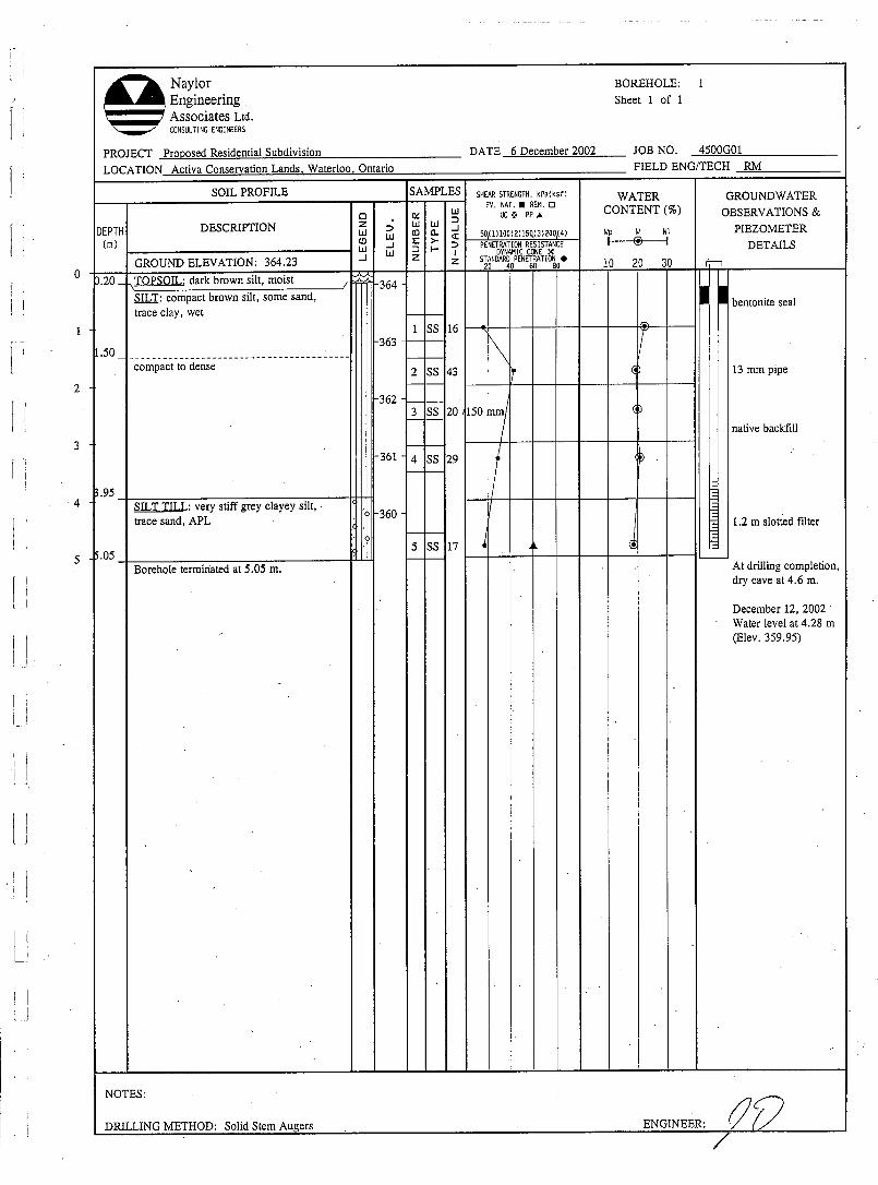
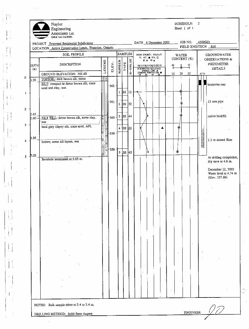
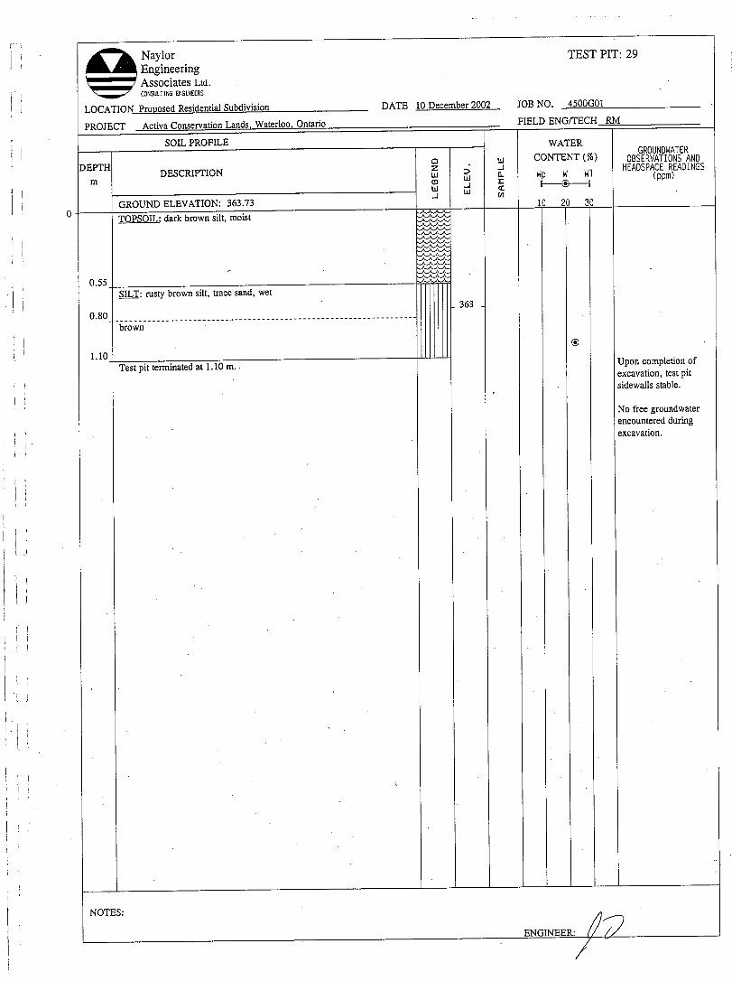
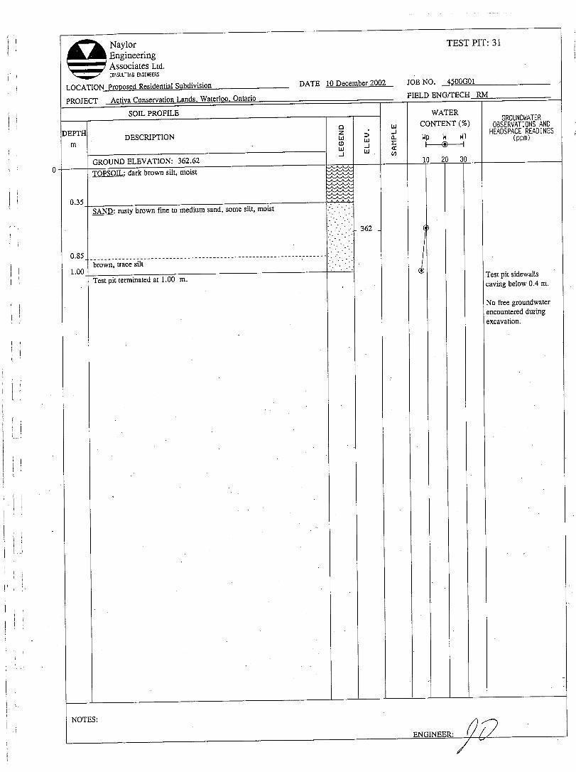
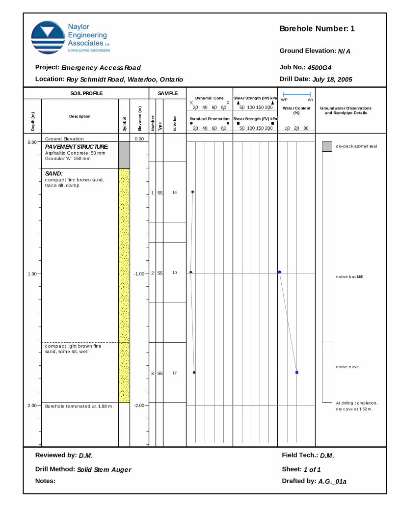
Borehole Number:
Ground Elevation:
Job No.:Project:
Location: Drill Date:
Reviewed by:
Notes:
Field Tech.:
Drill Method: Sheet: 1 of 1Drafted by:
SOIL PROFILE SAMPLE
Dept
h (m
)
0.00
1.00
2.00
Description
Sym
bol
Elev
atio
n (m
)
Num
ber
Type
N-V
alue
Water Content(%)
Groundwater Observationsand Standpipe Details
WP WL
1
N/A
4500G4Emergency Access Road
Roy Schmidt Road, Waterloo, Ontario July 18, 2005
Ground Elevation
PAVEMENT STRUCTURE:Asphaltic Concrete: 50 mmGranular 'A': 150 mm
SAND:compact fine brown sand, trace silt, damp
compact light brown fine sand, some silt, wet
Borehole terminated at 1.98 m.
0.00
-1.00
-2.00
1
2
3
SS
SS
SS
14
10
17
20 40 60 80
Standard Penetration
20 40 60 80
Dynamic Cone
50 100 150 200
Shear Strength (FV) kPa
50 100 150 200
Shear Strength (PP) kPa
10 20 30
dry-pack asphalt seal
native backfill
native cave
At drilling completion,dry cave at 1.52 m.
D.M. D.M.
Solid Stem Auger
A.G._01a
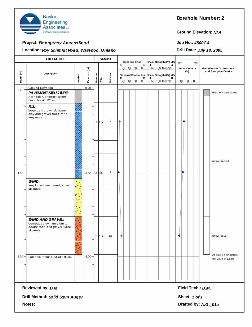
Borehole Number:
Ground Elevation:
Job No.:Project:
Location: Drill Date:
Reviewed by:
Notes:
Field Tech.:
Drill Method: Sheet: 1 of 1Drafted by:
SOIL PROFILE SAMPLE
Dept
h (m
)
0.00
1.00
2.00
Description
Sym
bol
Elev
atio
n (m
)
Num
ber
Type
N-V
alue
Water Content(%)
Groundwater Observationsand Standpipe Details
WP WL
2
N/A
4500G4Emergency Access Road
Roy Schmidt Road, Waterloo, Ontario July 18, 2005
Ground Elevation
PAVEMENT STRUCTURE:Asphaltic Concrete: 40 mmGranular 'A': 125 mm
FILL:loose dark brown silt, some clay and gravel, trace sand, very moist
SAND:very loose brown sand, some silt, moist
SAND AND GRAVEL:compact brown medium to coarse sand and gravel, trace silt, moist
Borehole terminated at 1.98 m.
0.00
-1.00
-2.00
1
2
3
SS
SS
SS
7
4
13
20 40 60 80
Standard Penetration
20 40 60 80
Dynamic Cone
50 100 150 200
Shear Strength (FV) kPa
50 100 150 200
Shear Strength (PP) kPa
10 20 30
dry-pack asphalt seal
native backfill
native cave
At drilling completion,dry cave at 1.52 m.
D.M. D.M.
Solid Stem Auger
A.G._01a
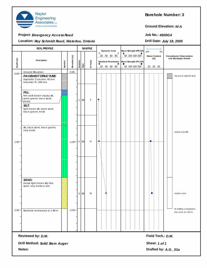
Borehole Number:
Ground Elevation:
Job No.:Project:
Location: Drill Date:
Reviewed by:
Notes:
Field Tech.:
Drill Method: Sheet: 1 of 1Drafted by:
SOIL PROFILE SAMPLE
Dept
h (m
)
0.00
1.00
2.00
Description
Sym
bol
Elev
atio
n (m
)
Num
ber
Type
N-V
alue
Water Content(%)
Groundwater Observationsand Standpipe Details
WP WL
3
N/A
4500G4Emergency Access Road
Roy Schmidt Road, Waterloo, Ontario July 18, 2005
Ground Elevation
PAVEMENT STRUCTURE:Asphaltic Concrete: 40 mmGranular 'A': 205 mm
FILL:firm dark brown clayey silt, some gravel, trace sand, damp
SILT:light brown silt, some sand, trace gravel, moist
silt, trace sand, trace gravel, very moist
SAND:dense light brown silty fine sand, very moist to wet
Borehole terminated at 1.98 m.
0.00
-1.00
-2.00
1
2
3
SS
SS
SS
8
10
39
20 40 60 80
Standard Penetration
20 40 60 80
Dynamic Cone
50 100 150 200
Shear Strength (FV) kPa
50 100 150 200
Shear Strength (PP) kPa
10 20 30
dry-pack asphalt seal
native backfill
native cave
At drilling completion,dry cave at 1.52 m.
D.M. D.M.
Solid Stem Auger
A.G._01a
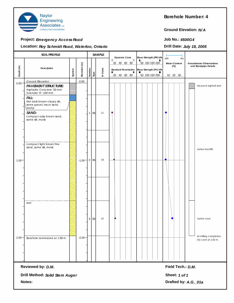
Borehole Number:
Ground Elevation:
Job No.:Project:
Location: Drill Date:
Reviewed by:
Notes:
Field Tech.:
Drill Method: Sheet: 1 of 1Drafted by:
SOIL PROFILE SAMPLE
Dept
h (m
)
0.00
1.00
2.00
Description
Sym
bol
Elev
atio
n (m
)
Num
ber
Type
N-V
alue
Water Content(%)
Groundwater Observationsand Standpipe Details
WP WL
4
N/A
4500G4Emergency Access Road
Roy Schmidt Road, Waterloo, Ontario July 18, 2005
Ground Elevation
PAVEMENT STRUCTURE:Asphaltic Concrete: 50 mmGranular 'A': 100 mm
FILL:firm dark brown clayey silt, some gravel, trace sand, damp
SAND:compact rusty brown sand, some silt, moist
compact light brown fine sand, some silt, moist
wet
Borehole terminated at 1.98 m.
0.00
-1.00
-2.00
1
2
3
SS
SS
SS
11
18
22
20 40 60 80
Standard Penetration
20 40 60 80
Dynamic Cone
50 100 150 200
Shear Strength (FV) kPa
50 100 150 200
Shear Strength (PP) kPa
10 20 30
dry-pack asphalt seal
native backfill
native cave
At drilling completion,dry cave at 1.52 m.
D.M. D.M.
Solid Stem Auger
A.G._01a
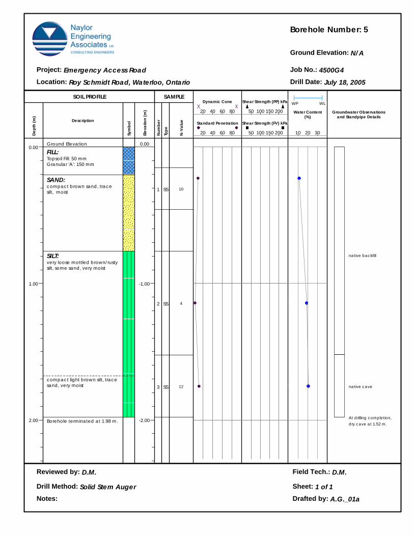
Borehole Number:
Ground Elevation:
Job No.:Project:
Location: Drill Date:
Reviewed by:
Notes:
Field Tech.:
Drill Method: Sheet: 1 of 1Drafted by:
SOIL PROFILE SAMPLE
Dept
h (m
)
0.00
1.00
2.00
Description
Sym
bol
Elev
atio
n (m
)
Num
ber
Type
N-V
alue
Water Content(%)
Groundwater Observationsand Standpipe Details
WP WL
5
N/A
4500G4Emergency Access Road
Roy Schmidt Road, Waterloo, Ontario July 18, 2005
Ground Elevation
FILL:Topsoil Fill: 50 mmGranular 'A': 150 mm
SAND:compact brown sand, trace silt, moist
SILT:very loose mottled brown/rusty silt, some sand, very moist
compact light brown silt, trace sand, very moist
Borehole terminated at 1.98 m.
0.00
-1.00
-2.00
1
2
3
SS
SS
SS
10
4
12
20 40 60 80
Standard Penetration
20 40 60 80
Dynamic Cone
50 100 150 200
Shear Strength (FV) kPa
50 100 150 200
Shear Strength (PP) kPa
10 20 30
native backfill
native cave
At drilling completion,dry cave at 1.52 m.
D.M. D.M.
Solid Stem Auger
A.G._01a

Appendix 3 Figures
Figures 1: Particle Size Distribution Analyses
Figures 2 and 3: Standard Proctor Moisture-Density Test Results
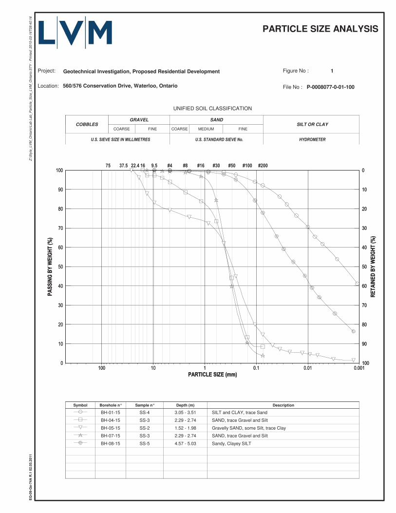
SILT OR CLAYSANDGRAVELCOBBLES
FINEMEDIUMCOARSEFINECOARSE
UNIFIED SOIL CLASSIFICATION
Symbol Borehole n° Sample n° Depth (m) Description
BH-01-15 SS-4 3.05 - 3.51 SILT and CLAY, trace Sand
BH-04-15 SS-3 2.29 - 2.74 SAND, trace Gravel and Silt
BH-05-15 SS-2 1.52 - 1.98 Gravelly SAND, some Silt, trace Clay
BH-07-15 SS-3 2.29 - 2.74 SAND, trace Gravel and Silt
BH-08-15 SS-5 4.57 - 5.03 Sandy, Clayey SILT
PARTICLE SIZE ANALYSIS
Location: 560/576 Conservation Drive, Waterloo, Ontario
Z:\S
tyle
_LV
M_O
ntar
io\L
ab L
ab_P
artic
le_S
ize_
LVM
_Ont
ario
.ST
Y -
Prin
ted:
201
5-03
-16T
09:4
0:16
Project:
EQ
-09-
Ge-
74A
R.1
02.
03.2
011
File No : P-0008077-0-01-100
Figure No : 1Geotechnical Investigation, Proposed Residential Development
COBBLES SILT OR CLAY
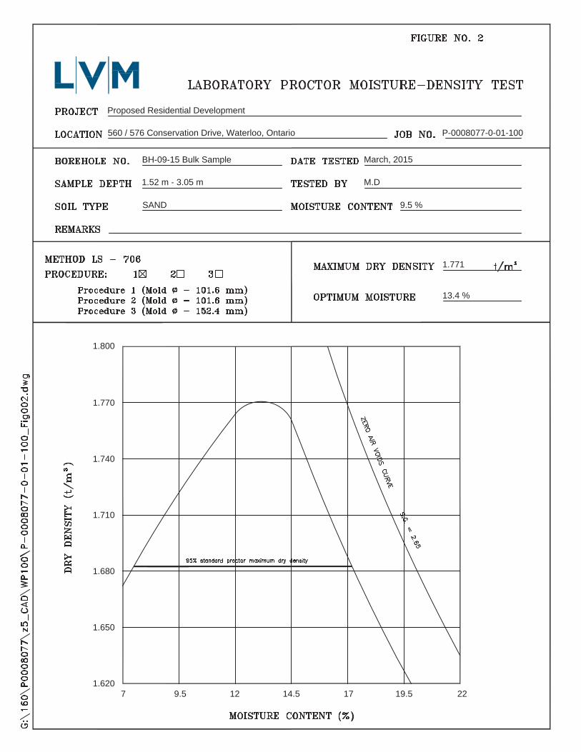
Proposed Residential Development
560 / 576 Conservation Drive, Waterloo, Ontario P-0008077-0-01-100
BH-09-15 Bulk Sample
1.52 m - 3.05 m
SAND
March, 2015
M.D
9.5 %
1.771
13.4 %
1.800
1.770
1.740
1.710
1.680
1.650
1.6207 9.5 12 14.5 17 19.5 22
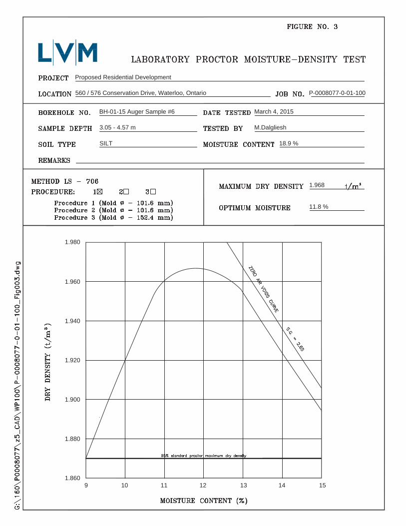
Proposed Residential Development
560 / 576 Conservation Drive, Waterloo, Ontario P-0008077-0-01-100
BH-01-15 Auger Sample #6
3.05 - 4.57 m
SILT
March 4, 2015
M.Dalgliesh
18.9 %
1.968
11.8 %
1.980
1.960
1.940
1.920
1.900
1.880
1.8609 10 11 12 13 14 15

LVM, a division of EnGlobe Corp.