Embed Size (px)
Citation preview

Rev 7/2/14 Part # 11410189
REEL E-Z
Portable Sampling System
Installation and Operation Manual

1
TABLE OF CONTENTS
Section 1: System Description .............................................................................................. 3
Initial Inspection and Handling .................................................................................... 3
Features ...................................................................................................................... 3
Section 2: System Installation & Operation .......................................................................... 4
Horizontal Installation and Operation .......................................................................... 4
Vertical Installation & Operation .................................................................................. 6
Decontamination ....................................................................................................... 10
Pump Decontamination ............................................................................................. 10
Section 3: System Maintenance ......................................................................................... 11
Section 4: System Troubleshooting .................................................................................... 12
Motor Winding Test ................................................................................................... 12
Insulation Resistance Test ........................................................................................ 13
Checking the Impellers for Wear ............................................................................... 13
Replacing Motor Fluid ............................................................................................... 14
Checking the Converter Cable .................................................................................. 14
Section 5: Redi-Flo Variable Frequency Drive .................................................................... 15
Operating Conditions ................................................................................................ 15
Overview ................................................................................................................... 16
Troubleshooting Guide to Error Messages ............................................................... 20
Safety Issue Using the VFD Pump Controller ........................................................... 23
Section 6: System Specifications ....................................................................................... 24
Pump Specifications .................................................................................................. 24
Reel System Specifications: ...................................................................................... 24
HAPPY HOSE! Cable Specifications ......................................................................... 25
VFD Technical Specifications ..................................................................................... 26
The Warranty ...................................................................................................................... 29

2
NOTE
DOCUMENTATION CONVENTIONS
This document uses the following conventions to present information:
An exclamation point icon indicates a WARNING of a situation
or condition that could lead to personal injury or death. You should not proceed until you read and thoroughly understand the WARNING message.
WARNING
CAUTION
A raised hand icon indicates CAUTION information that relates
to a situation or condition that could lead to equipment malfunction or damage. You should not proceed until you read
and thoroughly understand the CAUTION message.
A note icon indicates NOTE information. Notes provide
additional or supplementary information about an activity or concept.

3
Section 1: System Description
The patented REEL E-Z Sampling System has been especially designed for the
Grundfos Redi-Flo2 electrical submersible pump. With the REEL E-Z Portable Sampling
System, the tasks of installing, operating, and storing the Redi-Flo2 are made as simple
and “E-Z” as possible. Please take time to carefully read this manual if unfamiliar with
this product.
Initial Inspection and Handling
Upon receipt of your new system, inspect the shipping package for damage. If any
damage is apparent, contact the carrier and immediately file a claim with the carrier.
Check the cable length to make sure the appropriate amount of cable was included and
that the following items were included: a REEL E-Z converter cable, a PTFE or PVC
sampling hose, and an operating handle.
Features
LOCKING PIN
AND HANDLE
NEMA-6 RATED
ELECTRICAL
CONNECTIONS
PROTECTIVE
ROLLER
HAPPY HOSE!
GRUNDFOS
REDI-FLO2 PUMP
Figure 1: Reel E-Z Features

4
Section 2: System Installation & Operation
The REEL E-Z was designed to be installed either horizontally for flush mount wells or
vertically on the well or protective well casings. The following is a step-by-step
procedure for both installation orientations.
Horizontal Installation and Operation
Step 1
Install the operating handle onto the reel. Push the quick release pin into the hole on
the side of the handle to lock in place.
Step 2
Position the REEL E-Z over the well opening, making sure the forward edge of the roller
is in line with the center of the well. Ideally, the Happy Hose! should roll off the roller
down the center of the well. Avoid scraping the Happy Hose! on the well casing or over
sharp edges, this could result in damage. (Figure 2)
Step 3
Unlock the reel by pulling the pin lock mechanism outward and turning. Remove the
pump from the pump holster by pulling upward on the pump lock knob and gently
sliding the pump out of the holster.
Figure 2: Positioning the Reel E-Z
Figure 3: Unlocking Pump Holster Pin

5
Figure 5: Electrical Connections
Step 4
While holding the operating handle in place, position the pump inside the well. DO NOT
LET THE PUMP “FREE WELL” - damage may result. Using the operating handle,
gently reel the pump down the well to the required installation depth. For user
convenience, the cable is marked every 5 feet.
Step 5
Once the pump has been lowered to the desired depth, lock the reel in place with the pin
lock. (Figure 4)
Step 6
Remove the protective receptacle cap on the electrical box located on the side of the
reel. Connect the converter cord to the electrical box. Connect the other end of the
cord to the converter. (Figure 5)
Figure 4: Locking Pin
Do not power up the converter until the converter cord is
connected. If you are not familiar with the converter, please
read the Redi-Flo Variable Performance Pumps manual for
proper operation. If using VFD, see safety warning in system
troubleshooting.
WARNING
6
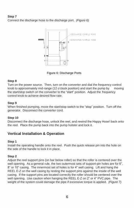
Step 7
Connect the discharge hose to the discharge port. (Figure 6)
Step 8
Turn on the power source. Then, turn on the converter and dial the frequency control
knob to approximately mid-range (12 o’clock position) and start the pump by moving
the start/stop switch on the converter to the “start” position. Adjust the frequency
control knob to achieve desired flow rate.
Step 9
When finished pumping, move the start/stop switch to the “stop” position. Turn off the
generator. Disconnect the converter cord.
Step 10
Disconnect the discharge hose, unlock the reel, and rewind the Happy Hose! back onto
the reel. Place the pump back into the pump holster and lock it.
Vertical Installation & Operation
Step 1
Install the operating handle onto the reel. Push the quick release pin into the hole on
the side of the handle to lock it in place.
Step 2
Adjust the reel support pins (on bar below roller) so that the roller is centered over the
well opening. As a general rule, the two outermost sets of support-pin holes are for 6”,
8” or 10” casing. The innermost set of holes is for 4” well casing. Lift and hang the
REEL E-Z on the well casing by resting the support pins against the inside of the well
casing. If the support pins are located correctly the roller should be centered over the
well opening. Use caution when hanging the REEL E-Z on 2” or 4” PVC pipe. The
weight of the system could damage the pipe if excessive torque is applied. (Figure 7)
Figure 6: Discharge Ports

7
Step 3
Unlock the reel by pulling the pin lock mechanism outward and turning. Remove the
pump from the holster by pulling upward on the pump lock knob and gently sliding the
pump out. (Figure 8)
Step 4
While holding the operating handle in place, position the pump inside the well. DO NOT
LET THE PUMP “FREE WELL” - damage may result. Using the operating handle,
gently reel the pump down the well to the required installation depth. For user
convenience, the cable is marked every 5 feet.
Figure 7: Positioning the Reel E-Z
Figure 8: Unlocking the Pin Lock

8
Step 5
Once the pump has been lowered to the desired depth, lock the reel in place with the
pin lock. (Figure 9)
Step 6
Remove the protective receptacle cap on the electrical box, located on the side of the
reel. Connect the converter cord to the electrical box. Connect the other end of the
cord to the converter. (Figure 10)
Figure 9: Pin-locking the Reel
Do not power up the converter until the converter cord is
connected. If you are not familiar with the converter, please
read the Redi-Flo Variable Performance Pumps manual for
proper operation. If using VFD, see safety warning in system
troubleshooting.
WARNING
Figure 10: Electrical Connections

9
Step 7
Connect the discharge hose to the discharge port. (Figure 11)
Step 8
Turn on the power source. Then, turn on the converter and dial the frequency control
knob to approximately mid-range (12 o’clock position) and start the pump by moving
the start/stop switch on the converter to the “start” position. Adjust the frequency
control knob to achieve desired flow rate.
Step 9
When finished pumping, move the start/stop switch to the “stop” position. Turn off the
generator. Disconnect the converter cord.
Step 10
Disconnect the discharge hose, unlock the reel, and rewind the Happy Hose! onto the
reel. Place the pump back into the pump holster and lock it.
Figure 11: Discharge Port

10
Decontamination
The REEL E-Z was designed to make the decontamination process as easy as possible.
To decontaminate, simply hand wash the system or use a pressure washer to clean the
outside surfaces of the system. To decontaminate the Happy Hose!, either back flush
the Happy Hose! with a non-abrasive detergent & hot water via the discharge port or
simply pump the detergent solution as you would normally pump fluid with the pump and
rinse with deionized water.
Pump Decontamination
The following section describes how to replace the motor fluid in the Grundfos pump:
Make sure the pump is not connected to the converter or any power source. Turn the
pump upside down. Using a flat screwdriver, remove the filling screw on the bottom of
the motor. Empty the water from the motor and refill with deionized water with the
syringe that was included with the Redi-Flo2 pump. The water level should be even
with the bottom of the screw hole. Replace and tighten the filling screw. Turn the
pump over several times and remove the pump filling screw to remove any trapped air.
Add more water if needed. Replace the filling screw and tighten.

11
Section 3: System Maintenance
The REEL E-Z System requires minimal maintenance due to the specially designed
features. The pump holster, cable roller, and heavy duty frame help to give maximum
protection to the Redi-Flo2 and Happy Hose! from damage and wear when installing
and operating the system.
The following list will ensure proper care for the REEL E-Z System:
1. Don’t store the system in sub-freezing temperatures - will result in damage.
2. Periodically inspect the Happy Hose! cable for abrasion, especially at the pump
end.
3. Inspect the reel bearings periodically for signs of wear. If the reel wobbles
unnecessarily, most likely it’s time to replace the bearing set.
4. Avoid pumping in sandy or silty conditions.

12
Section 4: System Troubleshooting
If you are experiencing other problems than mentioned below, please call Geotech Technical Support for immediate assistance, (800) 833-7958.
If the pump is operating at a decreased capacity and the impeller assembly
components (impellers, guide, vanes, etc.) do not appear to be the cause, the motor
should be checked. A checklist of things to examine includes:
• Check the fluid level inside the motor. Replace and refill as necessary — see “Replacing Motor Fluid” in Section 4.
• Inspect the outside of the motor for cracks, dents, etc.
• Remove the Inlet Screen, Pump Housing, and the impeller assembly (see
Figure 14). Try to spin the motor shaft by hand. It should spin freely. If it does
not, the motor must be replaced.
Motor Winding Test This test checks for a short or open circuit in the pump and/or the motor leads. Place
the pump in water. Using an Ohm meter, measure resistance between any two power
leads (see test below). The measurement should be 3 to 7 ohms depending on
system length. The readings should be the same between any set of power leads. If
the readings are zero, there is a short circuit in the pump or there is a set of nicked
power lead wires. If the readings are greater, there is a cut motor lead.
• Details of this test are as follows:
A. Turn off the power and unplug the REEL E-Z from
the converter.
B. Using an Ohm meter, set the scale to R X 1. Zero-
adjust the meter and measure the resistance between
any two power conducting leads (prongs on the motor
lead plug). Compare the obtained reading to the value
in the following table:
Lead Length Ohm Value Lead Length Ohm Value
0 Feet 3.0 - 3.5 150 ft 4.8 - 5.3
50 ft 3.6 - 4.1 175 ft 5.1 - 5.6
75 ft 3.9 - 4.4 200 ft 5.4 - 5.9
100 ft 4.2 - 4.7 250 ft 6.0 - 6.5
125 ft 4.5 - 5.0 300 ft 6.6 - 7.1
C. If the Ohm value is too low, the motor may be shorted. If too high, the motor
windings or the leads may be open.
Figure 12

13
Insulation Resistance Test This test checks for a short to ground in the pump and/or the motor leads. Place the
pump in water. Using an Ohm meter, measure the resistance between the ground lead
and each power lead (see figure 13). The resistance to each power lead should be
greater than 2 meg ohms. If the resistance is less than 2 meg ohms, the pump is
defective or there is a nicked/cut motor lead.
Checking the Impellers for Wear If pump performance decreases, the impellers may need to be replaced or cleaned.
The Redi-Flo2 can be dismantled and reassembled quickly and easily by referring to
the diagram to the right.
1. Dismantling -- Periodically, it will be necessary to check the pump for
impeller wear.
A. Disconnect all power to the REEL E-Z.
B. Remove the discharge hose.
C. Remove the Intake Screen Screw.
D. Carefully pull the screen up. Take care not to nick any motor leads.
E. Unscrew the pump housing.
F. The impeller components can now be inspected.
There is no recommended preventative maintenance for pump components. Reduced
pump performance may be indicative of wear, especially if pumping suspended solids.
Disassemble the pump end impeller assembly (see figure 14, page 12) and examine for
wear according to the following:
Impellers --- should show no visible wear Guide
vane --- should show no visible wear
Wear ring -- minimum thickness should never be less than 1.0mm
2. Re-assembly (refer to figure 14)
A. Make sure the REEL E-Z system is not connected to the converter.
B. Return the impeller assembly to the shaft in the proper order.
C. Screw the Pump Housing back onto the top of the pump. If all the
impellers and chambers were replaced correctly, the Pump Housing should
screw on easily. Hand tighten.
D. Slip the Inlet Screen back over the Pump Housing. Screw the Set Screw
back into the Inlet Screen.
Figure 13: Using an Ohm Meter

14
Wear
Spacer
Wear
Spacer
Set
Shaft
Pump
Guide
Impeller
Wear
Guide
Impeller
Wear
Inlet
Replacing Motor Fluid Whenever any maintenance is done on the pump, the
motor fluid should be replaced. If the pump is moved from
well-to-well, it should be thoroughly decontaminated prior to
being installed in the next well. In addition to cleaning the
individual components inside and outside, the water in the
pump motor should be replaced using the syringe that came
with the pump. This can be accomplished through the
following steps:
1. Disconnect REEL E-Z system and converter from
power source.
2. Turn the pump and motor upside down.
3. Use a flathead screwdriver to remove the filling screw
on the bottom of the motor.
4. Empty the water from the motor and refill the
reservoir using contaminant-free water and the
syringe that came with the REEL E-Z. The water
level should be even with the bottom edge of the
screw hole.
5. Replace and tighten the filling screw.
6. Turn the pump over several times, then remove the
filling screw again to let any trapped air escape (if air
is left inside the motor, the life of the motor will be
shortened). Add more water, if necessary. Repeat
steps 4, 5, & 6 if necessary.
7. Replace and tighten the filling screw.
Checking the Converter Cable To test the converter cable, use an Ohm meter and check for
continuity between connectors for each wire. To do this,
select any one wire in the connector at one end of the cable
and connect it to the Ohm meter. Connect the other end of
the Ohm meter to the same wire at the other end of the
cable. Do this for all four wires. The Ohm meter will show if
there is a short in any of the wires - (see Figure 15).
Filling Motor
Figure 14: Pump
Assembly
Figure 15: Checking the Converter Cable

15
Section 5: Redi-Flo Variable Frequency Drive
Operating Conditions
To ensure the Redi-Flo Variable Performance Pumping system operates properly,
follow these guidelines:
• The Redi-Flo2® or Redi-Flo4™ pump must be installed vertically with the
discharge end pointed upwards.
• The electrical voltage supply to the Redi-Flo VFD must always be within
+ or - 10% of the specified power supply (103.5 - 126.5 VAC at 115V
connection or 207 - 253 VAC at 230V).
• For best performance when operating on a generator, 115V generators should
be set at 120V without load and 230V generators should be set at 240V without
load. Use a separate meter to set voltage; do not rely on built-in meters found on
generators. Verify generator voltage stays within tolerance at full load.
• WARNING: DO not let the generator run out of gas while powering up the
VFD. If it surges and creates excessive voltage, internal VFD damage could
result.
• The pump and motor must always be completely submerged in fluid to ensure
lubrication and cooling of the motor.
• The temperature of the fluid being pumped should be according to the technical
specifications shown in the motor specifications.
• The installation depth of the pump should always be at least three feet below the
maximum drawdown level of the well.
• Redi-Flo pumps are not recommended for well development or pumping fluid
containing abrasives.
• Redi-Flo2® pumps are not recommended for continuous operation applications.
• The warranty of the Redi-Flo pumps will be void if other than the Redi-Flo VFD is
used or if corrosive fluids are pumped.
• The service life of dedicated Redi-Flo pumps may be compromised if the
ambient water quality exceeds one or more of the following values:
pH<5
DO>2 ppm H2S>1 ppm
CL->500 ppm TDS>1000 ppm
16
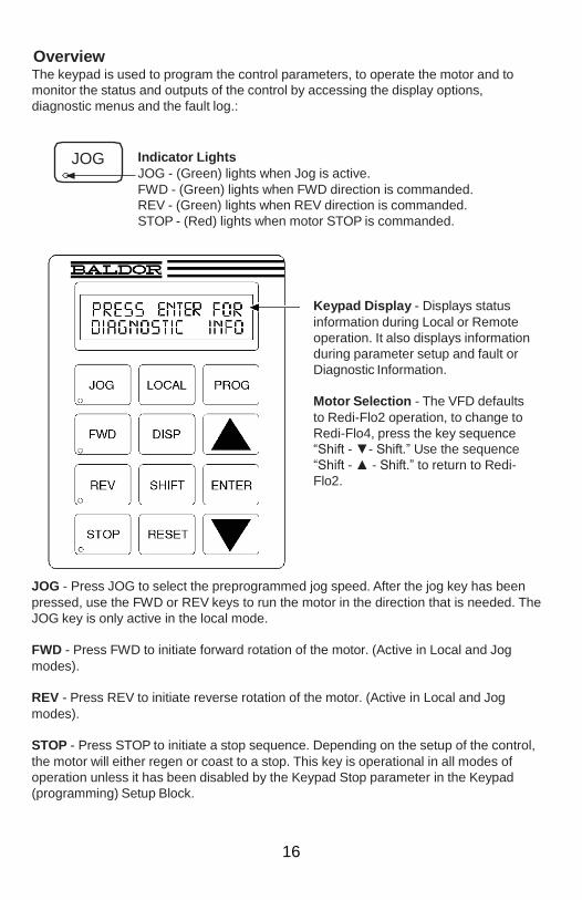
Overview The keypad is used to program the control parameters, to operate the motor and to
monitor the status and outputs of the control by accessing the display options,
diagnostic menus and the fault log.:
JOG
Indicator Lights
JOG - (Green) lights when Jog is active.
FWD - (Green) lights when FWD direction is commanded.
REV - (Green) lights when REV direction is commanded.
STOP - (Red) lights when motor STOP is commanded.
Keypad Display - Displays status
information during Local or Remote
operation. It also displays information
during parameter setup and fault or
Diagnostic Information.
Motor Selection - The VFD defaults
to Redi-Flo2 operation, to change to
Redi-Flo4, press the key sequence
“Shift - ▼- Shift.” Use the sequence
“Shift - ▲ - Shift.” to return to Redi-
Flo2.
JOG - Press JOG to select the preprogrammed jog speed. After the jog key has been
pressed, use the FWD or REV keys to run the motor in the direction that is needed. The
JOG key is only active in the local mode.
FWD - Press FWD to initiate forward rotation of the motor. (Active in Local and Jog
modes).
REV - Press REV to initiate reverse rotation of the motor. (Active in Local and Jog
modes).
STOP - Press STOP to initiate a stop sequence. Depending on the setup of the control,
the motor will either regen or coast to a stop. This key is operational in all modes of
operation unless it has been disabled by the Keypad Stop parameter in the Keypad
(programming) Setup Block.
17
LOCAL - Press LOCAL to change between the local (keypad) and remote operation.
DISP - Press DISP to return to display mode from programming mode. Provides
operational status and advances to the next display menu item.
SHIFT - Press SHIFT in the program mode to control cursor movement. Pressing the
SHIFT key once moves the blinking cursor one character position to the right. While in
program mode, a parameter value may be reset to the factory preset value by pressing
the SHIFT key until the arrow symbols at the far left of the keypad display are flashing,
then press an arrow key. In the display mode the SHIFT key is used to adjust the
keypad contrast.
RESET - Press RESET to clear all fault messages (in local mode). RESET can also be
used to return to the top of the block programming menu without saving any parameter
value changes.
PROG - Press PROG to enter the program mode. While in the program mode the
PROG key is used to edit a parameter setting.
▲ (UP Arrow) - Press ▲ to change the value of the parameter being displayed.
Pressing ▲ increments the value to the next greater value. Also, when the fault log or
parameter list is displayed, the ▲ key will scroll upward through the list. In the local
mode pressing the ▲ key will increase motor speed to the next greater value.
ENTER - Press ENTER to save parameter value changes and move back to the
previous level in the programming menu. In the display mode the ENTER key is used
to directly set the local speed reference. It is also used to select other operations when
prompted by the keypad display.
▼ (Down Arrow) - Press ▼ to change the value of the parameter being displayed.
Pressing ▼ decrements the value to the next lesser value. Also, when the fault log or
parameter list is displayed, the ▼ key will scroll downward through the list. In the local
mode pressing the ▼ key will decrease motor speed to the next lesser value.
18
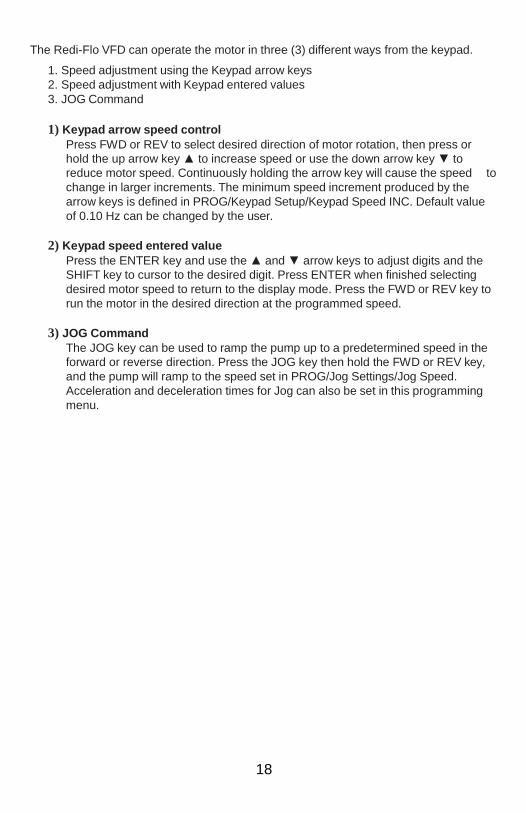
The Redi-Flo VFD can operate the motor in three (3) different ways from the keypad.
1. Speed adjustment using the Keypad arrow keys
2. Speed adjustment with Keypad entered values
3. JOG Command
1) Keypad arrow speed control
Press FWD or REV to select desired direction of motor rotation, then press or
hold the up arrow key ▲ to increase speed or use the down arrow key ▼ to
reduce motor speed. Continuously holding the arrow key will cause the speed to
change in larger increments. The minimum speed increment produced by the
arrow keys is defined in PROG/Keypad Setup/Keypad Speed INC. Default value
of 0.10 Hz can be changed by the user.
2) Keypad speed entered value
Press the ENTER key and use the ▲ and ▼ arrow keys to adjust digits and the
SHIFT key to cursor to the desired digit. Press ENTER when finished selecting
desired motor speed to return to the display mode. Press the FWD or REV key to
run the motor in the desired direction at the programmed speed.
3) JOG Command
The JOG key can be used to ramp the pump up to a predetermined speed in the
forward or reverse direction. Press the JOG key then hold the FWD or REV key,
and the pump will ramp to the speed set in PROG/Jog Settings/Jog Speed.
Acceleration and deceleration times for Jog can also be set in this programming
menu.

19
DISP Key
The DISP key can be used for accessing diagnostic and troubleshooting screens as
shown below:
20
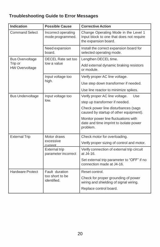
Troubleshooting Guide to Error Messages
Indication Possible Cause Corrective Action
Command Select Incorrect operating
mode programmed.
Change Operating Mode in the Level 1
Input block to one that does not require
the expansion board.
Need expansion
board.
Install the correct expansion board for
selected operating mode.
Bus Overvoltage
Trip or
HW Overvoltage
DECEL Rate set too
low a value
Lengthen DECEL time.
Add external dynamic braking resistors
or module.
Input voltage too
high.
Verify proper AC line voltage.
Use step down transformer if needed.
Use line reactor to minimize spikes.
Bus Undervoltage Input voltage too
low.
Verify proper AC line voltage. Use
step up transformer if needed.
Check power line disturbances (sags
caused by startup of other equipment).
Monitor power line fluctuations with
date and time imprint to isolate power
problem.
External Trip Motor draws
excessive
current
Check motor for overloading.
Verify proper sizing of control and motor.
External trip
parameter incorrect
Verify connection of external trip circuit
at J4-16.
Set external trip parameter to “OFF” if no
connection made at J4-16.
Hardware Protect Fault duration
too short to be
identified.
Reset control.
Check for proper grounding of power
wiring and shielding of signal wiring.
Replace control board.
21
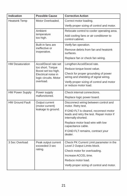
Indication Possible Cause Corrective Action
Heatsink Temp Motor Overloaded. Correct motor loading.
Verify proper sizing of control and motor.
Ambient
temperature
too high.
Relocate control to cooler operating area.
Add cooling fans or air conditioner to
control cabinet.
Built-in fans are
ineffective or
inoperative.
Verify fan operation.
Remove debris from fan and heatsink
surfaces.
Replace fan or check fan wiring.
HW Desaturation Accel/Decel rate set
too short. Torque
Boost set too high.
Electrical noise in
logic circuits. Motor
overload.
Lengthen Accel/Decel rate.
Reduce torque boost value.
Check for proper grounding of power
wiring and shielding of signal wiring.
Verify proper sizing of control and motor
or reduce motor load.
HW Power Supply Power supply
malfunctioned.
Check internal connections.
Replace logic power board.
HW Ground Fault Output current
(motor current)
leakage to ground.
Disconnect wiring between control and
motor. Retry test.
If GND FLT is cleared, reconnect motor
leads and retry the test. Repair motor if
internally shorted.
Replace motor lead wire with low
capacitance cable.
If GND FLT remains, contract your
dealer.
3 Sec Overload Peak output current
exceeded 3 sec
rating.
Check PK Current Limit parameter in the
Level 2 Output Limits block.
Check motor for overloading.
Increase ACCEL time.
Reduce motor load.
Verify proper sizing of control and motor.

22
Indication Possible Cause Corrective Action
1 Min Overload Peak output current
exceeded 1 minute
rating
Check PK Current Limit parameter in
Level 2 Output Limits block.
Check motor for overloading.
Increase ACCEL/DECEL times.
Reduce motor load.
Verify proper sizing of control and motor.
Unstable Speed Oscillating load.
Unstable input
power.
Slip compensation
too high.
Correct motor lead.
Correct input power.
Adjust slip compensation.

23
CAUTION!
Safety Issue Using the VFD Pump Controller
Potential Issue:
Three-phase motors controlled by Variable Frequency Drives
(VFD) inherently cause inductive feedback - often more than
4mA - thus tripping the 5mA ±1mA GFCI breaker on many
generators. Accordingly, if disabling the GFCI in a generator
you should follow manufacturer’s recommendations and
applicable safety and electrical codes.
Precautions:
If you are using a generator without a GFCI breaker, be
aware that this can pose additional serious safety hazards.
If you continue to use a generator without a GFCI breaker, IT
IS IMPERATIVE that you contact your safety personnel,
OSHA, and the National Electrical Code applicable and/or an
electrical engineer with experience in grounding issues before
installing your system! If using without a GFCI breaker, you
may need to implement an OSHA approved cord inspection
program.
For further details and employer responsibilities, refer to
https://www.osha.gov/doc/outreachtraining/htmlfiles/gfcicon.html.

24
Section 6: System Specifications
Pump Specifications
Input Power: 1.5 kW (2 Horsepower)
Voltage: 3 Phase, 220 volts at 400 Hz
Maximum Current: 5.5 amps
Motor Protection: Thermal overload - Thermik Geratebau,
Series SY6
Disconnect Temperature: 176 F (80 C)
Rate Current: 5 amps
Current Overload: incorporated into converter
Connections
Discharge port: 1/2” Female NPT
Operating Conditions
Maximum Fluid Temp: 86 F (30 C)
Minimum Fluid Temp: 34 F (1 C)
Dimensions and Weight
Dimensions: 11.3” (28.7 cm) x 1.81” (4.6 cm)
Net Weight: 5.5 lbs. (2.5 kg)
Reel System Specifications:
Dimensions and Weight
Dimensions: 23.2” W x 28.8” H x 27.7” D
(58.9cm x 73.2cm x 70.4cm)
Weight: 23 lbs.(10.4kg)
Capacity: 200 feet of PVC HAPPY HOSE!
(61 meters)
250 feet TLPE HAPPY HOSE!
(76.2 meters)
Connections
Discharge/Sample Port: 3/4” GHT
Available Lead Lengths 50, 100, 150, and 200 feet
(15.2, 30.5, 45.7, 61 meters)

25
HAPPY HOSE! Cable Specifications
PVC HAPPY HOSE!
HAPPY HOSE! I.D.: 1/2” (1.3cm)
HAPPY HOSE! O.D.: 3/4” (1.9cm)
Hose Materials: PVC clear, nylon reinforced
Cable Materials: Yellow, PVC jacketed
Cable O.D. 0.42” (1.1cm)
PTFE-lined Polyethylene HAPPY HOSE!
HAPPY HOSE! I.D.: 1/2” (1.3cm)
HAPPY HOSE! O.D.: 5/8” (1.6cm)
Hose Materials: Polyethylene, PTFE-lined
Cable Materials: Red, Polyethylene jacketed
Cable O.D.: 0.42” (1.1cm)
All HAPPY HOSE! Cable Specifications:
Cable Construction: includes: 4 each 16 EWG PVC jacketed,
color-coated conductors, and 1 each of
0.062” (0.15cm) dia., 7 x 7 stainless steel
wire rope - PVC or PE jacketed to 0.125”
(.32cm) dia.
Breaking Strength: 480 lbs. (218 kg)
Weight: 0.22 lbs per foot (0.33 kg per meter)

26
VFD Technical Specifications
DESCRIPTION RF2 RF4
Part I Rated Power & Markings
Input Voltage 1 X 115V +/- 10% or 1 X 230V +/- 10%
Single Phase Input
Output Voltage 3 X 220V 3 X 230V
Continuous Output Current (230V input) 6.05A 8.25A
Continuous Output Current (115V input) 6.05A 6.50A
Part II Fundamental Parameters
Control System PWM
Output Voltage Clamp @ 220V Clamp @ 230V
Carrier Freq. Selectable: 1-5 KHz
Freq. Resolution 0.1Hz*
Input Freq. Range 48 - 62 Hz
Maximum Output Frequency (230V input) 400 Hz 100 Hz
Maximum Output Frequency (115V input) 400 Hz 80 Hz
Base Frequency 400 Hz 100 Hz
Torque Boost 0-15% Nominal Voltage
V/F Pattern Selectable Linear/Square Law
Accel Time 0.5-3600 Seconds
Decel Time 0.5-3600 Seconds
Accel/Decel Pattern Linear
Part III Protective Functions
Ground Fault Ground Fault detection for Equipment
Protection
Overcurrent Output Short Circuit
Locked Rotor
Over Voltage 400VDC
Under Voltage 200VDC
Motor Overload 12 x T Characteristic
Line Start Lock Out VFD will not start upon input power
application
Line Transient Rating
860 VAV, 810J MOV Between any
power input terminal & Ground
360 VAC, 380 J MOV Between any two
power input terminals

27
DESCRIPTION RF2 RF4
Part IV Ambient Operating Conditions
Operating Temp. -10 to 40 degree C
Storage Temp. -30 to 65 degree C
Vibration 0.5G, Max / 57-150 Hz
Elevation 3300 ft. without de-rating
Max source fault current 5 Kamps
Enclosure rating UL Type 4, No Direct Sunlight

28
DOCUMENT REVISIONS
EDCF# DESCRIPTION REV/DATE Project #1432
Initial Release, SP 7/1/14

29
The Warranty For a period of one (1) year from date of first sale, product is warranted to be free from defects in materials and workmanship. Geotech agrees to repair or replace, at Geotech’s option, the portion proving defective, or at our option to refund the purchase price thereof. Geotech will have no warranty obligation if the product is subjected to abnormal operating conditions, accident, abuse, misuse, unauthorized modification, alteration, repair, or replacement of wear parts. User assumes all other risk, if any, including the risk of injury, loss, or damage, direct or consequential, arising out of the use, misuse, or inability to use this product. User agrees to use, maintain and install product in accordance with recommendations and instructions. User is responsible for transportation charges connected to the repair or replacement of product under this warranty.
Equipment Return Policy A Return Material Authorization number (RMA #) is required prior to return of any equipment to our facilities, please call our 800 number for appropriate location. A RMA # will be issued upon receipt of your request to return equipment, which should include reasons for the return. Your return shipment to us must have this RMA # clearly marked on the outside of the package. Proof of date of purchase is required for processing of all warranty requests. This policy applies to both equipment sales and repair orders.
FOR A RETURN MATERIAL AUTHORIZATION, PLEASE CALL OUR SERVICE DEPARTMENT AT 1-800-833-7958.
Model Number: ________________ Serial Number: ________________ Date of Purchase: ________________
Equipment Decontamination Prior to return, all equipment must be thoroughly cleaned and decontaminated. Please make note on RMA form, the use of equipment, contaminants equipment was exposed to, and decontamination solutions/methods used. Geotech reserves the right to refuse any equipment not properly decontaminated. Geotech may also choose to decontaminate the equipment for a fee, which will be applied to the repair order invoice.

Geotech Environmental Equipment, Inc. 2650 East 40th Avenue Denver, Colorado 80205
(303) 320-4764 ● (800) 833-7958 ● FAX (303) 322-7242 email: [email protected] website: www.geotechenv.com