Embed Size (px)
Citation preview

SMART-24 SERIES COMMAND & SETUP PROTOCOL
Interface Control Document
Version 2.1
MANUAL SUBJECT TO CHANGE WITHOUT NOTICE
March, 2012
GEOTECH INSTRUMENTS, LLC

Copyright 2003-2012 Geotech Instruments, LLC. All rights are reserved, including those to reproduce this manual or parts thereof in any form without permission in writing from Geotech Instruments, LLC.
This manual is protected by United States copyright law (Title 17 United States Code). Unauthorized reproduction and/or sales may result in imprisonment of up to one year
and fines of up to $10,000 (17 USC 506). Copyright infringers may be subject to civil liability.
For information relating to other Geotech Instruments products and manuals, inquires may be addressed to:
GEOTECH INSTRUMENTS, LLC10755 Sanden Drive, Dallas, Texas 75238-1336
Phone: 214 221-0000 Fax: 214 343-4400Web: www.geoinstr.com

SMART-24 Series Command & Setup Protocol ICD
i
Revision History
Date By Change Description
September 12, 2003
P. Akers Version 1.0 initial release.
March 10, 2004 P. Akers Version 1.1 release.
Changes:
• Modified prompts in section 3.3.
• Added support for up to 5 serial ports [port] in the serial port related commands (3.6.1.2).
• Changed [mode] values for SPM command (3.6.1.2.2).
• Changed [protocol] values for SPP command (3.6.1.2.3).
• Added new SPC command (3.6.1.2.4).
• Renamed the following commands:
o EIA to IPA (3.6.1.3.1)
o EIM to IPM (3.6.1.3.2)
o EIG to IPG (3.6.1.3.3)
o EIH to IPH (3.6.1.3.4)
o EID to IPD (3.6.1.3.5)
o EIN to IPN (3.6.1.3.6)
o ECM to IDM (3.6.1.3.7)
• Added support for up to 7 TCP/IP ports [port] in the TCP/IP related commands (3.6.1.3).
• Removed the [port] parameter from the IPH command (3.6.1.3.4). The Smart24 only uses one global host name for all TCP/IP connections.
• Added IPE command (3.6.1.3.8)
• Added ISA command (3.6.1.3.9)
• Added ISM command (3.6.1.3.10)
• Added ICA command (3.6.1.3.11)
• Renamed commands ECE to CCE and ECD to CCD, then moved them to the CD 1.1 related command section (3.6.1.4) at sections 3.6.1.4.13 and 3.6.1.4.14 respectively.
• Added the CD 1.1 profile parameter [profile] to each CD 1.1 related command in section 3.6.1.4.
• Removed the internal IP port [port] parameter from the CDA (3.6.1.4.11) and CCP (3.6.1.4.12) commands.
• Added CDE command (3.6.1.4.15).

SMART-24 Series Command & Setup Protocol ICD
ii
• Added CRT command (3.6.1.4.16).
• Added CIP command (3.6.1.4.17).
• Added CRR command (3.6.1.4.18).
• Added USR command (3.6.4.2.3).
• Added SUN command (3.6.4.2.4).
• Added SCP command (3.6.4.2.5).
• Added SCU command (3.6.4.2.6).
• Get State of Health (3.6.4.5.2) changed DSP_FLASH to DSP_+3.3V, DSP_PSEUDO to DSP_GND and DSP_SDRAM to DSP_+5V.
• Added section 3.6.4.6, LOG System Commands.
• Added LGE command (3.6.4.6.1).
• Added LGD command (3.6.4.6.2).
• Added LGT command (3.6.4.6.3).
April 1, 2004 P. Akers Version 1.2 release.
Changes:
• Changed channel gain values in section 3.6.1.1.5.
• Changed data mode values in section 3.6.1.2.2.
• Changed protocol values in section 3.6.1.2.3.
• Changed character mode values in section 3.6.1.2.4.
• Changed data type values to numerical values in section 3.6.1.4.4.
• Added mode parameter to all calibration commands in section 3.6.2.1.
• Added GPS Slave mode to TSM command (3.6.3.1.1).
• Changed channel parameter of the OSC command (3.6.4.3.1) to board number.
• Added HLP command (3.6.4.1.8).
• Added LGO command (3.6.4.1.9).
• Added SFD command (3.6.4.1.10).
• Moved SCG command from Table 4 to Table 3.
• Removed the port parameter from the IPS command (3.6.4.5.4).
June 1, 2004 P. Akers Version 1.3 release.
Changes:
SMART-24 Series Command & Setup Protocol ICD
iii
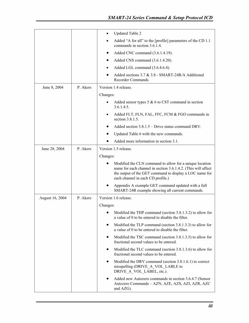
• Updated Table 2
• Added “A for all” to the [profile] parameters of the CD 1.1 commands in section 3.6.1.4.
• Added CNC command (3.6.1.4.19). • Added CNS command (3.6.1.4.20). • Added LGL command (3.6.4.6.4).
• Added sections 3.7 & 3.8 - SMART-24R/A Additional Recorder Commands
June 8, 2004 P. Akers Version 1.4 release.
Changes:
• Added sensor types 5 & 6 to CST command in section 3.6.1.4.5.
• Added FLT, FLN, FAL, FFC, FCM & FGO commands in section 3.8.1.5.
• Added section 3.8.1.5 – Drive status command DRV. • Updated Table 6 with the new commands. • Added more information in section 3.1.
June 28, 2004 P. Akers Version 1.5 release.
Changes:
• Modified the CLN command to allow for a unique location name for each channel in section 3.6.1.4.2. (This will affect the output of the GET command to display a LOC name for each channel in each CD profile.)
• Appendix A example GET command updated with a full SMART-24R example showing all current commands.
August 16, 2004 P. Akers Version 1.6 release.
Changes:
• Modified the THP command (section 3.8.1.3.2) to allow for a value of 0 to be entered to disable the filter.
• Modified the TLP command (section 3.8.1.3.3) to allow for a value of 0 to be entered to disable the filter.
• Modified the TSC command (section 3.8.1.3.5) to allow for fractional second values to be entered.
• Modified the TLC command (section 3.8.1.3.6) to allow for fractional second values to be entered.
• Modified the DRV command (section 3.8.1.6.1) to correct misspelling (DRIVE_A_VOL_LABLE to DRIVE_A_VOL_LABEL, etc.).
• Added new Autozero commands in section 3.6.4.7 (Sensor Autozero Commands – AZN, AZE, AZS, AZI, AZR, AZC and AZG).

SMART-24 Series Command & Setup Protocol ICD
iv
• Added new calibration signal types to the CAO command (section 3.6.2.1.1).
• Modified the digital calibration control modes of the CAC command (section 3.6.2.1.7).
• Modified the continuous recording modes of the CRM command (section 3.8.1.1.1) to support a ring buffer mode and a fill all mode only.
• Added new SOH recording commands in section 3.8.1.7 (STD & SGO) for future reference.
• Added new LOG recording commands in section 3.8.1.8 (LTD & FGG).
• Updated tables to reflect new commands. October 26, 2004 P. Akers Version 1.7 release.
Changes:
• Updated the secondary sample rate command SRS (section 3.6.1.1.2) to show the available secondary sample rates.
• Updated LOG System Commands (section 3.6.4.6) with a note on usage.
• Updated LGE command (section 3.6.4.6.1) to add all LOG message types available.
• Updated LGD command (section 3.6.4.6.2) to add all LOG message types available.
• Updated LGL command (section 3.6.4.6.4) to give the meaning of each debug log level. LGL is now saved in FLASH setup and returned in the GET response.
• Added section 3.8.1.9 Miscellaneous Commands. • Added new command, USB Hardware Enable/Disable
(section 3.8.1.9.1). • Updated Table 7 with new USB command and notes.
December 23, 2004 P. Akers Version 1.8 release.
Changes:
• Updated allowed values and factory defaults to all relevant commands.
• Added new command, SFG, Set Front-End Gain Value (section 3.6.1.1.6).
• Added new command, SSS, Set Sensor Sensitivity Value (section 3.6.1.1.7).
• Added new command, ANO, Anonymous FTP Access Enable/Disable (section 3.6.1.3.12).
• Added new command, DMF, Set Data Move Percent Full Trigger Limit (section 3.8.1.9.2).
• Added new command, DMI, Start Data File Move

SMART-24 Series Command & Setup Protocol ICD
v
Immediately Command (section 3.8.1.9.3). • Added new command, DMT, Set Data Move Time Interval
Trigger Limit (section 3.8.1.9.4). • Added new command, NPD, No Power Down Drive Mode
Enable/Disable (section 3.8.1.9.5). December 05, 2005 P. Akers Version 1.9 release.
Changes:
• Added new command, SFT, Set ADC FIR Filter Type (section 3.6.1.1.8).
• Added new command, SSD, Enable/Disable ADC Time Sync Delay Correction (section 3.6.1.1.9).
• Added new command, URT, Set USGS RTD Format (section 3.6.1.2.5).
• Added new command, CDS, Set CD 1.1 Data Frame Save Size (section 3.6.1.4.21).
• Added new command, CSS, Set CD 1.1 SOH Frame Save Size (section 3.6.1.4.22).
• Added new command, DDC, Set LCD Data Display Control (section 3.6.4.1.11).
• Added new command, GCS, Get Data Channel Statistics (section 3.6.4.5.6).
• Added new command, GPC, Set GPS Configuration (section 3.6.3.2.2).
• Added new command, GPT, Get GPS Satellite Tracking Status (section 3.6.4.5.7).
• Updated the LGL command, Set LOG Debug Message Level (section 3.6.4.6.4).
• Added new command, CBF, Enable/Disable CD Backfill Mode (section 3.6.1.4.23).
• Added new command, AGK, Generate New DSA Key Pair (section 3.6.4.8.1).
• Added new command, ARK, Start/Abort A Pending DSA Key Pair (section 3.6.4.8.2).
• Added new command, ASK, Start/Abort A Pending DSA Key Pair (section 3.6.4.8.3).
• Added new command, AUG, Set User DSA G Values (section 3.6.4.8.4).
• Added new command, AUP, Set User DSA P Values (section 3.6.4.8.5).
• Added new command, AUQ, Set User DSA Q Values (section 3.6.4.8.6).
• Added new command, PCS, Get PCMCIA PC Card Status

SMART-24 Series Command & Setup Protocol ICD
vi
(section 3.6.4.5.8).
• Added new command, FZS, Get Fortezza Card Status (section 3.6.4.5.9).
August 26, 2010 Version 2.0 release.
Changes:
• Added new command, RST, Hardware Reset (section 3.6.4.1.7).
• Added new command, GTS, Get Time Synchronization Status (section 3.6.4.5.10).
• Added new command, AZW, Set Autozero Pulse Width (section 3.6.4.7.8).
• Added new command, OSR, Set Offset to Remove from AUX & Mass Position Channels (section 3.6.4.3.2).
• Added new command, DRT, Display IP Routing Table Status (section 3.6.4.5.11).
• Added new command, IPP, Set Primary IP Port (section 3.6.1.3.13).
• Added new command, SPH, Set PPP Connection Handshake Mode (section 3.6.1.3.14).
• Updated commands CTD (section 3.8.1.1.3), ETD (section 3.8.1.2.2), LTD (section 3.8.1.8.1) and STD (section 3.8.1.7.1) to add support for USB Drive Extended Partition.
• Added new command, CTM, Enable/Disable CD Send Triggered Data (section 3.6.1.4.25).
• Added new commands, EWE, Enable/Disable Earthworm Profile (section 3.6.1.5.1), EWI, Set Earthworm Installation ID (section 3.6.1.5.2) and EWM, Set Earthworm Module ID (section 3.6.1.5.3).
• Added new command, GOS, Set GPS Local Time Offset (section 3.6.3.2.3).
• Added new command, CBM, Set CD Backfill Mode (section 3.6.1.4.24).
March, 2012 Version 2.1 release.
Changes:
• Added new command, EWS, Set Earthworm Client/Server Mode (section 3.6.1.5.4).
SMART-24 Series Command & Setup Protocol ICD
vii
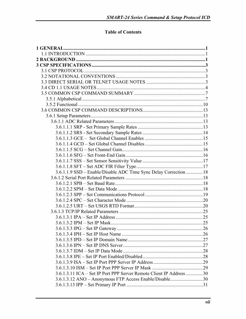
Table of Contents 1 GENERAL.....................................................................................................................1
1.1 INTRODUCTION ...................................................................................................1 2 BACKGROUND ...........................................................................................................1 3 CSP SPECIFICATIONS..............................................................................................3
3.1 CSP PROTOCOL ....................................................................................................3 3.2 NOTATIONAL CONVENTIONS ..........................................................................3 3.3 DIRECT SERIAL OR TELNET USAGE NOTES .................................................3 3.4 CD 1.1 USAGE NOTES..........................................................................................4 3.5 COMMON CSP COMMAND SUMMARY ...........................................................7
3.5.1 Alphabetical ......................................................................................................7 3.5.2 Functional .......................................................................................................10
3.6 COMMON CSP COMMAND DESCRIPTIONS..................................................13 3.6.1 Setup Parameters.............................................................................................13
3.6.1.1 ADC Related Parameters .........................................................................13 3.6.1.1.1 SRP - Set Primary Sample Rates ......................................................13 3.6.1.1.2 SRS - Set Secondary Sample Rates ..................................................14 3.6.1.1.3 GCE – Set Global Channel Enables ................................................15 3.6.1.1.4 GCD – Set Global Channel Disables ................................................15 3.6.1.1.5 SCG – Set Channel Gain...................................................................16 3.6.1.1.6 SFG – Set Front-End Gain................................................................16 3.6.1.1.7 SSS – Set Sensor Sensitivity Value ..................................................17 3.6.1.1.8 SFT – Set ADC FIR Filter Type .......................................................17 3.6.1.1.9 SSD – Enable/Disable ADC Time Sync Delay Correction ..............18
3.6.1.2 Serial Port Related Parameters ................................................................18 3.6.1.2.1 SPB – Set Baud Rate.........................................................................18 3.6.1.2.2 SPM – Set Data Mode ......................................................................18 3.6.1.2.3 SPP – Set Communications Protocol................................................19 3.6.1.2.4 SPC – Set Character Mode ...............................................................20 3.6.1.2.5 URT – Set USGS RTD Format.........................................................20
3.6.1.3 TCP/IP Related Parameters .....................................................................25 3.6.1.3.1 IPA – Set IP Address ........................................................................25 3.6.1.3.2 IPM – Set IP Mask............................................................................25 3.6.1.3.3 IPG – Set IP Gateway .......................................................................26 3.6.1.3.4 IPH – Set IP Host Name ...................................................................26 3.6.1.3.5 IPD – Set IP Domain Name ..............................................................27 3.6.1.3.6 IPN – Set IP DNS Server ..................................................................27 3.6.1.3.7 IDM – Set IP Data Mode ..................................................................28 3.6.1.3.8 IPE – Set IP Port Enabled/Disabled..................................................28 3.6.1.3.9 ISA – Set IP Port PPP Server IP Address .........................................29 3.6.1.3.10 ISM – Set IP Port PPP Server IP Mask ..........................................29 3.6.1.3.11 ICA – Set IP Port PPP Server Remote Client IP Address ..............30 3.6.1.3.12 ANO – Anonymous FTP Access Enable/Disable...........................30 3.6.1.3.13 IPP – Set Primary IP Port ...............................................................31
SMART-24 Series Command & Setup Protocol ICD
viii
3.6.1.3.14 SPH – Set PPP Connection Handshake Mode................................31 3.6.1.4 CD 1.1 Related Parameters ......................................................................32
3.6.1.4.1 CSN - Set CD Site Name ..................................................................32 3.6.1.4.2 CLN - Set CD Location Name..........................................................32 3.6.1.4.3 CCN - Set CD Channel Name ..........................................................33 3.6.1.4.4 CDT - Set CD Data Type..................................................................33 3.6.1.4.5 CST - Set CD Sensor Type ...............................................................34 3.6.1.4.6 CCM - Set CD Compression.............................................................35 3.6.1.4.7 CAM - Set CD Authentication..........................................................35 3.6.1.4.8 CCL - Set CD Calib/Calper ..............................................................36 3.6.1.4.9 CDF - Set CD Data Frame Size ........................................................36 3.6.1.4.10 CSF - Set CD SOH Alert Frequency ..............................................37 3.6.1.4.11 CDA - Set CD Destination IP Address ...........................................37 3.6.1.4.12 CCP - Set CD Connection Request Remote Port............................38 3.6.1.4.13 CCE – Set Data Channel Enables ...................................................38 3.6.1.4.14 CCD – Set Data Channel Disables .................................................39 3.6.1.4.15 CDE – Enable/Disable CD Profile..................................................39 3.6.1.4.16 CRT – Set CD Connection Request Timeout .................................40 3.6.1.4.17 CIP – Set CD Command Input Port ................................................40 3.6.1.4.18 CRR – Set CD Connection Request Retry......................................41 3.6.1.4.19 CNC – Set CD Creator Name .........................................................41 3.6.1.4.20 CNS – Set CD Station Name ..........................................................42 3.6.1.4.21 CDS – Set CD Data Frame Save Size.............................................42 3.6.1.4.22 CSS – Set CD SOH Frame Save Size.............................................43 3.6.1.4.23 CBF – Enable/Disable CD Backfill Mode......................................43 3.6.1.4.24 CBM – Set CD Backfill Mode........................................................44 3.6.1.4.25 CTM – Enable/Disable CD Send Triggered Data ..........................44
3.6.1.5 Earthworm Related Parameters................................................................45 3.6.1.5.1 EWE – Enable/Disable Earthworm Profile.......................................45 3.6.1.5.2 EWI – Set Earthworm Installation ID...............................................45 3.6.1.5.3 EWM – Set Earthworm Module ID ..................................................46 3.6.1.5.4 EWS – Set Earthworm Client/Server Mode .....................................46
3.6.2 Calibration Parameters....................................................................................47 3.6.2.1 Calibration Related Parameters ...............................................................47
3.6.2.1.1 CAO – Set Calibration Output Signal...............................................47 3.6.2.1.2 CAA – Set Calibration Amplitude....................................................47 3.6.2.1.3 CAF – Set Calibration Frequency.....................................................48 3.6.2.1.4 CAW – Set Calibration Pulse or Bit Width ......................................48 3.6.2.1.5 CAD – Set Calibration Duration.......................................................49 3.6.2.1.6 CAS – Set Calibration Relay State ...................................................49 3.6.2.1.7 CAC – Set Calibration Digital Control Enable.................................50 3.6.2.1.8 CAI – Set Calibration Interval ..........................................................50 3.6.2.1.9 CAR – Set Calibration Repetitions...................................................51 3.6.2.1.10 CAT – Set Calibration Start Time ..................................................51
3.6.3 Time and Synchronization Parameters ...........................................................52 3.6.3.1 Synchronization Related Commands.......................................................52

SMART-24 Series Command & Setup Protocol ICD
ix
3.6.3.1.1 TSM – Set Time Synchronization Mode ..........................................52 3.6.3.1.2 JST – Set Jamset Threshold ..............................................................52
3.6.3.2 GPS Related Commands..........................................................................53 3.6.3.2.1 GCT – Set GPS Cycle Time .............................................................53 3.6.3.2.2 GPC – Set GPS Configuration..........................................................53 3.6.3.2.3 GOS – Set GPS Local Time Offset...................................................54
3.6.3.3 Time Related Commands.........................................................................55 3.6.3.3.1 SET – Set Time.................................................................................55
3.6.4 Commands ......................................................................................................55 3.6.4.1 Setup and Boot Commands......................................................................55
3.6.4.1.1 ABT – Abort Setup ...........................................................................55 3.6.4.1.2 ASR – Accept Setup and Reboot ......................................................55 3.6.4.1.3 BTL – Boot into the Boot Loader .....................................................55 3.6.4.1.4 GET – Get Setup...............................................................................56 3.6.4.1.5 OFF – Power Off ..............................................................................56 3.6.4.1.6 RBT – Reboot ...................................................................................56 3.6.4.1.7 RST – Generate a Harware Reset .....................................................56 3.6.4.1.8 HLP – Help .......................................................................................56 3.6.4.1.9 LGO – Logout...................................................................................57 3.6.4.1.10 SFD – Set Factory Defaults ............................................................57 3.6.4.1.11 DDC – Set LCD Data Display Control...........................................57
3.6.4.2 Password Commands ...............................................................................57 3.6.4.2.1 PSW – Enter System Password.........................................................58 3.6.4.2.2 SPW – Set System Password ............................................................58 3.6.4.2.3 USR – Enter System Username ........................................................58 3.6.4.2.4 SUN – Set System Username ...........................................................59 3.6.4.2.5 SCP – Set Client Password ...............................................................59 3.6.4.2.6 SCU – Set Client Username..............................................................59
3.6.4.3 ADC Commands ......................................................................................60 3.6.4.3.1 OSC – Start ADC Offset Calibration................................................60 3.6.4.3.2 OSR – Set Offset Value to Remove from AUX & Mass Position Channels...........................................................................................................60 3.6.4.3.3 RCL – ADC Relay Control...............................................................60
3.6.4.4 Calibration Commands ............................................................................61 3.6.4.4.1 CAG – Calibration Go ......................................................................61 3.6.4.4.2 CAH – Calibration Halt ....................................................................61
3.6.4.5 Status Commands.....................................................................................62 3.6.4.5.1 TYP – Get Smart-24 Type ................................................................62 3.6.4.5.2 SOH – Get State of Health................................................................62 3.6.4.5.3 GPS– Get GPS Status .......................................................................64 3.6.4.5.4 IPS– Get IP Status.............................................................................65 3.6.4.5.5 HWS– Get Hardware Status .............................................................66 3.6.4.5.6 GCS - Get DATA Channel Statistics................................................68 3.6.4.5.7 GPT - Get GPS Satellite Tracking Status .........................................69 3.6.4.5.8 PCS – Get PCMCIA PC Card Status................................................70 3.6.4.5.9 FZS – Get Fortezza Card Status .......................................................71

SMART-24 Series Command & Setup Protocol ICD
x
3.6.4.5.10 GTS – Get Time Synchronization Status........................................73 3.6.4.5.11 DRT – Display the IP Routing Table Status...................................73
3.6.4.6 LOG System Commands .........................................................................74 3.6.4.6.1 LGE – Enable Specific LOG Messages............................................74 3.6.4.6.2 LGD – Disable Specific LOG Messages ..........................................76 3.6.4.6.3 LGT – Enable/Disable Long Time in LOG Messages......................77 3.6.4.6.4 LGL – Set LOG Debug Message Level Enable/Disable ..................77
3.6.4.7 Sensor Autozero Commands....................................................................78 3.6.4.7.1 AZN – Immediate Autozero Command............................................78 3.6.4.7.2 AZE – Set Scheduled Autozero Enable/Disable...............................79 3.6.4.7.3 AZS – Set Scheduled Autozero Start Time ......................................79 3.6.4.7.4 AZI – Set Scheduled Autozero Interval............................................80 3.6.4.7.5 AZR – Set Scheduled Autozero Repetitions.....................................80 3.6.4.7.6 AZC – Set Scheduled Autozero Channels ........................................81 3.6.4.7.7 AZG – Save & Start Using New Scheduled Autozero Parameters ..81 3.6.4.7.8 AZW – Autozero Pulse Width..........................................................82
3.6.4.8 Fortezza (Authentication) Card Commands ............................................82 3.6.4.8.1 AGK – Generate New DSA Key Pair...............................................82 3.6.4.8.2 ARK – Return DSA Public Key .......................................................83 3.6.4.8.3 ASK – Start/Abort A Pending DSA Key Pair ..................................85 3.6.4.8.4 AUG – Set User DSA G Values .......................................................85 3.6.4.8.5 AUP – Set User DSA P Values.........................................................86 3.6.4.8.6 AUQ – Set User DSA Q Values .......................................................87 3.6.4.8.7 Notes On Fortezza Card and Key Management Usage ....................88
3.7 ADDITIONAL RECORDER CSP COMMAND SUMMARY ............................90 3.7.1 Alphabetical ....................................................................................................90
3.8 ADDITIONAL RECORDER CSP COMMAND DESCRIPTIONS.....................92 3.8.1 SMART-24R & SMART-24A Additional Recorder Commands...................92
3.8.1.1 Continuous Recording Commands ..........................................................92 3.8.1.1.1 CSM – Set Continuous Start Mode...................................................92 3.8.1.1.2 CRM – Set Continuous Recording Mode .........................................92 3.8.1.1.3 CTD – Set Continuous Target Drive ................................................93 3.8.1.1.4 CFS – Set Continuous File Size........................................................93 3.8.1.1.5 CTI – Set Continuous Start Time .....................................................94 3.8.1.1.6 CDB – Set Continuous Drive Buffer Size ........................................94 3.8.1.1.7 CCR – Set Continuous Channels to Record .....................................95 3.8.1.1.8 CGO – Save & Start Using New Continuous Recording Parameters95
3.8.1.2 Event Recording Commands ...................................................................96 3.8.1.2.1 ESM – Set Event Start Mode............................................................96 3.8.1.2.2 ETD – Set Event Target Drive..........................................................96 3.8.1.2.3 EPR – Set Pre-Event Record Time ...................................................97 3.8.1.2.4 EPO – Set Post-Event Record Time .................................................97 3.8.1.2.5 EMA – Set Max-Event Record Time................................................98 3.8.1.2.6 ETW – Set Event Trigger Window...................................................98 3.8.1.2.7 ETV – Set Event Trigger Vote Level ...............................................98 3.8.1.2.8 EST – Set Event Record Start Time .................................................99

SMART-24 Series Command & Setup Protocol ICD
xi
3.8.1.2.9 ECV – Set Channel Vote Weight......................................................99 3.8.1.2.10 ECR – Set Event Channels to Record...........................................100 3.8.1.2.11 EGO – Save & Start Using New Event Recording Parameters ....100
3.8.1.3 Trigger Setup Commands ......................................................................100 3.8.1.3.1 TMO – Set Trigger Mode ...............................................................101 3.8.1.3.2 THP – Set Trigger High Pass Corner Frequency............................101 3.8.1.3.3 TLP – Set Trigger Low Pass Corner Frequency.............................102 3.8.1.3.4 TLV – Set Level Trigger Threshold ...............................................102 3.8.1.3.5 TSC – Set STA Time Constant.......................................................103 3.8.1.3.6 TLC – Set LTA Time Constant ......................................................103 3.8.1.3.7 TTR – Set STA/LTA Trigger Ratio................................................103 3.8.1.3.8 TDR – Set STA/LTA De-Trigger Ratio .........................................104 3.8.1.3.9 TUL – Set Updating LTA Enable/Disable .....................................104 3.8.1.3.10 TGO – Save & Start Using New Trigger Setup Parameters.........105
3.8.1.4 Window Recording Commands .............................................................105 3.8.1.4.1 WEN – Set Recording Window Enable/Disable ............................105 3.8.1.4.2 WMO – Set Recording Window Mode ..........................................106 3.8.1.4.3 WST – Set Recording Window Start Time.....................................106 3.8.1.4.4 WDU – Set Recording Window Duration ......................................106 3.8.1.4.5 WIN – Set Recording Window Interval..........................................107 3.8.1.4.6 WRE – Set Recording Window Repetitions...................................107 3.8.1.4.7 WGO – Save & Start Using New Window Recording Parameters 108
3.8.1.5 File Recording Commands ....................................................................108 3.8.1.5.1 FFM – Set File Format....................................................................108 3.8.1.5.2 FCP – Set File Compression Mode.................................................109 3.8.1.5.3 FLT - Set Fixed Latitude ................................................................109 3.8.1.5.4 FLN - Set Fixed Longitude .............................................................110 3.8.1.5.5 FAL - Set Fixed Altitude ................................................................110 3.8.1.5.6 FFC – Force Fixed Coordinates to GPS Coordinates .....................110 3.8.1.5.7 FCM – File Coordinate Mode.........................................................111 3.8.1.5.8 FGO – Save & Start Using New File Recording Parameters .........111
3.8.1.6 Drive Status Commands ........................................................................111 3.8.1.6.1 DRV – Get Drive Status .................................................................111
3.8.1.7 SOH Recording Commands...................................................................113 3.8.1.7.1 STD – Set SOH Target Drive .........................................................113 3.8.1.7.2 SGO – Save & Start Using New SOH Recording Parameters........114
3.8.1.8 LOG Recording Commands ..................................................................114 3.8.1.8.1 LTD – Set LOG Target Drive.........................................................114 3.8.1.8.2 LGG – Save & Start Using New LOG Recording Parameters .......115
3.8.1.9 Miscellaneous Commands ....................................................................115 3.8.1.9.1 USB –Enable/Disable the Host USB Hardware Interface ..............115 3.8.1.9.2 DMF – Set Data Move Percent Full Trigger Limit ........................115 3.8.1.9.3 DMI – Start Data Move Immediately .............................................116 3.8.1.9.4 DMT – Set Data Move Time Interval Trigger Limit......................116 3.8.1.9.5 NPD – No Power Down Drive Enable/Disable ..............................117
A. APPENDIX A – Example GET output .................................................................118

SMART-24 Series Command & Setup Protocol ICD
xii
List of Tables Table 1. SMART Series Available CD 1.1 Data Channels...........................................6 Table 2. Alphabetical Common CSP Command Summary.........................................7 Table 3. Common CSP Command Functions..............................................................10 Table 4. Common CSP Setup Functions......................................................................11 Table 5. Common CSP Calibration Functions............................................................12 Table 6. Common CSP Autozero Functions................................................................13 Table 7. USGS RTD Output Data Format ..................................................................22 Table 8. Alphabetical Recorder CSP Command Summary ......................................90
SMART-24 Series Command & Setup Protocol ICD
1
SMART Series Command & Setup Protocol ICD
1 GENERAL 1.1 INTRODUCTION This interface control document (ICD) defines the ASCII Command and Setup Protocol (CSP) used to provide the user command and setup interface to Geotech’s SMART Series instruments. It covers the communication protocol and the format of messages that flow between a SMART Series instrument and a host computer. 2 BACKGROUND The SMART Series of instruments include a wide range of seismic data acquisition products. The set of electronic cards that make up the SMART Series can be combined to form remote digitizers, loggers and strong motion recorders. Commands can be sent to and responses received from a SMART Series instrument to configure, control and monitor its operation. This is the user interface. Data and State of Health information from a SMART Series instrument is generally collected either as a real time data stream or off-line as data files. This is the data interface. The CSP user interface described in this document is a simple human readable ASCII protocol. This interface can be accessed in one of three ways:
• Directly via a serial port running in a terminal mode and using a program such as HyperTerminal on a PC to manually enter commands and receive responses and status.
• Telnet over a TCP/IP connection (serial PPP and ethernet) to a host computer to
manually enter commands and receive responses and status.
• Wrapped in CD 1.1 protocol command and response frames. The data interface uses the CD 1.1 protocol data and alert frames to transmit data and state of health information in real time to a host computer. Please refer to the CD 1.1 documentation for details on this format and protocol specification. Data can also be retrieved off line from some SMART Series instruments as CD1.1 formatted data files. Please refer to the SMART-24 User’s Manual for specifics of this file format.

SMART-24 Series Command & Setup Protocol ICD
2
This page intentionally left blank.
SMART-24 Series Command & Setup Protocol ICD
3
3 CSP SPECIFICATIONS 3.1 CSP PROTOCOL The SMART Series CSP protocol is a simple clear ASCII command and response format. It uses three letter commands with optional parameters to command and control a SMART Series instrument. Some commands execute immediately, while others require a system reboot. In any case, after all parameters have been set as desired, the ASR command should be issued the save the parameters into FLASH. This command will decide whether a system reboot is required or not. The following are the factory default username and password to access the CSP, Telnet and FTP: Factory default username: smart24 Factory default password: changeme The following sections describe the CSP protocol in detail. 3.2 NOTATIONAL CONVENTIONS The following notational conventions are used in the specification:
_ - The underscore represents required spaces. , - Commas are required where shown. <ENTER> - Enter key on the PC or a Carriage Return (CR) byte 0x0d <CR> - Carriage Return (CR) byte 0x0d <LF> - Line Feed (LF) byte 0x0a 3.3 DIRECT SERIAL OR TELNET USAGE NOTES The SMART Series CSP protocol can be used directly via a serial port running in a terminal mode. Using a program such as HyperTerminal on a PC, the user can manually enter commands and receive responses and status from a SMART Series instrument. In a networked environment, Telnet can also be used to directly access the CSP interface over a TCP/IP connection (serial PPP and ethernet). When using a direct connection, prompts are used to indicate commands and responses as follows: > Waiting for a command input from the user. A response may be; OK indicating success, ERROR indicating an error occurred or the requested information.

SMART-24 Series Command & Setup Protocol ICD
4
The following is an example of a successful command: > IPA_1P,192.168.0.1<ENTER> OK<CR><LF> > [Waiting for next command] The following is an example of a command error: > IPA_1P,1920.168.0.1<ENTER> Invalid Parameters!<CR><LF> > [Waiting for next command] The following is an example of a command query: > IPA_1P,?<ENTER> IPA_1P,192.168.0.1<CR><LF> > [Waiting for next command] The following is an example of getting command help: > IPA_/?<ENTER> IPA [port],[IP address]<CR> [port] - 1E,2E,1S,2S,3S,4S,5S [IP address] - IP address, XXX.XXX.XXX.XXX > [Waiting for next command] The following is an example of a status command: > SOH<ENTER> SOH START<CR><LF>
TIME: 21:58:35,06/04/2004 [other SOH] SOH END<CR><LF> > [Waiting for next command] If a username and password have been set to control access to the instrument, the username and password must be given using the USR and PSW commands before any other commands will be processed. 3.4 CD 1.1 USAGE NOTES The CSP protocol can be used wrapped in CD 1.1 command request and response frames. Commands are embedded in the command message field of the CD 1.1 command request frame. Single commands may be sent (one per command request frame) as well as multiple commands in one frame. Command response frames will report back OK if all commands were processed without error, ERROR if an error occurred or with any

SMART-24 Series Command & Setup Protocol ICD
5
requested status information. The prompts shown in section 3.3 are not used when the CSP is wrapped inside CD 1.1 frames. If the username and password has been set to control access to the instrument, they must be given using the USR & PSW commands before any other commands will be processed. If the TCP/IP connection is lost or dropped, the password must be given again to gain access. Other CD 1.1 usage notes:
• Start most command requests (except queries below) with: "USR smart24\r\n" "PSW changeme\r\n"
where "smart24" and "changeme" are the current username and password to ensure access. The username/password access times out after 10 minutes on no activity.
• The following commands should always be used alone (USR & PSW before them
are OK) as they return a large amount of data:
GET HLP HWS IPS GPS SOH
• Queries can only be used when issued as a single command (not even USR &
PSW can be used in the same frame). Example:
"SPB 1,?\r\n" returns: "SPB 1,115200\r\n"
• When multiple commands are issued in one frame, the following will be returned
when all were processed OK (if there where 105 commands in the request frame): "COMMAND_MULTIPLE_COMMANDS_PROCESSED_OK 105\r\n"
• Note if any one command in a multiple command request fails, processing is stopped and any commands already processed are aborted if possible.
• Possible error messages that could be returned:

SMART-24 Series Command & Setup Protocol ICD
6
"COMMAND_MEMORY_ALLOCATION_ERROR\r\n" - Internal memory allocation error. (BAD!) "COMMAND_FORMAT_ERROR\r\n" - Command was understood but parameters where bad, if you issue a USR or PSW with the wrong username or password you will get this message. "COMMAND_INVALID_ERROR\r\n" - Did not recognize a command at all. Not in my lookup list. "COMMAND_ACCESS_DENIED_ERROR\r\n" - Command was issued with giving the correct USR & PSW first. "COMMAND_UNKNOWN_ERROR\r\n" - Unknown error. "COMMAND_INPUT_ERROR\r\n" - Command string in the request frame was not properly formatted or was trash. "COMMAND_NO_LINES_ERROR\r\n" - Could not find any properly formatted command lines in the request string.
• Really bad connection or framing/CRC errors will cause the socket connection to
be dropped without any returned response frame. Also, the socket connection will be dropped after a timeout period of 10 minutes of no activity.
Table 1 shows the SMART Series data channels that are available to be enabled or disabled in the CD 1.1 output data stream:
Table 1. SMART Series Available CD 1.1 Data Channels
Channel Designation Channel 1 Primary 1P Channel 2 Primary 2P Channel 3 Primary 3P Channel 4 Primary 4P Channel 5 Primary 5P Channel 6 Primary 6P Channel 1 Secondary 1S Channel 2 Secondary 2S Channel 3 Secondary 3S Channel 4 Secondary 4S Channel 5 Secondary 5S Channel 6 Secondary 6S I/O 1 Aux Input 1A

SMART-24 Series Command & Setup Protocol ICD
7
I/O 2 Aux Input 2A Channel 1 Mass Position 1M Channel 2 Mass Position 2M Channel 3 Mass Position 3M Channel 4 Mass Position 4M Channel 5 Mass Position 5M Channel 6 Mass Position 6M
3.5 COMMON CSP COMMAND SUMMARY 3.5.1 Alphabetical The following table gives an alphabetical listing of the available common CSP commands available in all SMART-24 instruments.
Table 2. Alphabetical Common CSP Command Summary
Command Function Note Section
ABT Abort setup I 3.6.4.1.1 AGK Generate New DSA Key Pair I 3.6.4.8.1 ANO Anonymous FTP Access Enable/Disable I 3.6.1.3.12 ARK Return DSA Public Key I 3.6.4.8.2 ASK Start/Abort A Pending DSA Key Pair I 3.6.4.8.3 ASR Accept new setup parameters & reboot I 3.6.4.1.2 AUG Set User DSA G Values I 3.6.4.8.4 AUP Set User DSA PValues I 3.6.4.8.5 AUQ Set User DSA QValues I 3.6.4.8.6 AZC Set Scheduled Autozero Channels A 3.6.4.7.6 AZE Set Scheduled Autozero Enable/Disable A 3.6.4.7.2 AZG Save & Start Using New Scheduled Autozero
Parameters A 3.6.4.7.7
AZI Set Scheduled Autozero Interval A 3.6.4.7.4 AZN Immediate Autozero Command I 3.6.4.7.1 AZR Set Scheduled Autozero Repetitions A 3.6.4.7.5 AZS Set Scheduled Autozero Start Time A 3.6.4.7.3 AZW Set Autozero Pulse Width A 3.6.4.7.8 BTL Reboot into the boot loader mode I 3.6.4.1.3 CAA Set calibration amplitude C 3.6.2.1.2 CAC Set calibration digital control on/off C 3.6.2.1.7 CAD Set calibration duration C 3.6.2.1.5 CAF Set calibration frequency C 3.6.2.1.3 CAG Calibration go command I 3.6.4.4.1 CAH Calibration halt command I 3.6.4.4.2 CAI Set calibration interval C 3.6.2.1.8
CAM Set CD 1.1 authentication mode R 3.6.1.4.7 CAO Set calibration output signal C 3.6.2.1.1 CAR Set calibration repetitions C 3.6.2.1.9

SMART-24 Series Command & Setup Protocol ICD
8
CAS Set calibration output relay state C 3.6.2.1.6 CAT Set calibration start time C 3.6.2.1.10 CAW Set calibration pulse or bit width C 3.6.2.1.4 CBF Enable/Disable CD 1.1 Backfill Mode I 3.6.1.4.23 CBM Set CD 1.1 Backfill Mode I 3.6.1.4.24 CCD Set CD 1.1 data channel output disables R 3.6.1.3.9 CCE Set CD 1.1 data channel output enables R 3.6.1.3.8 CCL Set CD 1.1 calib/calper mode & values I 3.6.1.4.8 CCM Set CD 1.1 compression mode I 3.6.1.4.6 CCN Set CD 1.1 channel name R 3.6.1.4.3 CCP Set CD 1.1 connection request remote port I 3.6.1.4.12 CDA Set CD 1.1 destination IP address I 3.6.1.4.11 CDE Enable/disable CD 1.1 profile R 3.6.1.4.15 CDF Set CD 1.1 data frame size R 3.6.1.4.9 CDS Set CD 1.1 data frame save size I 3.6.1.4.21 CDT Set CD 1.1 data type I 3.6.1.4.4 CIP Set CD 1.1 command input port I 3.6.1.4.17 CLN Set CD 1.1 location name R 3.6.1.4.2 CNC Set CD 1.1 Creator Name I 3.6.1.4.19 CNS Set CD 1.1 Station Name R 3.6.1.4.20 CRR Set CD 1.1 connection request retry I 3.6.1.4.18 CRT Set CD 1.1 connection request timeout I 3.6.1.4.16 CSF Set CD 1.1 SOH alert frame output frequency R 3.6.1.4.10 CSN Set CD 1.1 site name R 3.6.1.4.1 CSS Set CD 1.1 SOH frame save size I 3.6.1.4.22 CST Set CD 1.1 sensor type I 3.6.1.4.5 CTM Enable/Disable CD 1.1 Send Triggered Data R 3.6.1.4.25 DDC Set LCD Data Display Control I 3.6.4.1.11 DRT Get IP routing table status I 3.6.4.5.11 EWE Enable/Disable Earthworm Profile R 3.6.1.5.1 EWI Set Earthworm Installation ID R 3.6.1.5.2
EWM Set Earthworm Module ID R 3.6.1.5.3 EWS Set Earthworm Client/Server Mode R 3.6.1.5.4 FZS Get Fortezza Card Status I 3.6.4.5.9 GCD Global ADC channel disables R 3.6.1.1.4 GCE Global ADC channel enables R 3.6.1.1.3 GCS Get Data Channel Statistics I 3.6.4.5.6 GCT Set GPS cycle time I 3.6.4.2.1 GET Get all setup parameters I 3.6.4.1.4 GOS Set GPS Local Time Offset I 3.6.3.2.3 GPC Set GPS Configuration I 3.6.3.2.2 GPS Get GPS status I 3.6.4.5.3 GPT Get GPS Satellite Tracking Status I 3.6.4.5.7 GTS Get Time Synchronization Status I 3.6.4.5.10 HLP Get Command Help I 3.6.4.1.8 HWS Get hardware status I 3.6.4.5.5 ICA Set IP port PPP client IP address R 3.6.1.3.11 IDM Set IP mode R 3.6.1.3.7 IPA Set IP address R 3.6.1.3.1

SMART-24 Series Command & Setup Protocol ICD
9
IPD Set IP domain name R 3.6.1.3.5 IPE Set IP port enable/disable R 3.6.1.3.8 IPG Set IP gateway address R 3.6.1.3.3 IPH Set IP host name R 3.6.1.3.4 IPM Set IP address mask R 3.6.1.3.2 IPN Set IP DNS server address R 3.6.1.3.6 IPP Set primary IP port R 3.6.1.3.13 IPS Get TCP/IP status I 3.6.4.5.4 ISA Set IP port PPP server IP address R 3.6.1.3.9 ISM Set IP port PPP server IP mask R 3.6.1.3.10 JST Set jamset threshold I 3.6.3.1.2
LGD Disable LOG messages I 3.6.4.6.2 LGE Enable LOG messages I 3.6.4.6.1 LGL Set Log Level on/off I 3.6.4.6.4 LGO Logout this Connection I 3.6.4.1.9 LGT Enable/Disable long time in LOG messages I 3.6.4.6.3 OFF Power off I 3.6.4.1.5 OSC Perform an ADC offset calibration I 3.6.4.3.1 OSR Set Offset to Remove from AUX & MP Channels I 3.6.4.3.2 PCS Get PCMCIA PC Card Status I 3.6.4.5.8 PSW Enter password I 3.6.4.2.1 RBT Reboot I 3.6.4.1.6 RCL Set ADC input relay state I 3.6.4.3.3 RST Hardware reset I 3.6.4.1.7 SCG Set channel gain I 3.6.1.1.5 SCP Set client password I 3.6.4.2.5 SCU Set client username I 3.6.4.2.6 SET Set current time. I 3.6.3.3.1 SFD Set Factory Defaults I 3.6.4.1.10 SFG Set Front End Gain I 3.6.1.1.6 SFT Set ADC FIR Filter Type R 3.6.1.1.8 SOH Get state of health parameters I 3.6.4.5.2 SPB Set serial port baud rate R 3.6.1.2.1 SPC Set serial port character mode R 3.6.1.2.4 SPH Set PPP connection handshake mode R 3.6.1.3.14 SPM Set serial port communications mode R 3.6.1.2.2 SPP Set serial port communication protocol R 3.6.1.2.3 SPW Set password I 3.6.4.2.2 SRP Set primary sample rate R 3.6.1.1.1 SRS Set secondary sample rate R 3.6.1.1.2 SSD Enable/Disable ADC Time Sync Delay Correction R 3.6.1.1.9 SSS Set Sensor Sensitivity I 3.6.1.1.7 SUN Set system username I 3.6.4.2.4 TSM Set time synchronization mode I 3.6.3.1.1 TYP Get Smart Series type I 3.6.4.5.1 URT Set USGS RTD Format R 3.6.1.2.5 USR Enter system username I 3.6.4.2.3

SMART-24 Series Command & Setup Protocol ICD
10
Notes: I) Immediate Commands R) Setup commands that require an ASR command to save new configuration parameters and reboot the system. C) Calibration commands that require a CAG command to set. A) Autozero commands that require a AZG command to set.
3.5.2 Functional The following tables give a summary of the common CSP commands grouped by function. Table 3 shows command functions that executed immediately.
Table 3. Common CSP Command Functions Command Function Note Section
ABT Abort setup I 3.6.4.1.1 AGK Generate New DSA Key Pair I 3.6.4.8.1 ANO Anonymous FTP Access Enable/Disable I 3.6.1.3.12 ARK Return DSA Public Key I 3.6.4.8.2 ASK Start/Abort A Pending DSA Key Pair I 3.6.4.8.3 ASR Accept new setup parameters & reboot I 3.6.4.1.2 AUG Set User DSA G Values I 3.6.4.8.4 AUP Set User DSA PValues I 3.6.4.8.5 AUQ Set User DSA QValues I 3.6.4.8.6 AZN Immediate Autozero Command I 3.6.4.7.1 BTL Reboot into the boot loader mode I 3.6.4.1.3 CAG Calibration go command I 3.6.4.4.1 CAH Calibration halt command I 3.6.4.4.2 CBF Enable/Disable CD 1.1 Backfill Mode I 3.6.1.4.23 CBM Set CD 1.1 Backfill Mode I 3.6.1.4.24 CCL Set CD 1.1 calib/calper mode & values I 3.6.1.4.8 CCM Set CD 1.1 compression mode I 3.6.1.4.6 CCP Set CD 1.1 connection request remote port I 3.6.1.4.12 CDA Set CD 1.1 destination IP address I 3.6.1.4.11 CDS Set CD 1.1 data frame save size I 3.6.1.4.21 CDT Set CD 1.1 data type I 3.6.1.4.4 CIP Set CD 1.1 command input port I 3.6.1.4.17
CNC Set CD 1.1 Creator Name I 3.6.1.4.19 CRR Set CD 1.1 connection request retry I 3.6.1.4.18 CRT Set CD 1.1 connection request timeout I 3.6.1.4.16 CSS Set CD 1.1 SOH frame save size I 3.6.1.4.22 CST Set CD 1.1 sensor type I 3.6.1.4.5 DDC Set LCD Data Display Control I 3.6.4.1.11 DRT Get IP routing table status I 3.6.4.5.11 FZS Get Fortezza Card Status I 3.6.4.5.9 GCS Get Data Channel Statistics I 3.6.4.5.6

SMART-24 Series Command & Setup Protocol ICD
11
GCT Set GPS cycle time I 3.6.4.2.1 GET Get all setup parameters I 3.6.4.1.4 GOS Set GPS Local Time Offset I 3.6.3.2.3 GPC Set GPS Configuration I 3.6.3.2.2 GPS Get GPS status I 3.6.4.5.3 GPT Get GPS Satellite Tracking Status I 3.6.4.5.7 GTS Get Time Synchronization Status I 3.6.4.5.10 HLP Get Command Help I 3.6.4.1.8 HWS Get hardware status I 3.6.4.5.5 IPS Get TCP/IP status I 3.6.4.5.4 JST Set jamset threshold I 3.6.3.1.2
LGD Disable LOG messages I 3.6.4.6.2 LGE Enable LOG messages I 3.6.4.6.1 LGL Set Log Level on/off I 3.6.4.6.4 LGO Logout this Connection I 3.6.4.1.9 LGT Enable/Disable long time in LOG messages I 3.6.4.6.3 OFF Power off I 3.6.4.1.5 OSC Perform an ADC offset calibration I 3.6.4.3.1 OSR Set Offset to Remove from AUX & MP Channels I 3.6.4.3.2 PCS Get PCMCIA PC Card Status I 3.6.4.5.8 PSW Enter password I 3.6.4.2.1 RBT Reboot I 3.6.4.1.6 RCL Set ADC input relay state I 3.6.4.3.3 RST Hardware reset I 3.6.4.1.7 SCG Set channel gain I 3.6.1.1.5 SCP Set client password I 3.6.4.2.5 SCU Set client username I 3.6.4.2.6 SET Set current time. I 3.6.3.3.1 SFD Set Factory Defaults I 3.6.4.1.10 SFG Set Front End Gain I 3.6.1.1.6 SOH Get state of health parameters I 3.6.4.5.2 SPW Set password I 3.6.4.2.2 SSS Set Sensor Sensitivity I 3.6.1.1.7 SUN Set system username I 3.6.4.2.4 TSM Set time synchronization mode I 3.6.3.1.1 TYP Get Smart Series type I 3.6.4.5.1 USR Enter system username I 3.6.4.2.3
Table 4 shows setup functions that must followed by an ASR command to take effect.
Table 4. Common CSP Setup Functions Command Function Note Section
CAM Set CD 1.1 authentication mode R 3.6.1.4.7 CCD Set CD 1.1 data channel output disables R 3.6.1.3.9 CCE Set CD 1.1 data channel output enables R 3.6.1.3.8 CCN Set CD 1.1 channel name R 3.6.1.4.3 CDE Enable/disable CD 1.1 profile R 3.6.1.4.15

SMART-24 Series Command & Setup Protocol ICD
12
CDF Set CD 1.1 data frame size R 3.6.1.4.9 CLN Set CD 1.1 location name R 3.6.1.4.2 CNS Set CD 1.1 Station Name R 3.6.1.4.20 CSF Set CD 1.1 SOH alert frame output frequency R 3.6.1.4.10 CSN Set CD 1.1 site name R 3.6.1.4.1 CTM Enable/Disable CD 1.1 Send Triggered Data R 3.6.1.4.25 EWE Enable/Disable Earthworm Profile R 3.6.1.5.1 EWI Set Earthworm Installation ID R 3.6.1.5.2
EWM Set Earthworm Module ID R 3.6.1.5.3 EWS Set Earthworm Client/Server Mode R 3.6.1.5.3 GCD Global ADC channel disables R 3.6.1.1.4 GCE Global ADC channel enables R 3.6.1.1.3 ICA Set IP port PPP client IP address R 3.6.1.3.11 IDM Set IP mode R 3.6.1.3.7 IPA Set IP address R 3.6.1.3.1 IPD Set IP domain name R 3.6.1.3.5 IPE Set IP port enable/disable R 3.6.1.3.8 IPG Set IP gateway address R 3.6.1.3.3 IPH Set IP host name R 3.6.1.3.4 IPM Set IP address mask R 3.6.1.3.2 IPN Set IP DNS server address R 3.6.1.3.6 IPP Set primary IP port R 3.6.1.3.13 ISA Set IP port PPP server IP address R 3.6.1.3.9 ISM Set IP port PPP server IP mask R 3.6.1.3.10 SFT Set ADC FIR Filter Type R 3.6.1.1.8 SPB Set serial port baud rate R 3.6.1.2.1 SPC Set serial port character mode R 3.6.1.2.4 SPH Set PPP connection handshake mode R 3.6.1.3.14 SPM Set serial port communications mode R 3.6.1.2.2 SPP Set serial port communication protocol R 3.6.1.2.3 SRP Set primary sample rate R 3.6.1.1.1 SRS Set secondary sample rate R 3.6.1.1.2 SSD Enable/Disable ADC Time Sync Delay R 3.6.1.1.9 URT Set USGS RTD Format R 3.6.1.2.5
Table 5 shows calibration functions the must followed by a CAG command to take effect.
Table 5. Common CSP Calibration Functions Command Function Note Section
CAA Set calibration amplitude C 3.6.2.1.2 CAC Set calibration digital control on/off C 3.6.2.1.7 CAD Set calibration duration C 3.6.2.1.5 CAF Set calibration frequency C 3.6.2.1.3 CAI Set calibration interval C 3.6.2.1.8 CAO Set calibration output signal C 3.6.2.1.1 CAR Set calibration repetitions C 3.6.2.1.9 CAS Set calibration output relay state C 3.6.2.1.6

SMART-24 Series Command & Setup Protocol ICD
13
CAT Set calibration start time C 3.6.2.1.10 CAW Set calibration pulse or bit width C 3.6.2.1.4
Table 6 shows autozero functions the must followed by an AZG command to take effect.
Table 6. Common CSP Autozero Functions Command Function Note Section
AZC Set Scheduled Autozero Channels A 3.6.4.7.6 AZE Set Scheduled Autozero Enable/Disable A 3.6.4.7.2 AZG Save & Start Using New Scheduled Autozero
Parameters A 3.6.4.7.7
AZI Set Scheduled Autozero Interval A 3.6.4.7.4 AZR Set Scheduled Autozero Repetitions A 3.6.4.7.5 AZS Set Scheduled Autozero Start Time A 3.6.4.7.3 AZW Set Autozero Pulse Width A 3.6.4.7.8
3.6 COMMON CSP COMMAND DESCRIPTIONS 3.6.1 Setup Parameters Note that setup parameters are not accepted and enabled until an Accept Setup and Reboot (ASR) command is issued. All parameters should be first setup as necessary and then one ASR command issued. 3.6.1.1 ADC Related Parameters 3.6.1.1.1 SRP - Set Primary Sample Rates SRP - Sets the primary sample rate for each ADC board in the system. All three channels on an ADC board will run at the same sample rate. SRP_[board],[sample rate]<ENTER> Where:
[board] – ADC board number 1 (channels 1- 3) or 2 (channels 4 – 6). [sample rate] – Primary ADC sample rate; 2000, 1000, 500, 250, 200, 125, 100, 50, 40, 25, 20, 10, 5, 1 or 0 to disable (Factory default is 50 sps for all primary channels.) [? will return the current value]
Example: SRP_1,200<ENTER>

SMART-24 Series Command & Setup Protocol ICD
14
SRP_1,?<ENTER> Query SRP_1,200<CR><LF> Returned string. 3.6.1.1.2 SRS - Set Secondary Sample Rates SRS - Sets the secondary sample rate for each ADC board in the system. All three channels on an ADC board will run at the same sample rate. SRS_[board],[sample rate]<ENTER> Where: [board] – ADC board number 1 (channels 1- 3) or 2 (channels 4 – 6). [sample rate] – Secondary ADC sample rate (see below) or 0 to disable (Factory default is 0 to disable all secondary sample rates.)
[? will return the current value] The secondary sample rates available are related to the primary sample rate as follows: Primary Sample Rate Available Secondary Sample Rates 2000 1000, 500, 400, 250, 200, 100 1000 500, 250, 200, 125, 100, 50 500 250, 125, 100, 50, 25 250 125, 50, 25 200 100, 50, 40, 25, 20, 10 125 25 100 50, 25, 20, 10, 5 50 25, 10, 5 40 20, 10, 8, 5, 4, 2 25 5 20 10, 5, 4, 2, 1 10 5, 2, 1

SMART-24 Series Command & Setup Protocol ICD
15
5 1 1 None If the user tries to enter an invalid secondary sample rate for a given primary sample rate, an error message will result. Example: SRS_2,20<ENTER> SRS_2,?<ENTER> Query SRS_2,20<CR><LF> Returned string. 3.6.1.1.3 GCE – Set Global Channel Enables GCE – Enable ADC channels, both primary and secondary data streams. GCE_[channel],[channel]…<ENTER> Where: [channel] – Channel number to enable; 1, 2, 3, 4, 5 or 6. Special case: 0 will enable all channels. (The factory default will enable any channels found in the unit.) [? will return the current value] Example: GCE_1,2,3<ENTER> Enable channels 1, 2 and 3. GCE_0<ENTER> Enable all channels. 3.6.1.1.4 GCD – Set Global Channel Disables GCD – Disables ADC channels, both primary and secondary data streams. GCD_[channel],[channel]…<ENTER> Where: [channel] – Channel number to enable; 1, 2, 3, 4, 5 or 6. Special case: 0 will disable all channels. Example: GCD_4,5,6<ENTER> Disable channels 4, 5 and 6.

SMART-24 Series Command & Setup Protocol ICD
16
GCD_0<ENTER> Disable all channels. 3.6.1.1.5 SCG – Set Channel Gain SCG – Set the programmable gain for each channel. SCG_[channel],[gain]<ENTER> Where: [channel] – Channel number to set; 1, 2, 3, 4, 5 or 6 [gain] – Channel gain; 1, 2, 4, 8, 16, 32, or 64 (Factory default is 1 for all channels.) [? will return the current value] Example: SCG_1,10<ENTER> SCG_1,?<ENTER> Query SCG_1,10<CR><LF> Returned string 3.6.1.1.6 SFG – Set Front-End Gain SFG – Set the analog front-end gain for each channel relative to 5-volt peak-to-peak full-scale. Note that this command is only used to reflect the analog front-end configuration used so that the software can correctly report the LSB bit weight value. It does not actually change the gain of the analog front-end. SFG_[channel],[gain]<ENTER> Where: [channel] – Channel number to set; 1, 2, 3, 4, 5 or 6 [gain] – Channel analog front-end gain; 1.0 to 16.0 1.0 = 5Vpp full-scale input 4.0 = 20Vpp full-scale input (Factory default) 8.0 = 40Vpp full-scale input [? will return the current value] Example: SFG_1,4.0<ENTER> SFG_1,?<ENTER> Query SFG_1,4.0<CR><LF> Returned string

SMART-24 Series Command & Setup Protocol ICD
17
3.6.1.1.7 SSS – Set Sensor Sensitivity Value SSS – Set sensor sensitivity value for each channel. Note that this value is saved and used for reporting purposes only and must be manually set to match the attached sensor. Its units are user defined. SSS_[channel],[sensitivity]<ENTER> Where: [channel] – Channel number to set; 1, 2, 3, 4, 5 or 6 [sensitivity] – Channel sensor sensitivity; >= 0.0 (Factory default is 0.0) [? will return the current value] Example: SSS_1,1.123456<ENTER> SSS_1,?<ENTER> Query SSS_1,1.123456<CR><LF> Returned string 3.6.1.1.8 SFT – Set ADC FIR Filter Type SFT - Sets the ADC FIR filter type, either linear phase (default) or minimum phase. All three channels on an ADC board will run with the same FIR filter type. SFT_[board],[filter type]<ENTER> Where:
[board] – ADC board number 1 (channels 1- 3) or 2 (channels 4 – 6). [filter type] – 0 = Linear phase FIR filter 1 = Minimum phase FIR filter (Factory default is 0 - linear phase FIR filters.) [? will return the current value]
Example: SFT_1,1<ENTER> SFT_1,?<ENTER> Query SFT_1,1<CR><LF> Returned string.

SMART-24 Series Command & Setup Protocol ICD
18
3.6.1.1.9 SSD – Enable/Disable ADC Time Sync Delay Correction SSD– Enable or disable ADC time synchronization delay correction. SSD_[enable/disable]<ENTER> Where: [enable/disable] – Enable/Disable; 0 = disabled, 1 = enabled. (Factory default is 1, enabled.) [? will return the current value] Example: SSD_0<ENTER> SSD_?<ENTER> Query SSD_0<CR><LF> Returned string 3.6.1.2 Serial Port Related Parameters 3.6.1.2.1 SPB – Set Baud Rate SPB – Sets the baud rate of serial ports 1 and 2. The serial ports will always be set to 8 bits, 1 stop bit and no parity. SPB_[port],[baud]<ENTER> Where: [port] – Serial port 1 (I/O 1), 2 (I/O 2), 3 (debug), 4 (IRDA) or 5 (PCMCIA). [baud] – Baud rate; 1200, 2400, 4800, 9600, 19200, 38400, 57600 or 115200 (Factory default is 115200 for all ports.) [? will return the current value] Example: SPB_1,115200<ENTER> SPB_1,?<ENTER> Query SPB_1,115200<CR><LF> Returned string 3.6.1.2.2 SPM – Set Data Mode SPM – Sets the serial port data mode

SMART-24 Series Command & Setup Protocol ICD
19
SPM_[port],[mode]<ENTER> Where: [port] – Serial port 1 (I/O 1), 2 (I/O 2), 3 (debug), 4 (IRDA) or 5 (PCMCIA). [mode] – Mode; 1 = ASCII, 2 = HLCP, 3 = CD 1.1, 4 = USGS RTD, 5 = Simulator, 6 = Test RTD, 0 = Disabled. (Factory default is 0, disabled, for all ports.) [? will return the current value] Example: SPM_1,2<ENTER> SPM_1,?<ENTER> Query SPM_1,2<CR><LF> Returned string 3.6.1.2.3 SPP – Set Communications Protocol SPP – Sets the serial port communication protocol. SPP_[port],[protocol]<ENTER> Where: [port] – Serial port 1 (I/O 1), 2 (I/O 2), 3 (debug), 4 (IRDA) or 5 (PCMCIA). [protocol] – Protocol; 1 = Character (ASCII), 2 = PPP Client, 3 = PPP Server, 0 = Disabled. (Factory defaults: Serial Port 1 = 3, PPP Server Mode Serial Port 2 = 1, Character Mode Serial Port 3 = 1, Character Mode Serial Port 4 = 0, Disabled Serial Port 5 = 0, Disabled) [? will return the current value] Example: SPP_1,1<ENTER> SPP_1,?<ENTER> Query SPP_1,1<CR><LF> Returned string

SMART-24 Series Command & Setup Protocol ICD
20
3.6.1.2.4 SPC – Set Character Mode SPC – Sets the serial port character mode when the serial port is in the character communication protocol. SPC_[port],[mode]<ENTER> Where: [port] – Serial port 1 (I/O 1), 2 (I/O 2), 3 (debug), 4 (IRDA) or 5 (PCMCIA). [mode] – Character Mode; 1 = LOG Mode, 2 = Command Mode, 3 = Data Mode, 0 = Disabled. (Factory defaults: Serial Port 1 = 2, Command Mode Serial Port 2 = 2, Command Mode Serial Port 3 = 2, Command Mode Serial Port 4 = 0, Disabled Serial Port 5 = 0, Disabled) [? will return the current value] Example: SPC_1,1<ENTER> SPC_1,?<ENTER> Query SPC_1,1<CR><LF> Returned string 3.6.1.2.5 URT – Set USGS RTD Format URT - Sets the sample rate and formatting for USGS RTD serial real time 16-bit data output stream. See notes on USGS RTD operation that follow. URT_[sample rate],[sync char],[data format],[byte order],[aux type], [aux parity],[aux timing],[aux char],[decimation type]<ENTER> Where: [sample rate] - Sample rate: 200, 100, 50 (and 40, 25 & 10) for simple decimation mode. (Factory default is 50) [sync char] - SYNC byte character entered as a two digit HEX value. (Factory default is 0D hex) [data format] - Data format: 0 = 16-bit 2’s complement (32767 to –32768) 1 = 16-bit offset binary (65535 to 0) (Factory default is 0 – 2’s complement) [byte order] - Byte order: 0 = MSB/LSB, 1 = LSB/MSB (Factory default is 0 – MSB/LSB)

SMART-24 Series Command & Setup Protocol ICD
21
[aux type] - Auxiliary byte type: 0 = parity/timing byte 1 = End of Block (EOB) character (Factory default is 0 – parity/timing byte) [aux parity] - Auxiliary byte parity type: 0 = even, 1 = odd (Factory default is 0 – even parity) [aux timing] - Auxiliary byte timing mode: 0 = 1 second pulse on bit 7 only 1 = 1 second pulse on bit 7 plus 1 hour pulse on bit 06 2 = 1 second pulse on bit 7 plus 32-bit time code on bit 06 (Factory default is 0 – 1 second pulse on bit 7 only) [aux char] - Auxiliary EOB character entered as a two digit HEX value. (Factory default is 0A hex) [decimation type] - Decimation type when decimating data to lower sample rates: 0 = FIR filter decimation, 1 = Simple divide by N decimation. (Factory default is 0 – FIR filter decimation) or [? will return the current value] Example: URT_50,0D,0,0,0,0,0,0A,0<ENTER> URT_?<ENTER> Query URT_50,0D,0,0,0,0,0,0A,0<CR><LF> Returned string. Notes on USGS RTD serial real time 16-bit data output stream operation. The USGS RTD data stream output provides digitized three channel (channels 1, 2 & 3 only, even on a six channel unit) 16-bit data at 200, 100, 50, 40, 25 or 10 samples per second at baud rates of 115200 to 1200 baud. The data is output in eight byte blocks immediately upon completion of a sample conversion (and filtering if necessary) of all three data channels. The USGS RTD data stream can be enabled on either of the SMART-24’s I/O 1 or I/O 2 serial ports (or both at the same time). The following commands would be needed to set serial port 2 to output the USGS RTD stream: SPB 2,4800 [sets the baud rate, see below for limitations] SPP 2,1 [set the protocol to character] SPC 2,3 [set the character mode to data] SPM 2,4 [sets the data mode to USGS RTD output] URT 50,0D,0,0,0,0,0,0A,0 [sets the RTD sample rate and format] ASR [to save and restart the unit with the new setup]
SMART-24 Series Command & Setup Protocol ICD
22
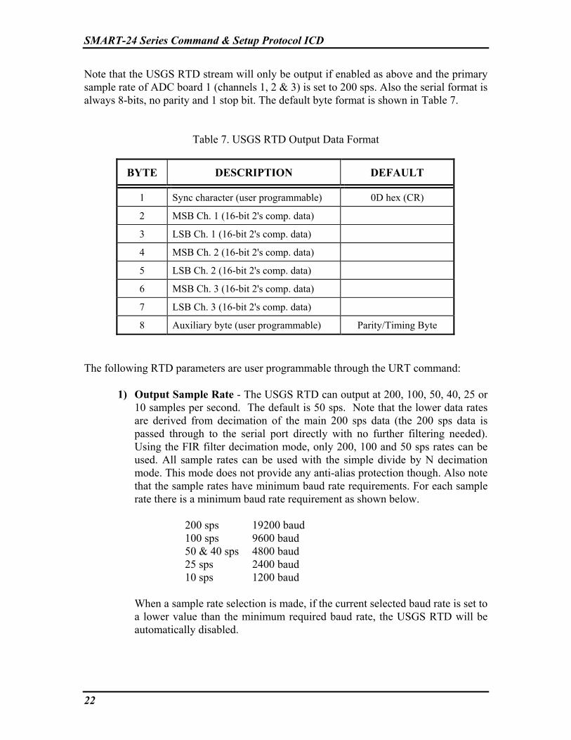
Note that the USGS RTD stream will only be output if enabled as above and the primary sample rate of ADC board 1 (channels 1, 2 & 3) is set to 200 sps. Also the serial format is always 8-bits, no parity and 1 stop bit. The default byte format is shown in Table 7.
Table 7. USGS RTD Output Data Format
BYTE DESCRIPTION DEFAULT
1 Sync character (user programmable) 0D hex (CR)
2 MSB Ch. 1 (16-bit 2's comp. data)
3 LSB Ch. 1 (16-bit 2's comp. data)
4 MSB Ch. 2 (16-bit 2's comp. data)
5 LSB Ch. 2 (16-bit 2's comp. data)
6 MSB Ch. 3 (16-bit 2's comp. data)
7 LSB Ch. 3 (16-bit 2's comp. data)
8 Auxiliary byte (user programmable) Parity/Timing Byte
The following RTD parameters are user programmable through the URT command:
1) Output Sample Rate - The USGS RTD can output at 200, 100, 50, 40, 25 or 10 samples per second. The default is 50 sps. Note that the lower data rates are derived from decimation of the main 200 sps data (the 200 sps data is passed through to the serial port directly with no further filtering needed). Using the FIR filter decimation mode, only 200, 100 and 50 sps rates can be used. All sample rates can be used with the simple divide by N decimation mode. This mode does not provide any anti-alias protection though. Also note that the sample rates have minimum baud rate requirements. For each sample rate there is a minimum baud rate requirement as shown below.
200 sps 19200 baud 100 sps 9600 baud 50 & 40 sps 4800 baud 25 sps 2400 baud 10 sps 1200 baud When a sample rate selection is made, if the current selected baud rate is set to
a lower value than the minimum required baud rate, the USGS RTD will be automatically disabled.

SMART-24 Series Command & Setup Protocol ICD
23
2) Sync Character - The USGS RTD sync character (the first byte of the data block) is user selectable in the range 00 to FF hex. The default is a carriage return (CR) - 0D hex.
3) Output Data Format - The USGS RTD can output data in either 16-bit 2's
complement or offset binary formats as shown below. The default is 16-bit 2's complement.
2’s Complement Format
+Full Scale - 0111 1111 1111 1111 (7FFFh) (32767) +1 bit - 0000 0000 0000 0001 (0001h) (1) 0 - 0000 0000 0000 0000 (0000h) (0) -1 bit - 1111 1111 1111 1111 (FFFFh) (-1) -Full Scale - 1000 0000 0000 0000 (0000h) (-32768)
Offset Binary Format
+Full Scale - 1111 1111 1111 1111 (FFFFh) (65535) 0 - 1000 0000 0000 0000 (8000h) (32768) -Full Scale - 0000 0000 0000 0000 (0000h) (0)
Note that the SMART-24 is a 24-bit instrument. The unit internally
compensates and scales the data to 16-bits for this output in such a way as to correct for internal calibration data, gain, etc. to utilize the full 16-bit dynamic range. So for a +/-2g accelerometer, the full scale will be a true 16-bit full scale value (+2g = 32767, -2g = -32768).
4) Output Data Byte Order - The USGS RTD can output each 16-bit data word
in either MSB/LSB or LSB/MSB byte orders. The default is MSB/LSB. 5) Auxiliary Byte Type - The USGS RTD auxiliary byte (the last byte of the
data block) is a dual-purpose byte that can be programmed to be a simple End of Block (EOB) character (similar to the sync character) or a Parity/Timing check byte. The default is the Parity/Timing byte type.
As a Timing/Parity check byte, the auxiliary byte contains parity check bits
(programmable for even or odd parity) in data bits 0 to 5 for the six data bytes (bytes 2 to 7 respectively). Bit 6 and Bit 7 are used for timing information as described below.
As an EOB character, the auxiliary byte character is user selectable in the
range 00 to FF hex.

SMART-24 Series Command & Setup Protocol ICD
24
6) Auxiliary Byte Parity Mode - If the Auxiliary Byte Type is set to the Timing/Parity type, this parameter sets the parity type used for bits 0 to 5. Even or odd parity can be selected. The default is even parity.
7) Auxiliary Byte Timing Mode - If the Auxiliary Byte Type is set to the
Timing/Parity type, this parameter sets the timing used for bits 6 & 7 as follows:
• Mode 0 – Bit 7 is set to a 1 for the sample block that represents the
first sample of a second. At all other times it will be a 0. Bit 6 is not used and set to 0.
• Mode 1 - Bit 7 is set to a 1 for the sample block that represents the first sample of a second. At all other times it will be a 0. Bit 6 is set to a 1 for the sample block that represents the first sample of the hour. At all other times it will be a 0. On the first sample of the first second of the hour, both bits 6 & 7 will be a 1 at the same time.
• Mode 2 - Bit 7 is set to a 1 for the sample block that represents the first sample of a second. At all other times it will be a 0. Bit 6 is used to transmit a 32-bit unsigned integer value representing the number of seconds since January 1, 1970. When bit 7 is set a 1, bit 6 will be data bit 0 (LSB) of this 32-bit value. Then for the next 31 sample blocks, bit 6 will contain the value of data bits 1 to 31 of the time code. For the remainder of the sample blocks, this bit will be a 0. Note that this mode should not be used for sample rates lower than 40 sps.
8) Auxiliary Byte Character - If the Auxiliary Byte Type is set to the EOB
Character type, this parameter sets the Auxiliary Byte Character and is user selectable in the range 00 to FF hex. The default is a line feed (LF) - 0A hex.
9) Sample Rate Decimation Mode – To generate the USGS RTD data, the
samples must be decimated (except for 200 sps output). This parameter allows the user to select either FIR filter decimation or simple divide by N decimation.
With FIR filter decimation, full anti-aliasing protection is provided, but with a
time delay of 495mS for 100 sps and 830mS for 50 sps from real time. Also only 100 sps and 50 sps can be generated with the current FIR decimation filter.
With the simple divide by N decimation, all output sample rates can be used
down to 10 sps with a fixed time delay of 175mS for each. However no anti-aliasing protection is provided for frequencies below 80 Hz.

SMART-24 Series Command & Setup Protocol ICD
25
3.6.1.3 TCP/IP Related Parameters 3.6.1.3.1 IPA – Set IP Address IPA – Set a port’s IP address when used in TCP/IP mode. IPA_[port],[IP address]<ENTER> Where: [port] – TCP/IP port; 1E = Ethernet port 1, 2E = Ethernet port 2,
1S = Serial port 1 (I/O 1), 2S = Serial port 2 (I/O 2), 3S = Debug port, 4S = IRDA port or 5S = PCMCIA serial port.
[IP Address] – IP address; xxx.xxx.xxx.xxx (Factory defaults: 1E = 192.168.0.1 2E = 192.168.0.2 1S = 192.168.0.3 2S = 192.168.0.4 3S = 192.168.0.5 4S = 192.168.0.6 5S = 192.168.0.7) [? will return the current value] Example: IPA_1E,192.168.0.1<ENTER> IPA_1E,?<ENTER> Query IPA_1E,192.168.0.1<CR><LF> Returned string 3.6.1.3.2 IPM – Set IP Mask IPM – Set a port’s IP address mask when used in TCP/IP mode. IPM_[port],[IP mask]<ENTER> Where: [port] – TCP/IP port; 1E = Ethernet port 1, 2E = Ethernet port 2,
1S = Serial port 1 (I/O 1), 2S = Serial port 2 (I/O 2), 3S = Debug port, 4S = IRDA port or 5S = PCMCIA serial port.
[IP mask] – IP address mask; xxx.xxx.xxx.xxx (Factory default is 255.255.255.0 for all ports.) [? will return the current value] Example:

SMART-24 Series Command & Setup Protocol ICD
26
IPM_1E,255.255.255.0<ENTER> IPM_1E,?<ENTER> Query IPM_1E,255.255.255.0<CR><LF> Returned string 3.6.1.3.3 IPG – Set IP Gateway IPG – Set a port’s IP gateway address when used in TCP/IP mode. IPG_[port],[IP gateway]<ENTER> Where: [port] – TCP/IP port; 1E = Ethernet port 1, 2E = Ethernet port 2,
1S = Serial port 1 (I/O 1), 2S = Serial port 2 (I/O 2), 3S = Debug port, 4S = IRDA port or 5S = PCMCIA serial port.
[IP gateway] – IP gateway address; xxx.xxx.xxx.xxx (Factory default is 192.168.0.255 for all ports.)
[? will return the current value] Example: IPG_1E,192.168.0.254<ENTER> IPG_1E,?<ENTER> Query IPG_1E,192.168.0.254<CR><LF> Returned string 3.6.1.3.4 IPH – Set IP Host Name IPH – Set the global IP Host Name when used in TCP/IP mode. The same host name is used for all TCP/IP connections. IPH_[IP host name]<ENTER> Where: [IP host name] – IP host name; “sd24sn1099” maximum length is 63 characters (Factory default is ‘sT24snXXXX’, where: T = type {d = digitizer, r = recorder, a = accelerometer and b = borehole} XXXX = unit serial number) [? will return the current value] Example:

SMART-24 Series Command & Setup Protocol ICD
27
IPH_sd24sn1099<ENTER> IPH_?<ENTER> Query IPH_ sd24sn1099<CR><LF> Returned string 3.6.1.3.5 IPD – Set IP Domain Name IPD – Set a port’s IP Domain name when used in TCP/IP mode. IPD_[port],[IP domain name]<ENTER> Where: [port] – TCP/IP port; 1E = Ethernet port 1, 2E = Ethernet port 2,
1S = Serial port 1 (I/O 1), 2S = Serial port 2 (I/O 2), 3S = Debug port, 4S = IRDA port or 5S = PCMCIA serial port.
[IP domain name] – IP Domain name; smart24.net maximum length is 63 characters (Factory default is ‘smart24.net’ for all ports.) [? will return the current value] Example: IPD_1E,smart.domain <ENTER> IPD_1E,?<ENTER> Query IPD_1E,smart.domain<CR><LF> Returned string 3.6.1.3.6 IPN – Set IP DNS Server IPN – Set a port’s IP DNS sever address when used in TCP/IP mode. Note that DNS services are not currently used. IPN_[port],[IP DNS sever]<ENTER> Where: [port] – TCP/IP port; 1E = Ethernet port 1, 2E = Ethernet port 2,
1S = Serial port 1 (I/O 1), 2S = Serial port 2 (I/O 2), 3S = Debug port, 4S = IRDA port or 5S = PCMCIA serial port.
[IP DNS sever] – IP DNS sever address; xxx.xxx.xxx.xxx (Factory default is 0.0.0.0 for all ports.)
[? will return the current value] Example:

SMART-24 Series Command & Setup Protocol ICD
28
IPN_1E,245.134.1.254<ENTER> IPN_1E,?<ENTER> Query IPN_1E,245.134.1.254<CR><LF> Returned string 3.6.1.3.7 IDM – Set IP Data Mode IDM – Set a port’s IP data mode to enable or disable the CD 1.1 data stream. IDM_[port],[IP mode]<ENTER> Where: [port] – TCP/IP port; 1E = Ethernet port 1, 2E = Ethernet port 2,
1S = Serial port 1 (I/O 1), 2S = Serial port 2 (I/O 2), 3S = Debug port, 4S = IRDA port or 5S = PCMCIA serial port.
[IP mode] – IP transmission mode; 0 = CD 1.1 disabled, 1 = CD 1.1 enabled. (Factory default is 1, enabled, for all ports.) [? will return the current value] Example: IDM_1E,1<ENTER> IDM_1E,?<ENTER> Query IDM_1E,1<CR><LF> Returned string 3.6.1.3.8 IPE – Set IP Port Enabled/Disabled IPE– Enable or disable a TCP/IP port. IPE_[port],[enable/disable]<ENTER> Where: [port] – TCP/IP port; 1E = Ethernet port 1, 2E = Ethernet port 2,
1S = Serial port 1 (I/O 1), 2S = Serial port 2 (I/O 2), 3S = Debug port, 4S = IRDA port or 5S = PCMCIA serial port.
[enable/disable] – Enable/Disable; 0 = disabled, 1 = enabled. (Factory default is 1, enabled, for all ports.) [? will return the current value] Example: IPE_1E,1<ENTER>

SMART-24 Series Command & Setup Protocol ICD
29
IPE_1E,?<ENTER> Query IPE_1E,1<CR><LF> Returned string 3.6.1.3.9 ISA – Set IP Port PPP Server IP Address ISA– Set a TCP/IP port PPP server IP address. Note this is only valid for TCP/IP over a serial port. ISA _[port],[ IP Address]<ENTER> Where: [port] – TCP/IP port; 1S = Serial port 1 (I/O 1), 2S = Serial port 2 (I/O 2),
3S = Debug port, 4S = IRDA port or 5S = PCMCIA serial port. [IP Address] – IP address; xxx.xxx.xxx.xxx (Factory defaults: 1S = 192.168.0.30 2S = 192.168.0.40 3S = 192.168.0.50 4S = 192.168.0.60 5S = 192.168.0.70) [? will return the current value] Example: ISA_1S,192.168.0.1<ENTER> ISA_1S,?<ENTER> Query ISA_1S,192.168.0.1<CR><LF> Returned string 3.6.1.3.10 ISM – Set IP Port PPP Server IP Mask ISM– Set a TCP/IP port PPP server IP mask. Note this is only valid for TCP/IP over a serial port. ISM _[port],[ IP Mask]<ENTER> Where: [port] – TCP/IP port; 1S = Serial port 1 (I/O 1), 2S = Serial port 2 (I/O 2),
3S = Debug port, 4S = IRDA port or 5S = PCMCIA serial port. [IP Mask] – IP mask; xxx.xxx.xxx.xxx (Factory default is 255.255.255.0 for all ports.) [? will return the current value] Example:

SMART-24 Series Command & Setup Protocol ICD
30
ISM_1S,255.255.255.0<ENTER> ISM_1S,?<ENTER> Query ISM_1S, 255.255.255.0<CR><LF> Returned string 3.6.1.3.11 ICA – Set IP Port PPP Server Remote Client IP Address ICA– Set a TCP/IP port PPP server remote client IP address. Note this is only valid for TCP/IP over a serial port and is the IP address given to a connecting remote PPP client. ICA _[port],[ IP Address]<ENTER> Where: [port] – TCP/IP port; 1S = Serial port 1 (I/O 1), 2S = Serial port 2 (I/O 2),
3S = Debug port, 4S = IRDA port or 5S = PCMCIA serial port. [IP Address] – IP address; xxx.xxx.xxx.xxx (Factory defaults: 1S = 192.168.0.31 2S = 192.168.0.41 3S = 192.168.0.51 4S = 192.168.0.61 5S = 192.168.0.71) [? will return the current value] Example: ICA_1S,192.168.0.2<ENTER> ICA_1S,?<ENTER> Query ICA_1S,192.168.0.2<CR><LF> Returned string 3.6.1.3.12 ANO – Anonymous FTP Access Enable/Disable ANO– Enable or disable anonymous FTP server access. ANO_[enable/disable]<ENTER> Where: [enable/disable] – Enable/Disable; 0 = disabled, 1 = enabled. (Factory default is 0, disabled.) [? will return the current value] Example: ANO_1<ENTER>

SMART-24 Series Command & Setup Protocol ICD
31
ANO_?<ENTER> Query ANO_1<CR><LF> Returned string 3.6.1.3.13 IPP – Set Primary IP Port IPP – Set the Primary IP Port that will allow the SMART-24 to connect to distant IP subnets or to the Internet. IPP_[port]<ENTER> Where: [port] – TCP/IP port; 1E = Ethernet port 1, 2E = Ethernet port 2,
1S = Serial port 1 (I/O 1), 2S = Serial port 2 (I/O 2), 3S = Debug port, 4S = IRDA port or 5S = PCMCIA serial port.
(Factory default is 1E) [? will return the current value] Example: IPP_1SENTER> IPP_?<ENTER> Query IPP_1S<CR><LF> Returned string 3.6.1.3.14 SPH – Set PPP Connection Handshake Mode SPH – Sets the PPP Connection Handshake Mode. On PPP startup, some PPP connections require special handshaking to start the connection. The SMART-24 now supports Microsoft PPP handshaking and Lantronix SCS handshaking. SPH_[port],[mode]<ENTER> Where: [port] – Serial port 1 (I/O 1), 2 (I/O 2), 3 (debug), 4 (IRDA) or 5 (PCMCIA). [mode] – 0 = Microsoft PPP Handshake Mode 1 = Lantronix SCS PPP Handshake Mode (Factory default is 0 = Microsoft PPP Handshake Mode for all ports.) [? will return the current value] Example: SPH_1,1<ENTER>

SMART-24 Series Command & Setup Protocol ICD
32
SPH_1,?<ENTER> Query SPH_1,1<CR><LF> Returned string 3.6.1.4 CD 1.1 Related Parameters NOTE: The Smart24 provides four CD 1.1 profiles that can be configured and enabled to send data to four different destinations. 3.6.1.4.1 CSN - Set CD Site Name CSN - Set the CD 1.1 site name. This is at the same time the station name in the Earthworm data packet when sending Earthworm data is enabled. CSN_[profile],[site name]<ENTER> Where: [profile] – CD 1.1 profile to reference (1 to 4) or A for all. [site name] – CD 1.1 site name (5 characters maximum); “S1000” (Factory default is ‘SXXXX’ where XXXX is the unit’s serial number.) [? will return the current value] Example: CSN_1,SITE1<ENTER> CSN_1,?<ENTER> Query CSN_1,SITE1<CR><LF> Returned string 3.6.1.4.2 CLN - Set CD Location Name CLN - Set the CD 1.1 location name for each channel. This is at the same time the location name in the Earthworm data packet when sending Earthworm data is enabled. CLN_[profile],[channel],[location name]<ENTER> Where: [profile] – CD 1.1 profile to reference (1 to 4) or A for all. [channel] – Channel number; 1P, 2P, 3P, 4P, 5P or 6P (primary data streams); 1S, 2S, 3S, 4S, 5S or 6S (secondary data streams); 1A or 2A (I/O Aux input streams); 1M, 2M, 3M, 4M, 5M or 6M (mass position streams). [location name] – CD 1.1 location name (2 characters maximum); “01” (Factory defaults: ?P, ?A & ?M = ‘01’

SMART-24 Series Command & Setup Protocol ICD
33
?S = ‘02’) [? will return the current value] Example: CLN_1,1P,01<ENTER> CLN_1,1P,?<ENTER> Query CLN_1,1P,01<CR><LF> Returned string 3.6.1.4.3 CCN - Set CD Channel Name CCN - Set the CD 1.1 channel name for each data channel. This is at the same time the component name in the Earthworm data packet when sending Earthworm data is enabled. CCN_[profile],[channel],[channel name]<ENTER> Where: [profile] – CD 1.1 profile to reference (1 to 4) or A for all. [channel] – Channel number; 1P, 2P, 3P, 4P, 5P or 6P (primary data streams); 1S, 2S, 3S, 4S, 5S or 6S (secondary data streams); 1A or 2A (I/O Aux input streams); 1M, 2M, 3M, 4M, 5M or 6M (mass position streams). [channel name] – CD 1.1 channel name (3 characters maximum); “ch1” (Factory defaults: 1P = ‘c1p’, 2P = ‘c2p’, 3P = ‘c3p’ 4P = ‘c4p’, 5P = ‘c5p’, 6P = ‘c6p’ 1S = ‘c1s’, 2S = ‘c2s’, 3S = ‘c3s’ 4S = ‘c4s’, 5S = ‘c5s’, 6S = ‘c6s’ 1A = ‘c1a’, 2A = ‘c2a’ 1M = ‘c1m’, 2M = ‘c2m’, 3M = ‘c3m’ 4M = ‘c4m’, 5M = ‘c5m’, 6M = ‘c6m’) [? will return the current value] Example: CCN_1,1P,C1P<ENTER> CCN_1,?<ENTER> Query CCN_1,C1P<CR><LF> Returned string 3.6.1.4.4 CDT - Set CD Data Type CDT - Set the CD 1.1 data type.
SMART-24 Series Command & Setup Protocol ICD
34
CDT_[profile],[channel],[data type]<ENTER> Where: [profile] – CD 1.1 profile to reference (1 to 4) or A for all. [channel] – Channel number; 1P, 2P, 3P, 4P, 5P or 6P (primary data streams); 1S, 2S, 3S, 4S, 5S or 6S (secondary data streams); 1A or 2A (I/O Aux input streams); 1M, 2M, 3M, 4M, 5M or 6M (mass position streams). [data type] – CD 1.1 data type;
0 = “s4” – Sun Micro IEEE integer (4 bytes) 1 = “s3” – Sun Micro IEEE integer, packed (3 bytes) 2 = “s2” – Sun Micro IEEE short integer (2 bytes) 3 = “i4” – 4-byte integer 4 = “i2” – 2-byte integer (Factory default is 0, “S4” for all channels, other data types are not currently implemented and should not be used.) [? will return the current value] Example: CDT_1,1P,0<ENTER> CDT_1,1P,?<ENTER> Query CDT_1,1P,0<CR><LF> Returned string 3.6.1.4.5 CST - Set CD Sensor Type CST - Set the CD 1.1 sensor type. CST_[profile],[channel],[sensor type]<ENTER> Where: [profile] – CD 1.1 profile to reference (1 to 4) or A for all. [channel] – Channel number; 1P, 2P, 3P, 4P, 5P or 6P (primary data streams); 1S, 2S, 3S, 4S, 5S or 6S (secondary data streams); 1A or 2A (I/O Aux input streams); 1M, 2M, 3M, 4M, 5M or 6M (mass position streams). [sensor type] – CD 1.1 sensor type; 0 – Seismic 1 – hydroacoustic 2 – infrasonic 3 – weather 4 – other 5 – velocity 6 – acceleration
SMART-24 Series Command & Setup Protocol ICD
35
>6 – TBD (Factory defaults: ?P & ?S = 0, seismic ?A & ?M = 4, other) [? will return the current value] Example: CST_1,2P,2<ENTER> CST_1,2P,?<ENTER> Query CST_1,2P,2<CR><LF> Returned string 3.6.1.4.6 CCM - Set CD Compression CCM - Set the CD 1.1 compression mode. CCM_[profile],[mode]<ENTER> Where: [profile] – CD 1.1 profile to reference (1 to 4) or A for all. [mode] – CD 1.1 compression mode: 0 – None 1 – Canadian before signature 2 – Canadian after signature (Not Currently Supported) 3 – Steim before signature (Not Currently Supported) 4 – Steim after signature (Not Currently Supported) (Factory default is 0, none, for all CD profiles.) [? will return the current value] Example: CCM_1,1<ENTER> CCM_1,?<ENTER> Query CCM_1,1<CR><LF> Returned string 3.6.1.4.7 CAM - Set CD Authentication CAM - Set the CD 1.1 authentication mode. CAM_[profile],[mode]<ENTER> Where: [profile] – CD 1.1 profile to reference (1 to 4) or A for all.

SMART-24 Series Command & Setup Protocol ICD
36
[mode] – CD 1.1 authentication mode; 0 = OFF, 1 = ON (Factory default is 0, OFF, for all CD profiles.) [? will return the current value] Example: CAM_1,1<ENTER> CAM_1,?<ENTER> Query CAM_1,1<CR><LF> Returned string 3.6.1.4.8 CCL - Set CD Calib/Calper CCL - Set the CD 1.1 calib/calper values. CCL_[profile],[channel],[mode],[calib],[calper]<ENTER> Where: [profile] – CD 1.1 profile to reference (1 to 4) or A for all. [channel] – Channel number; 1P, 2P, 3P, 4P, 5P or 6P (primary data streams); 1S, 2S, 3S, 4S, 5S or 6S (secondary data streams); 1A or 2A (I/O Aux input streams); 1M, 2M, 3M, 4M, 5M or 6M (mass position streams). [mode] – CD 1.1 calib/calper mode; 0 = OFF, 1 = ON (Factory default is 0, OFF, for all CD profiles & channels.)
[? will return the current values] [calib] – CD 1.1 calib value (Factory default is 0.0 for all CD profiles & channels.) [calper]- CD 1.1 calper value (Factory default is 1.0 for all CD profiles & channels.) Example: CCL_1,2P,1,1.0000,2.0000<ENTER> CCL_1,2P,?<ENTER> Query CCL_1,2P,1,1.0000,2.0000<CR><LF> Returned string 3.6.1.4.9 CDF - Set CD Data Frame Size CDF - Set the CD 1.1 data frame size. CDF_[profile],[size]<ENTER> Where:

SMART-24 Series Command & Setup Protocol ICD
37
[profile] – CD 1.1 profile to reference (1 to 4) or A for all. [size] – CD 1.1 data frame size in seconds (1 to 300 seconds). (Factory default is 10 seconds for all CD profiles.) [? will return the current value] Example: CDF_1,30<ENTER> CDF_1,?<ENTER> Query CDF_1,30<CR><LF> Returned string 3.6.1.4.10 CSF - Set CD SOH Alert Frequency CSF - Set the CD 1.1 SOH alert frame output frequency. CSF_[profile],[frequency]<ENTER> Where: [profile] – CD 1.1 profile to reference (1 to 4) or A for all. [frequency] – CD 1.1 SOH alert frame output frequency in seconds (1 to 86400 seconds). (Factory default is 1 second for all CD profiles.) [? will return the current value] Example: CSF_1,1<ENTER> CSF_1,?<ENTER> Query CSF_1,1<CR><LF> Returned string 3.6.1.4.11 CDA - Set CD Destination IP Address CDA - Set the CD 1.1 destination IP address for a port. CDA_[profile],[IP address]<ENTER> Where: [profile] – CD 1.1 profile to reference (1 to 4) or A for all. [IP Address] – IP address; xxx.xxx.xxx.xxx (Factory default is 192.168.0.201 for all CD profiles.) [? will return the current value]

SMART-24 Series Command & Setup Protocol ICD
38
Example: CDA_1,192.168.0.1<ENTER> CDA_1,?<ENTER> Query CDA_1,192.168.0.1<CR><LF> Returned string 3.6.1.4.12 CCP - Set CD Connection Request Remote Port CCP - Set the CD 1.1 initial connection request remote port number. CCP_[profile],[ remote port]<ENTER> Where: [profile] – CD 1.1 profile to reference (1 to 4) or A for all. [remote port] – Remote port to connect to, 0 – 65536 (Factory default is 9000 for all CD profiles.) [? will return the current value] Example: CCP_1,9000<ENTER> CCP_1,?<ENTER> Query CCP_1,9000<CR><LF> Returned string 3.6.1.4.13 CCE – Set Data Channel Enables CCE – Enable ADC channels for transmission from the selected CD 1.1 profile. CCE_[profile],[channel],[channel]…<ENTER> Where: [profile] – CD 1.1 profile to reference (1 to 4) or A for all. [channel] – Channel number to enable; 1P, 2P, 3P, 4P, 5P or 6P (primary data streams); 1S, 2S, 3S, 4S, 5S or 6S (secondary data streams); 1A or 2A (I/O Aux input streams); 1M, 2M, 3M, 4M, 5M or 6M (mass position streams). Special cases: 0P will enable all primary data streams, 0S will enable all secondary data streams, 0A will enable all aux data streams and 0M will enable all mass position data streams. (Factory defaults: ?S, ?A & ?M are all disabled ?P are enabled if installed in the unit)

SMART-24 Series Command & Setup Protocol ICD
39
[? will return the current value] Example: CCE_1,1P,2P,3P,1S,2S,3S<ENTER> Enable channels 1, 2 and 3 (primary
and secondary). CCE_1,0P,0S,0A,0M<ENTER> Enable all channels. CCE_1,?<ENTER> Query CCE_1,1P,2P,3P,4P,5P,6P,1S,2S,3S,4S,5S,6S <CR><LF> Returned string 3.6.1.4.14 CCD – Set Data Channel Disables CCD – Disable ADC channels for transmission from the selected CD 1.1 profile. CCD_[profile],[channel],[channel]…<ENTER> Where: [profile] – CD 1.1 profile to reference (1 to 4) or A for all. [channel] – Channel number to disable; 1P, 2P, 3P, 4P, 5P or 6P (primary data streams); 1S, 2S, 3S, 4S, 5S or 6S (secondary data streams); 1A or 2A (I/O Aux input streams); 1M, 2M, 3M, 4M, 5M or 6M (mass position streams). Special cases: 0P will disable all primary data streams, 0S will disable all secondary data streams, 0A will disable all aux data streams and 0M will disable all mass position data streams. Example: CCD_1,4P,5P,6P,4S,5S,6S<ENTER> Disable channels 4, 5 and 6 (primary
and secondary). CCD_1,0P,0S,0A,0M<ENTER> Disable all channels. 3.6.1.4.15 CDE – Enable/Disable CD Profile CDE – Enable or disable a CD 1.1 profile. CDE_[profile],[enable/disable]<ENTER> Where: [profile] – CD 1.1 profile to reference (1 to 4) or A for all. [enable/disable] – Enable/Disable; 0 = Disable, 1 = Enable (Factory default is 1, enabled, for CD profile 1 and 0, disabled, for CD profiles 2, 3 & 4.)

SMART-24 Series Command & Setup Protocol ICD
40
[? will return the current value] Example: CDE_1,1<ENTER> CDE_1,?<ENTER> Query CDE_1,1<CR><LF> Returned string 3.6.1.4.16 CRT – Set CD Connection Request Timeout CRT – Set this profile’s CD 1.1 connection request timeout in minutes. CRT_[profile],[timeout]<ENTER> Where: [profile] – CD 1.1 profile to reference (1 to 4) or A for all. [timeout] – Connect Request Timeout (1 to 65535 minutes) (Factory default is 2 minutes for all CD profiles.) [? will return the current value] Example: CRT_1,10<ENTER> CRT_1,?<ENTER> Query CRT_1,10<CR><LF> Returned string 3.6.1.4.17 CIP – Set CD Command Input Port CIP – Set this profile’s CD 1.1 command input port. Note that only the value set for CD profile 1 is used. All others are ignored. CIP_[profile],[port]<ENTER> Where: [profile] – CD 1.1 profile to reference (1 to 4) or A for all. [remote port] – Port to listen to for CD commands, 0 – 65536 (Factory default is 8000 for all CD profiles.) [? will return the current value] Example: CIP_1,9010<ENTER>

SMART-24 Series Command & Setup Protocol ICD
41
CIP_1,?<ENTER> Query CIP_1,9010<CR><LF> Returned string 3.6.1.4.18 CRR – Set CD Connection Request Retry CRR – Set this profile’s CD 1.1 connection request retry period in minutes. CRR_[profile],[retry]<ENTER> Where: [profile] – CD 1.1 profile to reference (1 to 4) or A for all. [retry] – Connect Request Retry (1 to 65535 minutes) (Factory default is 2 minutes for all CD profiles.) [? will return the current value] Example: CRR_1,10<ENTER> CRR_1,?<ENTER> Query CRR_1,10<CR><LF> Returned string 3.6.1.4.19 CNC – Set CD Creator Name CNC – Set this profile’s CD 1.1 creator name. CNC_[profile],[creator name]<ENTER> Where: [profile] – CD 1.1 profile to reference (1 to 4) or A for all. [creator name] - Creator Name (up to 8 characters); “S1000” (Factory default is ‘SXXXX’ where XXXX is the unit’s serial number for all CD profiles.) [? will return the current value] Example: CNC_1,SMART24<ENTER> CNC_1,?<ENTER> Query CNC_1,SMART24<CR><LF> Returned string

SMART-24 Series Command & Setup Protocol ICD
42
3.6.1.4.20 CNS – Set CD Station Name CNS – Set this profile’s CD 1.1 station name. This is at the same time the network name in the Earthworm data packet when sending Earthworm data is enabled. CNS_[profile],[station name]<ENTER> Where: [profile] – CD 1.1 profile to reference (1 to 4) or A for all. [station name] - Station Name (up to 8 characters); “S1000” (Factory default is ‘SXXXX’ where XXXX is the unit’s serial number for all CD profiles.) [? will return the current value] Example: CNS_1,SMART24<ENTER> CNS_1,?<ENTER> Query CNS_1,SMART24<CR><LF> Returned string 3.6.1.4.21 CDS – Set CD Data Frame Save Size CDS – Set this profile’s CD 1.1 data frame save size. This will be the number of data frames to save and restore for retransmitting in case of a connection drop. [NOTE: This command is intended for debugging purposes and should only be used at the direction of Geotech technical support.] CDS_[profile],[size]<ENTER> Where: [profile] – CD 1.1 profile to reference (1 to 4) or A for all. [size] – Number of data frames to save and restore. (1 to 600 frames) (Factory default is 5 frames for all CD profiles.) [? will return the current value] Example: CDS_1,10<ENTER> CDS_1,?<ENTER> Query CDS_1,10<CR><LF> Returned string

SMART-24 Series Command & Setup Protocol ICD
43
3.6.1.4.22 CSS – Set CD SOH Frame Save Size CSS – Set this profile’s CD 1.1 SOH frame save size. This will be the number of SOH frames to save and restore for retransmitting in case of a connection drop. [NOTE: This command is intended for debugging purposes and should only be used at the direction of Geotech technical support.] CSS_[profile],[size]<ENTER> Where: [profile] – CD 1.1 profile to reference (1 to 4) or A for all. [size] – Number of SOH frames to save and restore. (1 to 600 frames) (Factory default is 5 frames for all CD profiles.) [? will return the current value] Example: CSS_1,10<ENTER> CSS_1,?<ENTER> Query CSS_1,10<CR><LF> Returned string 3.6.1.4.23 CBF – Enable/Disable CD Backfill Mode CBF – Enable/disable the CD 1.1 backfill mode. CBF_[profile],[enable/disable]<ENTER> Where: [profile] – CD 1.1 profile to reference (1 to 4) or A for all. [enable/disable] – Enable/disable CD 1.1 backfill mode:
0 – Backfill (normal CD 1.1 LIFO or FIFO) 1 – No backfill (old data is flushed on a new connection)
(Factory default is 0, backfill mode, for all CD profiles.) [? will return the current value] Example: CBF_1,1<ENTER> CBF_1,?<ENTER> Query CBF_1,1<CR><LF> Returned string

SMART-24 Series Command & Setup Protocol ICD
44
3.6.1.4.24 CBM – Set CD Backfill Mode CBM - Set the CD 1.1 backfill mode as normal CD 1.1 LIFO or FIFO. CBM_[profile],[mode]<ENTER> Where: [profile] – CD 1.1 profile to reference (1 to 4) or A for all. [mode] – CD 1.1 backfill mode: 0 – Normal CD 1.1 LIFO backfill mode 1 – FIFO backfill mode (Factory default is 0, normal CD 1.1 LIFO backfill mode, for all CD profiles.) [? will return the current value] Example: CBM_1,1<ENTER> CBM_1,?<ENTER> Query CBM_1,1<CR><LF> Returned string 3.6.1.4.25 CTM – Enable/Disable CD Send Triggered Data CTM – Enable/disable CD 1.1 send triggered data on primary channels. When this option is enabled, primary channels are sent as triggered data, and secondary channels as continuous data. Triggered data is sent out during event recording, set up as given in sections 3.8.1.2 and 3.8.1.3. By default this option is disabled on all CD1.1 profiles, i.e. all primary and secondary channels are sent as continuous data. CTM_[profile],[enable/disable]<ENTER> Where: [profile] – CD 1.1 profile to reference (1 to 4) or A for all. [enable/disable] – Enable/Disable; 0 = Disable, 1 = Enable (Factory default is disabled, for all CD profiles.) [? will return the current value] Example: CTM_1,1<ENTER> CTM_1,?<ENTER> Query CTM_1,1<CR><LF> Returned string
SMART-24 Series Command & Setup Protocol ICD
45
3.6.1.5 Earthworm Related Parameters NOTE: The Smart24 provides four CD 1.1 profiles that can be configured and enabled to send data to four different destinations. First profile can be configured to send data to a Earthworm destination, using the Earthworm export protocol (instead of CD1.1). 3.6.1.5.1 EWE – Enable/Disable Earthworm Profile EWE – Enable or disable an Earthworm profile. [Note:This command only works for CD Profile 1 at this time.] EWE_[profile],[enable/disable]<ENTER> Where:
[profile] – Earthworm profile to reference (1 to 4) or A for all. Currently only profile 1 can be Earthworm enabled.
[enable/disable] – Enable/Disable; 0 = Disable, 1 = Enable (Factory default is 0, disabled, for CD profile 1) [? will return the current value] Example: EWE_1,1<ENTER> EWE_1,?<ENTER> Query EWE_1,1,1<CR><LF> Returned string 3.6.1.5.2 EWI – Set Earthworm Installation ID EWI – Set this profile’s Earthworm installation ID. [Note:This command only works for CD Profile 1 at this time.] EWI_[profile],[inst_id]<ENTER> Where: [profile] – Earthworm profile to reference (1 to 4) or A for all.
[inst_id] - Earthworm installation ID, 0-255 (Factory default is ‘255’.) [? will return the current value] Example: EWI_1,0<ENTER>

SMART-24 Series Command & Setup Protocol ICD
46
EWI_1,?<ENTER> Query EWI_1,0<CR><LF> Returned string 3.6.1.5.3 EWM – Set Earthworm Module ID EWM – Set this profile’s Earthworm module ID. [Note:This command only works for CD Profile 1 at this time.] EWM_[profile],[module_id]<ENTER> Where: [profile] – Earthworm profile to reference (1 to 4) or A for all.
[module_id] - Earthworm module ID, 0-255 (Factory default is ‘0’.) [? will return the current value] Example: EWM_1,100<ENTER> EWM_1,?<ENTER> Query EWM_1,100<CR><LF> Returned string 3.6.1.5.4 EWS – Set Earthworm Client/Server Mode EWS – Set either an Earthworm Client Mode where the SMART-24 will try to establish the data connection, or a Server Mode where the SMART-24 will open a port to listen on and wait for an incoming Earthworm connection. [Note:This command only works for CD Profile 1 at this time.] EWS_[profile],[mode]<ENTER> Where: [profile] – Earthworm profile to reference (1 to 4) or A for all.
[mode] – Client/Server mode; 0 = Client Mode, 1=Server Mode (Factory default is ‘0’, Client Mode)
[? will return the current value] Example: EWS_1,1<ENTER> EWM_1,?<ENTER> Query EWM_1,1<CR><LF> Returned string

SMART-24 Series Command & Setup Protocol ICD
47
3.6.2 Calibration Parameters Note that the calibration parameters are not accepted and enabled until a Calibration Go (CAG) command is issued. All parameters should be first setup as necessary and then one CAG command issued. 3.6.2.1 Calibration Related Parameters 3.6.2.1.1 CAO – Set Calibration Output Signal CAO – Set the calibration output signal type. Required for both immediate and scheduled calibrations. CAO_[mode] ,[type]<ENTER> Where: [mode] – Calibration mode; I = Immediate, S = Scheduled [type] – Calibration signal type: 0 – Sine wave 1 – Noise 2 – Pulse 3 – Pseudo random binary 4 – Time Pulse (5 sec pulse every minute, 15 sec pulse every 10 minutes) 5 – One Pulse Per Second (PPS), 50% duty cycle 6 – One Pulse Per Minute (PPM), 50% duty cycle 7 – One Pulse Per Hour (PPH), 50% duty cycle 8 – None (Disabled) (Factory default is 0, sine wave.) [? will return the current value] Example: CAO_I,0<ENTER> CAO_I,?<ENTER> Query CAO_I,0<CR><LF> Returned string 3.6.2.1.2 CAA – Set Calibration Amplitude CAA – Set the calibration amplitude in volts. Required for both immediate and scheduled calibrations. CAA_[mode],[amplitude]<ENTER>

SMART-24 Series Command & Setup Protocol ICD
48
Where: [mode] – Calibration mode; I = Immediate, S = Scheduled [amplitude] – Calibration amplitude in volts (zero to peak, -5.000000 to +5.000000 volts). (Factory default is +1.0 volts.) [? will return the current value] Example: CAA_S,2.500<ENTER> CAA_S,?<ENTER> Query CAA_S,2.500<CR><LF> Returned string 3.6.2.1.3 CAF – Set Calibration Frequency CAF – Set the calibration frequency in hertz. Required for both immediate and scheduled calibrations. (Used for sine wave output only.) CAF_[mode],[frequency]<ENTER> Where: [mode] – Calibration mode; I = Immediate, S = Scheduled [frequency] – Calibration frequency in hertz (0.001 to 100.0 hertz). (Factory default is 1.000 hertz.) [? will return the current value] Example: CAF_I,1.000<ENTER> CAF_I,?<ENTER> Query CAF_I,1.000<CR><LF> Returned string 3.6.2.1.4 CAW – Set Calibration Pulse or Bit Width CAW – Set the calibration pulse or pseudo random binary bit width in seconds. Required for both immediate and scheduled calibrations. (Used for pulse or pseudo random binary outputs only.) CAW_[mode],[width]<ENTER> Where:

SMART-24 Series Command & Setup Protocol ICD
49
[mode] – Calibration mode; I = Immediate, S = Scheduled [width] – Calibration pulse or pseudo random binary bit width in seconds (value must be greater than 0.0 seconds and is limited to 4294.0 seconds). (Factory default is 1.000 second.)
[? will return the current value] Example: CAW_I,0.025<ENTER> CAW_I,?<ENTER> Query CAW_I,0.025<CR><LF> Returned string 3.6.2.1.5 CAD – Set Calibration Duration CAD – Set the calibration duration in seconds. Required for both immediate and scheduled calibrations. CAD_[mode],[duration]<ENTER> Where: [mode] – Calibration mode; I = Immediate, S = Scheduled [duration] – Calibration duration in seconds (value must be greater than 0 seconds). (Factory default is 10 seconds.) [? will return the current value] Example: CAD_S,60<ENTER> CAD_S,?<ENTER> Query CAD_S,60<CR><LF> Returned string 3.6.2.1.6 CAS – Set Calibration Relay State CAS – Set each channel’s calibration output relay state. Required for both immediate and scheduled calibrations. CAS_[mode],[channel],[state]<ENTER> Where:

SMART-24 Series Command & Setup Protocol ICD
50
[mode] – Calibration mode; I = Immediate, S = Scheduled [channel] – Channel number; 1, 2, 3, 4, 5 or 6. [state] – Calibration relay state: 0 – Disabled 1 – Loopback 2 – Sensor (Factory default is 0, disabled, for all channels.) [? will return the current value] Example: CAS_I,1,2<ENTER> CAS_I,1,?<ENTER> Query CAS_I,1,2<CR><LF> Returned string 3.6.2.1.7 CAC – Set Calibration Digital Control Enable CAC – Set the calibration digital control mode on or off. Required for both immediate and scheduled calibrations. CAC_[mode],[control]<ENTER> Where: [mode] – Calibration mode; I = Immediate, S = Scheduled [control] – Calibration digital control: 0 – Analog Mode (Analog output on all enabled channels) 1 – Standard Analog with Digital Control Mode (Analog output on channel 1 (3) with digital control signals). 2 – KS-2000 Analog with Digital Control Mode (Factory default is 0, analog mode.) [? will return the current value] Example: CAC_I,1<ENTER> CAC_I,?<ENTER> Query CAC_I,1<CR><LF> Returned string 3.6.2.1.8 CAI – Set Calibration Interval CAI – Set the calibration interval between scheduled calibrations in seconds. Required for scheduled calibrations only. Note that the interval must be larger than the duration.

SMART-24 Series Command & Setup Protocol ICD
51
CAI_[mode],[interval]<ENTER> Where: [mode] – Calibration mode; I = Immediate, S = Scheduled [interval] – Calibration interval between scheduled calibrations in seconds (value must be greater than 0 seconds and larger than the duration). (Factory default is 3600 seconds.)
[? will return the current value] Example: CAI_S,86400<ENTER> CAI_S,?<ENTER> Query CAI_S,86400<CR><LF> Returned string 3.6.2.1.9 CAR – Set Calibration Repetitions CAR – Set the number of calibration repetitions. Required for scheduled calibrations only. CAR_[mode],[repetitions]<ENTER> Where: [mode] – Calibration mode; I = Immediate, S = Scheduled [interval] – Number of calibration repetitions (value must be greater than 0). (Factory default is 1 repetition.)
[? will return the current value] Example: CAR_S,365<ENTER> CAR_S,?<ENTER> Query CAR_S,365<CR><LF> Returned string 3.6.2.1.10 CAT – Set Calibration Start Time CAT – Set the calibration start time. Required for scheduled calibrations only. CAT_[mode],[time]<ENTER> Where:

SMART-24 Series Command & Setup Protocol ICD
52
[mode] – Calibration mode; I = Immediate, S = Scheduled [time] – Calibration start time; HH:MM:SS,MM/DD/YYYY (Factory default is 00:00:00,01/01/1970.) [? will return the current value] Example: CAT_S,00:00:00,02/19/2003<ENTER> CAT_S,?<ENTER> Query CAT_S,00:00:00,02/19/2003<CR><LF> Returned string 3.6.3 Time and Synchronization Parameters Note that the time and synchronization parameters are accepted immediately and a reboot is not required. 3.6.3.1 Synchronization Related Commands 3.6.3.1.1 TSM – Set Time Synchronization Mode TSM – Sets the time synchronization mode. TSM_[mode]<ENTER> Where: [mode] – Time synchronization mode; 0 = None, 1 = External 1PPS, 2 = GPS Master, 3 = GPS Slave (Factory default is 2, GPS master.) [? will return the current value] Example: TSM_2<ENTER> TSM_?<ENTER> Query TSM_2<CR><LF> Returned string 3.6.3.1.2 JST – Set Jamset Threshold JST – Sets the Jamset threshold in milliseconds. JST_[milliseconds]<ENTER> Where:

SMART-24 Series Command & Setup Protocol ICD
53
[milliseconds] – Jamset threshold in milliseconds (1 to 999 mS). (Factory default is 10 mS.) [? will return the current value] Example: JST_10<ENTER> JST _?<ENTER> Query JST _10<CR><LF> Returned string 3.6.3.2 GPS Related Commands 3.6.3.2.1 GCT – Set GPS Cycle Time GCT – If in the GPS mode, this sets the off time of the GPS between GPS synchronization attempts. If set to 0, the GPS will stay on all the time. GCT_[seconds]<ENTER> Where: [seconds] – Number of seconds to turn the GPS off between synchronizations. 0 will cause the GPS to be turned on all the time. (Factory default is 7200 seconds.) [? will return the current value] Example: GCT_7200<ENTER> GCT_?<ENTER> Query GCT_7200<CR><LF> Returned string 3.6.3.2.2 GPC – Set GPS Configuration GPC – Set the GPS receiver configuration. [NOTE: This command should only be used under the supervision of Geotech technical support to fine tune the GPS configuration for a particular site. The default setting should work well in most situations.] GPC_[PPSPolarity],[PPSOutput],[SelfSurvey],[OpDimension],[DynCode], [ElevMask],[AMUMask],[PDOPMask],[PDOPSwitch]<ENTER> Where:

SMART-24 Series Command & Setup Protocol ICD
54
[PPSPolarity] - PPS Polarity (0 = Positive, 1 = Negative) [PPSOutput] - PPS Output Mode (2 = Always, 3 = At Least 1SV, 4 = At Least 3SV [SelfSurvey] - Self Survey Enable (0 = Disabled, 1 = Enables) [OpDimension] - Operating Dimension (0 = Auto, 1 = Time Only, 2 = 2D, 3 = 3D, 5 = DGPS, 6 = 2D Clock Hold, 7 = Overdetermined Clock) [DynCode] - Dynamics Code (1 = Land, 2 = Sea, 3 = Air, 4 = Static) [ElevMask] - Elevation Mask (0 to 15 corresponding to 0 to 75 degrees in 5 degree increments, default is 2 = 10 degrees) [AMUMask] - AMU Mask (0 to 15 dB, default is 3dB) [PDOPMask] - PDOP Mask (0 to 15 dB, default is 14dB) [PDOPSwitch] - PDOP Switch (0 to 15 dB, default is 10dB) [? will return the current value] Example: GPC_0,2,0,0,1,2,3,14,10<ENTER> GPC_?<ENTER> Query GPC_0,2,0,0,1,2,3,14,10<CR><LF> Returned string 3.6.3.2.3 GOS – Set GPS Local Time Offset GOS – If in the GPS mode, this sets the local time offset from UTC. If set to 0 (default) the SMART-24 will run on UTC time, otherwise on local time with the specified time offset from UTC. [Note: The GOS command does not cause a restart, and will take effect at the next GPS lock.] GOS_[seconds]<ENTER> Where:
[seconds] – Number of seconds representing the local time offset from UTC, +/-43200 seconds (+/-12 hours).
(Factory default is 0 seconds, for UTC.) [? will return the current value] Example: GOS_18000<ENTER> GOS_?<ENTER> Query GOS_18000<CR><LF> Returned string
SMART-24 Series Command & Setup Protocol ICD
55
3.6.3.3 Time Related Commands 3.6.3.3.1 SET – Set Time SET – Sets the current time. SET_[time]<ENTER> Where:
[time] – Time to set on the next 1PPS mark; HH:MM:SS,MM/DD/YYYY [? will return the current value]
Example: SET_15:45:30,02/19/2003<ENTER> SET _?<ENTER> Query SET_15:45:35,02/19/2003<CR><LF> Returned string 3.6.4 Commands 3.6.4.1 Setup and Boot Commands 3.6.4.1.1 ABT – Abort Setup ABT – Abort and discard any new setup parameters that have been loaded. ABT<ENTER> 3.6.4.1.2 ASR – Accept Setup and Reboot ASR – Accept new setup parameters and reboot. ASR<ENTER> 3.6.4.1.3 BTL – Boot into the Boot Loader BTL – Reboot into the boot loader mode. BTL<ENTER>

SMART-24 Series Command & Setup Protocol ICD
56
3.6.4.1.4 GET – Get Setup GET – Dump all current setup parameters. All parameters will be dumped as if their query command had been given. Order is NOT guaranteed, so the receiving software must interpret the full returned string. Any command or parameter that has a query option will be returned using this command. An end string of “END<CR><LF>” will terminate the output. A full GET output example with factory defaults is given in Appendix A. Example: GET<ENTER> Example Output: GET START<CR><LF> TIME: 16:45:20,04/01/2004 SRP_1,200<CR><LF> SRS_2,20<CR><LF> . . . CAR_365<CR><LF> CAT_00:00:00,02/19/2003<CR><LF> GET END<CR><LF> 3.6.4.1.5 OFF – Power Off OFF – Turn power off. OFF<ENTER> 3.6.4.1.6 RBT – Reboot RBT – Reboot with current setup. RBT<ENTER> 3.6.4.1.7 RST – Generate a Harware Reset RST – Causes the unit to generate a watchdog timer hardware reset to restart the unit. This will clear all hardware just as if the unit were powering up. This is different from an ASR or RBT command which only does a software reset and restart. RST HARDWARE<ENTER> Command 3.6.4.1.8 HLP – Help

SMART-24 Series Command & Setup Protocol ICD
57
HLP – Dumps a help listing of commands. HLP<ENTER> 3.6.4.1.9 LGO – Logout LGO – Logs out of the current username and password. LGO<ENTER> 3.6.4.1.10 SFD – Set Factory Defaults SFD – Clears the unit setup back to factory defaults. Must be followed by an ASR command to accept and reboot the unit. SFD<ENTER> 3.6.4.1.11 DDC – Set LCD Data Display Control DDC – Set the LCD data display control mode. DDC_[enable/disable],[fill],[stats]<ENTER> Where: [enable/disable] - 0 = Disable LCD Data Waveform Display 1 = Enable LCD Data Waveform Display (Default) [fill] - 0 = Disable LCD Data Waveform Fill Mode (Dot mode) 1 = Enable LCD Data Waveform Fill Mode (Default) [stats] - 0 = Disable LCD Data Statistics Display 1 = Enable LCD Data Statistics Display (Default) [? will return the current value] Example: DDC_1,1,1<ENTER> DDC_?<ENTER> Query DDC_1,1,1<CR><LF> Returned string 3.6.4.2 Password Commands The Smart24 uses two sets of usernames and passwords. The system username and password is used for direct connect, modem, HTTP, Telnet and FTP access to the unit.

SMART-24 Series Command & Setup Protocol ICD
58
The client username and password are use when a serial port is being used to connect to a PPP server as a remote client. 3.6.4.2.1 PSW – Enter System Password PSW – Enter a password to access the system. PSW_[password]<ENTER> Where:
[password] – Password, 31 characters maximum. (Factory default is ‘changeme’.) Example: PSW_changeme<ENTER> 3.6.4.2.2 SPW – Set System Password SPW – Set (or clear) a new password. SPW_[password]<ENTER> Where:
[password] – Password, 31 characters maximum. Example: SPW_bullwinkle<ENTER> 3.6.4.2.3 USR – Enter System Username USR – Enter a username to access the system. USR_[username]<ENTER> Where:
[username] – User name, 31 characters maximum. (Factory default is ‘smart24’.) Example: USR_smart24<ENTER>

SMART-24 Series Command & Setup Protocol ICD
59
3.6.4.2.4 SUN – Set System Username SUN – Set (or clear) a new username. SUN_[username] <ENTER> Where:
[username] – User name, 31 characters maximum. Example: SUN_rocky<ENTER> 3.6.4.2.5 SCP – Set Client Password SCP – Set (or clear) a new client password. SCP_[password]<ENTER> Where:
[password] – Password, 31 characters maximum. (Factory default is ‘changeme’.) Example: SCP_changeme<ENTER> 3.6.4.2.6 SCU – Set Client Username SCU – Set (or clear) a new client username. SCU_[username]<ENTER> Where:
[username] – User name, 31 characters maximum. (Factory default is ‘smart24’.) Example: SCU_smart24<ENTER>

SMART-24 Series Command & Setup Protocol ICD
60
3.6.4.3 ADC Commands 3.6.4.3.1 OSC – Start ADC Offset Calibration OSC – Perform an offset calibration on an ADC channel. OSC_[board]<ENTER> Where: [board] – Board number; 1 or 2. Example: OSC_2<ENTER> 3.6.4.3.2 OSR – Set Offset Value to Remove from AUX & Mass Position Channels OSR – Set an offset value (in counts) to remove from an AUX or Mass Position Channel in the real time CD 1.1 data streams and data recording file. This value is subtracted from the channel data such that if a channel has an offset of 24 counts, an offset value of 24 would be entered to remove it to 0. OSR_[channel],[offset]<ENTER> Where: [channel] - Channel to set. 1A or 2A (I/O Aux input streams); 1M, 2M, 3M, 4M, 5M or 6M (mass position streams). [offset] - Offset value to subtract (+2048 to –2047). [? will return the current value] (Factory default: 0) Example: OSR_2M,24<ENTER> Subtract 24 counts from Mass Position channel 1. OSR_2M,?<ENTER> Query OSR_2M,24<CR><LF> Returned string 3.6.4.3.3 RCL – ADC Relay Control RCL – Sets the state of the ADC input relay. RCL_[channel],[state]<ENTER> Where:
SMART-24 Series Command & Setup Protocol ICD
61
[channel] – Channel number; 1, 2, 3, 4, 5 or 6. [state] – Relay state; 0 = Signal input, 1 = Short to ground. (Factory default is 0, signal input.) [? will return the current value] Example: RCL_1,1<ENTER> RCL_1,?<ENTER> Query RCL_1,1<CR><LF> Returned string 3.6.4.4 Calibration Commands 3.6.4.4.1 CAG – Calibration Go CAG – Start a calibration command. Note: All of the parameters for a calibration must be set first before issuing this command. For the immediate mode, the calibration will start on the next 1PPS mark after receiving this command. For the scheduled mode, the calibration will start on the next scheduled start time. CAG_[mode]<ENTER> Where: [mode] – Calibration mode; I = Immediate, S = Scheduled Example: CAG_I<ENTER> 3.6.4.4.2 CAH – Calibration Halt CAH – Stop a calibration command. For the immediate mode, the calibration will be terminated on the next 1PPS mark after receiving this command. For the scheduled mode, the calibration will be terminated on the next 1PPS mark after receiving this command if in progress and any further schedule calibrations will be disabled. CAH_[mode]<ENTER> Where: [mode] – Calibration mode; I = Immediate, S = Scheduled Example:

SMART-24 Series Command & Setup Protocol ICD
62
CAH_I<ENTER> 3.6.4.5 Status Commands 3.6.4.5.1 TYP – Get Smart-24 Type TYP – Returns the Smart Series Instrument type. “SMART-24D” – Simple Digitizer “SMART-24R” – Recorder “SMART-24A” – Accelerometer “SMART-24BH” – Borehole Digitizer Example: TYP<ENTER> Command Example Output: TYP_SMART-24D<CR><LF> Returned string 3.6.4.5.2 SOH – Get State of Health SOH – Returns the Smart Series Instrument state of health parameters. Example: SOH<ENTER> Command Example Output:
SOH START TIME: 23:09:25,01/05/2005 PWR_VSW: +11.629 Volts PWR_+5V: +5.025 Volts PWR_+3.3V: +3.259 Volts PWR_+1.8V: +1.783 Volts PWR_+3.3VA: +3.269 Volts PWR_-3.3VA: -3.330 Volts PWR_AUX1: +0.921 Volts PWR_AUX2: +0.965 Volts PWR_TEMP: +27.166 Degree C PWR_VIN: +11.846 Volts PWR_SENSOR1: +11.530 Volts PWR_SENSOR2: +11.530 Volts PWR_FIREWIRE: +0.000 Volts PWR_GPS: +11.214 Volts PWR_USB_HOST: +4.988 Volts PWR_USB: +0.000 Volts

SMART-24 Series Command & Setup Protocol ICD
63
DSP_VCTCXO: +0.003 Volts DSP_+3.3V: +3.278 Volts DSP_GND: +0.000 Volts DSP_+5V: +5.073 Volts DSP_+5VA: +0.003 Volts DSP_+2.5VREF: +2.514 Volts DSP_+3.6VBAT: +3.660 Volts DSP_+1.8V: +1.730 Volts DSP_TEMP: +24.889 Degree C DSP_DIG_IN_1: CLOSED DSP_DIG_IN_2: CLOSED DSP_DIG_IN_3: CLOSED DSP_DIG_IN_4: OPEN DSP_DIG_IN_5: OPEN DSP_DIG_IN_6: OPEN ADC1_CH1_MP: +0.926 Volts ADC1_CH2_MP: +0.975 Volts ADC1_CH3_MP: +1.010 Volts ADC1_+3VA: +2.993 Volts ADC1_-3VA: -2.986 Volts ADC1_+3V: +2.983 Volts ADC1_GND: +0.000 Volts ADC1_TEMP: +25.096 Degree C ETH1_+3.3V: +3.273 Volts ETH1_TEMP: +27.373 Degree C CLK_STATUS: LOCKED CLK_LAST_LOCK: 23:09:24,01/05/2005 CLK_EXT_1PPS: YES CLK_DIFFERENCE: +0.000000183 Seconds CLK_INIT_DIFFERENCE: -0.186812407 Seconds CLK_TEMP: +24.889 Degree C CLK_DAC_VALUE: 2105 GPS_POWER: ON GPS_INITIALIZED: YES GPS_STATUS: LOCKED GPS_LAST_LOCK: 22:57:12,01/05/2005 GPS_STATE: 1 GPS_HEALTH_STATUS: 0x00 GPS_HEALTH_ERROR: 0x01 GPS_MACHINE_ID: 0x61 GPS_MACHINE_STATUS1: 0x00 GPS_MACHINE_STATUS2: 0x01 GPS_NAV_SW_VER: 2.2 GPS_NAV_SW_DATE: 10/05/2000 GPS_SIG_SW_VER: 10.2 GPS_SIG_SW_DATE: 08/23/1999 GPS_LAST_FIX_TYPE: 0x19 GPS_LAST_FIX_SV: 6 GPS_LAST_FIX_UTC_OS: 0 GPS_RECVR_STATUS: 0 GPS_UTC_FLAGS: 0x01 GPS_MINOR_ALARMS: 0x0060 GPS_RECVR_MODE: 0x04 GPS_SURVEY_PROGRESS: 37 GPS_DECODE_STATUS: 0x00 GPS_1PPS_OUTPUT: YES GPS_LATITUDE: +32.895913 Degrees GPS_LONGITUDE: -96.694238 Degrees GPS_ALTITUDE: +164.177370 Meters SOH END
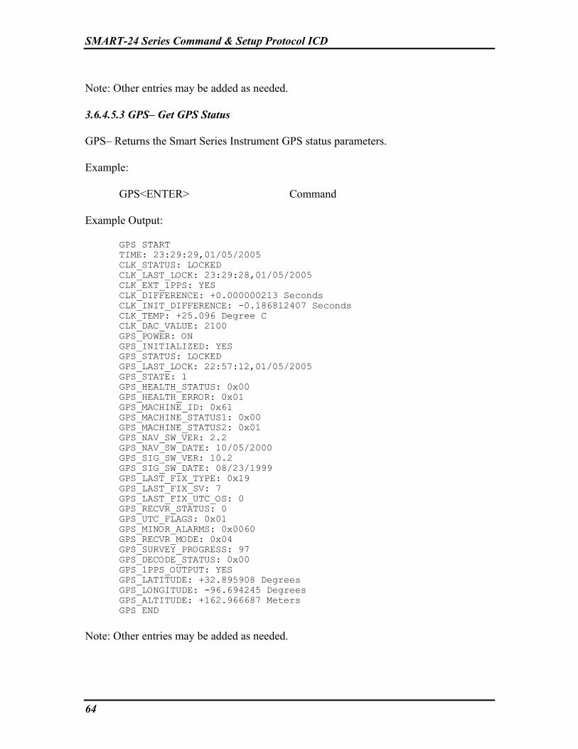
SMART-24 Series Command & Setup Protocol ICD
64
Note: Other entries may be added as needed. 3.6.4.5.3 GPS– Get GPS Status GPS– Returns the Smart Series Instrument GPS status parameters. Example: GPS<ENTER> Command Example Output:
GPS START TIME: 23:29:29,01/05/2005 CLK_STATUS: LOCKED CLK_LAST_LOCK: 23:29:28,01/05/2005 CLK_EXT_1PPS: YES CLK_DIFFERENCE: +0.000000213 Seconds CLK_INIT_DIFFERENCE: -0.186812407 Seconds CLK_TEMP: +25.096 Degree C CLK_DAC_VALUE: 2100 GPS_POWER: ON GPS_INITIALIZED: YES GPS_STATUS: LOCKED GPS_LAST_LOCK: 22:57:12,01/05/2005 GPS_STATE: 1 GPS_HEALTH_STATUS: 0x00 GPS_HEALTH_ERROR: 0x01 GPS_MACHINE_ID: 0x61 GPS_MACHINE_STATUS1: 0x00 GPS_MACHINE_STATUS2: 0x01 GPS_NAV_SW_VER: 2.2 GPS_NAV_SW_DATE: 10/05/2000 GPS_SIG_SW_VER: 10.2 GPS_SIG_SW_DATE: 08/23/1999 GPS_LAST_FIX_TYPE: 0x19 GPS_LAST_FIX_SV: 7 GPS_LAST_FIX_UTC_OS: 0 GPS_RECVR_STATUS: 0 GPS_UTC_FLAGS: 0x01 GPS_MINOR_ALARMS: 0x0060 GPS_RECVR_MODE: 0x04 GPS_SURVEY_PROGRESS: 97 GPS_DECODE_STATUS: 0x00 GPS_1PPS_OUTPUT: YES GPS_LATITUDE: +32.895908 Degrees GPS_LONGITUDE: -96.694245 Degrees GPS_ALTITUDE: +162.966687 Meters GPS END
Note: Other entries may be added as needed.

SMART-24 Series Command & Setup Protocol ICD
65
3.6.4.5.4 IPS– Get IP Status IPS– Returns the Smart Series Instrument TCP/IP status parameters. IPS<ENTER> Command Example: IPS<ENTER> Example Output:
IPS START TIME: 21:54:38,06/04/2004 Total = 0000000002 Odropped = 0000000000 Badsum = 0000000000 Badhlen = 0000000000 Badlen = 0000000000 Badoptions = 0000000000 Badvers = 0000000000 Forward = 0000000000 Noproto = 0000000000 Delivered = 0000000002 Cantforward = 0000000002 CantforwardBA = 0000000000 Expired = 0000000000 Redirectsent = 0000000000 Localout = 0000000003 Localnoroute = 0000000000 CacheHit = 0000000001 CacheMiss = 0000000002 Fragments = 0000000000 Fragdropped = 0000000000 Fragtimeout = 0000000000 Reassembled = 0000000000 Ofragments = 0000000000 Fragmented = 0000000000 Cantfrag = 0000000000 Filtered = 0000000000 TCP Statistics: RcvTotal = 0000000000 RcvShort = 0000000000 RcvHdrSize = 0000000000 RcvBadSum = 0000000000 RcvAfterClose = 0000000000 RcvDupAck = 0000000000 RcvPack = 0000000000 RcvByte = 0000000000 RcvAckPack = 0000000000 RcvAckByte = 0000000000 RcvDupPack = 0000000000 RcvDupByte = 0000000000 RcvPartDupPack = 0000000000 RcvPartDupByte = 0000000000 RcvAfterWinPack = 0000000000

SMART-24 Series Command & Setup Protocol ICD
66
RcvAfterWinByte = 0000000000 RcvOOPack = 0000000000 RcvOOByte = 0000000000 RcvWinUpd = 0000000000 RcvWinProbe = 0000000000 RcvAckTooMuch = 0000000000 SndNoBufs = 0000000000 SndTotal = 0000000003 SndProbe = 0000000000 SndPack (data) = 0000000000 SndByte (data) = 0000000000 SndRexmitPack = 0000000000 SndRexmitByte = 0000000000 SndAcks = 0000000002 SndCtrl = 0000000001 SndUrg = 0000000000 SndWinUp = 0000000000 SegsTimed = 0000000001 RttUpdated = 0000000000 Connects = 0000000000 ConnAttempt = 0000000001 Drops = 0000000000 ConnDrops = 0000000000 Accepts = 0000000000 TimeoutDrops = 0000000000 KeepDrops = 0000000000 DelAck = 0000000000 KeepProbe = 0000000000 PersistTimeout = 0000000000 KeepTimeout = 0000000000 RexmtTimeout = 0000000002 IPS END
Note: Other entries may be added as needed. 3.6.4.5.5 HWS– Get Hardware Status HWS– Returns the Smart Series Instrument hardware status and configuration parameters. HWS<ENTER> Command Example Output:
HWS START TIME: 23:30:42,01/05/2005 SERIAL_NUM: 1056 SMART_TYPE: SMART-24R CURRENT_APP_VER: 1.18 CURRENT_APP_DATE: 12/14/2004 BL_FIRMWARE_TYPE: SMART-24BOOT BL_FIRMWARE_VER: 1.07 BL_FIRMWARE_DATE: 06/17/2004 BANK1_APP_TYPE: SMART-24R BANK1_APP_VER: 1.16 BANK1_APP_DATE: 10/27/2004

SMART-24 Series Command & Setup Protocol ICD
67
BANK2_APP_TYPE: SMART-24R BANK2_APP_VER: 1.17 BANK2_APP_DATE: 11/19/2004 BANK3_APP_TYPE: SMART-24R BANK3_APP_VER: 1.18 BANK3_APP_DATE: 12/14/2004 DSP_BOARD_TYPE: DSP DSP_PART_NUM: 990-60566-0101 DSP_VER_NUM: 01 DSP_ASSY_REV: A DSP_SERIAL_NUM: 1031 DSP_MAN_DATE: 07/14/2004 DSP_FIRMWARE_VER: 1.09 PWR_BOARD_TYPE: POWER PWR_PART_NUM: 990-60567-0101 PWR_VER_NUM: 01 PWR_ASSY_REV: A PWR_SERIAL_NUM: 1056 PWR_MAN_DATE: 11/10/2004 PWR_FIRMWARE_VER: 1.01 ADC1_BOARD_TYPE: 24-BIT ADC ADC1_PART_NUM: 990-60568-0103 ADC1_VER_NUM: 03 ADC1_ASSY_REV: A ADC1_SERIAL_NUM: 1101 ADC1_MAN_DATE: 11/18/2004 ADC1_FIRMWARE_VER: 1.03 ADC1_5VPP_CHANNEL_1_LSB: 0.414490 uVolts ADC1_5VPP_CHANNEL_2_LSB: 0.413006 uVolts ADC1_5VPP_CHANNEL_3_LSB: 0.413007 uVolts ADC1_TOTAL_CHANNEL_1_LSB: 1.657960 uVolts ADC1_TOTAL_CHANNEL_2_LSB: 1.652024 uVolts ADC1_TOTAL_CHANNEL_3_LSB: 1.652028 uVolts ADC2_BOARD_TYPE: NA ADC2_PART_NUM: NA ADC2_VER_NUM: NA ADC2_ASSY_REV: NA ADC2_SERIAL_NUM: NA ADC2_MAN_DATE: NA ADC2_FIRMWARE_VER: NA ADC2_5VPP_CHANNEL_1_LSB: NA ADC2_5VPP_CHANNEL_2_LSB: NA ADC2_5VPP_CHANNEL_3_LSB: NA ADC2_TOTAL_CHANNEL_1_LSB: NA ADC2_TOTAL_CHANNEL_2_LSB: NA ADC2_TOTAL_CHANNEL_3_LSB: NA IO1_BOARD_TYPE: ETHERNET I/O IO1_PART_NUM: 990-60573-0101 IO1_VER_NUM: 01 IO1_ASSY_REV: A IO1_SERIAL_NUM: 1039 IO1_MAN_DATE: 07/07/2004 IO1_FIRMWARE_VER: 1.01 IO1_ETH_MAC_ADDR: 00-50-C2-31-F0-24 IO2_BOARD_TYPE: NA IO2_PART_NUM: NA IO2_VER_NUM: NA IO2_ASSY_REV: NA IO2_SERIAL_NUM: NA IO2_MAN_DATE: NA

SMART-24 Series Command & Setup Protocol ICD
68
IO2_FIRMWARE_VER: NA PCM_BOARD_TYPE: NA PCM_PART_NUM: NA PCM_VER_NUM: NA PCM_ASSY_REV: NA PCM_SERIAL_NUM: NA PCM_MAN_DATE: NA PCM_FIRMWARE_VER: NA PCM_CARD_IN_SLOT_1: NA PCM_CARD_IN_SLOT_2: NA HWS END
Note: Other entries may be added as needed. 3.6.4.5.6 GCS - Get DATA Channel Statistics GCS – Returns the data channel calculated statistics. GCS<ENTER> Command Example Output:
CHANNEL STATISTICS START TIME: 22:25:04,04/29/2005 CH_123_STATS_TIME: 22:25:00,04/29/2005 CH_1_MAX_COUNTS: -6225052 CH_1_MIN_COUNTS: -6225079 CH_1_AVE_COUNTS: -6225058 CH_1_AVE_VOLTS_: -10.030761 CH_2_MAX_COUNTS: +3 CH_2_MIN_COUNTS: -1 CH_2_AVE_COUNTS: +0 CH_2_AVE_VOLTS_: +00.000000 CH_3_MAX_COUNTS: -6 CH_3_MIN_COUNTS: -10 CH_3_AVE_COUNTS: -7 CH_3_AVE_VOLTS_: -00.000011 CH_456_STATS_TIME: 22:25:00,04/29/2005 CH_4_MAX_COUNTS: +2 CH_4_MIN_COUNTS: -5 CH_4_AVE_COUNTS: -1 CH_4_AVE_VOLTS_: -00.000001 CH_5_MAX_COUNTS: +1 CH_5_MIN_COUNTS: -6 CH_5_AVE_COUNTS: -2 CH_5_AVE_VOLTS_: -00.000003 CH_6_MAX_COUNTS: +1 CH_6_MIN_COUNTS: -6 CH_6_AVE_COUNTS: -2 CH_6_AVE_VOLTS_: -00.000003 CHANNEL STATISTICS END
Note: Other entries may be added as needed.

SMART-24 Series Command & Setup Protocol ICD
69
3.6.4.5.7 GPT - Get GPS Satellite Tracking Status GPT – Returns the GPS satellite tracking and signal level report. GPT<ENTER> Command Example Output:
GPS SATELLITE STATUS START TIME: 22:17:20,04/29/2005 GPS_SAT_STATUS_TIME: 22:17:15,04/29/2005 GPS_POWER: ON GPS_SS_VALID: YES GPS_SS_MODE: 3D GPS_SS_MODE_TYPE: AUTOMATIC GPS_SS_NUM_OF_SV: 4 GPS_SS_PDOP: +4.866131 GPS_SS_SV_PRN_1: 15 GPS_SS_SV_PRN_2: 22 GPS_SS_SV_PRN_3: 18 GPS_SS_SV_PRN_4: 09 GPS_SS_SV_PRN_5: 00 GPS_SS_SV_PRN_6: 00 GPS_SS_SV_PRN_7: 00 GPS_SS_SV_PRN_8: 00 GPS_ST_CH_1_VALID: YES GPS_ST_CH_1_SV_PRN: 14 GPS_ST_CH_1_ACQ_FLAG: 2 GPS_ST_CH_1_EPH_FLAG: 0 GPS_ST_CH_1_SIG_LEVEL: +1.375000 GPS_ST_CH_2_VALID: YES GPS_ST_CH_2_SV_PRN: 25 GPS_ST_CH_2_ACQ_FLAG: 2 GPS_ST_CH_2_EPH_FLAG: 0 GPS_ST_CH_2_SIG_LEVEL: +1.099999 GPS_ST_CH_3_VALID: YES GPS_ST_CH_3_SV_PRN: 21 GPS_ST_CH_3_ACQ_FLAG: 1 GPS_ST_CH_3_EPH_FLAG: 2 GPS_ST_CH_3_SIG_LEVEL: +2.475000 GPS_ST_CH_4_VALID: YES GPS_ST_CH_4_SV_PRN: 01 GPS_ST_CH_4_ACQ_FLAG: 2 GPS_ST_CH_4_EPH_FLAG: 0 GPS_ST_CH_4_SIG_LEVEL: +1.650000 GPS_ST_CH_5_VALID: YES GPS_ST_CH_5_SV_PRN: 15 GPS_ST_CH_5_ACQ_FLAG: 1 GPS_ST_CH_5_EPH_FLAG: 2 GPS_ST_CH_5_SIG_LEVEL: +5.225000 GPS_ST_CH_6_VALID: YES GPS_ST_CH_6_SV_PRN: 22 GPS_ST_CH_6_ACQ_FLAG: 1 GPS_ST_CH_6_EPH_FLAG: 2 GPS_ST_CH_6_SIG_LEVEL: +13.200000 GPS_ST_CH_7_VALID: YES GPS_ST_CH_7_SV_PRN: 18

SMART-24 Series Command & Setup Protocol ICD
70
GPS_ST_CH_7_ACQ_FLAG: 1 GPS_ST_CH_7_EPH_FLAG: 2 GPS_ST_CH_7_SIG_LEVEL: +3.300000 GPS_ST_CH_8_VALID: YES GPS_ST_CH_8_SV_PRN: 09 GPS_ST_CH_8_ACQ_FLAG: 1 GPS_ST_CH_8_EPH_FLAG: 2 GPS_ST_CH_8_SIG_LEVEL: +6.325000 GPS SATELLITE STATUS END
Note: Other entries may be added as needed. 3.6.4.5.8 PCS – Get PCMCIA PC Card Status PCS – Returns the status and CIS information of any PCMCIA PC Cards installed in the system. PCS<ENTER> Command Example Output:
PCS START TIME: 20:04:10,07/28/2005 PCMCIA_INTERFACE_INSTALLED: YES PCMCIA_S1_CARD_INSTALLED: YES PCMCIA_S1_CARD_TYPE: Fortezza Crypto Card PCMCIA_S1_CARD_POWER_ON: YES PCMCIA_S1_CIS_DEVICE_TYPE: 13 PCMCIA_S1_CIS_DEVICE_SIZE: 65536 PCMCIA_S1_CIS_VERS_1_MAJOR: 4 PCMCIA_S1_CIS_VERS_1_MINOR: 1 PCMCIA_S1_CIS_VERS_1_INFO_LINE_1: SPYRUS PCMCIA_S1_CIS_VERS_1_INFO_LINE_2: Lynks Privacy Crypto Card PCMCIA_S1_CIS_VERS_1_INFO_LINE_3: Processor=MYK82 PCMCIA_S1_CIS_VERS_1_INFO_LINE_4: Certificates=49 PCMCIA_S1_CIS_VERS_1_INFO_LINE_5: Key Registers=20 PCMCIA_S1_CIS_VERS_1_INFO_LINE_6: Multiple Mailboxes=No PCMCIA_S1_CIS_VERS_1_INFO_LINE_7: Mailbox Start Address=0000 PCMCIA_S1_CIS_VERS_1_INFO_LINE_8: Timeout=60000 PCMCIA_S1_CIS_VERS_1_INFO_LINE_9: ICD=P1.5 PCMCIA_S1_CIS_CONFIG_SIZE: 3 PCMCIA_S1_CIS_CONFIG_LAST: 0 PCMCIA_S1_CIS_CONFIG_RADR: 1024 PCMCIA_S1_CIS_CONFIG_RMSK: 0 PCMCIA_S1_CIS_CONFIG_TBL_0_INDEX: 32 PCMCIA_S1_CIS_CONFIG_TBL_0_IOADR: 0 PCMCIA_S1_CIS_CONFIG_TBL_1_INDEX: 0 PCMCIA_S1_CIS_CONFIG_TBL_1_IOADR: 0 PCMCIA_S1_CIS_MANF_ID: 580 PCMCIA_S1_CIS_CARD_ID: 768 PCMCIA_S1_CIS_FUNCT_ID: 9 PCMCIA_S1_CIS_SYS_INIT: 0 PCMCIA_S1_CIS_FUNCE_TYPE: 0 PCMCIA_S1_CIS_FUNCE_DATA: 0 PCMCIA_S1_CIS_VERS_2_FIRST_BYTE: 0 PCMCIA_S1_CIS_VERS_2_VSPEC8: 25

SMART-24 Series Command & Setup Protocol ICD
71
PCMCIA_S1_CIS_VERS_2_VSPEC9: 32 PCMCIA_S1_CIS_VERS_2_NHDR: 1 PCMCIA_S1_CIS_VERS_2_INFO_LINE_1: SPYRUS PCMCIA_S1_CIS_VERS_2_INFO_LINE_2: FORTEZZA Crypto Card PCMCIA_S2_CARD_INSTALLED: YES PCMCIA_S2_CARD_TYPE: ATA Hard Drive Card PCMCIA_S2_CARD_POWER_ON: NO PCMCIA_S2_CIS_DEVICE_TYPE: 13 PCMCIA_S2_CIS_DEVICE_SIZE: 2048 PCMCIA_S2_CIS_VERS_1_MAJOR: 4 PCMCIA_S2_CIS_VERS_1_MINOR: 1 PCMCIA_S2_CIS_VERS_1_INFO_LINE_1: SunDisk PCMCIA_S2_CIS_VERS_1_INFO_LINE_2: SDP PCMCIA_S2_CIS_VERS_1_INFO_LINE_3: 5/3 0.6 PCMCIA_S2_CIS_CONFIG_SIZE: 1 PCMCIA_S2_CIS_CONFIG_LAST: 7 PCMCIA_S2_CIS_CONFIG_RADR: 512 PCMCIA_S2_CIS_CONFIG_RMSK: 15 PCMCIA_S2_CIS_CONFIG_TBL_0_INDEX: 0 PCMCIA_S2_CIS_CONFIG_TBL_0_IOADR: 0 PCMCIA_S2_CIS_CONFIG_TBL_1_INDEX: 0 PCMCIA_S2_CIS_CONFIG_TBL_1_IOADR: 0 PCMCIA_S2_CIS_MANF_ID: 69 PCMCIA_S2_CIS_CARD_ID: 1025 PCMCIA_S2_CIS_FUNCT_ID: 4 PCMCIA_S2_CIS_SYS_INIT: 1 PCMCIA_S2_CIS_FUNCE_TYPE: 1 PCMCIA_S2_CIS_FUNCE_DATA: 1 PCMCIA_S2_CIS_VERS_2_FIRST_BYTE: 0 PCMCIA_S2_CIS_VERS_2_VSPEC8: 0 PCMCIA_S2_CIS_VERS_2_VSPEC9: 0 PCMCIA_S2_CIS_VERS_2_NHDR: 0 PCS END
Note: Other entries may be added as needed. 3.6.4.5.9 FZS – Get Fortezza Card Status FZS – Returns the status of the Fortezza card if installed in the system. FZS<ENTER> Command Example Output:
FZS START TIME: 20:00:19,07/28/2005 FORTEZZA_CARD_INSTALLED: YES FORTEZZA_PCMCIA_SOCKET: 0 FORTEZZA_CARD_OK: YES FORTEZZA_CARD_INITIALIZED: YES FORTEZZA_USER_LOGGED_IN: YES FORTEZZA_CURRENT_PERSONALITY: 2 FORTEZZA_CURRENT_STATE: Ready FORTEZZA_NUM_OF_CERT: 49 FORTEZZA_MAILBOX_START_ADDR: 0x0000 FORTEZZA_COMMAND_TIMEOUT: 60000 Milliseconds FORTEZZA_PERSONALITY_RETRIEVED: YES FORTEZZA_PERSONALITY_SIZE: 1800 FORTEZZA_PERSONALITY_LIST_0_NAME: root FORTEZZA_PERSONALITY_LIST_1_NAME: DR_CERT_1

SMART-24 Series Command & Setup Protocol ICD
72
FORTEZZA_PERSONALITY_LIST_2_NAME: DR_CERT_2 FORTEZZA_MAX_HASH_DATA_SIZE: 32768 FORTEZZA_CAPSTONE_SERIAL_NUMBER: 0xD1F35AFA FORTEZZA_LAST_COMMAND: 0x00000057 FORTEZZA_LAST_ERROR: 0x00000000 FORTEZZA_KEY_CHANGE_COUNT: 6 FORTEZZA_KEY_CHANGE_KEY_ID: 101 FORTEZZA_NEW_KEY_READY: NO FORTEZZA_NEW_KEY_PERSONALITY: 0 FORTEZZA_NEW_KEY_SCHEDULED: NO FORTEZZA_NEW_KEY_SCHEDULED_TIME: 00:00:00,01/01/1970 FORTEZZA_CERT_1_VALID: YES FORTEZZA_CERT_1_KEY_ID: 100 FORTEZZA_CERT_1_LABEL: DR_CERT_1 FORTEZZA_CERT_1_LENGTH: 1148 FORTEZZA_CERT_1_P_LENGTH: 128 FORTEZZA_CERT_1_P_VALUE_1: A3 E4 7D 7A EC 74 9A 12 95 0C FA 00 21 74 B9 C7 FORTEZZA_CERT_1_P_VALUE_2: 21 79 75 F6 73 F1 CD BC F2 11 14 44 B7 A7 AD 82 FORTEZZA_CERT_1_P_VALUE_3: 9F 8A B4 6B D4 5C C0 33 B0 F4 49 62 71 28 0B FD FORTEZZA_CERT_1_P_VALUE_4: 9B 93 F8 5E FA 30 88 5A 1F 6D DE 22 83 3D 1E 7A FORTEZZA_CERT_1_P_VALUE_5: A5 64 49 E1 F1 DE 44 E6 65 8C 99 1E 06 43 05 51 FORTEZZA_CERT_1_P_VALUE_6: 45 D8 AA 14 BE 17 8F 3B 17 32 3A A0 03 2C 68 05 FORTEZZA_CERT_1_P_VALUE_7: 67 3D 8C 2C 2C 00 A1 50 7A 69 6B EE FA 6A 93 F3 FORTEZZA_CERT_1_P_VALUE_8: 96 C2 D3 9C 3F EF 9A B4 FF 98 51 2C 2D CD 0A 73 FORTEZZA_CERT_1_Q_LENGTH: 20 FORTEZZA_CERT_1_Q_VALUE_1: 9B 0F 6C FD 37 4A 9E 11 76 8E FORTEZZA_CERT_1_Q_VALUE_2: AB 9B E0 15 8F 9C 8C E2 C2 BD FORTEZZA_CERT_1_G_LENGTH: 128 FORTEZZA_CERT_1_G_VALUE_1: 23 DC 0A 98 C9 F2 FB E4 2A E6 42 BC DB E6 6B 5E FORTEZZA_CERT_1_G_VALUE_2: 60 22 55 EE 08 F1 7D 05 6B 78 CD AF 8D 42 86 C8 FORTEZZA_CERT_1_G_VALUE_3: 5D AA 0B A2 00 33 7A FD 61 11 58 DC DA D4 7A 84 FORTEZZA_CERT_1_G_VALUE_4: 5D 78 A5 FB 28 52 E6 ED 3D 7F 53 AB 8F 96 F2 E4 FORTEZZA_CERT_1_G_VALUE_5: 21 9F E3 58 6E 5F 6C C8 50 25 38 E2 EB 00 58 7D FORTEZZA_CERT_1_G_VALUE_6: EA C0 26 67 A0 FE D7 BF E3 73 85 70 DC D8 A3 11 FORTEZZA_CERT_1_G_VALUE_7: F4 B5 2D 82 17 01 38 29 1B 50 EB C8 2E BB 0A 65 FORTEZZA_CERT_1_G_VALUE_8: C4 24 7F C5 9F 2D 05 5A 00 1B 07 7D 06 00 13 56 FORTEZZA_CERT_1_Y_LENGTH: 128 FORTEZZA_CERT_1_Y_VALUE_1: 18 68 A8 3F BB 66 8B B9 8C 4C 72 8A 1E 29 22 E9 FORTEZZA_CERT_1_Y_VALUE_2: B5 56 82 A9 D7 C8 A5 F7 28 0B 26 56 8B A8 79 ED FORTEZZA_CERT_1_Y_VALUE_3: A3 F7 48 7F 13 7D B9 C2 B2 DF 3A CB ED FD F4 A5 FORTEZZA_CERT_1_Y_VALUE_4: EA FD C9 A9 0C 68 0A 2B 02 30 4F C8 BF CF 01 EA FORTEZZA_CERT_1_Y_VALUE_5: 47 80 9C 61 46 36 33 00 04 D4 30 AC C2 D7 23 DD FORTEZZA_CERT_1_Y_VALUE_6: 77 5C 5C 8F F3 78 43 EA D1 84 66 BA 28 FF 12 23 FORTEZZA_CERT_1_Y_VALUE_7: FD 87 FC 91 8D 81 F7 1F 62 23 1B E0 34 B8 AA 31 FORTEZZA_CERT_1_Y_VALUE_8: 5C D9 F4 E6 C1 77 15 39 7E CF AA 4B 9C B8 96 2A FORTEZZA_CERT_2_VALID: YES FORTEZZA_CERT_2_KEY_ID: 101 FORTEZZA_CERT_2_LABEL: DR_CERT_2 FORTEZZA_CERT_2_LENGTH: 1148 FORTEZZA_CERT_2_P_LENGTH: 128 FORTEZZA_CERT_2_P_VALUE_1: A3 E4 7D 7A EC 74 9A 12 95 0C FA 00 21 74 B9 C7 FORTEZZA_CERT_2_P_VALUE_2: 21 79 75 F6 73 F1 CD BC F2 11 14 44 B7 A7 AD 82 FORTEZZA_CERT_2_P_VALUE_3: 9F 8A B4 6B D4 5C C0 33 B0 F4 49 62 71 28 0B FD FORTEZZA_CERT_2_P_VALUE_4: 9B 93 F8 5E FA 30 88 5A 1F 6D DE 22 83 3D 1E 7A FORTEZZA_CERT_2_P_VALUE_5: A5 64 49 E1 F1 DE 44 E6 65 8C 99 1E 06 43 05 51 FORTEZZA_CERT_2_P_VALUE_6: 45 D8 AA 14 BE 17 8F 3B 17 32 3A A0 03 2C 68 05 FORTEZZA_CERT_2_P_VALUE_7: 67 3D 8C 2C 2C 00 A1 50 7A 69 6B EE FA 6A 93 F3 FORTEZZA_CERT_2_P_VALUE_8: 96 C2 D3 9C 3F EF 9A B4 FF 98 51 2C 2D CD 0A 73 FORTEZZA_CERT_2_Q_LENGTH: 20 FORTEZZA_CERT_2_Q_VALUE_1: 9B 0F 6C FD 37 4A 9E 11 76 8E FORTEZZA_CERT_2_Q_VALUE_2: AB 9B E0 15 8F 9C 8C E2 C2 BD FORTEZZA_CERT_2_G_LENGTH: 128 FORTEZZA_CERT_2_G_VALUE_1: 23 DC 0A 98 C9 F2 FB E4 2A E6 42 BC DB E6 6B 5E FORTEZZA_CERT_2_G_VALUE_2: 60 22 55 EE 08 F1 7D 05 6B 78 CD AF 8D 42 86 C8 FORTEZZA_CERT_2_G_VALUE_3: 5D AA 0B A2 00 33 7A FD 61 11 58 DC DA D4 7A 84 FORTEZZA_CERT_2_G_VALUE_4: 5D 78 A5 FB 28 52 E6 ED 3D 7F 53 AB 8F 96 F2 E4 FORTEZZA_CERT_2_G_VALUE_5: 21 9F E3 58 6E 5F 6C C8 50 25 38 E2 EB 00 58 7D FORTEZZA_CERT_2_G_VALUE_6: EA C0 26 67 A0 FE D7 BF E3 73 85 70 DC D8 A3 11 FORTEZZA_CERT_2_G_VALUE_7: F4 B5 2D 82 17 01 38 29 1B 50 EB C8 2E BB 0A 65 FORTEZZA_CERT_2_G_VALUE_8: C4 24 7F C5 9F 2D 05 5A 00 1B 07 7D 06 00 13 56 FORTEZZA_CERT_2_Y_LENGTH: 128 FORTEZZA_CERT_2_Y_VALUE_1: 26 A7 89 70 2D 6B B4 B1 00 43 5D 40 29 1C 06 1E FORTEZZA_CERT_2_Y_VALUE_2: 05 5B 4E 25 3D 3E 65 C9 27 E4 4C D6 2F 78 43 02 FORTEZZA_CERT_2_Y_VALUE_3: 0E 58 E2 D3 06 2B E1 AE 70 56 15 5C A7 AD 06 F2 FORTEZZA_CERT_2_Y_VALUE_4: 17 C2 4C 12 3D E3 3D 3F E7 77 72 2D 64 AC E8 73

SMART-24 Series Command & Setup Protocol ICD
73
FORTEZZA_CERT_2_Y_VALUE_5: F6 59 11 09 12 42 80 1B 9A 93 53 08 69 2D 4E 03 FORTEZZA_CERT_2_Y_VALUE_6: B9 53 54 2B 0A 15 97 97 51 A3 B9 88 14 B6 FA 3F FORTEZZA_CERT_2_Y_VALUE_7: 97 B5 77 E8 5B 83 77 2B 8B DC 0E 43 E7 E7 E7 48 FORTEZZA_CERT_2_Y_VALUE_8: 50 A1 F6 6F 9B 20 EF 57 37 CF 90 6F ED 49 D8 32 FZS END
Note: Other entries may be added as needed. 3.6.4.5.10 GTS – Get Time Synchronization Status GTS – Returns the time synchronization status. GTS<ENTER> Command Example Output:
TIME SYNC STATUS START TIME: 22:15:46,02/28/2006 TS_STATUS_TIME: 22:15:23,02/28/2006 TS_HEARTBEAT: 66 TS_MODE: 2 TS_LED_STATE: GRN TS_JAMSET_THRESHOLD: 10 TS_JAMSET_THRESHOLD_POS: +327680 TS_JAMSET_THRESHOLD_NEG: -327680 TS_GPS_LOCK: LOCKED TS_EXT_PPS_PRESENT: YES TS_JAMSET: NO TS_CLK_LOCK: LOCKED TS_FIRST_SYNC: 0 TS_LOCK_COUNT: 4 TS_TIME_DIFF-2: +10 TS_TIME_DIFF-1: +11 TS_TIME_DIFF-0: +13 TS_FREQ_ERROR: -1 TS_BASE_ADJUST_VALUE: +0 TS_BIAS: +1 TS_DAC_ADJUST_VALUE: -1 TS_DAC_VALUE: 1774 TS_TEMP: +30.271 Degree C TS_LAST_FIRST_LOCK_TIME: 21:47:53,02/28/2006 TS_VCO_SPAN_VALUE: 20000 TIME SYNC STATUS END
3.6.4.5.11 DRT – Display the IP Routing Table Status DRT – Displays the current IP Routing Table status. DRT<ENTER> Example: DRT<ENTER>

SMART-24 Series Command & Setup Protocol ICD
74
Example Output:
Address Subnet Mask Flags Gateway --------------- --------------- ------ ----------------- 192.168.100.0 255.255.255.0 U C if-1 192.168.100.1 255.255.255.255 U H 00:A0:C8:09:86:8D 192.168.100.52 255.255.255.255 U H L local (if-1) 192.168.100.102 255.255.255.255 U H 00:04:76:37:98:C5
3.6.4.6 LOG System Commands Note: The GET command returns only a 32-bit unsigned integer number for the LGE and LGL commands. Each bit of this returned number corresponds to a LOG message type or LOG message level that is enabled (1) or disabled (0) as defined in the following sections. The query command form of the LGE and LGD commands (LGE ?<ENTER> or LGD ?<ENTER>) will return a full ASCII list of the LOG message types enabled or disabled. The LGL query form is as described in section 3.6.4.6.4. 3.6.4.6.1 LGE – Enable Specific LOG Messages LGE – Enables specific or all LOG message types. LGE_[type]<ENTER> Where: [type] – LOG message type to enable:
ALL = All log messages enabled STARTUP = Bit 00 - Display Startup LOG Messages IPSTACK = Bit 01 - Display TCP/IP Stack LOG Messages SER1 = Bit 02 - Display Serial Port 1 LOG Messages SER2 = Bit 03 - Display Serial Port 2 LOG Messages SERDB = Bit 04 - Display Debug Serial Port LOG Messages SERIR = Bit 05 - Display IRDA Serial Port LOG Messages SERPC = Bit 06 - Display PCMCIA (Modem) Serial Port LOG Messages CMDOK = Bit 07 - Display Command Executed OK LOG Messages CMDERROR = Bit 08 - Display Command Executed Error LOG Messages CMDINVALID = Bit 09 - Display Command Invalid LOG Messages TELNET = Bit 10 - Display Telnet Task LOG Messages USBHOST = Bit 11 - Display USB Host LOG Messages ADCCTRL = Bit 12 - Display ADC Control Task LOG Messages SPIBUS = Bit 13 - Display SPI Bus LOG Messages CDDATASRV1 = Bit 14 - Display CD Data Server 1 Task LOG Messages CDDATASRV2 = Bit 15 - Display CD Data Server 2 Task LOG Messages CDDATASRV3 = Bit 16 - Display CD Data Server 3 Task LOG Messages CDDATASRV4 = Bit 17 - Display CD Data Server 4 Task LOG Messages CDDATADISP = Bit 18 - Display CD Data Dispatcher Task LOG Messages CDCMDSRVR = Bit 19 - Display CD Command Server Task LOG Messages

SMART-24 Series Command & Setup Protocol ICD
75
RTFS = Bit 20 - Display Real Time File System (RTFS) LOG Messages FTP = Bit 21 - Display FTP Server Task LOG Messages CONTREC = Bit 22 - Display Continuous Recording Task LOG Messages DETECTOR = Bit 23 - Display Event Detector Task LOG Messages EVENTREC = Bit 24 - Display Event Recording Task LOG Messages LOGREC = Bit 25 - Display LOG File Recording Task LOG Messages CALREC = Bit 26 - Display Calibration Recording Task LOG Messages PPS = Bit 27 - Display 1PPS System Task LOG Messages DISKSUPER = Bit 28 - Display Disk Supervisor Task LOG Messages MOVE = Bit 29 - Display Move Recorded Data Files Task LOG Messages DECIMATOR = Bit 30 - Display Decimator (Secondary Rates) Task LOG Messages SOH = Bit 31 - Display State of Health LOG Messages
(Factory default is all enabled.) [? will return the current enabled values] Example: LGE_ALL<ENTER> Enable all log messages. LGE_?<ENTER> Query
LGE_STARTUP<CR><LF> Returned string(s) LGE_IPSTACK<CR><LF> LGE_SER1<CR><LF> LGE_SER2<CR><LF> LGE_SERDB<CR><LF> LGE_SERIR<CR><LF> LGE_SERPC<CR><LF> LGE_CMDOK<CR><LF> LGE_CMDERROR<CR><LF> LGE_CMDINVALID<CR><LF> LGE_TELNET<CR><LF> LGE_USBHOST<CR><LF> LGE_ADCCTRL<CR><LF> LGE_SPIBUS<CR><LF> LGE_CDDATASRV1<CR><LF> LGE_CDDATASRV2<CR><LF> LGE_CDDATASRV3<CR><LF> LGE_CDDATASRV4<CR><LF> LGE_CDDATADISP<CR><LF> LGE_CDCMDSRVR<CR><LF> LGE_RTFS<CR><LF> LGE_FTP<CR><LF> LGE_CONTREC<CR><LF> LGE_DETECTOR<CR><LF> LGE_EVENTREC<CR><LF> LGE_LOGREC<CR><LF> LGE_CALREC<CR><LF>

SMART-24 Series Command & Setup Protocol ICD
76
LGE_PPS<CR><LF> LGE_DISKSUPER<CR><LF> LGE_MOVE<CR><LF> LGE_DECIMATOR<CR><LF> LGE_SOH<CR><LF>
3.6.4.6.2 LGD – Disable Specific LOG Messages LGD – Disables specific or all LOG messages. LGD_[type]<ENTER> Where: [type] – LOG message type to Disable:
ALL = All log messages disabled STARTUP = Bit 00 - Disable Startup LOG Messages IPSTACK = Bit 01 - Disable TCP/IP Stack LOG Messages SER1 = Bit 02 - Disable Serial Port 1 LOG Messages SER2 = Bit 03 - Disable Serial Port 2 LOG Messages SERDB = Bit 04 - Disable Debug Serial Port LOG Messages SERIR = Bit 05 - Disable IRDA Serial Port LOG Messages SERPC = Bit 06 - Disable PCMCIA (Modem) Serial Port LOG Messages CMDOK = Bit 07 - Disable Command Executed OK LOG Messages CMDERROR = Bit 08 - Disable Command Executed Error LOG Messages CMDINVALID = Bit 09 - Disable Command Invalid LOG Messages TELNET = Bit 10 - Disable Telnet Task LOG Messages USBHOST = Bit 11 - Disable USB Host LOG Messages ADCCTRL = Bit 12 - Disable ADC Control Task LOG Messages SPIBUS = Bit 13 - Disable SPI Bus LOG Messages CDDATASRV1 = Bit 14 - Disable CD Data Server 1 Task LOG Messages CDDATASRV2 = Bit 15 - Disable CD Data Server 2 Task LOG Messages CDDATASRV3 = Bit 16 - Disable CD Data Server 3 Task LOG Messages CDDATASRV4 = Bit 17 - Disable CD Data Server 4 Task LOG Messages CDDATADISP = Bit 18 - Disable CD Data Dispatcher Task LOG Messages CDCMDSRVR = Bit 19 - Disable CD Command Server Task LOG Messages RTFS = Bit 20 - Disable Real Time File System (RTFS) LOG Messages FTP = Bit 21 - Disable FTP Server Task LOG Messages CONTREC = Bit 22 - Disable Continuous Recording Task LOG Messages DETECTOR = Bit 23 - Disable Event Detector Task LOG Messages EVENTREC = Bit 24 - Disable Event Recording Task LOG Messages LOGREC = Bit 25 - Disable LOG File Recording Task LOG Messages CALREC = Bit 26 - Disable Calibration Recording Task LOG Messages PPS = Bit 27 - Disable 1PPS System Task LOG Messages DISKSUPER = Bit 28 - Disable Disk Supervisor Task LOG Messages MOVE = Bit 29 - Disable Move Recorded Data Files Task LOG Messages DECIMATOR = Bit 30 - Disable Decimator (Secondary Rates) Task LOG Messages SOH = Bit 31 - Display State of Health LOG Messages

SMART-24 Series Command & Setup Protocol ICD
77
(Factory default is all enabled.) [? will return the current disabled values] Example: LGD_ALL<ENTER> LGD_?<ENTER> Query
LGD<CR><LF> Returned string(s) 3.6.4.6.3 LGT – Enable/Disable Long Time in LOG Messages LGT – Enables or disables the display of the long time (seconds since 1970) in LOG messages. LGT_[enable/disable]<ENTER> Where: [enable/disable] – Enable/Disable: 0 = disable, 1 = enable (Factory default is 0, disabled.) [? will return the current value] Example: LGT_0<ENTER> 3.6.4.6.4 LGL – Set LOG Debug Message Level Enable/Disable LGL – Enables or disables different levels of debug logging messages. Note that these messages are intended for debug purposes only and are not saved in the setup parameters. Except where noted, the factory default is DISABLED. LGL _[log level],[enable/disable]<ENTER> Where: [log level] – Log level (0 to 31): 0 = Reserved for future use 1 = ADC Data Task Debug Messages 2 = CD Data Dispatcher Debug Messages 3 = CD Data Server Debug Messages 4 = CD Command Server Command Execution Messages 5 = USB Low Level Driver Debug Messages 6 = Decimator Engine Debug Messages 7 = Detector/Voter Debug Messages
SMART-24 Series Command & Setup Protocol ICD
78
8 = File Recording Debug Messages 9 = ADC Data Gaps & Fill Debug Messages 10 = ADC Data Debug Messages 11 = Serial Port 1 Command Execution Messages (ENABLED) 12 = Serial Port 2 Command Execution Messages (ENABLED) 13 = Debug Serial Port Command Execution Messages (ENABLED) 14 = Compression Status Messages 15 = File Statistic Messages 16 = Serial Port 1 PPP Control Messages 17 = Serial Port 1 PPP Packet Messages 18 = Serial Port 2 PPP Control Messages 19 = Serial Port 2 PPP Packet Messages 20 = CD Data Frame Make Messages 21 = CD Channel Subframe Make Messages 22 = CD Compression Internal Messages 23 = CD SOH Data Frame Make Messages 24 = Fortezza Card Standard Messages (ENABLED) 25 = Fortezza Card Debug Messages 26 = Reserved for future use 27 = Reserved for future use 28 = Reserved for future use 29 = Reserved for future use 30 = Reserved for future use 31 = Reserved for future use
[enable/disable] – Enable/Disable: 0 = disable, 1 = enable
(Factory default is levels 11, 12, 13 & 24 enabled, all others disabled.) [? will return the current value] Example: LGL_1,1<ENTER> LGL_1,?<ENTER> Query LGL_1,1<CR><LF> Returned string 3.6.4.7 Sensor Autozero Commands 3.6.4.7.1 AZN – Immediate Autozero Command IMMEDIATE AUTOZERO COMMAND – Does not require an ASR command and does not reboot the system. AZN – Generate an immediate autozero command pulse on the selected primary ADC channels. AZN_[channel],[channel]…<ENTER>

SMART-24 Series Command & Setup Protocol ICD
79
Where: [channel] – Channel number to select; 1, 2, 3, 4, 5 or 6. Special case: 0 will select all channels. Example: AZN_1,2,3<ENTER> Autozero channels 1, 2 and 3. AZN_0<ENTER> Autozero all channels. 3.6.4.7.2 AZE – Set Scheduled Autozero Enable/Disable SCHEDULED AUTOZERO COMMAND – These are required to be followed by the AZG “go” command to make them effective. If these are to be permanently saved to the configuration an ASR must then be issued. These will not cause the unit to reboot. AZE– Enable or disable the scheduled autozero mode. AZE_[enable/disable]<ENTER> Where: [enable/disable] – Enable/Disable; 0 = disabled, 1 = enabled. (Factory default is 0, disabled.) [? will return the current value] Example: AZE_1<ENTER> AZE_?<ENTER> Query AZE_1<CR><LF> Returned string 3.6.4.7.3 AZS – Set Scheduled Autozero Start Time SCHEDULED AUTOZERO COMMAND – These are required to be followed by the AZG “go” command to make them effective. If these are to be permanently saved to the configuration an ASR must then be issued. These will not cause the unit to reboot. AZS – Sets the start time for the scheduled autozero mode. AZS_[time]<ENTER> Where: [time] – Start time; HH:MM:SS,MM/DD/YYYY

SMART-24 Series Command & Setup Protocol ICD
80
(Factory default is 00:00:00,01/01/1970.) [? will return the current value] Example: AZS_00:00:00,02/19/2003<ENTER> AZS_?<ENTER> Query AZS_00:00:00,02/19/2003<CR><LF> Returned string 3.6.4.7.4 AZI – Set Scheduled Autozero Interval SCHEDULED AUTOZERO COMMAND – These are required to be followed by the AZG “go” command to make them effective. If these are to be permanently saved to the configuration an ASR must then be issued. These will not cause the unit to reboot. AZI – Sets the scheduled autozero interval (start time to next start time). For the scheduled autozero to work, the interval must be larger than 0. AZI_[seconds]<ENTER> Where: [seconds] – Interval in seconds (>= 0 seconds). (Factory default is 0 seconds.) [? will return the current value] Example: AZI_86400<ENTER> AZI_?<ENTER> Query AZI_86400<CR><LF> Returned string 3.6.4.7.5 AZR – Set Scheduled Autozero Repetitions SCHEDULED AUTOZERO COMMAND – These are required to be followed by the AZG “go” command to make them effective. If these are to be permanently saved to the configuration an ASR must then be issued. These will not cause the unit to reboot. AZR – Sets the scheduled autozero number of repetitions to perform. For the scheduled autozero to work, repetitions must be larger than 0. AZR_[repetitions]<ENTER> Where:

SMART-24 Series Command & Setup Protocol ICD
81
[repetitions] – Repetitions (>= 0 repetitions). (Factory default is 0 repetitions.) [? will return the current value] Example: AZR_365<ENTER> AZR_?<ENTER> Query AZR_365<CR><LF> Returned string 3.6.4.7.6 AZC – Set Scheduled Autozero Channels SCHEDULED AUTOZERO COMMAND – These are required to be followed by the AZG “go” command to make them effective. If these are to be permanently saved to the configuration an ASR must then be issued. These will not cause the unit to reboot. AZC – Select the primary ADC channels to perform the scheduled autozero on. AZC_[channel],[channel]…<ENTER> Where: [channel] – Channel number to select; 1, 2, 3, 4, 5 or 6. Special case: 0 will enable all channels. (Factory default is all disabled.) [? will return the current value] Example: AZC_1,2,3<ENTER> Autozero channels 1, 2 and 3. AZC_0<ENTER> Autozero all channels. AZC_?<ENTER> Query AZC_1,2,3<CR><LF> Returned string 3.6.4.7.7 AZG – Save & Start Using New Scheduled Autozero Parameters SCHEDULED AUTOZERO COMMAND – These are required to be followed by the AZG “go” command to make them effective. If these are to be permanently saved to the configuration an ASR must then be issued. These will not cause the unit to reboot. AZG – Saves any new scheduled autozero parameters and causes the unit to start using them for scheduled autozero. Must be followed by an ASR command to make permanent.

SMART-24 Series Command & Setup Protocol ICD
82
AZG <ENTER> 3.6.4.7.8 AZW – Autozero Pulse Width AZW – Sets the Autozero Pulse Width in Milliseconds. This applies to both immediate and scheduled autozero commands. AZW_[width]<ENTER> Where:
[width] - Autozero Pulse Width in Milliseconds, up to 86400000 ms (1 day). The resolution of the pulse width is 250 ms.
[? will return the current value] (Factory default: 250 milliseconds) Example: AZW_1000<ENTER> Sets Autozero Pulse Width to 1 second. AZW_?<ENTER> Query AZW_1000<CR><LF> Returned string 3.6.4.8 Fortezza (Authentication) Card Commands 3.6.4.8.1 AGK – Generate New DSA Key Pair AGK – Generate a new DSA private and public key pair using the selected DSA PQG values. Note that this command just generates a new DSA key pair. The user must then use the ARK command to retrieve the new public key value and then use the ASK command to schedule the new key start time (or immediate). AGK_[pqg_type],[key_id]<ENTER> Where: [pqg_type] - 0 = Use internal hardcoded DSA PQG values. 1 = Use the current DSA PQG values (those of the current key pair stored in the Fortezza card). 2 = Use the user supplied DSA PQG values entered using the AUP, AUQ and AUG commands. [key_id] - The Key ID to associate with the new DSA key pair to be generated. This value is an unsigned 32-bit integer value from 1 to 4294967295.

SMART-24 Series Command & Setup Protocol ICD
83
Example: AGK_2,1000<ENTER> 3.6.4.8.2 ARK – Return DSA Public Key ARK – Return a DSA public key Y (plus its Key ID number and DSA PQG values). The user can select to return either the current effective public key or a pending public key if a new one was previously generated using the AGK command and has not yet become the effective key. In either case, in the returned message, the binary image of the public key Y value is signed with the current effective key and the signature is returned as well. ARK_[return_type]<ENTER> Where: [return_type] - 0 = Return the current effective public key. 1 = Return a pending public key if there is one. Example (current key): ARK_0<ENTER> Example Output (current key):
ARK START TIME: 19:39:54,07/28/2005 ARK_KEY_TYPE: Current ARK_KEY_ID: 100 ARK_P_LENGTH: 128 ARK_P_VALUE_1: A3 E4 7D 7A EC 74 9A 12 95 0C FA 00 21 74 B9 C7 ARK_P_VALUE_2: 21 79 75 F6 73 F1 CD BC F2 11 14 44 B7 A7 AD 82 ARK_P_VALUE_3: 9F 8A B4 6B D4 5C C0 33 B0 F4 49 62 71 28 0B FD ARK_P_VALUE_4: 9B 93 F8 5E FA 30 88 5A 1F 6D DE 22 83 3D 1E 7A ARK_P_VALUE_5: A5 64 49 E1 F1 DE 44 E6 65 8C 99 1E 06 43 05 51 ARK_P_VALUE_6: 45 D8 AA 14 BE 17 8F 3B 17 32 3A A0 03 2C 68 05 ARK_P_VALUE_7: 67 3D 8C 2C 2C 00 A1 50 7A 69 6B EE FA 6A 93 F3 ARK_P_VALUE_8: 96 C2 D3 9C 3F EF 9A B4 FF 98 51 2C 2D CD 0A 73 ARK_Q_LENGTH: 20 ARK_Q_VALUE_1: 9B 0F 6C FD 37 4A 9E 11 76 8E ARK_Q_VALUE_2: AB 9B E0 15 8F 9C 8C E2 C2 BD ARK_G_LENGTH: 128 ARK_G_VALUE_1: 23 DC 0A 98 C9 F2 FB E4 2A E6 42 BC DB E6 6B 5E ARK_G_VALUE_2: 60 22 55 EE 08 F1 7D 05 6B 78 CD AF 8D 42 86 C8 ARK_G_VALUE_3: 5D AA 0B A2 00 33 7A FD 61 11 58 DC DA D4 7A 84 ARK_G_VALUE_4: 5D 78 A5 FB 28 52 E6 ED 3D 7F 53 AB 8F 96 F2 E4 ARK_G_VALUE_5: 21 9F E3 58 6E 5F 6C C8 50 25 38 E2 EB 00 58 7D ARK_G_VALUE_6: EA C0 26 67 A0 FE D7 BF E3 73 85 70 DC D8 A3 11 ARK_G_VALUE_7: F4 B5 2D 82 17 01 38 29 1B 50 EB C8 2E BB 0A 65 ARK_G_VALUE_8: C4 24 7F C5 9F 2D 05 5A 00 1B 07 7D 06 00 13 56 ARK_Y_LENGTH: 128 ARK_Y_VALUE_1: 18 68 A8 3F BB 66 8B B9 8C 4C 72 8A 1E 29 22 E9 ARK_Y_VALUE_2: B5 56 82 A9 D7 C8 A5 F7 28 0B 26 56 8B A8 79 ED ARK_Y_VALUE_3: A3 F7 48 7F 13 7D B9 C2 B2 DF 3A CB ED FD F4 A5 ARK_Y_VALUE_4: EA FD C9 A9 0C 68 0A 2B 02 30 4F C8 BF CF 01 EA ARK_Y_VALUE_5: 47 80 9C 61 46 36 33 00 04 D4 30 AC C2 D7 23 DD ARK_Y_VALUE_6: 77 5C 5C 8F F3 78 43 EA D1 84 66 BA 28 FF 12 23 ARK_Y_VALUE_7: FD 87 FC 91 8D 81 F7 1F 62 23 1B E0 34 B8 AA 31 ARK_Y_VALUE_8: 5C D9 F4 E6 C1 77 15 39 7E CF AA 4B 9C B8 96 2A ARK_S_LENGTH: 40

SMART-24 Series Command & Setup Protocol ICD
84
ARK_S_VALUE_1: 89 2C 6A BE 3F 5F D5 07 E1 16 ARK_S_VALUE_2: 57 38 E8 FB 29 63 B6 6D 17 00 ARK_S_VALUE_3: 8A F8 02 CA A5 E6 55 B7 6A 7D ARK_S_VALUE_4: 80 07 8C 7A 6B 29 FE 0B E1 FB ARK END
Example (pending key): ARK_1<ENTER> Example Output (pending key):
ARK START TIME: 19:40:19,07/28/2005 ARK_KEY_TYPE: Pending ARK_KEY_ID: 101 ARK_P_LENGTH: 128 ARK_P_VALUE_1: A3 E4 7D 7A EC 74 9A 12 95 0C FA 00 21 74 B9 C7 ARK_P_VALUE_2: 21 79 75 F6 73 F1 CD BC F2 11 14 44 B7 A7 AD 82 ARK_P_VALUE_3: 9F 8A B4 6B D4 5C C0 33 B0 F4 49 62 71 28 0B FD ARK_P_VALUE_4: 9B 93 F8 5E FA 30 88 5A 1F 6D DE 22 83 3D 1E 7A ARK_P_VALUE_5: A5 64 49 E1 F1 DE 44 E6 65 8C 99 1E 06 43 05 51 ARK_P_VALUE_6: 45 D8 AA 14 BE 17 8F 3B 17 32 3A A0 03 2C 68 05 ARK_P_VALUE_7: 67 3D 8C 2C 2C 00 A1 50 7A 69 6B EE FA 6A 93 F3 ARK_P_VALUE_8: 96 C2 D3 9C 3F EF 9A B4 FF 98 51 2C 2D CD 0A 73 ARK_Q_LENGTH: 20 ARK_Q_VALUE_1: 9B 0F 6C FD 37 4A 9E 11 76 8E ARK_Q_VALUE_2: AB 9B E0 15 8F 9C 8C E2 C2 BD ARK_G_LENGTH: 128 ARK_G_VALUE_1: 23 DC 0A 98 C9 F2 FB E4 2A E6 42 BC DB E6 6B 5E ARK_G_VALUE_2: 60 22 55 EE 08 F1 7D 05 6B 78 CD AF 8D 42 86 C8 ARK_G_VALUE_3: 5D AA 0B A2 00 33 7A FD 61 11 58 DC DA D4 7A 84 ARK_G_VALUE_4: 5D 78 A5 FB 28 52 E6 ED 3D 7F 53 AB 8F 96 F2 E4 ARK_G_VALUE_5: 21 9F E3 58 6E 5F 6C C8 50 25 38 E2 EB 00 58 7D ARK_G_VALUE_6: EA C0 26 67 A0 FE D7 BF E3 73 85 70 DC D8 A3 11 ARK_G_VALUE_7: F4 B5 2D 82 17 01 38 29 1B 50 EB C8 2E BB 0A 65 ARK_G_VALUE_8: C4 24 7F C5 9F 2D 05 5A 00 1B 07 7D 06 00 13 56 ARK_Y_LENGTH: 128 ARK_Y_VALUE_1: 26 A7 89 70 2D 6B B4 B1 00 43 5D 40 29 1C 06 1E ARK_Y_VALUE_2: 05 5B 4E 25 3D 3E 65 C9 27 E4 4C D6 2F 78 43 02 ARK_Y_VALUE_3: 0E 58 E2 D3 06 2B E1 AE 70 56 15 5C A7 AD 06 F2 ARK_Y_VALUE_4: 17 C2 4C 12 3D E3 3D 3F E7 77 72 2D 64 AC E8 73 ARK_Y_VALUE_5: F6 59 11 09 12 42 80 1B 9A 93 53 08 69 2D 4E 03 ARK_Y_VALUE_6: B9 53 54 2B 0A 15 97 97 51 A3 B9 88 14 B6 FA 3F ARK_Y_VALUE_7: 97 B5 77 E8 5B 83 77 2B 8B DC 0E 43 E7 E7 E7 48 ARK_Y_VALUE_8: 50 A1 F6 6F 9B 20 EF 57 37 CF 90 6F ED 49 D8 32 ARK_S_LENGTH: 40 ARK_S_VALUE_1: 68 14 67 D6 C5 49 3C 25 56 60 ARK_S_VALUE_2: F9 94 45 31 2C EB 72 B0 DC 5C ARK_S_VALUE_3: 6B E5 EA 36 C3 CC C6 86 1A 9A ARK_S_VALUE_4: 0B 63 4E AF 8E EC A2 1F 4E 5E ARK END
Example (no pending key): ARK_1<ENTER> Example Output (no pending key):
ARK No Pending Key ERROR!
SMART-24 Series Command & Setup Protocol ICD
85
3.6.4.8.3 ASK – Start/Abort A Pending DSA Key Pair ASK – Start or abort a pending DSA private and public key pair. There must be a pending key pair already available (using the AGK command) prior to issuing this command or an error message will be generated. ASK_[type],[time]<ENTER> Where: [type] - 0 = Abort any pending key pair. 1 = Start a pending key pair immediately. 2 = Start a pending key pair at a scheduled time. [time] – Scheduled start time; HH:MM:SS,MM/DD/YYYY (only required for type = 2) Examples: ASK_1<ENTER> ASK_2,12:00:00,09/01/2005<ENTER> 3.6.4.8.4 AUG – Set User DSA G Values AUG – Set user DSA G parameter values. Values are entered one line (16 bytes) at a time for eight lines totaling 128 bytes. This command can also display an individual line or all lines of the internal hardcoded, current key or user G values. AUG_[pqg_type],[line],[b1], . . . ,[b16]<ENTER> Where: [pqg_type] - 0 = Internal hardcoded DSA PQG values. 1 = Current DSA PQG values (those of the current key pair stored in the Fortezza card). 2 = User supplied DSA PQG values. [line] – 1 to 8 lines of 16 bytes each (? To display all lines). [bX] - 16 bytes values (in Hexadecimal AND only valid for pqg_type = 2) (? to display this line). Example (entering 16 byte for user G line 1): AUG_2,1,23,F4,AB,00,76,5C,45,99,EE,8A,D3,22,B6,63,D6,64<ENTER> Example (displaying line 5 of the current key G values):

SMART-24 Series Command & Setup Protocol ICD
86
AUG_1,5,?<ENTER> Example Output (displaying line 5 of the current key G values):
AUG 1,1,A3,E4,7D,7A,EC,74,9A,12,95,0C,FA,00,21,74,B9,C7 Example (displaying all lines of the internal hardcoded G values): AUG_0,?<ENTER> Example Output (displaying all lines of the internal hardcoded G values):
AUG 0,1,A3,E4,7D,7A,EC,74,9A,12,95,0C,FA,00,21,74,B9,C7 AUG 0,2,21,79,75,F6,73,F1,CD,BC,F2,11,14,44,B7,A7,AD,82 AUG 0,3,9F,8A,B4,6B,D4,5C,C0,33,B0,F4,49,62,71,28,0B,FD AUG 0,4,9B,93,F8,5E,FA,30,88,5A,1F,6D,DE,22,83,3D,1E,7A AUG 0,5,A5,64,49,E1,F1,DE,44,E6,65,8C,99,1E,06,43,05,51 AUG 0,6,45,D8,AA,14,BE,17,8F,3B,17,32,3A,A0,03,2C,68,05 AUG 0,7,67,3D,8C,2C,2C,00,A1,50,7A,69,6B,EE,FA,6A,93,F3 AUG 0,8,96,C2,D3,9C,3F,EF,9A,B4,FF,98,51,2C,2D,CD,0A,73
3.6.4.8.5 AUP – Set User DSA P Values AUP – Set user DSA P parameter values. Values are entered one line (16 bytes) at a time for eight lines totaling 128 bytes. This command can also display an individual line or all lines of the internal hardcoded, current key or user P values. AUP_[pqg_type],[line],[b1], . . . ,[b16]<ENTER> Where: [pqg_type] - 0 = Internal hardcoded DSA PQG values. 1 = Current DSA PQG values (those of the current key pair stored in the Fortezza card). 2 = User supplied DSA PQG values. [line] – 1 to 8 lines of 16 bytes each (? To display all lines). [bX] - 16 bytes values (in Hexadecimal AND only valid for pqg_type = 2) (? to display this line). Example (entering 16 bytes for user P line 1): AUP_2,1,23,F4,AB,00,76,5C,45,99,EE,8A,D3,22,B6,63,D6,64<ENTER> Example (displaying line 5 of the current key P values): AUP_1,5,?<ENTER> Example Output (displaying line 5 of the current key P values):
SMART-24 Series Command & Setup Protocol ICD
87
AUP 1,1,A3,E4,7D,7A,EC,74,9A,12,95,0C,FA,00,21,74,B9,C7
Example (displaying all lines of the internal hardcoded P values): AUP_0,?<ENTER> Example Output (displaying all lines of the internal hardcoded P values):
AUP 0,1,A3,E4,7D,7A,EC,74,9A,12,95,0C,FA,00,21,74,B9,C7 AUP 0,2,21,79,75,F6,73,F1,CD,BC,F2,11,14,44,B7,A7,AD,82 AUP 0,3,9F,8A,B4,6B,D4,5C,C0,33,B0,F4,49,62,71,28,0B,FD AUP 0,4,9B,93,F8,5E,FA,30,88,5A,1F,6D,DE,22,83,3D,1E,7A AUP 0,5,A5,64,49,E1,F1,DE,44,E6,65,8C,99,1E,06,43,05,51 AUP 0,6,45,D8,AA,14,BE,17,8F,3B,17,32,3A,A0,03,2C,68,05 AUP 0,7,67,3D,8C,2C,2C,00,A1,50,7A,69,6B,EE,FA,6A,93,F3 AUP 0,8,96,C2,D3,9C,3F,EF,9A,B4,FF,98,51,2C,2D,CD,0A,73
3.6.4.8.6 AUQ – Set User DSA Q Values AUQ – Set user DSA Q parameter values. Values are entered one line (10 bytes) at a time for two lines totaling 20 bytes. This command can also display an individual line or all lines of the internal hardcoded, current key or user Q values. AUQ_[pqg_type],[line],[b1], . . . ,[b10]<ENTER> Where: [pqg_type] - 0 = Internal hardcoded DSA PQG values. 1 = Current DSA PQG values (those of the current key pair stored in the Fortezza card). 2 = User supplied DSA PQG values. [line] – 1 to 2 lines of 10 bytes each (? To display all lines). [bX] - 10 bytes values (in Hexadecimal AND only valid for pqg_type = 2) (? to display this line). Example (entering 10 bytes for user Q line 1): AUQ_2,1,23,F4,AB,00,76,5C,45,99,EE,8A<ENTER> Example (displaying line 2 of the current key Q values): AUQ_1,2,?<ENTER> Example Output (displaying line 2 of the current key Q values):
AUQ 1,2,AB,9B,E0,15,8F,9C,8C,E2,C2,BD

SMART-24 Series Command & Setup Protocol ICD
88
Example (displaying all lines of the internal hardcoded Q values): AUQ_0,?<ENTER> Example Output (displaying all lines of the internal hardcoded Q values):
AUQ 0,1,9B,0F,6C,FD,37,4A,9E,11,76,8E AUQ 0,2,AB,9B,E0,15,8F,9C,8C,E2,C2,BD
3.6.4.8.7 Notes On Fortezza Card and Key Management Usage 1) New Fortezza Cards must be initialized prior to being inserted into a SMART-24 digitizer for the first time. This initialization sets up the proper user ID and password to allow the SMART-24 to work with the Fortezza Cars correctly. Please consult with Geotech on how to perform this initialization procedure. 2) Upon being used the first time with a SMART-24 digitizer, the Fortezza Card will be “formatted” for use and initial key pairs will be generated using the internal hardcoded PQG values embedded in the firmware. 3) The following sequence of commands would be needed to generate new keys using the internal hardcoded PQG values, retrieve the newly created public key and start its use immediately:
AGK 0,1000<ENTER> Generate a new pending key (key id = 1000).
ARK 1<ENTER> Return the new pending public key (signed by the current key).
ASK 1<ENTER> Start it immediately.
4) The following sequence of commands would be needed to generate new keys using the current key PQG values, retrieve the newly created public key and schedule its use at a future time:
AGK 1,1001<ENTER> Generate a new pending key (key id = 1001).
ARK 1<ENTER> Return the new pending public key (signed by the current key).
ASK 2,12:00:00,01/01/2006<ENTER> Scheduled to start at 12 noon on Jan. 1, 2006.
5) The following sequence of commands would be needed to generate new keys using user entered PQG values, retrieve the newly created public key and schedule its use at a future time:
AUP 2,1,23,F4,AB,00,76,5C,45,99,EE,8A,AB,00,76,5C,45,99<ENTER>

SMART-24 Series Command & Setup Protocol ICD
89
AUP 2,2,EE,8A,AB,00,76,5C,45,99,23,F4,AB,00,76,5C,45,99<ENTER> AUP 2,3,23,F4,AB,00,76,5C,45,99,EE,8A,AB,00,76,5C,45,99<ENTER> AUP 2,4,EE,8A,AB,00,76,5C,45,99,23,F4,AB,00,76,5C,45,99<ENTER> AUP 2,5,23,F4,AB,00,76,5C,45,99,EE,8A,AB,00,76,5C,45,99<ENTER> AUP 2,6,EE,8A,AB,00,76,5C,45,99,23,F4,AB,00,76,5C,45,99<ENTER> AUP 2,7,23,F4,AB,00,76,5C,45,99,EE,8A,AB,00,76,5C,45,99<ENTER> AUP 2,8,EE,8A,AB,00,76,5C,45,99,23,F4,AB,00,76,5C,45,99<ENTER> AUQ 2,1,23,F4,AB,00,76,5C,45,99,EE,8A<ENTER> AUQ 2,2,EE,8A,AB,00,76,5C,45,99,23,F4<ENTER> AUG 2,1,23,F4,AB,00,76,5C,45,99,EE,8A,AB,00,76,5C,45,99<ENTER> AUG 2,2,EE,8A,AB,00,76,5C,45,99,23,F4,AB,00,76,5C,45,99<ENTER> AUG 2,3,23,F4,AB,00,76,5C,45,99,EE,8A,AB,00,76,5C,45,99<ENTER> AUG 2,4,EE,8A,AB,00,76,5C,45,99,23,F4,AB,00,76,5C,45,99<ENTER> AUG 2,5,23,F4,AB,00,76,5C,45,99,EE,8A,AB,00,76,5C,45,99<ENTER> AUG 2,6,EE,8A,AB,00,76,5C,45,99,23,F4,AB,00,76,5C,45,99<ENTER> AUG 2,7,23,F4,AB,00,76,5C,45,99,EE,8A,AB,00,76,5C,45,99<ENTER> AUG 2,8,EE,8A,AB,00,76,5C,45,99,23,F4,AB,00,76,5C,45,99<ENTER> AGK 2,1002<ENTER> Generate a new pending key (key id
= 1002). ARK 1<ENTER> Return the new pending public key
(signed by the current key). ASK 2,12:00:00,01/01/2006<ENTER> Scheduled to start at 12 noon on Jan.
1, 2006.

SMART-24 Series Command & Setup Protocol ICD
90
3.7 ADDITIONAL RECORDER CSP COMMAND SUMMARY 3.7.1 Alphabetical The following table gives an alphabetical listing of the additional CSP commands available to support SMART-24R and SMART-24A instruments.
Table 8. Alphabetical Recorder CSP Command Summary Command Function Note Section
CCR Set Continuous Channels to Record CR 3.8.1.1.7 CDB Set Continuous Drive Buffer Size CR 3.8.1.1.6 CFS Set Continuous File Size CR 3.8.1.1.4 CGO Save & Start Using New Continuous Recording
Parameters CR 3.8.1.1.8
CRM Set Continuous Recording Mode CR 3.8.1.1.2 CSM Set Continuous Start Mode CR 3.8.1.1.1 CTD Set Continuous Target Drive CR 3.8.1.1.3 CTI Set Continuous Start Time CR 3.8.1.1.5
DRV Get Drive Status I 3.8.1.6.1 DMF Set Data Move Percent Full Trigger Limit I 3.8.1.9.2 DMI Start Data Move Immediate Command I 3.8.1.9.3 DMT Set Data Move Time Interval Trigger Limit I 3.8.1.9.4 ECR Set Event Channels to Record ER 3.8.1.2.10 ECV Set Channel Vote Weight ER 3.8.1.2.9 EGO Save & Start Using New Event Recording
Parameters ER 3.8.1.2.11
EMA Set Max-Event Record Time ER 3.8.1.2.5 EPO Set Post-Event Record Time ER 3.8.1.2.4 EPR Set Pre-Event Record Time ER 3.8.1.2.3 ESM Set Event Start Mode ER 3.8.1.2.1 EST Set Event Record Start Time ER 3.8.1.2.8 ETD Set Event Target Drive ER 3.8.1.2.2 ETV Set Event Trigger Vote Level ER 3.8.1.2.7 ETW Set Event Trigger Window ER 3.8.1.2.6 FAL Set Fixed Altitude FR 3.8.1.5.5 FCM File Coordinate Mode FR 3.8.1.5.7 FCP Set File Compression Mode FR 3.8.1.5.2 FFC Force Fixed Coordinates to GPS Coordinates FR 3.8.1.5.6 FFM Set File Format FR 3.8.1.5.1 FGO Save & Start Using New File Recording
Parameters FR 3.8.1.5.8
FLN Set Fixed Longitude FR 3.8.1.5.4 FLT Set Fixed Latitude FR 3.8.1.5.3 LGG Save & Start Using New LOG Recording
Parameters LR 3.8.1.8.2
LTD Set LOG Target Drive LR 3.8.1.8.1 NPD Enable/Disable No Power Down Drive Mode I 3.8.1.9.5

SMART-24 Series Command & Setup Protocol ICD
91
SGO Save & Start Using New SOH Recording Parameters
SR 3.8.1.7.2
STD Set SOH Target Drive SR 3.8.1.7.1 TDR Set STA/LTA De-Trigger Ratio TR 3.8.1.3.8 TGO Save & Start Using New Trigger Setup Parameters TR 3.8.1.3.10 THP Set Trigger High Pass Corner Frequency TR 3.8.1.3.2 TLC Set LTA Time Constant TR 3.8.1.3.6 TLP Set Trigger Low Pass Corner Frequency TR 3.8.1.3.3 TLV Set Level Trigger Threshold TR 3.8.1.3.4 TMO Set Trigger Mode TR 3.8.1.3.1 TSC Set STA Time Constant TR 3.8.1.3.5 TTR Set STA/LTA Trigger Ratio TR 3.8.1.3.7 TUL Set Updating LTA Enable/Disable TR 3.8.1.3.9 USB Enable/Disable Host USB Hardware Interface R 3.8.1.9.1 WDU Set Recording Window Duration WR 3.8.1.4.4 WEN Set Recording Window Enable/Disable WR 3.8.1.4.1 WGO Save & Start Using New Window Recording
Parameters WR 3.8.1.4.7
WIN Set Recording Window Interval WR 3.8.1.4.5 WMO Set Recording Window Mode WR 3.8.1.4.2 WRE Set Recording Window Repetitions WR 3.8.1.4.6 WST Set Recording Window Start Time WR 3.8.1.4.3
Notes: I) Immediate Command (if a value is set, an ASR is required to save but will not cause a system reboot.
R) Requires an ASR command to save and will cause a system reboot. CR) Continuous Recording Command that requires a CGO to start, then ASR to Save but will not cause a system reboot. ER) Event Recording Command that requires an EGO to start, then ASR to Save but will not cause a system reboot. FR) File Recording Command that requires a FGO to start, then ASR to Save but will not cause a system reboot. LR) LOG Recording Command that requires a LGG to start, then ASR to Save but will not cause a system reboot. SR) SOH Recording Command that requires a SGO to start, then ASR to Save but will not cause a system reboot. TR) Event Recording Command that requires a TGO to start, then ASR to Save but will not cause a system reboot. WR) Window Recording Command that requires a WGO to start, then ASR to Save but will not cause a system reboot.

SMART-24 Series Command & Setup Protocol ICD
92
3.8 ADDITIONAL RECORDER CSP COMMAND DESCRIPTIONS 3.8.1 SMART-24R & SMART-24A Additional Recorder Commands The commands in this section are additional commands to support the recording functions of the SMART-24R and SMART-24A. The SMART-24D does not support these commands. 3.8.1.1 Continuous Recording Commands Note that after all continuous recording parameters have been set to their desired values, the CGO command must be issued to re-start the continuous recording task using the new parameters. After all instrument parameters are setup, the ASR command should be issued to save them to FLASH. This may or may not cause a system reboot depending on the parameters changed. Only changing the continuous recording parameters will not cause a system reboot. Files currently open for continuous recording will be closed immediately. New files will then open as specified by the new continuous recording parameters. 3.8.1.1.1 CSM – Set Continuous Start Mode CSM – Sets the start mode for continuous recording. CSM_[mode]<ENTER> Where: [mode] – Start mode; 0 = Disabled, 1 = Immediate Start, 2 = Delayed Start Time (Factory default is 0, disabled.) [? will return the current value] Example: CSM _1<ENTER> CSM_?<ENTER> Query CSM_1<CR><LF> Returned string 3.8.1.1.2 CRM – Set Continuous Recording Mode CRM – Sets the recording mode for continuous recording. CRM_[mode]<ENTER>

SMART-24 Series Command & Setup Protocol ICD
93
Where: [mode] – Recording mode: 0 = Ring Buffer Mode
1 = Fill All and Stop (Factory default is 1, fill all and stop.) [? will return the current value]
Example: CRM _1<ENTER> CRM_?<ENTER> Query CRM_1<CR><LF> Returned string 3.8.1.1.3 CTD – Set Continuous Target Drive CTD – Sets the target drive for continuous recording. CTD_[target drive]<ENTER> Where: [target drive] – Target Drive: A = Internal RAM Disk
B = Internal PCMCIA Disk 1 C = Internal PCMCIA Disk 2 D = Removable USB Disk E = USB Drive Extended Partition
(Factory default is D, removable USB disk.) [? will return the current value] Example: CTD_D<ENTER> CTD_?<ENTER> Query CTD_D<CR><LF> Returned string 3.8.1.1.4 CFS – Set Continuous File Size CFS – Sets the file size for continuous recording. CFS_[file size]<ENTER> Where:

SMART-24 Series Command & Setup Protocol ICD
94
[file size] – File Size: 1, 5, 10, 15, 30, 60, 120 or 240 minutes. (Factory default is 5 minutes.) [? will return the current value] Example: CFS_60<ENTER> CFS_?<ENTER> Query CFS_60<CR><LF> Returned string 3.8.1.1.5 CTI – Set Continuous Start Time CTI – Sets the delayed start time for continuous recording. CTI_[time]<ENTER> Where: [time] – Start time; HH:MM:SS,MM/DD/YYYY (Factory default is 00:00:00,01/01/1970.) [? will return the current value] Example: CTI_00:00:00,02/19/2003<ENTER> CTI_?<ENTER> Query CTI_00:00:00,02/19/2003<CR><LF> Returned string 3.8.1.1.6 CDB – Set Continuous Drive Buffer Size CDB – Sets the drive buffer size allocated for continuous recording. Note: This command and value is no longer used and is provided here for historical documentation purposes only. CDB_[size]<ENTER> Where: [size] – Buffer size in Mbytes (1 – 99999 Mbytes). (Factory default is 1000 Mbytes.) [? will return the current value] Example:

SMART-24 Series Command & Setup Protocol ICD
95
CDB_1000<ENTER> CDB_?<ENTER> Query CDB_1000<CR><LF> Returned string 3.8.1.1.7 CCR – Set Continuous Channels to Record CCR – Sets the channels to record in continuous mode. CCR_[channel],[channel]…<ENTER> Where: [channel] – Channel number to enable; 1P, 2P, 3P, 4P, 5P or 6P (primary data streams); 1S, 2S, 3S, 4S, 5S or 6S (secondary data streams); 1A or 2A (I/O Aux input streams); 1M, 2M, 3M, 4M, 5M or 6M (mass position streams). Special cases: 0P will enable all primary data streams, 0S will enable all secondary data streams, 0A will enable all aux data streams and 0M will enable all mass position data streams. (Factory default is all disabled.) [? will return the current value] Example: CCR_1P,2P,3P,1S,2S,3S<ENTER> Enable channels 1, 2 and 3 (primary
and secondary).
CCR_0P,0S,0A,0M<ENTER> Enable all channels. CCR_?<ENTER> Query CCR_1P,2P,3P,4P,5P,6P,1S,2S,3S,4S,5S,6S <CR><LF> Returned string 3.8.1.1.8 CGO – Save & Start Using New Continuous Recording Parameters CGO – Saves any new continuous recording parameters and causes the unit to start using them for continuous recording. CGO<ENTER>

SMART-24 Series Command & Setup Protocol ICD
96
3.8.1.2 Event Recording Commands Note that after all event recording parameters have been set to their desired values, the EGO command must be issued to re-start the event recording task using the new parameters. After all instrument parameters are setup, the ASR command should be issued to save them to FLASH. This may or may not cause a system reboot depending on the parameters changed. Only changing the event recording parameters will not cause a system reboot. Files currently open for event recording will be closed immediately. New files will then open as specified by the new event recording parameters. 3.8.1.2.1 ESM – Set Event Start Mode ESM – Sets the start mode for event recording. ESM_[mode]<ENTER> Where: [mode] – Start mode; 0 = Disabled, 1 = Immediate Start, 2 = Delayed Start Time (Factory default is 0, disabled.) [? will return the current value] Example: ESM_1<ENTER> ESM_?<ENTER> Query ESM_1<CR><LF> Returned string 3.8.1.2.2 ETD – Set Event Target Drive ETD – Sets the target drive for event recording. ETD_[target drive]<ENTER> Where: [target drive] – Target Drive: A = Internal RAM Disk
B = Internal PCMCIA Disk 1 C = Internal PCMCIA Disk 2 D = Removable USB Disk E = USB Drive Extended Partition
(Factory default is D, removable USB disk.) [? will return the current value]

SMART-24 Series Command & Setup Protocol ICD
97
Example: ETD_D<ENTER> ETD_?<ENTER> Query ETD_D<CR><LF> Returned string 3.8.1.2.3 EPR – Set Pre-Event Record Time EPR – Sets the pre-event time for event recording. EPR_[seconds]<ENTER> Where: [seconds] – Pre-Event Time in seconds (1 to 3600 seconds). (Factory default is 60 seconds.) [? will return the current value] Example: EPR_60<ENTER> EPR_?<ENTER> Query EPR_60<CR><LF> Returned string 3.8.1.2.4 EPO – Set Post-Event Record Time EPO – Sets the post-event time for event recording. EPO_[seconds]<ENTER> Where: [seconds] – Post-Event Time in seconds (1 to 3600 seconds). (Factory default is 60 seconds.) [? will return the current value] Example: EPO_60<ENTER> EPO_?<ENTER> Query EPO_60<CR><LF> Returned string

SMART-24 Series Command & Setup Protocol ICD
98
3.8.1.2.5 EMA – Set Max-Event Record Time EMA – Sets the max-event time for event recording. EMA_[seconds]<ENTER> Where: [seconds] – Max-Event Time in seconds (1 to 14400 seconds). This value must also be greater than the sum of the pre and post event times. (Factory default is 240 seconds.) [? will return the current value] Example: EMA _60<ENTER> EMA _?<ENTER> Query EMA _60<CR><LF> Returned string 3.8.1.2.6 ETW – Set Event Trigger Window ETW – Sets the event trigger window time for event recording. ETW_[seconds]<ENTER> Where: [seconds] – Event Trigger Windows in seconds (1 to 3600 seconds). (Factory default is 1 second.) [? will return the current value] Example: ETW_1<ENTER> ETW_?<ENTER> Query ETW_1<CR><LF> Returned string 3.8.1.2.7 ETV – Set Event Trigger Vote Level ETV – Sets the total votes require to declare an event. ETV_[votes]<ENTER>

SMART-24 Series Command & Setup Protocol ICD
99
Where: [votes] – Votes require to declare an event (-100 to +100 votes). (Factory default is 1 vote.) [? will return the current value] Example: ETV_1<ENTER> ETV_?<ENTER> Query ETV_1<CR><LF> Returned string 3.8.1.2.8 EST – Set Event Record Start Time EST – Sets the delayed start time for event recording. EST_[time]<ENTER> Where: [time] – Start time; HH:MM:SS,MM/DD/YYYY (Factory default is 00:00:00,01/01/1970.) [? will return the current value] Example: EST_00:00:00,02/19/2003<ENTER> EST_?<ENTER> Query EST_00:00:00,02/19/2003<CR><LF> Returned string 3.8.1.2.9 ECV – Set Channel Vote Weight ECV – Sets the event vote weight for each input channel. ECV_[channel],[vote]<ENTER> Where: [channel] – Data channels 1 – 6 (primary) or E for external input. [vote] – Vote weight assigned to the selected channel ( -10 to +10 votes). (Factory default is 1 vote for all channels.) [? will return the current value]

SMART-24 Series Command & Setup Protocol ICD
100
Example: ECV_1,1<ENTER> ECV_1,?<ENTER> Query ECV_1,1<CR><LF> Returned string 3.8.1.2.10 ECR – Set Event Channels to Record ECR – Sets the channels to record in event mode. ECR_[channel],[channel]…<ENTER> Where: [channel] – Channel number to enable; 1P, 2P, 3P, 4P, 5P or 6P (primary data streams); 1S, 2S, 3S, 4S, 5S or 6S (secondary data streams); 1A or 2A (I/O Aux input streams); 1M, 2M, 3M, 4M, 5M or 6M (mass position streams). Special cases: 0P will enable all primary data streams, 0S will enable all secondary data streams, 0A will enable all aux data streams and 0M will enable all mass position data streams. (Factory default is all disabled.) [? will return the current value] Example: ECR_1P,2P,3P,1S,2S,3S<ENTER> Enable channels 1, 2 and 3 (primary
and secondary).
ECR_0P,0S,0A,0M<ENTER> Enable all channels. ECR_?<ENTER> Query ECR_1P,2P,3P,4P,5P,6P,1S,2S,3S,4S,5S,6S <CR><LF> Returned string 3.8.1.2.11 EGO – Save & Start Using New Event Recording Parameters EGO – Saves any new event recording parameters and causes the unit to start using them for event recording. EGO <ENTER> 3.8.1.3 Trigger Setup Commands Note that after all trigger parameters have been set to their desired values, the TGO command must be issued to re-start the trigger task using the new parameters. After all

SMART-24 Series Command & Setup Protocol ICD
101
instrument parameters are setup, the ASR command should be issued to save them to FLASH. This may or may not cause a system reboot depending on the parameters changed. Only changing the trigger parameters will not cause a system reboot. Files currently open for event recording will be closed immediately. New files will then open as specified by the new event & trigger parameters. 3.8.1.3.1 TMO – Set Trigger Mode TMO – Sets the trigger mode of operation. TMO _[channel],[mode]<ENTER> Where: [channel] – Data channels 1 – 6 (primary). [mode] – Trigger mode: 0 = Disabled
1 = Level 2 = STA/LTA
(Factory default is 0, disabled for all channels.) [? will return the current value] Example: TMO _1,2<ENTER> TMO _1,?<ENTER> Query TMO _1,2<CR><LF> Returned string 3.8.1.3.2 THP – Set Trigger High Pass Corner Frequency THP – Sets trigger high pass corner frequency for event recording. THP _[channel],[frequency]<ENTER> Where: [channel] – Data channels 1 – 6 (primary). [frequency] – High Pass Corner Frequency – 0 to disable the filter, 0.001 to 100.000 Hz (Max frequency is 1/4th of the primary sample rate.) (Factory default is 1.0 hertz for all channels.) [? will return the current value] Example: THP _1,2.500<ENTER>
SMART-24 Series Command & Setup Protocol ICD
102
THP _1,?<ENTER> Query THP _1,2.500<CR><LF> Returned string 3.8.1.3.3 TLP – Set Trigger Low Pass Corner Frequency TLP – Sets trigger low pass corner frequency for event recording. TLP _[channel],[frequency]<ENTER> Where: [channel] – Data channels 1 – 6 (primary). [frequency] – High Pass Corner Frequency – 0 to disable the filter, 0.001 to 100.000 Hz (Max frequency is 1/4th of the primary sample rate.) (Factory default is 10.0 hertz for all channels.) [? will return the current value] Example: TLP _1,10.500<ENTER> TLP _1,?<ENTER> Query TLP _1,10.500<CR><LF> Returned string 3.8.1.3.4 TLV – Set Level Trigger Threshold TLV – Sets level trigger threshold for event recording. TLV _[channel],[threshold]<ENTER> Where: [channel] – Data channels 1 – 6 (primary). [threshold] – Level trigger threshold in % of full scale (0.001% to 100.0%). (Factory default is 1% for all channels.) [? will return the current value] Example: TLV _1,15.5<ENTER> TLV _1,?<ENTER> Query TLV _1,15.5<CR><LF> Returned string
SMART-24 Series Command & Setup Protocol ICD
103
3.8.1.3.5 TSC – Set STA Time Constant TSC – Sets STA time constant for STA/LTA event recording. TSC _[channel],[seconds]<ENTER> Where: [channel] – Data channels 1 – 6 (primary). [seconds] – STA time constant in seconds (0.001 to 3600.000 sec). (Factory default is 0.1 seconds for all channels.) [? will return the current value] Example: TSC _1,2<ENTER> TSC _1,?<ENTER> Query TSC _1,2.000<CR><LF> Returned string 3.8.1.3.6 TLC – Set LTA Time Constant TLC – Sets LTA time constant for STA/LTA event recording. TLC _[channel],[seconds]<ENTER> Where: [channel] – Data channels 1 – 6 (primary). [seconds] – LTA time constant in seconds (0.001 to 3600.000 sec). (Factory default is 10.0 seconds for all channels.) [? will return the current value] Example: TLC _1,2<ENTER> TLC _1,?<ENTER> Query TLC _1,2.000<CR><LF> Returned string 3.8.1.3.7 TTR – Set STA/LTA Trigger Ratio TTR – Sets STA/LTA trigger ratio for STA/LTA event recording. TTR _[channel],[ratio]<ENTER>

SMART-24 Series Command & Setup Protocol ICD
104
Where: [channel] – Data channels 1 – 6 (primary). [ratio] – STA/LTA trigger ratio (0.001 to 100.0). (Factory default is 3.0 for all channels.) [? will return the current value] Example: TTR _1,0.2<ENTER> TTR _1,?<ENTER> Query TTR _1,0.2<CR><LF> Returned string 3.8.1.3.8 TDR – Set STA/LTA De-Trigger Ratio TDR – Sets STA/LTA de-trigger ratio for STA/LTA event recording. TDR _[channel],[ratio]<ENTER> Where: [channel] – Data channels 1 – 6 (primary). [ratio] – STA/LTA de-trigger ratio (0.001 to 100.0). (Factory default is 2.0 for all channels.) [? will return the current value] Example: TDR _1,0.1<ENTER> TDR _1,?<ENTER> Query TDR _1,0.1<CR><LF> Returned string 3.8.1.3.9 TUL – Set Updating LTA Enable/Disable TUL – Sets the enable or disable of the updating LTA for STA/LTA event recording. TUL _[channel],[enable/disable]<ENTER> Where: [channel] – Data channels 1 – 6 (primary). [enable/disable] – Enable/Disable: 0 = Disable, 1 = Enable (Factory default is 0, disabled, for all channels.)

SMART-24 Series Command & Setup Protocol ICD
105
[? will return the current value] Example: TUL _1,1<ENTER> TUL _1,?<ENTER> Query TUL _1,1<CR><LF> Returned string 3.8.1.3.10 TGO – Save & Start Using New Trigger Setup Parameters TGO – Saves any new trigger setup parameters and causes the unit to start using them for event recording. TGO <ENTER> 3.8.1.4 Window Recording Commands Note that after all window recording parameters have been set to their desired values, the WGO command must be issued to re-start the window recording task using the new parameters. After all instrument parameters are setup, the ASR command should be issued to save them to FLASH. This may or may not cause a system reboot depending on the parameters changed. Only changing the window recording parameters will not cause a system reboot. Files currently open for window recording will be closed immediately. New files will then open as specified by the new window recording parameters. 3.8.1.4.1 WEN – Set Recording Window Enable/Disable WEN – Sets a recording window enabled or disabled. WEN _[window],[ enable/disable]<ENTER> Where: [window] – Recording Window 1 to 4 or A for all. [enable/disable] – Enable/Disable: 0 = Disable, 1 = Enable (Factory default is 0, disabled, for all windows.) [? will return the current value] Example: WEN _1,1<ENTER> WEN _1,?<ENTER> Query WEN _1,1<CR><LF> Returned string

SMART-24 Series Command & Setup Protocol ICD
106
3.8.1.4.2 WMO – Set Recording Window Mode WMO – Sets a recording window to record in continuous or event mode. WMO _[window],[mode]<ENTER> Where: [window] – Recording Window 1 to 4 or A for all. [mode] – Recording Mode: 0 = Continuous, 1 = Event (Factory default is 0, continuous, for all windows.) [? will return the current value] Example: WMO _1,1<ENTER> WMO _1,?<ENTER> Query WMO _1,1<CR><LF> Returned string 3.8.1.4.3 WST – Set Recording Window Start Time WST – Sets a recording window’s start time. WST _[window],[time]<ENTER> Where: [window] – Recording Window 1 to 4 or A for all. [time] – Start time; HH:MM:SS,MM/DD/YYYY (Factory default is 00:00:00,01/01/1970.) [? will return the current value] Example: WMO _1,00:00:00,02/19/2003<ENTER> WMO _1,?<ENTER> Query WMO _1,00:00:00,02/19/2003<CR><LF> Returned string 3.8.1.4.4 WDU – Set Recording Window Duration WDU – Sets a recording window’s duration. Note that the interval MUST be larger than the duration!

SMART-24 Series Command & Setup Protocol ICD
107
WDU _[window],[seconds]<ENTER> Where: [window] – Recording Window 1 to 4 or A for all. [seconds] – Window duration in seconds (>= 0 seconds). (Factory default is 0 seconds.) [? will return the current value] Example: WDU _1,7200<ENTER> WDU _1,?<ENTER> Query WDU _1,7200<CR><LF> Returned string 3.8.1.4.5 WIN – Set Recording Window Interval WIN – Sets a recording window’s interval (start time to next start time). Note that the interval MUST be larger than the duration! WIN _[window],[seconds]<ENTER> Where: [window] – Recording Window 1 to 4 or A for all. [seconds] – Window interval in seconds (>= 0 seconds). (Factory default is 0 seconds.) [? will return the current value] Example: WIN _1,14400<ENTER> WIN _1,?<ENTER> Query WIN _1,14400<CR><LF> Returned string 3.8.1.4.6 WRE – Set Recording Window Repetitions WRE – Sets a recording window’s number of repetitions to execute. WRE _[window],[ repetitions]<ENTER> Where: [window] – Recording Window 1 to 4 or A for all.

SMART-24 Series Command & Setup Protocol ICD
108
[repetitions] – Number of repetitions to execute this window (>= 0 repetitions). (Factory default is 0 repetitions.) [? will return the current value] Example: WRE _1,365<ENTER> WRE _1,?<ENTER> Query WRE _1,365<CR><LF> Returned string 3.8.1.4.7 WGO – Save & Start Using New Window Recording Parameters WGO – Saves any new window recording parameters and causes the unit to start using them for window recording. WGO <ENTER> 3.8.1.5 File Recording Commands Note that the Geotech internal file-recording format is a modified CD 1.1 format. The file recording will use the site, station and channel names as defined by the CD profile 1. Note that after all file recording parameters have been set to their desired values, the FGO command must be issued to re-start the file recording using the new parameters. After all instrument parameters are setup, the ASR command should be issued to save them to FLASH. This may or may not cause a system reboot depending on the parameters changed. Only changing the file recording parameters will not cause a system reboot. Files currently open for recording will finish using the old parameters. New files will then start using the new file parameters. 3.8.1.5.1 FFM – Set File Format FFM – Sets the file format for recorded data files. FFM _[format] <ENTER> Where: [format] – File recording format: 0 = Geotech Modified CD-1.1 >0 = Others TBD (Factory default is 0, Geotech modified CD-1.1.) [? will return the current value]

SMART-24 Series Command & Setup Protocol ICD
109
Example: FFM _0<ENTER> FFM _?<ENTER> Query FFM _0<CR><LF> Returned string 3.8.1.5.2 FCP – Set File Compression Mode FCP – Sets the file data compression mode. FCP _[compression] <ENTER> Where: [compression] – Compression Mode: 0 = None, 1 = Canadian (Factory default is 0, none.) [? will return the current value] Example: FCP _1<ENTER> FCP _?<ENTER> Query FCP _1<CR><LF> Returned string 3.8.1.5.3 FLT - Set Fixed Latitude FLT - Set the fixed latitude to be reported in recorded data files. FLT_[latitude]<ENTER> Where: [latitude]- Latitude, +/-XX.XXXXXX degrees. (-90.000000 to +90.000000 degrees) (Factory default is 0.0 degrees.) [? will return the current value] Example: FLT_32.895888<ENTER> FLT_?<ENTER> Query FLT_32.895888<CR><LF> Returned string

SMART-24 Series Command & Setup Protocol ICD
110
3.8.1.5.4 FLN - Set Fixed Longitude FLN - Set the fixed longitude to be reported in recorded data files. FLN_[longitude]<ENTER> Where: [longitude]- Longitude, +/-XXX.XXXXXX degrees (-180.000000 to +180.000000 degrees) (Factory default is 0.0 degrees.) [? will return the current value] Example: FLN_-96.694223 <ENTER> FLN_?<ENTER> Query FLN_-96.694223<CR><LF> Returned string 3.8.1.5.5 FAL - Set Fixed Altitude FAL - Set the fixed altitude (in meters) to be reported in recorded data files. FAL_[altitude]<ENTER> Where: [altitude]- Altitude, +/-XXXXX.XXX meters. (-20000.000 to +20000.000 meters) (Factory default is 0.0 meters.) [? will return the current value] Example: FAL_168.794689 <ENTER> FAL_?<ENTER> Query FAL_168.794689 <CR><LF> Returned string 3.8.1.5.6 FFC – Force Fixed Coordinates to GPS Coordinates FFC – If GPS coordinates are available; this command loads and saves the current GPS coordinates into the fixed coordinates (latitude, longitude & altitude).

SMART-24 Series Command & Setup Protocol ICD
111
FFC<ENTER> 3.8.1.5.7 FCM – File Coordinate Mode FCM – Selects whether to use the fixed or GPS coordinates (latitude, longitude & altitude) in recorded files. FCM_[mode]<ENTER> Where: [mode]- File Coordinate Mode, 0 = Fixed, 1 = GPS (Factory default is 0, fixed.) [? will return the current value] Example: FCM_0<ENTER> FCM_?<ENTER> Query FCM_0<CR><LF> Returned string 3.8.1.5.8 FGO – Save & Start Using New File Recording Parameters FGO – Saves any new window recording parameters and causes the unit to start using them for window recording. FGO <ENTER> 3.8.1.6 Drive Status Commands 3.8.1.6.1 DRV – Get Drive Status DRV – Returns the Smart Series Instrument disk drive status. There are two forms of this command as follows: Form 1 DRV <ENTER> Command Example Output:
DRV START TIME: 20:31:45,01/06/2005 DRIVE_A_AVAILABLE: YES DRIVE_A_TYPE: RAMDRIVE DRIVE_A_VOL_LABEL: RamDrive

SMART-24 Series Command & Setup Protocol ICD
112
DRIVE_A_SERIAL_NUM: 3226-81FA DRIVE_A_FREE_SPACE: 66979840 DRIVE_A_TOTAL_SPACE: 67024896 DRIVE_B_AVAILABLE: NO DRIVE_B_TYPE: NA DRIVE_B_VOL_LABEL: NA DRIVE_B_SERIAL_NUM: NA DRIVE_B_FREE_SPACE: NA DRIVE_B_TOTAL_SPACE: NA DRIVE_C_AVAILABLE: NO DRIVE_C_TYPE: NA DRIVE_C_VOL_LABEL: NA DRIVE_C_SERIAL_NUM: NA DRIVE_C_FREE_SPACE: NA DRIVE_C_TOTAL_SPACE: NA DRIVE_D_AVAILABLE: YES DRIVE_D_TYPE: USBDRIVE DRIVE_D_VOL_LABEL: SMART24 DRIVE_D_SERIAL_NUM: 3119-7F67 DRIVE_D_FREE_SPACE: 29023846400 DRIVE_D_TOTAL_SPACE: 39971733504 DRV END
Note: Other entries may be added as needed. Form 2 DRV_[drive],[option] <ENTER> Where: [drive] - Drive letter to get status from: A = Internal RAM Disk
B = Internal PCMCIA Disk 1 C = Internal PCMCIA Disk 2
D = Removable USB Disk [option] - Optional: F = Do a full disk scan status. Note: Using the F option can take several minutes to do a full disk scan of a larger drive. Example Output of ‘DRV_A<ENTER>’:
Type of file system is FAT16 Volume in drive A: is RamDrive Volume serial number is 3226-81FA 1 FAT(s) 512 entries in root directory 512 bytes per sector 4 sectors per cluster 32727 total clusters 67024896 bytes total disk space 32705 free cluster(s) 66979840 bytes free disk space

SMART-24 Series Command & Setup Protocol ICD
113
Example Output of ‘DRV_D,F<ENTER>’:
Type of file system is FAT32 Volume in drive D: is SMART24 Volume serial number is 3119-7F67 2 FAT(s) 0 entries in root directory 512 bytes per sector 32 sectors per cluster 2439681 total clusters 39971733504 bytes total disk space 1771475 free cluster(s) 29023846400 bytes free disk space 0 cluster(s) with bad sectors 7668 file(s) 7844 file chain(s) 1 free cluster chain(s) 1771475 cluster(s) in longest free cluster chain 2% fragmentation
3.8.1.7 SOH Recording Commands
NOTE: AS OF THIS PUBLICATION, INTERNAL SOH RECORDING HAS NOT BEEN IMPLEMENTED IN THE SMART SERIES INSTRUMENTS. THESE
COMMANDS ARE PROVIDED FOR FUTURE USE. Note that after all SOH recording parameters have been set to their desired values, the SGO command must be issued to re-start the SOH recording task using the new parameters. After all instrument parameters are setup, the ASR command should be issued to save them to FLASH. This may or may not cause a system reboot depending on the parameters changed. Only changing the SOH recording parameters will not cause a system reboot. Files currently open for SOH recording will be closed immediately. New files will then open as specified by the new SOH recording parameters. 3.8.1.7.1 STD – Set SOH Target Drive STD – Sets the target drive for SOH recording. STD_[target drive]<ENTER> Where: [target drive] – Target Drive: A = Internal RAM Disk
B = Internal PCMCIA Disk 1 C = Internal PCMCIA Disk 2

SMART-24 Series Command & Setup Protocol ICD
114
D = Removable USB Disk E = USB Drive Extended Partition
(Factory default is D, removable USB disk.) [? will return the current value] Example: STD_D<ENTER> STD_?<ENTER> Query STD_D<CR><LF> Returned string 3.8.1.7.2 SGO – Save & Start Using New SOH Recording Parameters SGO – Saves any new SOH recording parameters and causes the unit to start using them for window recording. SGO <ENTER> 3.8.1.8 LOG Recording Commands Note that after all LOG recording parameters have been set to their desired values, the LGG command must be issued to re-start the LOG recording task using the new parameters. After all instrument parameters are setup, the ASR command should be issued to save them to FLASH. This may or may not cause a system reboot depending on the parameters changed. Only changing the LOG recording parameters will not cause a system reboot. Files currently open for LOG recording will be closed immediately. New files will then open as specified by the new LOG recording parameters. 3.8.1.8.1 LTD – Set LOG Target Drive LTD – Sets the target drive for LOG recording. LTD_[target drive]<ENTER> Where: [target drive] – Target Drive: A = Internal RAM Disk
B = Internal PCMCIA Disk 1 C = Internal PCMCIA Disk 2 D = Removable USB Disk E = USB Drive Extended Partition
(Factory default is D, removable USB disk.) [? will return the current value]

SMART-24 Series Command & Setup Protocol ICD
115
Example: LTD_D<ENTER> LTD_?<ENTER> Query LTD_D<CR><LF> Returned string 3.8.1.8.2 LGG – Save & Start Using New LOG Recording Parameters LGG – Saves any new LOG recording parameters and causes the unit to start using them for window recording. LGG <ENTER> 3.8.1.9 Miscellaneous Commands 3.8.1.9.1 USB –Enable/Disable the Host USB Hardware Interface USB – Enables or disables the internal host USB hardware interface (the removable drive interface). USB_[enable/disable]<ENTER> Where: [enable/disable] – Enable/Disable; 0 = disabled, 1 = enabled. (Factory default is 1, enabled.) [? will return the current value] Example: USB_1<ENTER> USB_?<ENTER> Query USB_1<CR><LF> Returned string 3.8.1.9.2 DMF – Set Data Move Percent Full Trigger Limit DMF – Set the drive A percent full trigger point at which data file moves (to the appropriate target drive) will start. DMF_[percent]<ENTER>
SMART-24 Series Command & Setup Protocol ICD
116
Where: [percent] – Percent Full Trigger Point (10% to 80%). (Factory default is 80% full.) [? will return the current value] Example: DMF_50<ENTER> DMF_?<ENTER> Query DMF_50<CR><LF> Returned string 3.8.1.9.3 DMI – Start Data Move Immediately DMI – Command to start a data file move immediately via software command. If used as a query command, it will report back if a data move is currently in progress (1) or not (0). DMI<ENTER> Example: DMI<ENTER> DMI_?<ENTER> Query DMI_1<CR><LF> Returned string (move in progress) 3.8.1.9.4 DMT – Set Data Move Time Interval Trigger Limit DMT – Sets a time interval at which the unit will automatically trigger a data file move (to the appropriate target drive). DMT_[minutes]<ENTER> Where: [minutes] – Time interval to start data file moves (0 to 1439 minutes). (Factory default is 0 minutes, disabled.) [? will return the current value] Example: DMT_60<ENTER> Would cause a data move once a hour, on the hour. DMT_?<ENTER> Query

SMART-24 Series Command & Setup Protocol ICD
117
DMT_60<CR><LF> Returned string 3.8.1.9.5 NPD – No Power Down Drive Enable/Disable NPD – Enables or disables the no power down mode for the unit’s disk drives. If enabled, the unit will keep all disk drives powered up to improve system performance. Note that power consumption will increase using this mode. NPD_[enable/disable]<ENTER> Where: [enable/disable] – 0 = Disable, 1 = Enable (Factory default is 0, disabled.) [? will return the current value] Example: NPD_0<ENTER> NPD_?<ENTER> Query NPD_0<CR><LF> Returned string

SMART-24 Series Command & Setup Protocol ICD
118
A. APPENDIX A – EXAMPLE GET OUTPUT [SMART-24R GET – Factory Default Settings]
GET START TIME: 20:33:42,08/31/2010 CONFIGURATION VERSION: 2 CONFIGURATION SIZE: 7680 CONFIGURATION TIME: 00:00:00,01/01/1970 SERIAL NUMBER: 1268 LGE 4294967295 LGL 16791552 LGT 0 TYP SMART-24R SUN smart24 SPW changeme SCU smart24 SCP changeme SRP 1,50 SRS 1,0 SCG 1,1 SCG 2,1 SCG 3,1 RCL 1,0 RCL 2,0 RCL 3,0 SRP 2,50 SRS 2,0 SCG 4,1 SCG 5,1 SCG 6,1 RCL 4,0 RCL 5,0 RCL 6,0 AZE 0 AZS 00:00:00,01/01/1970 AZI 0 AZR 0 AZC AZW 250 GCE 1,2,3,4,5,6 SPB 1,115200 SPP 1,3 SPC 1,2 SPM 1,0 SPH 1,0 SPB 2,115200 SPP 2,1 SPC 2,2 SPM 2,0 SPH 2,0 SPB 3,115200 SPP 3,1 SPC 3,2 SPM 3,0 SPH 3,0 SPB 4,115200

SMART-24 Series Command & Setup Protocol ICD
119
SPP 4,0 SPC 4,0 SPM 4,0 SPH 4,0 SPB 5,115200 SPP 5,0 SPC 5,0 SPM 5,0 SPH 5,0 IPP 1E IPH sr24sn1268 IPE 1E,1 IPA 1E,192.168.0.1 IPM 1E,255.255.255.0 IPG 1E,192.168.0.255 IPN 1E,0.0.0.0 IPD 1E,smart24.net ISA 1E,192.168.0.10 ISM 1E,255.255.255.0 ICA 1E,192.168.0.11 IDM 1E,1 IPE 2E,1 IPA 2E,192.168.0.2 IPM 2E,255.255.255.0 IPG 2E,192.168.0.255 IPN 2E,0.0.0.0 IPD 2E,smart24.net ISA 2E,192.168.0.20 ISM 2E,255.255.255.0 ICA 2E,192.168.0.21 IDM 2E,1 IPE 1S,1 IPA 1S,192.168.0.3 IPM 1S,255.255.255.0 IPG 1S,192.168.0.255 IPN 1S,0.0.0.0 IPD 1S,smart24.net ISA 1S,192.168.0.30 ISM 1S,255.255.255.0 ICA 1S,192.168.0.31 IDM 1S,1 IPE 2S,1 IPA 2S,192.168.0.4 IPM 2S,255.255.255.0 IPG 2S,192.168.0.255 IPN 2S,0.0.0.0 IPD 2S,smart24.net ISA 2S,192.168.0.40 ISM 2S,255.255.255.0 ICA 2S,192.168.0.41 IDM 2S,1 IPE 3S,1 IPA 3S,192.168.0.5 IPM 3S,255.255.255.0 IPG 3S,192.168.0.255 IPN 3S,0.0.0.0 IPD 3S,smart24.net ISA 3S,192.168.0.50 ISM 3S,255.255.255.0 ICA 3S,192.168.0.51

SMART-24 Series Command & Setup Protocol ICD
120
IDM 3S,1 IPE 4S,1 IPA 4S,192.168.0.6 IPM 4S,255.255.255.0 IPG 4S,192.168.0.255 IPN 4S,0.0.0.0 IPD 4S,smart24.net ISA 4S,192.168.0.60 ISM 4S,255.255.255.0 ICA 4S,192.168.0.61 IDM 4S,1 IPE 5S,1 IPA 5S,192.168.0.7 IPM 5S,255.255.255.0 IPG 5S,192.168.0.255 IPN 5S,0.0.0.0 IPD 5S,smart24.net ISA 5S,192.168.0.70 ISM 5S,255.255.255.0 ICA 5S,192.168.0.71 IDM 5S,1 CDE 1,1 CDF 1,10 CSF 1,1 CBF 1,0 CBM 1,0 CNC 1,S1268 CNS 1,S1268 CSN 1,S1268 CLN 1,1A,01 CLN 1,2A,01 CLN 1,1M,01 CLN 1,2M,01 CLN 1,3M,01 CLN 1,1P,01 CLN 1,2P,01 CLN 1,3P,01 CLN 1,1S,02 CLN 1,2S,02 CLN 1,3S,02 CLN 1,4M,01 CLN 1,5M,01 CLN 1,6M,01 CLN 1,4P,01 CLN 1,5P,01 CLN 1,6P,01 CLN 1,4S,02 CLN 1,5S,02 CLN 1,6S,02 CCN 1,1A,c1a CCN 1,2A,c2a CCN 1,1M,c1m CCN 1,2M,c2m CCN 1,3M,c3m CCN 1,1P,c1p CCN 1,2P,c2p CCN 1,3P,c3p CCN 1,1S,c1s CCN 1,2S,c2s CCN 1,3S,c3s

SMART-24 Series Command & Setup Protocol ICD
121
CCN 1,4M,c4m CCN 1,5M,c5m CCN 1,6M,c6m CCN 1,4P,c4p CCN 1,5P,c5p CCN 1,6P,c6p CCN 1,4S,c4s CCN 1,5S,c5s CCN 1,6S,c6s CDA 1,192.168.0.201 CCP 1,9000 CDT 1,1A,0 CDT 1,2A,0 CDT 1,1M,0 CDT 1,2M,0 CDT 1,3M,0 CDT 1,1P,0 CDT 1,2P,0 CDT 1,3P,0 CDT 1,1S,0 CDT 1,2S,0 CDT 1,3S,0 CDT 1,4M,0 CDT 1,5M,0 CDT 1,6M,0 CDT 1,4P,0 CDT 1,5P,0 CDT 1,6P,0 CDT 1,4S,0 CDT 1,5S,0 CDT 1,6S,0 CST 1,1A,4 CST 1,2A,4 CST 1,1M,4 CST 1,2M,4 CST 1,3M,4 CST 1,1P,0 CST 1,2P,0 CST 1,3P,0 CST 1,1S,0 CST 1,2S,0 CST 1,3S,0 CST 1,4M,4 CST 1,5M,4 CST 1,6M,4 CST 1,4P,0 CST 1,5P,0 CST 1,6P,0 CST 1,4S,0 CST 1,5S,0 CST 1,6S,0 CCM 1,0 CAM 1,0 CCL 1,1A,0,0.000000,1.000000 CCL 1,2A,0,0.000000,1.000000 CCL 1,1M,0,0.000000,1.000000 CCL 1,2M,0,0.000000,1.000000 CCL 1,3M,0,0.000000,1.000000 CCL 1,1P,0,0.000000,1.000000 CCL 1,2P,0,0.000000,1.000000

SMART-24 Series Command & Setup Protocol ICD
122
CCL 1,3P,0,0.000000,1.000000 CCL 1,1S,0,0.000000,1.000000 CCL 1,2S,0,0.000000,1.000000 CCL 1,3S,0,0.000000,1.000000 CCL 1,4M,0,0.000000,1.000000 CCL 1,5M,0,0.000000,1.000000 CCL 1,6M,0,0.000000,1.000000 CCL 1,4P,0,0.000000,1.000000 CCL 1,5P,0,0.000000,1.000000 CCL 1,6P,0,0.000000,1.000000 CCL 1,4S,0,0.000000,1.000000 CCL 1,5S,0,0.000000,1.000000 CCL 1,6S,0,0.000000,1.000000 CRT 1,2 CRR 1,2 CIP 1,8000 CCE 1,1P,2P,3P,4P,5P,6P CDS 1,5 CSS 1,5 CTM 1,0 CDE 2,0 CDF 2,10 CSF 2,1 CBF 2,0 CBM 2,0 CNC 2,S1268 CNS 2,S1268 CSN 2,S1268 CLN 2,1A,01 CLN 2,2A,01 CLN 2,1M,01 CLN 2,2M,01 CLN 2,3M,01 CLN 2,1P,01 CLN 2,2P,01 CLN 2,3P,01 CLN 2,1S,02 CLN 2,2S,02 CLN 2,3S,02 CLN 2,4M,01 CLN 2,5M,01 CLN 2,6M,01 CLN 2,4P,01 CLN 2,5P,01 CLN 2,6P,01 CLN 2,4S,02 CLN 2,5S,02 CLN 2,6S,02 CCN 2,1A,c1a CCN 2,2A,c2a CCN 2,1M,c1m CCN 2,2M,c2m CCN 2,3M,c3m CCN 2,1P,c1p CCN 2,2P,c2p CCN 2,3P,c3p CCN 2,1S,c1s CCN 2,2S,c2s CCN 2,3S,c3s CCN 2,4M,c4m

SMART-24 Series Command & Setup Protocol ICD
123
CCN 2,5M,c5m CCN 2,6M,c6m CCN 2,4P,c4p CCN 2,5P,c5p CCN 2,6P,c6p CCN 2,4S,c4s CCN 2,5S,c5s CCN 2,6S,c6s CDA 2,192.168.0.201 CCP 2,9000 CDT 2,1A,0 CDT 2,2A,0 CDT 2,1M,0 CDT 2,2M,0 CDT 2,3M,0 CDT 2,1P,0 CDT 2,2P,0 CDT 2,3P,0 CDT 2,1S,0 CDT 2,2S,0 CDT 2,3S,0 CDT 2,4M,0 CDT 2,5M,0 CDT 2,6M,0 CDT 2,4P,0 CDT 2,5P,0 CDT 2,6P,0 CDT 2,4S,0 CDT 2,5S,0 CDT 2,6S,0 CST 2,1A,4 CST 2,2A,4 CST 2,1M,4 CST 2,2M,4 CST 2,3M,4 CST 2,1P,0 CST 2,2P,0 CST 2,3P,0 CST 2,1S,0 CST 2,2S,0 CST 2,3S,0 CST 2,4M,4 CST 2,5M,4 CST 2,6M,4 CST 2,4P,0 CST 2,5P,0 CST 2,6P,0 CST 2,4S,0 CST 2,5S,0 CST 2,6S,0 CCM 2,0 CAM 2,0 CCL 2,1A,0,0.000000,1.000000 CCL 2,2A,0,0.000000,1.000000 CCL 2,1M,0,0.000000,1.000000 CCL 2,2M,0,0.000000,1.000000 CCL 2,3M,0,0.000000,1.000000 CCL 2,1P,0,0.000000,1.000000 CCL 2,2P,0,0.000000,1.000000 CCL 2,3P,0,0.000000,1.000000

SMART-24 Series Command & Setup Protocol ICD
124
CCL 2,1S,0,0.000000,1.000000 CCL 2,2S,0,0.000000,1.000000 CCL 2,3S,0,0.000000,1.000000 CCL 2,4M,0,0.000000,1.000000 CCL 2,5M,0,0.000000,1.000000 CCL 2,6M,0,0.000000,1.000000 CCL 2,4P,0,0.000000,1.000000 CCL 2,5P,0,0.000000,1.000000 CCL 2,6P,0,0.000000,1.000000 CCL 2,4S,0,0.000000,1.000000 CCL 2,5S,0,0.000000,1.000000 CCL 2,6S,0,0.000000,1.000000 CRT 2,2 CRR 2,2 CIP 2,8000 CCE 2,1P,2P,3P,4P,5P,6P CDS 2,5 CSS 2,5 CTM 2,0 CDE 3,0 CDF 3,10 CSF 3,1 CBF 3,0 CBM 3,0 CNC 3,S1268 CNS 3,S1268 CSN 3,S1268 CLN 3,1A,01 CLN 3,2A,01 CLN 3,1M,01 CLN 3,2M,01 CLN 3,3M,01 CLN 3,1P,01 CLN 3,2P,01 CLN 3,3P,01 CLN 3,1S,02 CLN 3,2S,02 CLN 3,3S,02 CLN 3,4M,01 CLN 3,5M,01 CLN 3,6M,01 CLN 3,4P,01 CLN 3,5P,01 CLN 3,6P,01 CLN 3,4S,02 CLN 3,5S,02 CLN 3,6S,02 CCN 3,1A,c1a CCN 3,2A,c2a CCN 3,1M,c1m CCN 3,2M,c2m CCN 3,3M,c3m CCN 3,1P,c1p CCN 3,2P,c2p CCN 3,3P,c3p CCN 3,1S,c1s CCN 3,2S,c2s CCN 3,3S,c3s CCN 3,4M,c4m CCN 3,5M,c5m

SMART-24 Series Command & Setup Protocol ICD
125
CCN 3,6M,c6m CCN 3,4P,c4p CCN 3,5P,c5p CCN 3,6P,c6p CCN 3,4S,c4s CCN 3,5S,c5s CCN 3,6S,c6s CDA 3,192.168.0.201 CCP 3,9000 CDT 3,1A,0 CDT 3,2A,0 CDT 3,1M,0 CDT 3,2M,0 CDT 3,3M,0 CDT 3,1P,0 CDT 3,2P,0 CDT 3,3P,0 CDT 3,1S,0 CDT 3,2S,0 CDT 3,3S,0 CDT 3,4M,0 CDT 3,5M,0 CDT 3,6M,0 CDT 3,4P,0 CDT 3,5P,0 CDT 3,6P,0 CDT 3,4S,0 CDT 3,5S,0 CDT 3,6S,0 CST 3,1A,4 CST 3,2A,4 CST 3,1M,4 CST 3,2M,4 CST 3,3M,4 CST 3,1P,0 CST 3,2P,0 CST 3,3P,0 CST 3,1S,0 CST 3,2S,0 CST 3,3S,0 CST 3,4M,4 CST 3,5M,4 CST 3,6M,4 CST 3,4P,0 CST 3,5P,0 CST 3,6P,0 CST 3,4S,0 CST 3,5S,0 CST 3,6S,0 CCM 3,0 CAM 3,0 CCL 3,1A,0,0.000000,1.000000 CCL 3,2A,0,0.000000,1.000000 CCL 3,1M,0,0.000000,1.000000 CCL 3,2M,0,0.000000,1.000000 CCL 3,3M,0,0.000000,1.000000 CCL 3,1P,0,0.000000,1.000000 CCL 3,2P,0,0.000000,1.000000 CCL 3,3P,0,0.000000,1.000000 CCL 3,1S,0,0.000000,1.000000

SMART-24 Series Command & Setup Protocol ICD
126
CCL 3,2S,0,0.000000,1.000000 CCL 3,3S,0,0.000000,1.000000 CCL 3,4M,0,0.000000,1.000000 CCL 3,5M,0,0.000000,1.000000 CCL 3,6M,0,0.000000,1.000000 CCL 3,4P,0,0.000000,1.000000 CCL 3,5P,0,0.000000,1.000000 CCL 3,6P,0,0.000000,1.000000 CCL 3,4S,0,0.000000,1.000000 CCL 3,5S,0,0.000000,1.000000 CCL 3,6S,0,0.000000,1.000000 CRT 3,2 CRR 3,2 CIP 3,8000 CCE 3,1P,2P,3P,4P,5P,6P CDS 3,5 CSS 3,5 CTM 3,0 CDE 4,0 CDF 4,10 CSF 4,1 CBF 4,0 CBM 4,0 CNC 4,S1268 CNS 4,S1268 CSN 4,S1268 CLN 4,1A,01 CLN 4,2A,01 CLN 4,1M,01 CLN 4,2M,01 CLN 4,3M,01 CLN 4,1P,01 CLN 4,2P,01 CLN 4,3P,01 CLN 4,1S,02 CLN 4,2S,02 CLN 4,3S,02 CLN 4,4M,01 CLN 4,5M,01 CLN 4,6M,01 CLN 4,4P,01 CLN 4,5P,01 CLN 4,6P,01 CLN 4,4S,02 CLN 4,5S,02 CLN 4,6S,02 CCN 4,1A,c1a CCN 4,2A,c2a CCN 4,1M,c1m CCN 4,2M,c2m CCN 4,3M,c3m CCN 4,1P,c1p CCN 4,2P,c2p CCN 4,3P,c3p CCN 4,1S,c1s CCN 4,2S,c2s CCN 4,3S,c3s CCN 4,4M,c4m CCN 4,5M,c5m CCN 4,6M,c6m

SMART-24 Series Command & Setup Protocol ICD
127
CCN 4,4P,c4p CCN 4,5P,c5p CCN 4,6P,c6p CCN 4,4S,c4s CCN 4,5S,c5s CCN 4,6S,c6s CDA 4,192.168.0.201 CCP 4,9000 CDT 4,1A,0 CDT 4,2A,0 CDT 4,1M,0 CDT 4,2M,0 CDT 4,3M,0 CDT 4,1P,0 CDT 4,2P,0 CDT 4,3P,0 CDT 4,1S,0 CDT 4,2S,0 CDT 4,3S,0 CDT 4,4M,0 CDT 4,5M,0 CDT 4,6M,0 CDT 4,4P,0 CDT 4,5P,0 CDT 4,6P,0 CDT 4,4S,0 CDT 4,5S,0 CDT 4,6S,0 CST 4,1A,4 CST 4,2A,4 CST 4,1M,4 CST 4,2M,4 CST 4,3M,4 CST 4,1P,0 CST 4,2P,0 CST 4,3P,0 CST 4,1S,0 CST 4,2S,0 CST 4,3S,0 CST 4,4M,4 CST 4,5M,4 CST 4,6M,4 CST 4,4P,0 CST 4,5P,0 CST 4,6P,0 CST 4,4S,0 CST 4,5S,0 CST 4,6S,0 CCM 4,0 CAM 4,0 CCL 4,1A,0,0.000000,1.000000 CCL 4,2A,0,0.000000,1.000000 CCL 4,1M,0,0.000000,1.000000 CCL 4,2M,0,0.000000,1.000000 CCL 4,3M,0,0.000000,1.000000 CCL 4,1P,0,0.000000,1.000000 CCL 4,2P,0,0.000000,1.000000 CCL 4,3P,0,0.000000,1.000000 CCL 4,1S,0,0.000000,1.000000 CCL 4,2S,0,0.000000,1.000000

SMART-24 Series Command & Setup Protocol ICD
128
CCL 4,3S,0,0.000000,1.000000 CCL 4,4M,0,0.000000,1.000000 CCL 4,5M,0,0.000000,1.000000 CCL 4,6M,0,0.000000,1.000000 CCL 4,4P,0,0.000000,1.000000 CCL 4,5P,0,0.000000,1.000000 CCL 4,6P,0,0.000000,1.000000 CCL 4,4S,0,0.000000,1.000000 CCL 4,5S,0,0.000000,1.000000 CCL 4,6S,0,0.000000,1.000000 CRT 4,2 CRR 4,2 CIP 4,8000 CCE 4,1P,2P,3P,4P,5P,6P CDS 4,5 CSS 4,5 CTM 4,0 CAO I,0 CAA I,1.000000 CAF I,1.000000 CAW I,1.000000 CAD I,10 CAI I,3600 CAR I,1 CAT I,00:00:00,01/01/1970 CAS I,1,0 CAS I,2,0 CAS I,3,0 CAS I,4,0 CAS I,5,0 CAS I,6,0 CAC I,0 CAO S,0 CAA S,1.000000 CAF S,1.000000 CAW S,1.000000 CAD S,10 CAI S,3600 CAR S,1 CAT S,00:00:00,01/01/1970 CAS S,1,0 CAS S,2,0 CAS S,3,0 CAS S,4,0 CAS S,5,0 CAS S,6,0 CAC S,0 TSM 2 JST 10 GCT 7200 FFM 0 FCP 0 FLT 0.000000 FLN 0.000000 FAL 0.000000 FCM 0 CSM 0 CRM 1 CTD D CFS 5
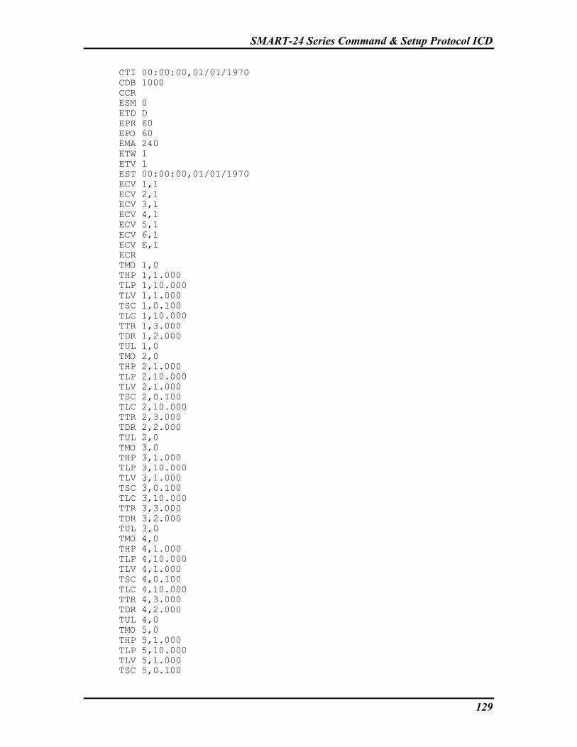
SMART-24 Series Command & Setup Protocol ICD
129
CTI 00:00:00,01/01/1970 CDB 1000 CCR ESM 0 ETD D EPR 60 EPO 60 EMA 240 ETW 1 ETV 1 EST 00:00:00,01/01/1970 ECV 1,1 ECV 2,1 ECV 3,1 ECV 4,1 ECV 5,1 ECV 6,1 ECV E,1 ECR TMO 1,0 THP 1,1.000 TLP 1,10.000 TLV 1,1.000 TSC 1,0.100 TLC 1,10.000 TTR 1,3.000 TDR 1,2.000 TUL 1,0 TMO 2,0 THP 2,1.000 TLP 2,10.000 TLV 2,1.000 TSC 2,0.100 TLC 2,10.000 TTR 2,3.000 TDR 2,2.000 TUL 2,0 TMO 3,0 THP 3,1.000 TLP 3,10.000 TLV 3,1.000 TSC 3,0.100 TLC 3,10.000 TTR 3,3.000 TDR 3,2.000 TUL 3,0 TMO 4,0 THP 4,1.000 TLP 4,10.000 TLV 4,1.000 TSC 4,0.100 TLC 4,10.000 TTR 4,3.000 TDR 4,2.000 TUL 4,0 TMO 5,0 THP 5,1.000 TLP 5,10.000 TLV 5,1.000 TSC 5,0.100

SMART-24 Series Command & Setup Protocol ICD
130
TLC 5,10.000 TTR 5,3.000 TDR 5,2.000 TUL 5,0 TMO 6,0 THP 6,1.000 TLP 6,10.000 TLV 6,1.000 TSC 6,0.100 TLC 6,10.000 TTR 6,3.000 TDR 6,2.000 TUL 6,0 WEN 1,0 WMO 1,0 WST 1,00:00:00,01/01/1970 WDU 1,0 WIN 1,0 WRE 1,0 WEN 2,0 WMO 2,0 WST 2,00:00:00,01/01/1970 WDU 2,0 WIN 2,0 WRE 2,0 WEN 3,0 WMO 3,0 WST 3,00:00:00,01/01/1970 WDU 3,0 WIN 3,0 WRE 3,0 WEN 4,0 WMO 4,0 WST 4,00:00:00,01/01/1970 WDU 4,0 WIN 4,0 WRE 4,0 STD D LTD D USB 1 NPD 0 DMF 80 DMT 0 SFG 1,4.000000 SFG 2,4.000000 SFG 3,4.000000 SFG 4,4.000000 SFG 5,4.000000 SFG 6,4.000000 SSS 1,0.000000 SSS 2,0.000000 SSS 3,0.000000 SSS 4,0.000000 SSS 5,0.000000 SSS 6,0.000000 ANO 0 SFT 1,0 SFT 2,0 SSD 1 URT 50,0D,0,0,0,0,0,0A,0

SMART-24 Series Command & Setup Protocol ICD
131
GPC 0,2,0,0,1,2,3,14,10 DDC 1,1,1 DCL 1A,0,0.000000,1.000000 DCL 2A,0,0.000000,1.000000 DCL 1M,0,0.000000,1.000000 DCL 2M,0,0.000000,1.000000 DCL 3M,0,0.000000,1.000000 DCL 4M,0,0.000000,1.000000 DCL 5M,0,0.000000,1.000000 DCL 6M,0,0.000000,1.000000 EWS 1,0 EWE 1,0 EWI 1,255 EWM 1,0 EWS 2,0 EWE 2,0 EWI 2,255 EWM 2,0 EWS 3,0 EWE 3,0 EWI 3,255 EWM 3,0 EWS 4,0 EWE 4,0 EWI 4,255 EWM 4,0 GOS 0 GPR 1 GFM 1 DFB 0 GET END

SMART-24 Series Command & Setup Protocol ICD
132
This page intentionally left blank.