Embed Size (px)
DESCRIPTION
geotech
Citation preview
GEOTECHNICAL LABS 2014
Njoroge Kagwi Maurice F16/1334/2010 Page 1
LABORATORY DETERMINATION OF PERMIABILITY OF A GRANULAR
SOIL:
1. CONSTANT HEAD PERMEAMETER METHOD
INTRODUCTION
The test is described in BS 1377: part 5.
It covers the determination of the coefficient of permeability for the laminar saturated flow
of water through granular soils such as sand and fine gravel containing no more than 10%
passing the sieve no. 200(0.75mm).
THEORY:PRINCIPLE OF METHOD
The method is based on measuring the volume of water passing through a soil specimen in a
certain time under conditions of constant head, steady state flow, full saturation of soil and
direct proportionality between discharge velocity and hydraulic gradient (Darcy’s law).
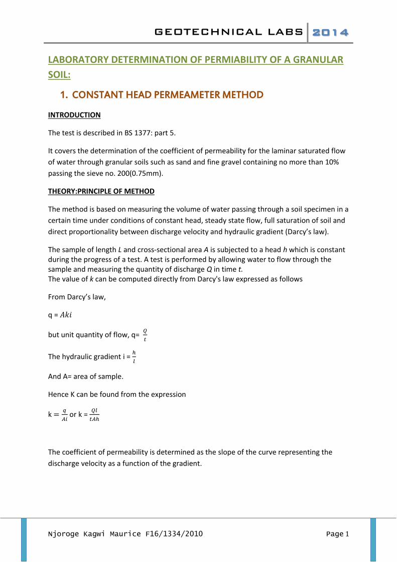
The sample of length L and cross-sectional area A is subjected to a head h which is constant during the progress of a test. A test is performed by allowing water to flow through the sample and measuring the quantity of discharge Q in time t. The value of k can be computed directly from Darcy's law expressed as follows
From Darcy’s law,
q =
but unit quantity of flow, q=
The hydraulic gradient i =
And A= area of sample.
Hence K can be found from the expression
k
or k =
The coefficient of permeability is determined as the slope of the curve representing the
discharge velocity as a function of the gradient.
GEOTECHNICAL LABS 2014
Njoroge Kagwi Maurice F16/1334/2010 Page 2
APPARATUS
Perspex cylinder, glass tube manometers, clean water and sink, de-airing tank and a vacuum
pump, stop watch, balance , measuring cylinders.
SAMPLE : Clean gravel sample of soil
PREPARATION FOR TEST
1. A sieve analysis of the soil to be tested was done.
2. The permeameter connections were checked, gaskets sealed and the cylinder
placed on the base and tightened.
3. The cell was filled with de-aired water and the bottom part of the filter gravel placed
under water to a thickness of about 50mm.
4. The upper filter gravel was also placed to a thickness of 50mm and the upper plate
placed.
5. The four kg weight was placed on the loading shelf and the height of sample, l,
measured.
GEOTECHNICAL LABS 2014
Njoroge Kagwi Maurice F16/1334/2010 Page 3
6. The permeameter inlet was connected to the constant head tank and the
permeameter topped up with de-aired water, letting the air escape through the
bleeder valve.
PROCEDURE
The de-airing tank was operated under high vacuum until it wa s filled with de-aired water.
The constant head tank was filled with deaired water and the vacuum pump disconnected.
The connection to the constant head tank was opened to let water overflow.
The permeameter inlet and outlet were opened and the level of the outlet tubes adjusted to
give mean head loss (∆h).
The mean temperature was measured and recorded.
The stop watch was started and Water from the permeameter outlet collected in a
measuring cylinder. When enough water was collected, the stopwatch was stopped and the
time taken, t, recorded against the volume, v, recorded.
RESULTS
The results of the experiment are as attached.
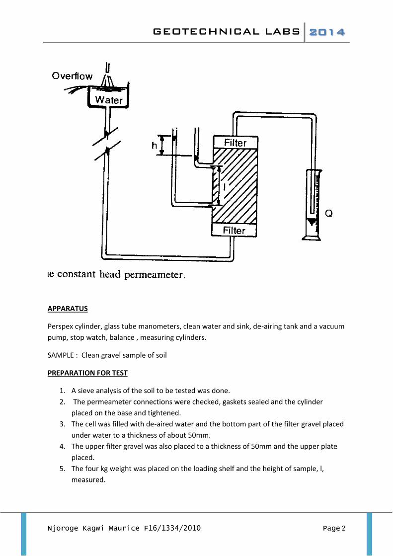
ANALYSIS
Velocity, V=
Dia of cell= 100mm, A=78.54cm2
Gradient, i=
L=350mm
time water discharged, v cm3
Temperature, T 0C
H1 H2 H3 H1-H2 H2-H3 dH gradient velocity
120 30 19 94.3
83.7
65.5
10.6 18.2 -7.6 0.217143 0.003183
240 41 93.7
79.2
59 11.45 20.2 -8.75 0.25 0.002175
360 61 93.2
71.9
42 21.3 29.9 -8.6 0.245714 0.002157
480 81 92.6
63.7
22.8
30.4 40.9 -10.5 0.3 0.002149
GEOTECHNICAL LABS 2014
Njoroge Kagwi Maurice F16/1334/2010 Page 4
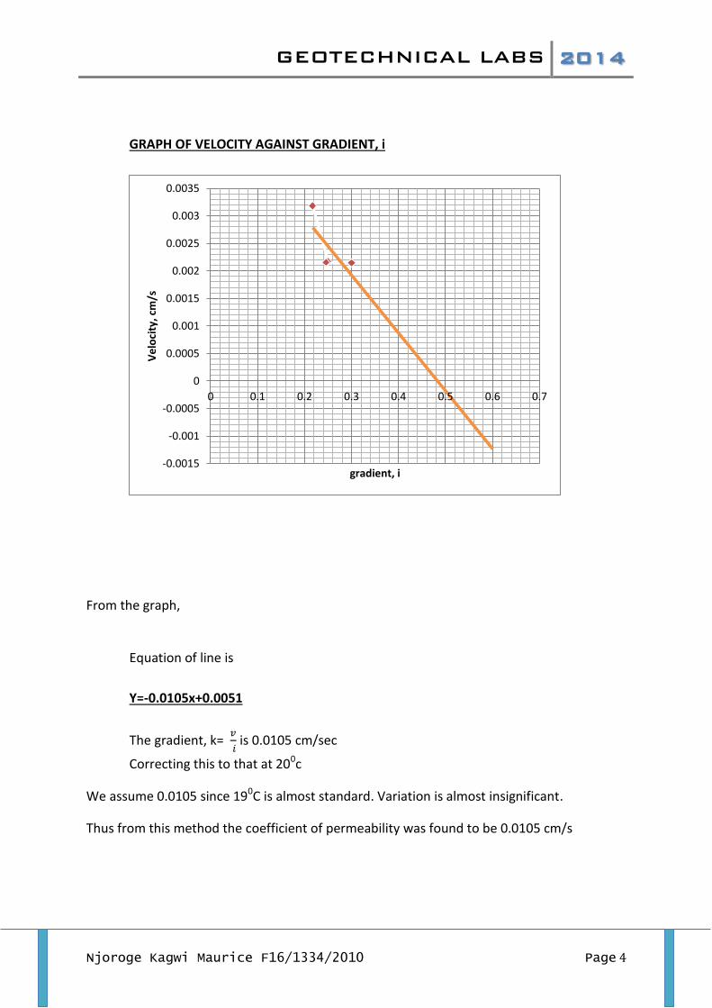
GRAPH OF VELOCITY AGAINST GRADIENT, i
From the graph,
Equation of line is
Y=-0.0105x+0.0051
The gradient, k=
is 0.0105 cm/sec
Correcting this to that at 200c
We assume 0.0105 since 190C is almost standard. Variation is almost insignificant.
Thus from this method the coefficient of permeability was found to be 0.0105 cm/s
-0.0015
-0.001
-0.0005
0
0.0005
0.001
0.0015
0.002
0.0025
0.003
0.0035
0 0.1 0.2 0.3 0.4 0.5 0.6 0.7
Ve
loci
ty, c
m/s
gradient, i
GEOTECHNICAL LABS 2014
Njoroge Kagwi Maurice F16/1334/2010 Page 5
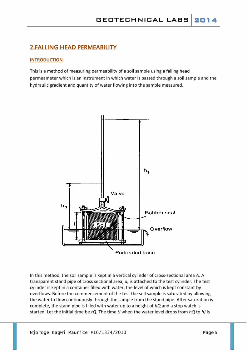
2.FALLING HEAD PERMEABILITY
INTRODUCTION
This is a method of measuring permeability of a soil sample using a falling head
permeameter which is an instrument in which water is passed through a soil sample and the
hydraulic gradient and quantity of water flowing into the sample measured.
In this method, the soil sample is kept in a vertical cylinder of cross-sectional area A. A transparent stand pipe of cross sectional area, a, is attached to the test cylinder. The test cylinder is kept in a container filled with water, the level of which is kept constant by overflows. Before the commencement of the test the soil sample is saturated by allowing the water to flow continuously through the sample from the stand pipe. After saturation is complete, the stand pipe is filled with water up to a height of hQ and a stop watch is started. Let the initial time be tQ. The time tl when the water level drops from hQ to h} is
GEOTECHNICAL LABS 2014
Njoroge Kagwi Maurice F16/1334/2010 Page 6
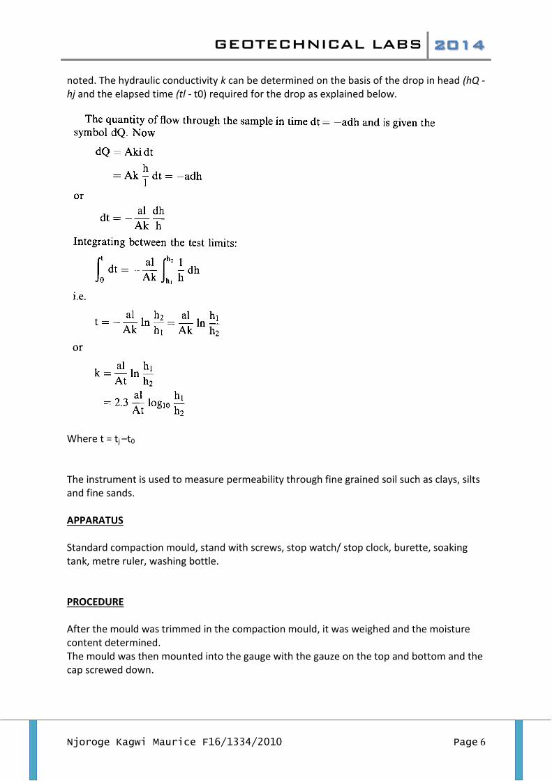
noted. The hydraulic conductivity k can be determined on the basis of the drop in head (hQ - hj and the elapsed time (tl - t0) required for the drop as explained below.
Where t = tj –t0
The instrument is used to measure permeability through fine grained soil such as clays, silts and fine sands. APPARATUS Standard compaction mould, stand with screws, stop watch/ stop clock, burette, soaking tank, metre ruler, washing bottle. PROCEDURE After the mould was trimmed in the compaction mould, it was weighed and the moisture content determined. The mould was then mounted into the gauge with the gauze on the top and bottom and the cap screwed down.
GEOTECHNICAL LABS 2014
Njoroge Kagwi Maurice F16/1334/2010 Page 7
The mould was placed in a soaking tank which was carefully filled with air free water. The air free water was carefully placed in the tank to prevent re aeration by agitation as the tank was filled. The vacuum in the sample drew air from the sample and pulled air free water up into the sample completely saturating it. The saturated sample was then connected up through tubing filled with air-free water to the burette which was also filled air-free water. For the start of test, water is allowed to fall through the sample and times required for it to pass recorded. The burette was refilled with water and the test repeated several times each time being recorded. RESULTS Height of sample = 104mm Diameter 100mm Area of sample = 7850 mm2
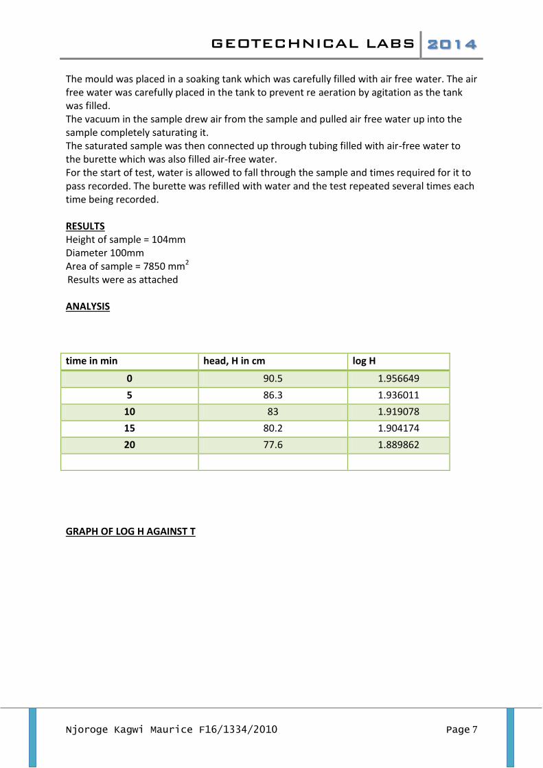
Results were as attached ANALYSIS
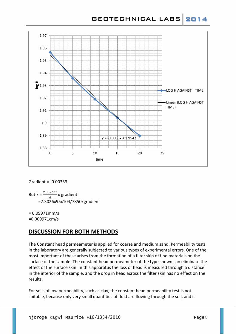
time in min head, H in cm log H
0 90.5 1.956649
5 86.3 1.936011
10 83 1.919078
15 80.2 1.904174
20 77.6 1.889862
GRAPH OF LOG H AGAINST T
GEOTECHNICAL LABS 2014
Njoroge Kagwi Maurice F16/1334/2010 Page 8
Gradient = -0.00333
But k =
x gradient
=2.3026x95x104/7850xgradient = 0.09971mm/s =0.009971cm/s
DISCUSSION FOR BOTH METHODS The Constant head permeameter is applied for coarse and medium sand. Permeability tests in the laboratory are generally subjected to various types of experimental errors. One of the most important of these arises from the formation of a filter skin of fine materials on the surface of the sample. The constant head permeameter of the type shown can eliminate the effect of the surface skin. In this apparatus the loss of head is measured through a distance in the interior of the sample, and the drop in head across the filter skin has no effect on the results. For soils of low permeability, such as clay, the constant head permeability test is not suitable, because only very small quantities of fluid are flowing through the soil, and it
y = -0.0033x + 1.9542
1.88
1.89
1.9
1.91
1.92
1.93
1.94
1.95
1.96
1.97
0 5 10 15 20 25
log
H
time
LOG H AGAINST TIME
Linear (LOG H AGAINSTTIME)
GEOTECHNICAL LABS 2014
Njoroge Kagwi Maurice F16/1334/2010 Page 9
would take very long to collect an appreciable volume of water. For such soils the falling head test is more suitable. It may be remarked that the determination of the hydraulic conductivity of a sample in a laboratory is relatively easy, and with great accuracy, but large errors may occur during sampling of the soil in the field, and perhaps during the transportation from the field to the laboratory. Furthermore, the measured value only applies to that particular sample, having small dimensions. This value may not be representative for the hydraulic conductivity in the field. In particular, if a thin layer of clay has been overlooked, the permeability of the soil for vertical flow may be much smaller than follows from the measurements. On the other hand, if it is not known that a clay layer contains holes, the flow in the field may be much larger than expected on the basis of the permeability test on the clay. It is often advisable to measure the permeability in the field (in situ), measuring the average permeability of a sufficiently large region. In this experiment errors could have resulted from wrong time records, erroneous recording of height of manometer readings and presence of air voids in the soil sample. The coefficient of permeability is used extensively in geotechnical engineering to estimate the soil hydraulic conductivity which is very crucial in the design of foundations, dams, pavements and channels. Hydraulic conductivity is a measure of the ease through which water passes through permeable materials measured in units of velocity. It is inversely proportional to the viscosity of water which is proportional to the temperature hence the need for standard temperature. It also differs with the soil characteristics such as particle sizes and packing as well as extents of void spaces in the soil sample under test. CONCLUSION The coefficient of permeability of the test sample was found to be 0.0105 cm/sec using constant head permeameter method and 0.0099cm/sec using falling head permeameter method.