Embed Size (px)
Citation preview
Indian Journa l of Fibre & Textile Research Vol. 22, December 1997, pp. 318-336
Geosynthetics: Recent developments
G Venkatappa Rao & P K Banerjee
Indian Institute of Technology, Hauz Khas, New Delhi 11 00 16, India
A wide variety of geotextiles and related products available to civil engineers to solve a wide range of problems are' briefly presented along with their functions and poss ible applications. The extensive work being carried out at the Indian Institute of Technology, Delhi, is high lighted. The testing required for hydraulic applications is presented in detail. The work carried out on design of needle-punched fabrics for hydraulic applications is described. A case study on use of edge drains for rural roads is presented. The work in progress on natural fibre geotextiles with jute and coir is included.
Keywords: Co.r, Edge drains, Erosion control, Geotextiles, Hydraulic behaviour, Jute, Natural fibre geotexti les, Polyester, Polypropylene, Roads
I Introduction India is a vast country with widely varying
climatic and terrain conditions. The resulting diverse nature of sub-soil conditions creates a spectrum of problems for the construction engineers. During the last two decades, there has been an increase in demand for construction of civil engineering structures in a variety of topographical conditions. To improve the poor sub-soil conditions in adverse locations, civil engineers have been traditionally depending on conventional raw materials like bricks, cement, steel, etc. But situations arise where there may be non-uniform quality and/or non-availability of desired soils at and around the construction site, leading to high material transportation cost. These and other associated technical limitations of building conventional structures on weak soils lead the civil engineers to search for alternate solutions. One such alternative which has emerged as a popular material/technique in recent years is geotextiles and related products now commonly described as geosynthetics. In the majority of cases, synthetics are produced from man-made fibres; however, they can also be from natural fibres. In fact, geosynthetics are synthesized for use in civil engineering projects to facilitate construction, ensure better performance of the structures and reduce maintenance in the long run. They have
wide applications in almost all geotechnical and hydraulic engineering projects. Typically, such projects include airport and highway pavements, railways, canals, coastal erosion works, dams, embankments, retaining walls, etc.
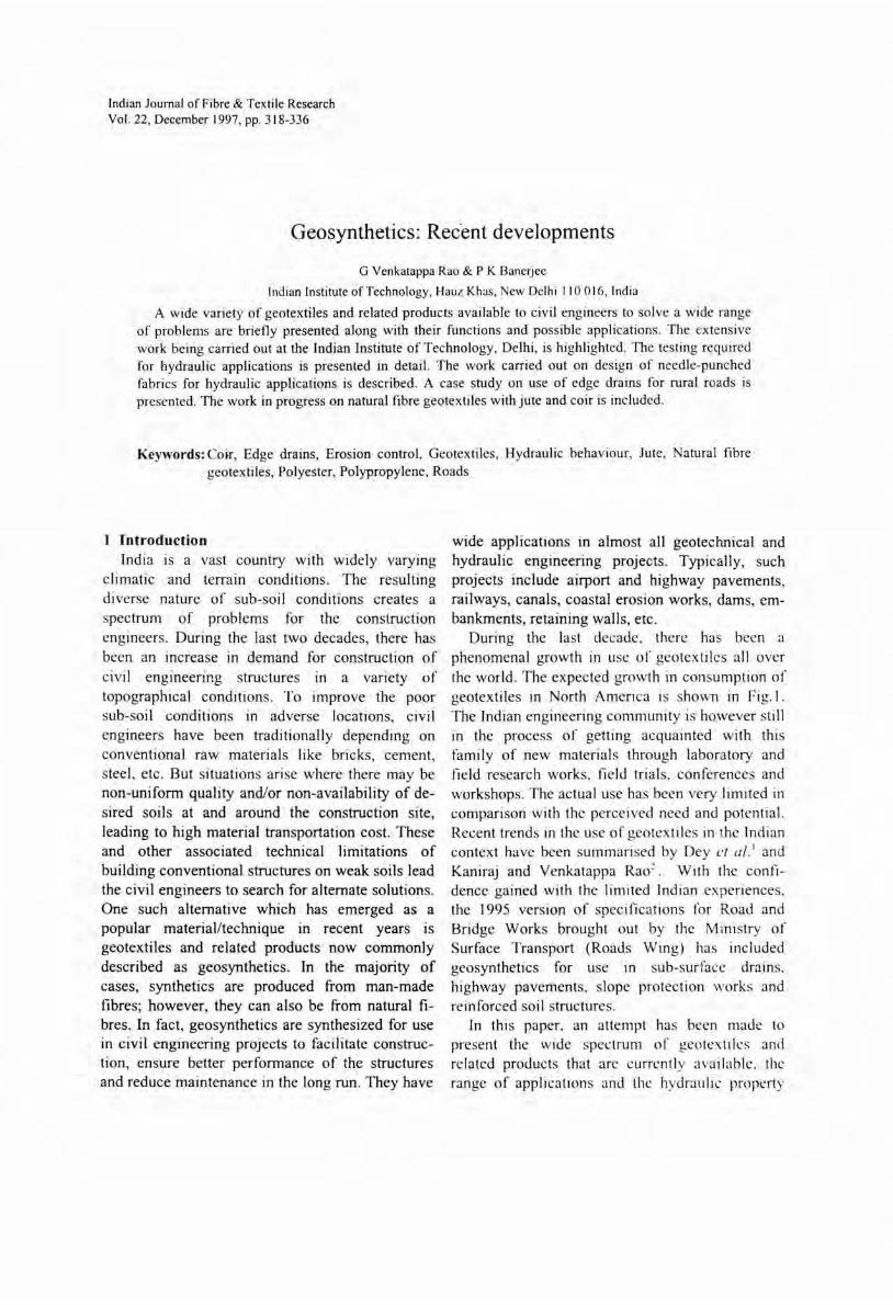
During the last decade, there has been a phenomenal growth in use of geotextiles all over the world. The expected growth in consumption of geotextiles in North America is shown in Fig.l. The Indian engineering community is however still in the process of getting acquainted with thi s family of new materials through laboratory and field research works, field trials, conferences and workshops. The actual use has been very limited in comparison with the perceived need and potential. Recent trends in the use of geotextiles in the Indian context have been summarised by Dey c/ a/.1 and Kaniraj and Venkatappa Rao~ . With the confidence gained with the limited Indian experiences. the 1995 version of spec ifications lor Road and Bridge Works brought out by the Ministry of Surface Transport (Roads Wing) has included geosynthetics for use In sub-surface drains. highway pavements. slope protection works and reinforced soil structures.
In this paper. an attempt has been made to present the wide spec trum of geotextiles and related products that arc currently available. the range of applica tions and the hydralll ic property
RAO & BANERJEE: GEOSYNTHETICS
IIllID 600 9,,ds ~ ErosIon contr~ products
m SptCloli ty products
• upo - synH"Hic doy linprs
1995 1996 1997
Ye ar
Fig. I-IFAI market survey projections (1997)
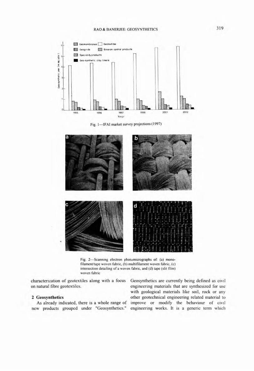
Fig. 2-Scanning electron pholUmicrographs of: (a) monofilament/tape woven fabric, (b) multifilament woven fabric, (c) intersection detailing ofa woven fabric, and (d) tape (s lit film) woven fabric
319
characterization of geotextiles along with a focus on natural fibre geotextiles .
Geosynthetics are currently being defined as civil engineering materials that are synthesized for use with geological materials like soil, rock or any other geotechnical engineering related material to Improve or modify the behaviour of civil engineering works. It is a generic term which
2 Geosynthetics As already indicated, there is a whole range of
new products grouped under "Geosynthetics."
320 INDIAN 1. FIBRE TEXT. RES., DECEMBER 1997
Fig. 3- Scanning electron photomicrographs of: (a) Needlepunched fabric, (b) Needle-punched fabric-closer view, and (c) Thermally-bonded fabric
includes:
• Geotextiles • Geogrids • Geomembranes • Geocomposites • Geonets and other products, geomats,
geomeshes, geowebs, etc.
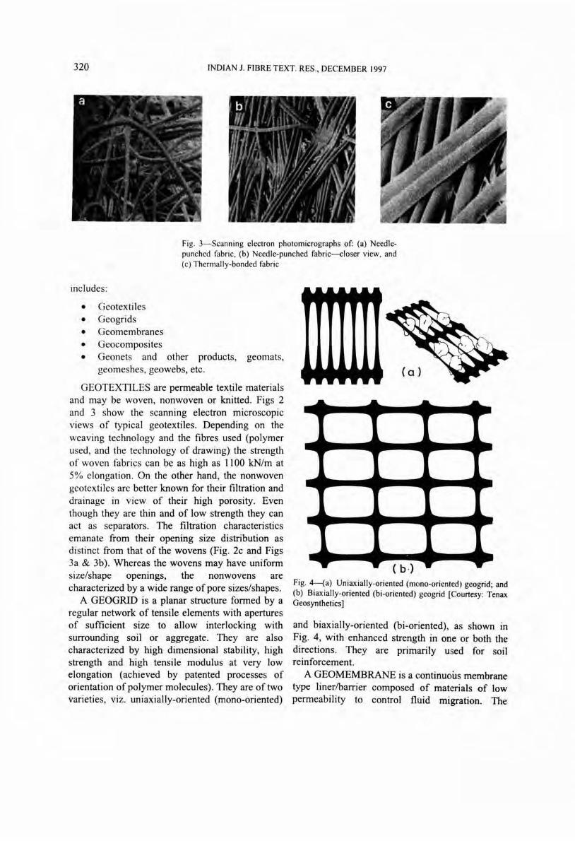
GEOTEXTILES are permeable textile materials and may be woven, nonwoven or knitted. Figs 2 and 3 show the scanning electron microscopic views of typical geotextiles. Depending on the weaving technology and the fibres used (polymer used, and the technology of drawing) the strength of woven fabrics can be as high as 1100 kN/m at 5% elongation. On the other hand, the nonwoven geotextiles are better known for their filtration and drainage in view of their high porosity. Even though they are thin and of low strength they can act as separators. The filtration characteristics emanate from their opening size distribution as distinct from that of the wovens (Fig. 2c and Figs 3a & 3b). Whereas the wovens may have uniform size/shape openings, the nonwovens are characterized by a wide range of pore sizes/shapes.
A GEOGRID is a planar structure formed by a regular network of tensile elements with apertures of sl.)fficient size to allow interlocking with surrounding soil or aggregate. They are also characterized by high dimensional stability, high strength and high tensile modulus at very low elongation (achieved by patented processes of orientation of polymer molecules). They are of two varieties, viz. uniaxially-oriented (mono-oriented)
Fig. 4-(a) Uniaxially-oriented (mono-oriented) geogrid; and (b) Biaxially-oriented (bi-oriented) geogrid [Courtesy: Tenax Geosynthetics]
and biaxially-oriented (bi-oriented), as shown in Fig. 4, with enhanced strength in one or both the directions. They are primarily used for soil reinforcement.
A GEOMEMBRANE is a continuous membrane type linerlbarrier composed of materials of low permeability to control flllid migration. The
RAO & BANERJEE: GEOSYNTHETICS 321
materials could be asphaltic or polymeric or a combination thereof.
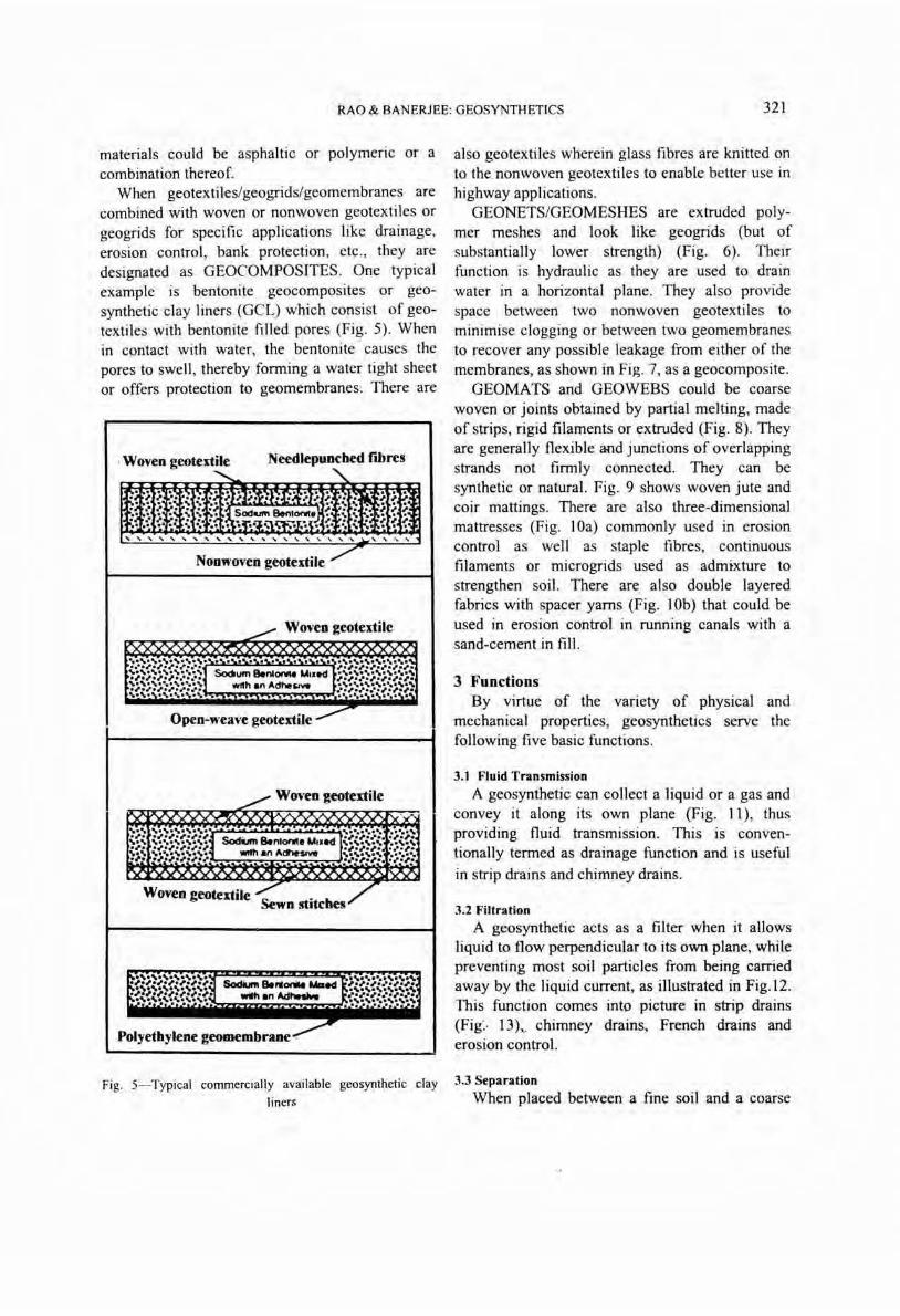
When geotextiles/geogrids/geomembranes are combined with woven or nonwoven geotextiles or geogrids for specific applications like drainage, erosion control, bank protection, etc., they are designated as GEOCOMPOSITES. One typical example is bentonite geocomposites or geosynthetic clay liners (GCL) which consist of geotextiles with bentonite filled pores (Fig. 5). When in contact with water, the bentonite causes the pores to swell , thereby forming a water tight sheet or offers protection to geomembranes. There are
. Woven geotextile Needlepunched fibres
Nonlt'oven geOtextile
~. Woven geotextile xxxxx xxxxxxxxxx
Open-weave geotextile -----
,./ Woven geotextile
x xxx xX' ..... ............... , ......... ....... . ~. .,., ....... " Sodium 8enlOtll'la U'led ."., .... .".,. ..... , .... ,.,.,. ,.,., ... .. ,.,
'b .,.". ....... , WIIh an AdheSIVe
., .... , . .... ~. ..... ............ ,. , .... ,., ....... . ~. .".." .... , ... . . :.-.,." .. .... ,,: x xxx
Woven geotextile /' .. / Sewn stitches
~:;~;~ ... ~ ... ~ ... ~ ... ~;. Sodium 8eNOfW ..... ed ., ....... , ...... ,.,., .... ,.".
~J ................. ~, .... ,., ......... . ".,.,., .... ,.!, wilt! an Ad,.... ... ,.". .... , .... ~}~.~ .. ~ .......... ~-:- •. ..": ....... : ........ ;~,
.~ Polyethylene geomembrane ·
Fig. 5- Typical commercially available geosynthetic clay
liners
also geotextiles wherein glass fibres are knitted on to the. nonwoven geotextiles to enable better use in highway applications.
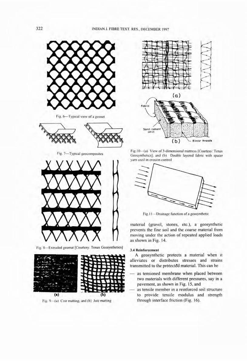
GEONETS/GEOMESHES are extruded polymer meshes and look like geogrids (but of substantially lower strength) (Fig. 6). Their function is hydraulic as they are used to drain water in a horizontal plane. They also provide space between two nonwoven geotextiles to minimise clogging or between two geomembranes to recover any possible leakage from either of the membranes, as shown in Fig. 7, as a geocomposite.
GEOMATS and GEOWEBS could be coarse woven or joints obtained by partial melting, made of strips, rigid filaments or extruded (Fig. 8). They are generally flexible and junctions of overlapping strands not firmly connected. They can be synthetic or natural. Fig. 9 shows woven jute and coir mattings. There are also three-dimensional mattresses (Fig. lOa) commonly used in erosion control as well as staple fibres, continuous filaments or microgrids used as admixture to strengthen soil. There are. also double layered fabrics with spacer yams (Fig. lOb) that could be used in erosion control in running canals with a sand-cement in fill.
3 Functions By virtue of the variety of physical and
mechanical properties, geosynthetics serve the following five basic functions .
3.1 Fluid Transmission
A geosynthetic can collect a liquid or a gas and convey it along its own plane (Fig. 11), thus providing fluid transmission. This is conventionally termed as drainage function and is useful
in strip drains and chimney drains.
3.2 Filtration
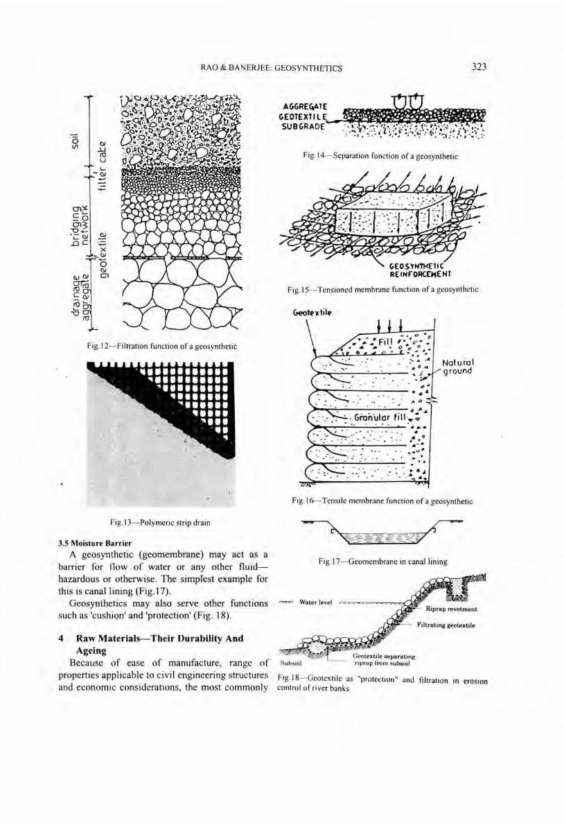
A geosynthetic acts as a filter when it allows liquid to flow perpendicular to its own plane, while preventing most soil particles from being carried away by the liquid current, as illustrated in Fig.12. This function comes into picture in strip drains (Fig:· D) •. chimney drains, French drains and erosion control.
3.3 Separation
When placed between a fine soil and a coarse
322 INDIAN 1. FIBRE TEXT. RES ., DECEMBER 1997
Fig. 6- Typi cal view of a geonet
Fig. 7-Typical geocomposites
Fig. 8-Extruded geomat [Courtesy: Tenax Geosynthetics)
!~ • , ..... :1l
-,. ~
.~ r"' "Ii :- po
... ~
... ~ ."11 III!
*' ;. ~ ~ -
(a) (b)
Fig. 9- (a) Coir matting; and (b) Jute matting
-= ---,
:::i t-- -j \. t-")
-I.. 1 r--'-f / ./.
L 7
.1.
;:;;;;
l. (
J 1/ :.:' .L
Fi g. IO- (a) View of 3-dimensional mattress [Courtesy: Tenax Geosyntheti cs]; and (b) Doubl e layered fa bric with spacer yarn used in erosion control
-----------------Fig. I I- Drainage fun cti on of a geosynthetic
material (gravel, stones, etc.), a geosynthetic prevents the fine soil and the coarse material from moving under the action of repeated applied loads as shown in Fig. 14.
3.4 Reinforcement
A geosynthetic protects a material when it alleviates or distributes stresses and strains transmitted to the protectc!d material. This can be
as tensioned membrane when placed between two materials with different pressures, say in a pavement, as shown in Fig. 15 , and as tensile member in a reinforced soil structure to provide tensile modulus and strength through interface fricti on (Fig. 16).
RAO & BANERJEE: GEOSYNTHETICS 323
01 ..u ro v L...
-01
Fig. 12- Filtration function of a geosynthetit
Fig. 13- Polymeric strip drain
3.5 Moisture Barrier
A geosynthetic (geomembrane) may act as a barrier for flow of water or any other fluidhazardous or otherwise. The simpTest example for this is canal lining (Fig.I7).
Geosynthetics may also serve other functions such as 'cushion' and 'protection' (Fig. 18).
4 Raw Materials--Their Durability And Ageing
Because of ease of manufacture, range of properties applicable to civil engineering structures and economic considerations, the most commonly
Fig. 14- Separation function of a geosynthetic
Fig. IS- Tensioned membrane function of a geosynthetic
GEootf.')( t i 1(>
_.,0 • ., ,. P'. 0- 0
~~~~~~~~~~~.: ~ . • :'- A ....
. • 0 4
. " . ~
-." . . " . . .
... •
• 0 . . ~~~--~--------~- .',.",-. . .
: : ; . ~ . .,
Natural ground
Fig.16- Tensile membrane function of a geosynthetic
Fig.17- Geomembrane in canal lining
Water level
Filtrating geotextile
Subsoil
Fig.18- Geotextile as "protection" and filtration in erosion control of river banks
324 INDIAN J. FIBRE TEXT. RES., DECEMBER 1997
used polymers in the manufacture of geosynthetics are:
Polyester fibres have high modulus, low susceptibility to creep, and no vanatIon in mechanical properties at temperatures near 180-200°C. They are also inert in sea water and weak acids.
• Polypropylene (Polyolefin) • Polyethylene (Polyolefin) • Polyester • Polyvinyl chloride • Elastomers.
Polyolefins have proven to be one of the most attractive of the fibre forming polymers owing to their low cost and inert nature . A large proportion of geosynthetics today In the market IS
manufactured from polypropylene. However, polypropylene fibres are highly susceptible to creep and UV degradation .
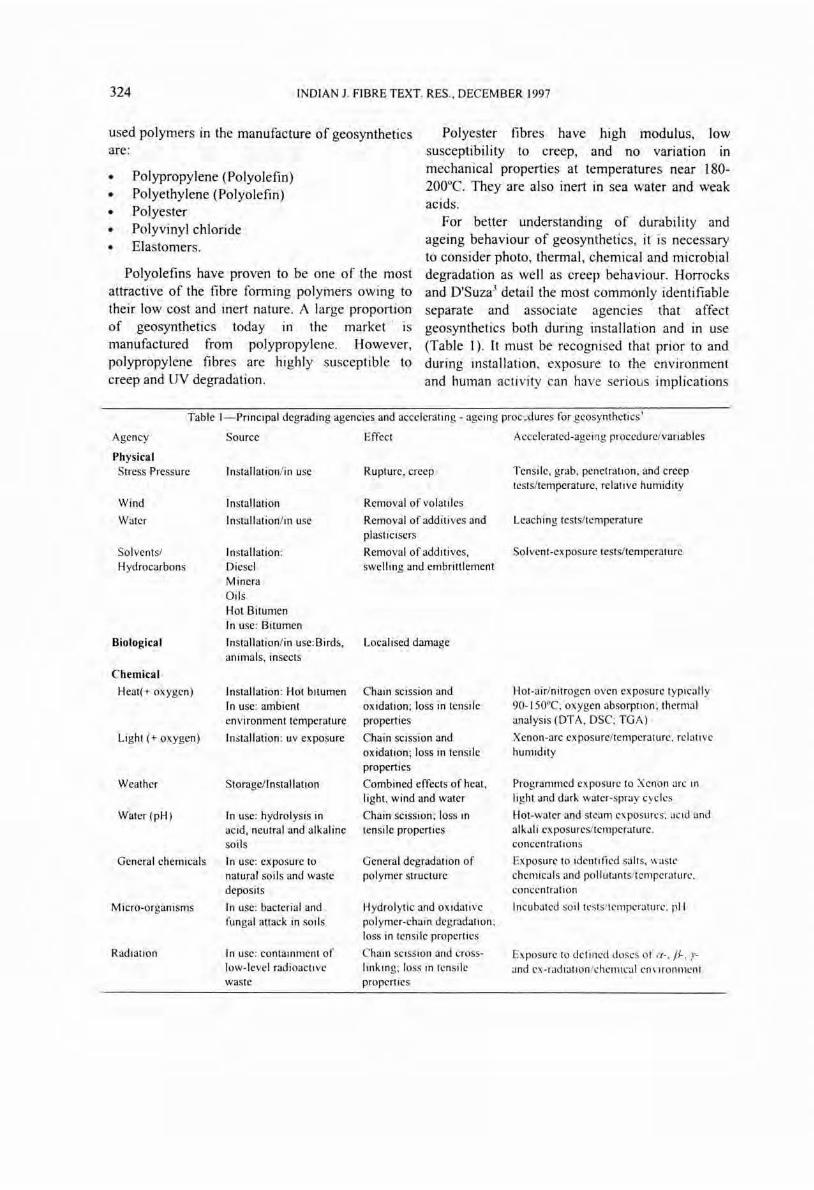
For better understanding of durability and ageing behaviour of geosynthetics, it is necessary to consider photo, thermal, chemical and microbial degradation as well as creep behaviour. Horrocks and O'Suza3 detail the most commonly identifiable separate and associate agencies that affect geosynthetics both during installation and in use (Table 1). It must be recognised that prior to and during installation, exposure to the environment and human activity can have serious implications
Table I- Principal degrading agencies and accelerating - ageing proc;;dures for geosynthetics'
Agency
Physical Stress Pressure
Wind
Water
Solvents/ Hydrocarbons
Biological
Chemical
Heat{+ oxygen)
Light (+ oxygen)
Weather
Water (pH)
General chemicals
Micro-organisms
Radiation
Source
Installationli n use
Installation
In stallationli n use
Installation : Diesel Minera Oils Hot Bitumen In use: Bitumen
Installation/in use:Bird~,
animals, insects
Installation : Hot bitumen In use: ambient environment temperature
Installation: uv exposure
Storage/Installation
In use: hydrolysis in acid, neutral and alkaline soils
In use: exposure to natural soils and waste deposits
In use: bacterial and fungal attack in soils
In use: containment of low-level radioacti ve waste
Effect
Rupture, creep
Removal of volatiles
Accelerated-ageing procedureivariables
Tensile, grab, penetration, and creep tests/temperature, relative humidity
Removal of additives and Leaching tests/temperature plasticisers
Removal of additives, Solvent-exposure tests/temperature swelling and embrittlement
Localised damage
Chain scission and oxidation; loss in tensile properties
Chain scission and oxidation; loss in tensile properties
Combined effects of heat, light, wind and water
Chain scission; loss in tensi Ie properties
General degradation of pol ymer structure
Hydrolytic and oxidativc polymer-chain degradation ; loss in tensile properties
Chain scission and crosslinking; loss in tensile properties
Hot-air/nitrogen oven exposure typicall y 90-ISO°C; oxygen absorption; thermal analysis (DTA, DSC; TGA)
Xenon-arc exposure/temperature, rel ati ve humidity
Programmed exposure to Xenon arc in light and dark water-spray cycles
Hot-water and sh:am ex posures: acid and alkali exposures/temperature . concentrations
Ex posure to identified salts, waste chemicals and pollutants/temperature. concentration
Incubated so il tests/temperatu re. pH
Exposure to defined doses of a-, /1-. rand ex-radiat ion/chemical ell\'ironment
RAO & BANERJEE: GEOSYNTHETICS 325
with regard to the life. Venkatappa Rao et al.4 and Baja/ provide a detailed review of the various aspects concerning durability. Baja/ summarises that most polymers are susceptible to direct sunlight degradation (UV light and heat combination) which can cause chain scission or crosslinking in the polymer, leading to the polymer enbrittlement and failure. Polypropylene is more susceptible to UV degradation. Carbon black and antioxidants are therefore added to melt prior to fibre extrusion to delay the onset of degradation. By these processes, geosynthetics with as much as 120 years service life are available in the market.
Furthermore, resistance to permanent deformation (creep) under long-term loading must be assessed. In this context, polyester geotextiles perform better.
For predicting the actual life time of a buried geotextile material, it is necessary to know the nature of the surrounding soil, site specific pore water, the ambient temperature and the stress.
5 Testing and Evaluation In order to successfully design and con.struct
with geosynthetics, it is essential to test and evaluate them for a given application to serve the specific function. In addition, the properties are required for quality control, both during production and installation.
5.1 Property Grouping
The desired properties can be grouped as follows:
Basic Physical Pr~perties • constituent and method of manufacture • mass per unit area • thickness • openmg size • roll width, roll length
Mechanical Properties • tensile strength • tensile modulus • interface friction
• fatigue resistance
• creep resistance
• seam strength
Hydraulic Properties • permittivity • transmissivity
ConstructabilitylSurvivability Properties • strength and stiffness
• puncture resistance
• tear resistance
• cutting resistance
• inflammability
• temperature stability
• ultra-violet stability
• absorption
Durability (Longevity) • abrasion resistance • temperature stability • chemical stability • bioiogical stability • wetting and drying stability.
Extensive work has been carried on the above at lIT-Delhi. A summary of the work carried out has been recently reported by Venkatappa Ra06
• The following presents the highlights concerning the hydraulic behaviour.
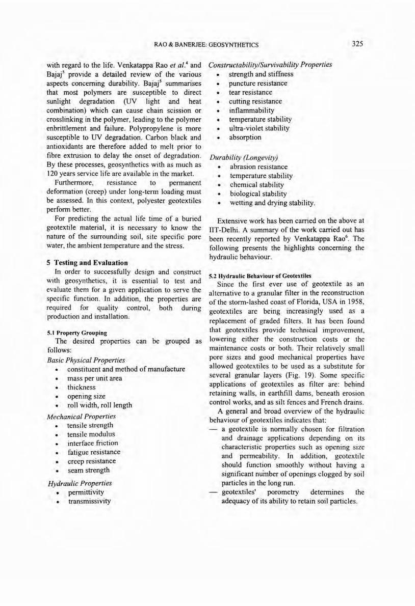
5.2 Hydraulic Behaviour of Geotextiles Since the first ever use of geotextile as an
alternative to a granular filter in the reconstruction of the storm-lashed coast of Florida, USA in 1958, geotextiles are being increasingly used as a replacement of graded filters. It has been found that geotextiles provide technical improvement, lowering either the construction costs or the maintenance costs or both. Their relatively small pore sizes and good mechanical properties have allowed geotextiles to be used as a substitute for several granular layers (Fig. 19). Some specific applications of geotexti1es as filter are: behind retaining walls, in earthfill dams, beneath erosion control works, and as silt fences and French drains.
A general and broad overview of the hydraulic behaviour of geotextiles indicates that:
a geotextile is normally chosen for filtration and drainage applications depending on its characteristic properties such as opening size and permeability. In addition, geotextile should function smoothly without having a significant number of openings clogged by soil particles in the long run. geotextiles' porometry determines the adequacy of its ability to retain soil particles.
326 INDIAN J. FIBRE TEXT. RES., DECEMBER 1997
S.2.1 Hydrodynamic Sieving Test
Different experimental methods are available for the evaluation of geotextiles' pore sizes. A well defined simple method of short duration that
Primary armour
- Secondary armour ,",d'!:lJI;lil"l'".:~.- C.oarse 'Jlter
.' ./~ .. - Fine filter
Graded fi Iter
- Pri mary armour
Sutatituting for fine granular layer
Substituting for fin. and coarse granular Ia-,.rs
Geotext i Ie
Bose soil
Primary armour
Primary armoU'
~~_~'-"""- Geot •• tile
Bose soil
Substituting lor fin. and coors. granular toyers and s.condary armour
Fig.19-Graded aggregate filter and geotextile filter systems under rip-rap slope protection
allows the determination of the porometry of all types of geotextiles is preferred which simulates the field condition and presents reproducible results. Though several methods of pore size determination exist, no procedure has yet been identified as a satisfactory standard in yielding, a correct value.
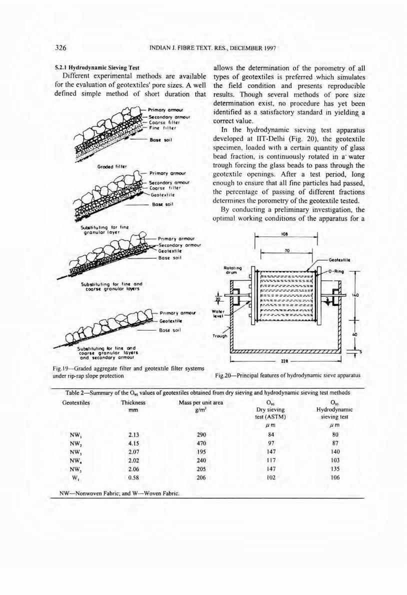
In the hydrodynamic sieving test apparatus developed at lIT-Delhi (Fig. 20), the geotextile specimen, loaded with a certain quantity of glass bead fraction, is continuously rotated in a' water trough forcing the glass beads to pass through the geotextile openings. After a test period, long enough to ensure that all fine particles had passed, the percentage of passing of different fractions determ ines the porometry of the geotextile tested.
By conducting a preliminary investigation, the optimal working conditions of the apparatus for a
Woter icvel
Trough
I 10&
I ~. ____ ~7~0 ____ ~
G.otulit.
O-Ring
~::.:::.~-:~~~~~~:.~:~~ r--:==.:--::-~----... ~::o
~~-~-:-~~~~~=~~~~~i F'~ ... ~=-=-:::--,.. -:.:---,.~
~~=:=:~:::~::::~ F ==.:--~-:.: =-------:..-:.~
22& ------I
Fig.20-Principal features of hydrodynamic sieve apparatus
Table 2-Summary of the 0 95 values of geotextiles obtained from dry sieving and hydrodynamic sieving test methods
Geotextiles Thickness Mass per unit area 0 95 0 95
mm g/m2 Dry sieving Hydrodynamic test (ASTM) sieving test
Jim Jim
NW I 2,13 290 84 80
NW2 4.15 470 97 87
NWJ 2.07 195 147 140
NW. 2.02 240 117 103
NWs 2.06 205 147 135
WI 0.58 206 \02 106
NW-Nonwoven Fabric; and W-Woven Fabric.
RAO & BANERJEE: GEOSYNTHETICS 327
fractioned spherical glass beads of 50 g were selected. These are: (i) a cycle speed of 20 rpm, and (ii) a test duration of 1500 cycles.
Table 2 presents the 0 95 values with dry sieve test as compared to hydrodynamic sieve test which is attributed to the non-renewal of the geotextile
Porou slon.
Silicon. gr'OSf
Inl.t
~r:z:ca::d -
Silicon. gr.Gn
(j.otutil. ~rtorol.d
pial.
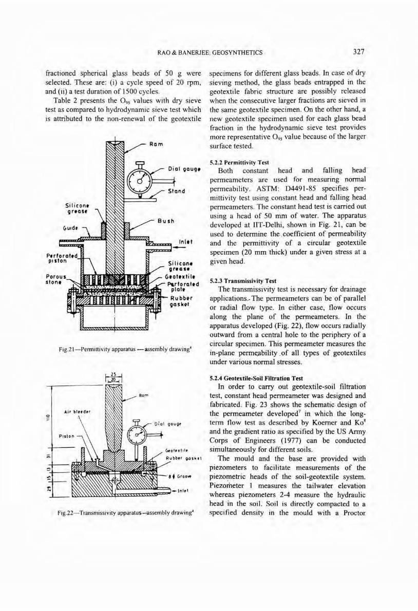
Fig.2 1- Permittivity apparatus ~assembly drawing4
--r-------
o
!:!-+---
~ I~I
"'oluld.
Rubb.r ~QSk.1
a. (jroow
Fig.22- Transmissivity apparatus-lassembly drawing'
specimens for different glass beads . In case of dry sieving method, the glass beads entrapped in the geotextile fabric structure are possibly released when the consecutive larger fractions are sieved in the same geotextile specimen. On the other hand, a new geotextile specimen used for each glass bead fraction in the hydrodynamic sieve test provides more representative 0 95 value because of the larger surface tested.
5.2.2 Permittivity Test Both constant head and falling head
permeameters are used for measuring normal permeability. ASTM : D4491-85 specifies permittivity test using constant head and falling head permeameters. The constant head test is carried out using a head of 50 mm of water. The apparatus developed at liT-Delhi, shown in Fig. 21, can be used to determine the . coefficient of permeability and the permittivity of a circular geotextile specimen (20 mm thick) under a given stress at a given head.
5.2.3 Transmissivity Test
The transmissivity test is necessary for drainage applications .. The permeameters can be of parallel or radial flow type. In either case, flow occurs along the plane of the permeameters. In the apparatus developed (Fig. 22), flow occurs radially outward from a central hole to the periphery of a circular specimen. This permeameter measures the in-plane perme.ability .of all types of geotextiles under various normal stresses.
5.2.4 Geotextile-Soil Filtration Test
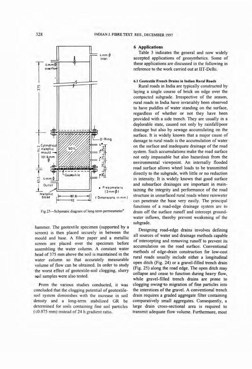
In order to carry out geotextile-soil filtration test, constant head permeameter was designed and fabricated. Fig. 23 shows the schematic design of the permeameter developed7 in which the longterm flow test as described by Koerner and K0 8
and the gradient ratio as specified by the US Army Corps of Engineers (1977) can be conducted simultaneously for different soils.
The mould and the base are provided with piezometers to facilitate measurements of the piezol!letric heads of the soil-geotextile system. Piezometer 1 measures the tailwater elevation whereas piezometers 2-4 measure the hydraulic head in the soil. Soil is directly compacted to a specified density in the mould with a Proctor
328 INDIAN 1. FIBRE TEXT. RES., DECEMBER 1997
J
T Il~ i.mmA. ~I 'Y ..,
lL i.mm¢> Inlfl
O-Ring
L outt::n============:::J Mflellic L_-101 6~1
be se I r' ( Dimfnsions In mm ) .• 112
Fig.23- Sch.ematic diagram of long-term permeameter9
hammer. The geotextile specimen (supported by a screen) is then placed securely in between the mould and base. A filter paper and a metallic screen are placed over the specimen before assembling the water column. A constant ~ater head of 375 mm above the soil is maintained in the water column so that accurately measurable volume of flow can be obtained. In order to study the worst effect of geotextile-soil clogging, slurry scil samples were also tested.
From the various studies conducted, it was concluded that the clogging potential of geotextilesoil system diminishes with the increase in soil density and a long-term stabilized GR be determined for soils containing fine soil particles (:<:;0.075 mm) instead of 24 h gradient ratio.
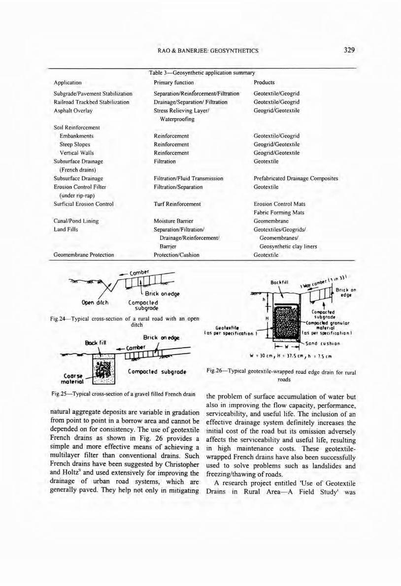
6 Applications Table 3 indicates the general and now widely
accepted applications of geosynthetics. Some of these applications are discussed in the following in reference to the work carried out at lIT-Delhi.
6.1 Geotextile French Drains in Indian Rural Roads
Rural roads in India are typically constructed by laying a single course of brick on edge over the compacted subgrade. Irrespective of the season, rural roads in India have invariably been observed to have puddles of water standing on the surface, regardless of whether or not they have been provided with a side trench. They are usually in a deplorable state, caused not only by rainfall/poor drainage but also by sewage accumulating on the surface. It is widely known that a major cause of damage to rural roads is the accumulation of water on the surface and inadequate drainage of the road system. Such accumulations make the road surface not only impassable but also hazardous from the environmental viewpoint. An internally flooded road surface allows wheel loads to be transmitted directly to the subgrade, with little or no reduction in intensity. It is widely known that good surface and subsurface drainages are important in maintaining the integrity and performance of the road structure in unsurfaced rural roads where rainwater can penetrate the base very easily. The principal functions of a road-edge drainage system are to drain off the surface runoff and intercept groundwater inflows, thereby prevent weakening of the subgrade.
Designing road-edge drains involves defining all sources of water and drainage methods capable of intercepting and removing runoff to prevent its accumulation on the road surface. Conventional methods of edge-drain construction for low-cost rural roads usually include either a longitudinal open ditch (Fig. 24) or a gravel-filled trench drain (Fig. 25) along the road edge. The open ditch may collapse and cease to function during heavy flow, while gravel-filled trench drains are prone to clogging owing-'to migration of fine particles into . the interstices of the gravel. A conT~entional trench drain requires a graded aggregate filter containing comparatively small aggregates. Consequently, a large drain cross-sectional area is required to transmit adequate flow volume. Furthermore, most
RAO & BANERJEE: GEOSYNTHETICS 329
Table 3-Geosynthetic application summary
Application
Subgrade/Pavement Stabilization
Railroad Trackbed Stabili zation
Asphalt Overlay
Primary function
Separation/Rein(orcementlFiltration
Drainage/Separation/ Filtration
Stress Relieving Layer/
Products
Geotex ti le/Geogrid
Geotexti le/Geogrid
Geogrid/Geotextile
Soil Reinforcement
Embankments
Steep Slopes
Vertical Walls
Waterproofing
Reinforcement
Reinforcement
Reinforcement
Filtration
Geotextile/Geogrid
Geogrid/Geotexti Ie
Geogrid/Geotexti Ie
Geotextile Subsurface Drainage
(French drains)
Subsurface Drainage
Erosion Control Filter
(under rip-rap)
Surficial Erosion Control
Filtration/Fluid Transmission
Filtration/Separation
Prefabricated Drainage Composites
Geotextile
Turf Reinforcement
Canal/Pond Lining
Land Fills
Geomembrane Protection
Moisture Barrier
SeparationlFiltration/
Drainage/Reinforcement!
Barrier
Protection/Cushion
Erosion Control Mats
Fabric Forming Mats
Geomembrane
Geotextiles/Geogridsl
Geomembranes/
Geosynthetic clay liners
Geotextile
<>p.n ditch (ompoctl'd subgrodl'
Fig.24-Typical cross-section of a rural road with an openditch
Brick on.clge
(ornpocttd subgrodt
Fig.25-Typical cross-section of a gravel filled French drain
natural aggregate deposits are variable in gradation from point to point in a borrow area and cannot be depended on for consistency. The use of geotextile French drains as shown in Fig. 26 provides a simple and more effective means of achieving a multilayer filter than conventional drains. Such French drains have been suggested by Christopher and Holtz9 and used extensively for improving the drainage of urban road systems, which are generally paved. They help not only in mitigating
Backfill
(jllotllxtil. los PIPT splcificotion I
, (ompochrd
Brick on IIdg.
s ub grod~ (ompoc .. d gronu lor
mot.rlol los PlPr sppcificolion I
W:)Ocm,H : )7.,)cm,h :7.')cm
Fig.26-Typical geotextile-wrapped road edge drain for rural
roads
the problem of surface accumulation of water but also in improving the flow capacity, performance, serviceability, and useful life. The inclusion of an effective drainage system definitely increases the initial cost of the road but its omission adversely affects the serviceability and useful life, resulting in high maintenance costs. These geotextilewrapped French drains have also been successfully used to solve problems such as landslides and freezing/thawing of roads.
A research project entitled 'Use of Geotextile Drains in Rural Area-A Field Study' was
330 INDIAN J. FIBRE TEXT. RES., DECEMBER 1997
undertaken at the Indian Institute of Technology, Delhi, in collaboration with the Centre for Agrarian Research, Training & Education (CARTE), Ghaziabad, India. The project was sponsored by the Department of Science and Technology, Government of India. This project is perhaps the first attempt of its kind aimed at improving the performance of rural roads. The area chosen for the study was located in the IndoGangetic alluvial zone, where the common soil is silt. In these areas, 80% of the annual rainfall occurs in the three monsoon months and is of high intensity and short duration .
The presence of a geotextile filter leads to the development of a natural filter and enables larger and more permeable aggregates within the drain to be used. It prevents contamination of the drain core and eliminates the' risk of road detritus and backfill soil entering the drain core. A geotextile filter needs to satisfy the following two conflicting requirements simultaneously: (i) to prevent significant particle movement from the adjacent soil into the drainage, and (ii) to provide sufficient hydraulic conductivity to permit the free flow of water into the drain .
6.1.1 Field Trial
Harsaon, a village on the outskirts of Ghaziabad township and nearly 30 km from Delhi on the National Highway No.24, was selected for the trial. The general condition of the village road in May 1990 was poor when longitudinal open ditches ceased to function owing to clogging. A stretch nearly 100 m long was selected near one end of the village, where it was possible to discharge into a nearby pond. There are houses on both sides of this road, and household sewage is directly led into the road-edge drain. The drain is designed for a gradient of 1: 120. The effluent from the neighbourhood would first be collected in Manhole-l and then led to the geotextile-wrapped drain. A catchpit is provided at a sharp turn for maintenance and inspection of the drain. Manhole-2 is provided at the end of the drain, whence the effluent is discharged to the existing pond. The outfall level is kept higher than the maximum expected wafer level of the pond to avoid back flow. The in-situ soil is mainly alluvial silt with fine sand. The physical properties of the soil are:
sand 42%, silt 56%, clay 2%, liquid limit 26% and plastic limit 18%.
Suitable geotextiles were selected by examining their filter and permeability characteristics as specified by filter criteria of the US Forest Service and Transportation Agencies . A conventional graded filter would require to be graded over the range of 0.6-6.0 mm for this site. The maximum pore size, 0 95 , of the fabric for this type of soil is
130 J1rrI . Two types of needle-punched polypropylene-fibre geotextiles were chosen 10. Flow rates and the coefficient of normal permeability were
. also determined. For the clogging potential of the geQtextiles, gradient ratios were determined by using 60% sand and 40% fine soils. The geotextiles used were having a mass per unit area of 205 and 220 g/m2
.
Construction was carried out as per Christopher and Holtz9
. Household waste is directly led into Manhole-I, which is required to be cleaned periodically. Geotextile and metallic screens were provided at the beginning of the drain to prevent solid wastes from being carried into the geotextile drain. A perforated steel sheet was also provided in the manhole to prevent contamination of the drain core . The system was found to be working satisfactorily. The details of the study are reported by Venkatappa Rao et al. elsewhere " .
6.2 Pavements
Ghosal and Som l 2 reported the first major use of a nonwoven fabric in a heavy duty yard in Haldia . It has been found to decrease the pavement thickness to the extent of 30%.
Placement of geotextileslgeogrids at the interface between the subgrade and the sub-base course has been shown to improve the behaviour of pavements under cyclic loading, both in terms of permanent deformation (rutting) and resilient modulus. Also, use of geogrids in a flexible overlay has been found to improve the overall behaviour. A summary of these works is reported by Venkatappa Raoo. Nonwoven geotextiles and bi-oriented geogrids have been successfully utilised in Maharashtra (1997) in the State Highways by the P.W.D. for strengthening the road pavements in black cotton soil.
RAO & BANERJEE: GEOSYNTHETICS 331
Type ofGS
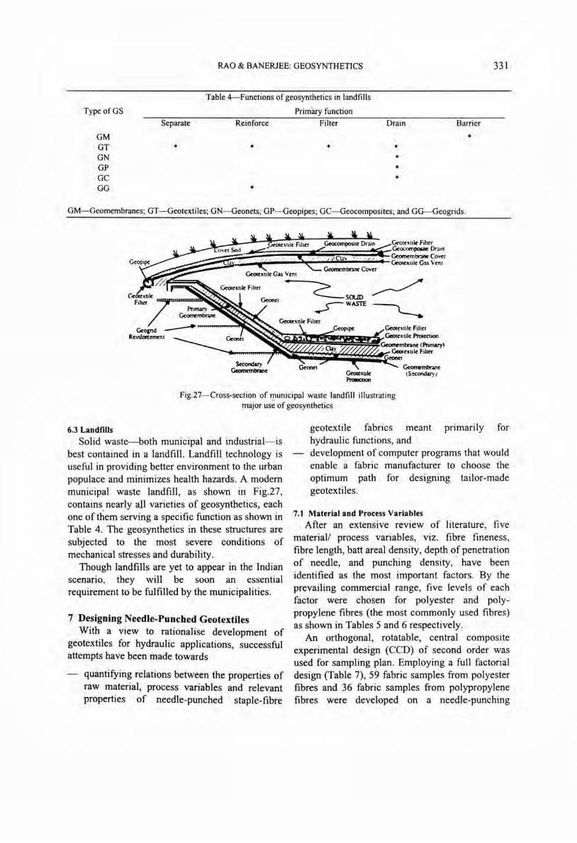
Table 4-Functions of geosynthetics in landfills
Primary function
GM GT GN GP GC GG
Separate
*
Reinforce Filter
* *
*
. Drain Barrier
* * * * *
GM-Geomembranes; GT -Geotextiles; GN-Geonets; GP-Geopipes; GC-Geocomposites; and GG-Geogrids.
Gecuxule Proecnon
Fig.27-Cross-section of f!1unicipal waste landfill illustrating major use of geosynthetics
6.3 Landfills Solid waste-both municipal and industrial- is
best contained in a landfill . Landfill technology is useful in providing better environment to the urban populace and minimizes health hazards. A modern municipal waste landfill , as shown in Fig.27, contains, nearly all varieties of geosynthetics, each one of them serving a specific function as shown in Table 4. The geosynthetics in these structures are subjected to the most severe conditions of mechanical stresses and durability.
Though landfills are yet to appear in the Indian scenario, they will be soon an essential requirement to be fulfilled by the municipalities.
7 Designing Needle-Punched Geotextiles With a view to rationalise development of
geotextiles for hydraulic applications, successful attempts have been made towards
quantifying relations between the properties of raw material, process variables and relevant properties of needle-punched staple-fibre
geotextile fabrics meant primarily for hydraulic functions, and development of computer programs that would enable a fabric manufacturer to choose the optimum path for designing tailor-made geotextiles.
7.1 Material and Process Variables
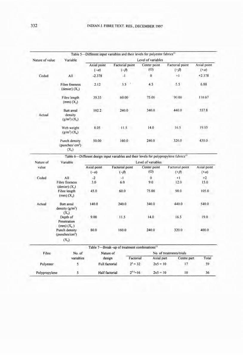
After an extensive review of literature, five material! process variables, viz. fibre fineness , fibre length, batt areal density, depth of penetration of needle, and punching density, · have been identified as the most important factors . By the prevailing commercial range, five levels of each factor were chosen for polyester and polypropylene fibres (the most commonly used fibres) as shown in Tables 5 and 6 respectively.
An orthogonal, rotatable, central composite experimental design (CCD) of second order was used for sampling plan. Employing a full factorial design (Table 7), 59 fabric samples from polyester fibres and 36 fabric samples from polypropylene fibres were developed on a needle-punching
332 INDIAN J. FIBRE TEXT. RES., DECEMBER 1997
Table 5-Different input variables and their levels for polyester fabrics ')
Nature of value Variable Level of variables
Axial point Factorial point Center point Factorial point Axial point
(-a) (-fJ) (0) (+fJ) (+a)
Coded All -2 .378 -I 0 + 1 +2.378
Fibre fineness 2.12 3.5 I 4.5 5.5 6.88 (denier) (XI)
Fibre length 39.33 60.00 75 .00 90.00 110.67 (mm) (X2)
Batt areal 102.2 240.0 340.0 440.0 557.8
Actual density (g/m2) (X))
Web weight 8.05 11.5 14.0 16.5 19.95 (g/m2) (X.)
Punch density 50.00 160.0 240.0 320.0 4300 (punches! cm2
)
(Xs)
Table 6--Different design input variables and their levels for polypropylene fabrics ll
Nature of Variable Level of variables
value Axial point Factorial point Center point Factorial point Axial point
(-a) (-fJ) (0) (+fJ) (+a)
Coded All -2 -I 0 + 1 +2 Fibre fineness 3.0 6.0 9.0 12.0 15 .0 (denier) (XI) Fibre length 45 .0 60.0 75 .00 90.0 105 .0 (mm) (X2)
Actual Batt areal 140.0 240.0 340.0 440.0 540.0 density (g/m2)
(X)) Depth of 9.00 11.5 14.0 16.5 19.0
Penetration (nun) (X,)
Punch density 80.0 160.0 240.0 320.0 400.0 (punches!cm2)
(X5)
Table 7-Break-up of treatment combinations ll
Fibre No. of Nature of No. of treatments/trials
variables design Factorial Axial part Centre part Total
Polyester 5 Full factorial 25 = 32 2x5 = \0 17 59
Polypropylene 5 Half factorial 25-1=16 2x5 = 10 10 36
RAO & BANERJEE: GEOSYNTHETICS 333
machine (manufactured by 'Asselin' of France) • employing transverse laying principle.
7.2 Fabric Properties
The geotextile samples thus produced were subsequently tested for evaluation of various properties relevant to hydraulic applications, which were broadly classified in three groups. The Group-I tests are related to the dimensional properties of the geotextile, like change in width, areal density, thickness under various pressures, compressibility, recovery behaviour and bulk density. The Group-II tests are related to the sustaining ability of geotextile against constructional hazards and include the tensile strength, breaking elongation, tear strength, bursting strength, puncture strength, penetration resistance, etc. Tests of Group-III evaluate geotextile properties related to their hydraulic behaviour, viz. in-plane and cross-plane flows under various hydraulic gradients and normal pressures and the fabric pore characteristics. Characterization of fabric pores was carried out by the dry sieving method as well as by the modified mercury intrusion method.
7.3 Data Analysis
As a result of these 28 different tests carried out
•
•
on each of the 95 samples, about 40,000 data were created. In an effort to provide a compact shape as • well as a mathematical form to this large volume of test data, various statistical techniques were employed with different data sets. Test results obtained, after being subjected to relevant statistical treatments, were used for developing statistical models. The stepwise regression method, • a multiple regression technique, was employed for developing the models of geotextile responses under change in any of the input variables. Thus, for each geotextile property evaluated, one second order regression model was worked out.
7.4 Results A detailed anlaysis of the regression models
relating each property with the five input variables, both for polyester and polypropylene fabrics, was carried out. The general 'conclusions can be summarised as follows:
•
Barbed needles with well-defined capacity ' of transporting fibres of given range of thickness are used in the process of needle punching. These needles transport the fibres from their parent planar disposition in batt to a new configuration largely across the fabric plane, thereby creating anchor points in the body of the fabric. The consolidation of anchor points as well as of the surrounding fibre mass should not be carried out beyond a certain optimum level. For a satisfactory hydraulic function, a needlepunched geotextile should exhibit a degree of structural mobility which is negatively correlated to the extent of consolidation. Reduced structural mobility negatively affects tensile properties as well as tear strength, ball bursting strength and puncture and penetration resistance of plunger and cone types. Greater consolidation also reduces compressibility and recovery. In-plane flow behaviour of nonwoven fabric will be impeded with the increase in the number of anchor points. On the other hand, in-plane and cross-plane flow behaviour is favoured by loose anchor points. With increased consolidation, the total pore size volume would keep on falling . whereas anchor points in which fibres are interlocked firmly would permit smoother passage for small particles.
The differences between polypropylene and polyester fibres with respect to the effects of the five selected input variables on various properties are primarily due to greater thickness, higher bending rigidity and higher cohesive drag of polypropylene fibres . Higher fibre denier consistently improves hydraulic properties, whereas higher fibre length and batt areal density improve .survivability properties and reduce compressibility and recovery.
The two surfaces of a needle-punched fabric are not identical; hence, surface-dependent properties such as bursting strength and penetration resistance show a bias. For surviving the installation process, it is preferable to lay the fabric face side down, whereby the face side refers to the side punched last. The actual direction of laying
334 INDIAN J. FIBRE TEXT. RES., DECEMBER 1997
should therefore be consciously chosen for balancing the demands of installation process against that of actual usage.
• Under conditions of dynamic loading, satisfactory hydraulic performance of a geotextile woulQ depend on its ability to recover from compression. Since high batt areal density is beneficial for survivability and detrimental for recovery, a multilayered assembly of thinner individual layers could provide a practical solution.
8 Geotextiles with Natural Fibres Geotextiles with natural fibres such as jute, coir
and sisal are emerging as an alternative to polymeric geotextiles for application in temporary or non-critical structures where a shorter life span may be adequate.
8.1 Characterization Characterization of these materials is important
as no data exists and standard procedures for testing and evaluation exist. In view of the inadequate information on the engineering characteristics, biodegradability and the behaviour in different applications, an exclusive laboratory test programme was conducted on the following natural materials from indigenous sources:
- coir fibre and coir yams, -woven coir and jute geotextiles, -nonwoven coir geotextiles with and without
HDPE scrim, and -coir mattings of two different aerial densities.
The work conducted by Balan 14 included the evaluation of
- the physical characteristics of these materials, and the biodegradability behaviour of coir/jute geotextiles in different soil environment, and
-the comparative performance of natural fibre strip drains of different types.
Accelerated degradation studies on specimens of jute fabric/coir yam revealed the fact that the degradation of coir/jute geotextiles is very complex in nature. From the overall behaviour of natural geotextiles in burial and considering the rate of degradation in sand and clay it can be presumed that natural geotextiles of jute and coir
can have a life of more than one and two to three years respectively,s.'6.
8.2 Strip Drains Four different varities of natural fibre strip
drains made of nonwoven coir fabric as core and woven jutelHDPE as filter sleeve. have been developed. Their performance in consolidating soft soil was compared with two other varieties of natural fibre drains made of woven jute as filter sleeve and coir rope/jute rope as core. For this, alongwith other testing, model tests were conducted to study the efficacyl7. Also, a drain test apparatus was developed IS.
Keeping in view the limitations In
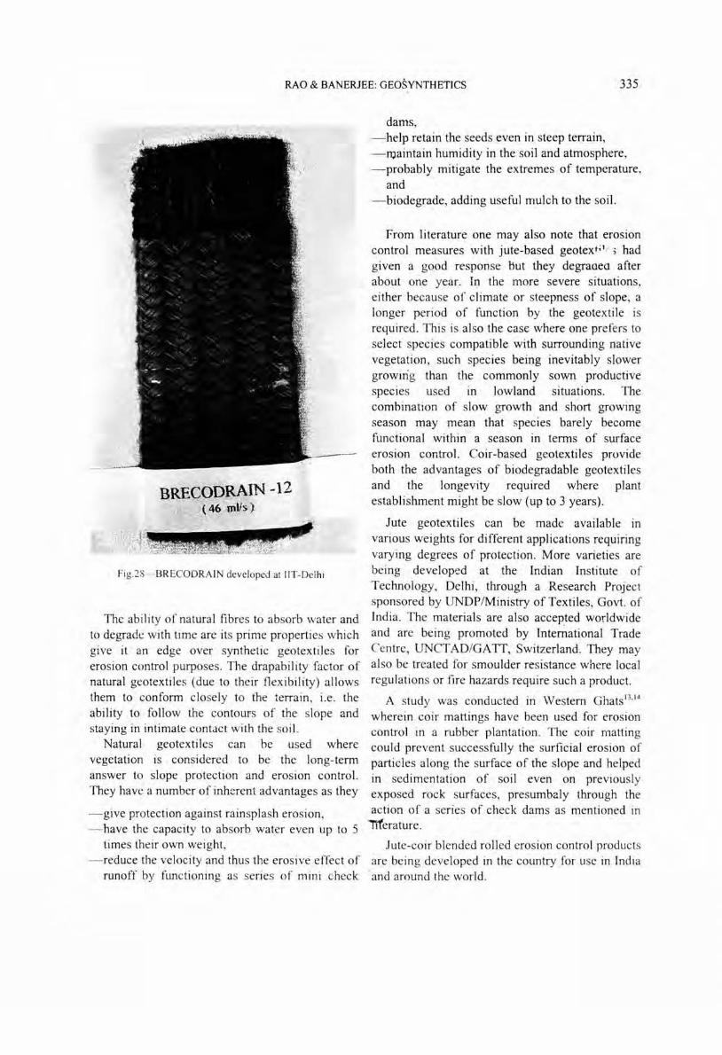
manufacturing the above drains, a new type of drain "BRECODRAIN" was developed in the Textile Technology Department at lIT-Delhi. The salient features are reported by BaneIjee '9. This drain has braided jute fibre yam as the filter and coir ropes as core drain (Fig.28).
8.3 Erosion Control with Natural Fibre Geotextiles India has about 25% of its geographical area
under mountainous terrain. Over 80% of the annual rainfall occurs from June to October. This leads to floods, causing environmental degradation which in itself is caused by excessive grazing, road construction, mining and unscientific farn1ing practices. This results in an estimated soil loss of the order 6000 million tonnes per annum. Thus, the importance of erosion control need hardly be emphasized in the Indian context.
The various causes of erosion and the different geosynthetic solutions available are detailed in a recent (1995) publication "Erosion Control with Geosynthetics" by CBIP. Experiences have been gained in the country in using polymeric geomeshes (at Ghaziabad bypass by UP PWD), gabion mattress underlain by needle-punched geotextile (on Gandhhar river in Gujarat by GERI), grouted mattress (Kakarpar canal, Gujarat) (Fig. lOb) and in many other ways·and locations.
The 1993 Market Survey on erosion control materials reveals that 55-65% of them comprise natural material. As India produces around 66 and 44 per cent of the world share of coir and jute fibres respectively, it should occupy a pre-eminent position in production, use and international marketing of natural geotextiles.
RAO & BANERJEE: GEOSYNTHETICS 335
I· ...
Fig.28- BR ECOORAIN developed at liT-Delhi
The ability of natural fibres to absorb water and to degrade with time are its prime properties which give it an edge over synthetic geotextiles for erosion control purposes. The drapability factor of natural geotextiles (due to their flexibility) allows them to conform closely to the terrain , i.e. the ability to follow the contours of the slope and staying in intimate contact with the soil.
Natural geotextiles can be used where vegetation is considered to be the long-term answer to slope protection and erosion control. They have a number of inherent advantages as they
- give protection against rainsplash erosion, - have the capacity to absorb wat.er even up to 5
times their own weight , - reduce the velocity and thus the erosive effect of
runoff by functioning as series of mini check
dams, -help retain the seeds even in steep terrain, -maintain humidity in the soil and atmosphere, -probably mitigate the extremes of temperature,
and -biodegrade, adding useful mulch to the soil.
From literature one may also notc that erosion control measures with jute-based geotex t ;l r ; had given a good response but they degradea after about one year. In the more severe situations, either because of climate or steepness of slope, a longer period of function by the geotextile is required . This is also the case where one prefers to select species compatible with surrounding native vegetation, such species being inevitably slower growing than the commonly sown productive species used In lowland situations. The combination of slow growth and short growing season may mean that species barely become functional within a season in terms of surface erosion control. Coir-based geotextiles provide both the advantages of biodegradable geotextiles and the longevity required where plant establishment might be slow (up to 3 years).
Jute geotextiles can be made available In
various weights for different applications requiring varying degrees of protection. More varieties are being developed at the Indian Institute of Technology, Delhi , through a Research Project sponsored by UNDPlMinistry of Textiles, Govt. of India. The materials are also accepted worldwide and are being promoted by International Trade Centre, UNCT AD/GAIT, Switzerland. They may also be treated for smoulder resistance where local regulations or fire hazards require such a product.
A study was conducted in Western Ghats 13•14
wherein coir mattings have been used for erosion contTol in a rubber plantation. TIlc coir matting could prevent successfully the surficial erosion of particles along the surface of the slope and helped in sedimentation of soil even on previously exposed rock surfaces, presumbaly through the action of a series of check dams as mentioned in
Ttferature.
Jute-coir blended rolled erosion control products are being developed in the country for use in India
. and around the world .
336 INDIAN 1. FIBRE TEXT. RES., DECEMBER 1997
9 Concluding Remarks 6
Before the geosynthetics can be put to effective 7
use, their characterization is of utmost importance. 8
This has been the primary emphasis of the work carried out--<leve1op/fabricate apparatus for 9
testing and evaluation. A beginning has been made to characterize the jute and coir mattings that are available in India and to develop new products for 10
wider applications: The interesting results obtained relating the hydraulic and survivability behaviour of needle-punched geotextiles with the fibre and II
process parameters can be put to use by the 12
industry. The expenence gained In use of geosynthetics in India should lend confidence among users to fully utilise the application 13
potential. Jute and coir have tremendous potential in India as well as the rest of the world for environment friendly applications. India being one 14
of the largest producers of such fibres, greater emphasis needs to be paid to research and development on these materials. 15
References
Venkatappa Rao G, Indian Ceotech J , 26 (1996) 1-94. Venkatappa Rao G, Gupta K K & Pradhan M P S, Ceotech Testing J, 15(3)(1992) 238-247.
Koerner R M & Ko F K, Proc, 2nd lilt COllf Ceotext. J
(1982) 91-96.
Christopher B R & Holtz R D, Ceotextile engineering manual, Federal Highway Administration Report 84 ( 1985).
Venkatappa Rao G, Pradhan M P S & Gupta K K, Engineering with geosynthetics,edited by G Venkatappa Rao & G V S Raju (Tata McGraw Hill , New Delhi), 1990, Chap. 5, 101-114.
Venkatappa Rao G, Gupta K K & Pradhan M P S, Ceotext Ceomem, 12 (1993) 73-87.
Ghosal A & Som N, Use of geosynthetics in India: Experiences and Potential, edited by G Venkatappa Rao & K R Saxena (CBIP, New Delhi), 1989,321-334. Dey P K, Development of a mathematical model for designing of needle punched geotextiles in hydraulic application, Ph.D. thesis , Indian Institute of Technology, New Delhi, 1995 .
Balan K, Studies on engineering behaviour and uses of geotextiles with natural [tbres, Ph.D. thesis, Indian
Environmental
Institute of Technology, New Delhi, 1995 . Venkatappa Rao G & Balan K, geotechnology with geosynthetics, Venkatappa Rao and P K Banerjee Environmental Geotechnology, New
edi ted by G
357.
(Asian Society for Delhi), 1996, 348-I Dey P K, Venkatappa Rao G & Banerjee P K, Proc, Symp
Nonwovens (The Textile Institute, North India Section), 1992,2 17-249.
2 Kaniraj S R & Venkatappa Rao G, Ceotext Ceomem, 13 (1994) 389-402.
3 Horrocks A R & D'Suza J A, Text Horizons, February (1989) 24-27.
16 Balan K & Venkatappa Rao G, Environmental geoteehnology with geosyntheties, edited by G Venkatappa Rao and P K Banerjee (Asian Society for Environmental Geotechnology, New Delhi), 1996, 358-369.
17 Venkatappa Rao G, Hariprasada Rao V & Balan K, Proe, Indian Ceoteeh Conf-94, 1994,291-295 . 4 Venkatappa Rao G, Katti !I. R &: I':armo\.;ar A K,
Engineering with geosynthetics. edited by G Venkatappa 18
Rao & G V S Raju (Tata McGraw Hill , New Delhi), 1990, 21-46.
Venkatappa Rao G & Balan K, Indian Ceoteeh J, (1997) 22-38.
19 Banerjee P K, Environmental geoteehnology with geosyntheties, edited by G Venkatappa Rao and P K Banerjee (Asian Society for Environmental Geotechnology, New Delhi), 1996,33 7-346.
5 Bajaj P~ Proc, National workshop on role of geosynthetics in water resources projects (CBIP, New Delhi). J 993, 21-28.