Embed Size (px)
Citation preview

Project: Simple Complexity
Critical Design Review (CDR) Documentation
Georgia Institute of Technology Team
A.R.E.S. Friday, January 16, 2015
2014-2015 Team A.R.E.S. NASA Student Launch Student Launch PDR
2
Table of Contents 1. Introduction ........................................................................................................................ 5 1.1. Team Summary ...................................................................................................................... 5 1.2. Launch Vehicle Summary ............................................................................................................. 5 1.2.1. Milestone Review Flysheet ...................................................................................................... 5
1.3. AGSE Summary ....................................................................................................................... 5 1.3.1. Summary of AGSE procedures and methods ...................................................................... 5
2. Changes Made Since Preliminary Design Review ...................................................... 7 2.1. Changes made to the Launch Vehicle Criteria ............................................................. 7 2.2. Changes made to the AGSE Criteria ................................................................................. 7 2.3. Changes made to the Project Plan .................................................................................... 7
3. Vehicle Criteria .................................................................................................................. 8 3.1. Design and Verification of Launch Vehicle ................................................................... 8 3.1.1. Mission Statement .......................................................................................................................... 8 3.1.2. Mission Requirements and Mission Success Criteria ...................................................... 8 3.1.3. System Design Review .................................................................................................................. 8 3.1.4. Motor Selection ................................................................................................................................. 9 3.1.5. Booster Section ................................................................................................................................ 9 3.1.6. Avionics Section ............................................................................................................................ 10 3.1.7. Avionics Electronics .................................................................................................................... 12 3.1.8. Payload Section ............................................................................................................................. 15 3.1.8.1. Payload Avionics ....................................................................................................................... 15 3.1.8.2. Analysis and Model Results ................................................................................................. 22 3.1.9. Physics Setup ................................................................................................................................. 24 3.1.10. Testing and Assembly .............................................................................................................. 32 3.1.11. Integrity of the Design ............................................................................................................. 33 3.1.11.1. Mass Statement ....................................................................................................................... 34 3.1.12. Safety and Failure Analysis (Launch Vehicle) ............................................................... 35 3.1.12.1. Vehicle Hazards ...................................................................................................................... 36 3.1.12.2. Environmental Concerns .................................................................................................... 41
3.2. Verification Overview ....................................................................................................... 41 3.2.1. Requirements Verification Matrix for Launch Vehicle and AGSE ........................... 41 3.2.2. Structural Testing ........................................................................................................................ 45 3.2.2.1. Fin Static Loading Test ........................................................................................................... 46 3.2.2.2. Fin Test Results ......................................................................................................................... 46 3.2.2.3. Finite Element Analysis (FEA) ............................................................................................ 47 3.2.3. Analysis Software ......................................................................................................................... 49 3.2.4. Flight Software .............................................................................................................................. 50
3.3. Subscale Flight and Results ............................................................................................. 51 3.4. Recovery Subsystem .......................................................................................................... 53 3.4.1. Performance Overview .............................................................................................................. 53 3.4.2. Electrical System Description ................................................................................................. 54
3.5. Mission Performance Predictions ................................................................................ 55 3.5.1. Mission Performance Prediction ........................................................................................... 55 3.5.2. Simulation Software .................................................................................................................... 55
2014-2015 Team A.R.E.S. NASA Student Launch Student Launch PDR
3
3.5.2.1. OpenRocket ................................................................................................................................. 55 3.5.2.2. MATLAB and Simulink ........................................................................................................... 55 3.5.3. Predictions ...................................................................................................................................... 56 3.5.3.1. OpenRocket Predictions ........................................................................................................ 56 3.5.3.1.1. Flight Profile Simulation .................................................................................................... 56 3.5.3.2. Stability Margins ....................................................................................................................... 56 3.5.3.3. Drift Profile Simulation .......................................................................................................... 57
3.6. AGSE Payload Integration ................................................................................................ 58 3.7. Preliminary Launch Check list ....................................................................................... 58
4. AGSE Criteria ................................................................................................................. 61 4.1. AGSE Design & Testing ...................................................................................................... 61 4.1.1. Lead Screw Static Analysis ....................................................................................................... 61 4.1.2. Control Logic Diagram ............................................................................................................... 61 4.1.3. PLIS .................................................................................................................................................... 62 4.1.4. VES ...................................................................................................................................................... 62 4.1.5. IIS ........................................................................................................................................................ 62
4.2. AGSE Approach to Workmanship .................................................................................. 63 4.2.1. AGSE Testing Plans ...................................................................................................................... 63 4.2.1.1. Component Testing ................................................................................................................. 63 4.2.1.2. Functional Testing, .................................................................................................................. 63 4.2.1.3. Static Testing .............................................................................................................................. 63 4.2.1.4. Status and Plans of Manufacturing and Assembly ..................................................... 64 4.2.1.4.1. PLIS ............................................................................................................................................. 64 4.2.1.4.2. VES .............................................................................................................................................. 64 4.2.1.4.3. IIS ................................................................................................................................................. 64
4.3. AGSE Instrumentation Precision & Measurement Repeatability ....................... 65 4.4. AGSE Electrical Subsystems ............................................................................................ 65 4.4.1. Switch and Indicator Wattage and Location .................................................................... 65 4.4.2. Drawings and Schematics ......................................................................................................... 67 4.4.3. Safety and Failure Analysis ...................................................................................................... 69
4.5. AGSE Concept Features and Definition ....................................................................... 75 4.6. Science Value ...................................................................................................................... 75
5. Project Plan ...................................................................................................................... 76 5.1. Status of Activities and Schedule ................................................................................... 76 5.1.1. Budget Plan ..................................................................................................................................... 76 5.1.2. Funding Plan .................................................................................................................................. 77 5.1.3. Timeline ........................................................................................................................................... 78 5.1.4. Educational Engagement .......................................................................................................... 78 5.1.5. First Lego League ......................................................................................................................... 79 5.1.6. Georgia Tech NSBE ...................................................................................................................... 79 5.1.7. Frederick Douglass High School ............................................................................................ 79
6. Conclusion ........................................................................................................................ 80
Appendix I: Gantt chart ....................................................................................................... 81 Appendix II: MSDS sheets ................................................................................................... 82
2014-2015 Team A.R.E.S. NASA Student Launch Student Launch PDR
4
Table of Tables Table 1 Mission Requirements and Success Criteria 8 Table 2: Material Selection 9 Table 3: Major recovery system components 12 Table 4 Launch Vehicle Specifications 17 Table 5: Nosecone Requirement Review 18 Table 6: Apogee Targeting System Requirements 20 Table 7: Mesh Statistics 24 Table 8: Statistics of computer used in meshing and simulation. 24 Table 9: Statistics of computer used in meshing and simulations 24 Table 10 Mass Statement 34 Table 11: Hazards Identification and Mitigations 36 Table 12: Hazards, Risks, and Mitigations 37 Table 13: Launch Vehicle, payload integration, and launch operations failure modes 38 Table 14: Fin Drag Parameters and Calculation 46 Table 15: Descent Properties of the Rocket for all unique configurations 53 Table 16: Parachute Area and Drag Coefficients 53 Table 17: Parachutes and Lengths occupied in launch vehicle 53 Table 18: Prelimanry Budget Breakdown 76
2014-2015 Team A.R.E.S. NASA Student Launch Student Launch PDR
5
1. Introduction 1.1. Team Summary
Team Summary School Name Georgia Institute of Technology Mailing Address North Avenue NW, Atlanta GA 30332 Team Name Team Autonomous Rocket Equipment System (A.R.E.S.) Project Title Simple Complexity Launch Vehicle Name Pyroeis Project Lead Victor R. Safety Officer Raef E. Team Advisors Dr. Eric Feron NAR Section Primary: Southern Area Launch vehiclery (SoAR) #571 NAR Contact, Number & Certification Level
Primary Contact: Joseph Mattingly NAR/TRA Number: 92646 Certification Level: Level 2 Secondary: Jorge Blanco
1.2. Launch Vehicle Summary
The Pyroeis launch vehicle has a gross-liftoff weight of approximately 17 pounds and features a Cesaroni J760 reloadable motor. The launch vehicle is constructed from 4-inch diameter G10 fiberglass tubes with G10 fiberglass couplers between sections. The total length of the rocket is 80.875 inches. The recovery system utilizes a 56 inch diameter drogue parachute that will result in a terminal velocity of 50 ft/s and a 60 inch diameter main parachute to slow the launch vehicle down to 18 ft/s with a terminal kinetic energy of 70 lbf-ft.
1.2.1. Milestone Review Flysheet
Found separately on the Georgia Tech website.
1.3. AGSE Summary
1.3.1. Summary of AGSE procedures and methods
Georgia Tech’s AGSE System, codename Bella, will be a mechanically stable platform that will house critical hardware and electrical modules in order to accomplish all mission objectives for the 2015 NASA SL Maxi-MAV/Centennial Challenge. Key components & related mission objectives for Bella are as follows:
2014-2015 Team A.R.E.S. NASA Student Launch Student Launch PDR
6
• Payload Insertion System (PLIS): An open source 5 degrees of freedom (DOF) robotic arm will be used to reliably and effectively capture the standard MaxiMAV payload.
• Vehicle Erector System (VES): The VES will incorporate launch rails upon which the LV will rest and eventually exit, and a pair of worm screws (threaded rods), each driven by a NEMA 23 stepper motor, offset from the launch rail.
• Igniter Insertion System (IIS): The IIS will use a rack-and-pinion style linear actuator powered by a 12V DC 0.07A motor with the maximum RPM of 3.5 to carry out the task of autonomously inserting a live igniter into the solid rocket motor (SRM) cavity.
The AGSE system will be controlled autonomously by an Arduino Due
microcontroller. With 512 KB of Flash memory, a DMA controller, a 32-bit core running at 84 MHz, support for 4-byte wide data operations, 54 I/O pins (12 of which can use pulse-width modulation output for servo motor control) this particular microcontroller has enough memory, computing power, and I/O pins for each aspect of the AGSE subsystem. Furthermore, it will control the seven robotic arm servo motors, the VES stepper motors, and the IIS DC motor.
2014-2015 Team A.R.E.S. NASA Student Launch Student Launch PDR
7
2. Changes Made Since Preliminary Design Review 2.1. Changes made to the Launch Vehicle Criteria • Resizing of parachutes • Motor change to Cesaroni J760
2.2. Changes made to the AGSE Criteria ROB WORKING ON IT RIGHT NOW
2.3. Changes made to the Project Plan • Logo Change • No changes to the project plan
2014-2015 Team A.R.E.S. NASA Student Launch Student Launch PDR
8
3. Vehicle Criteria 3.1. Design and Verification of Launch Vehicle
3.1.1. Mission Statement
To maintain a sustainable team dedicated to the gaining of knowledge through the designing, building, and launching of reusable launch vehicles with accompanying autonomous ground support equipment in accordance with the NASA Student Launch Guidelines.
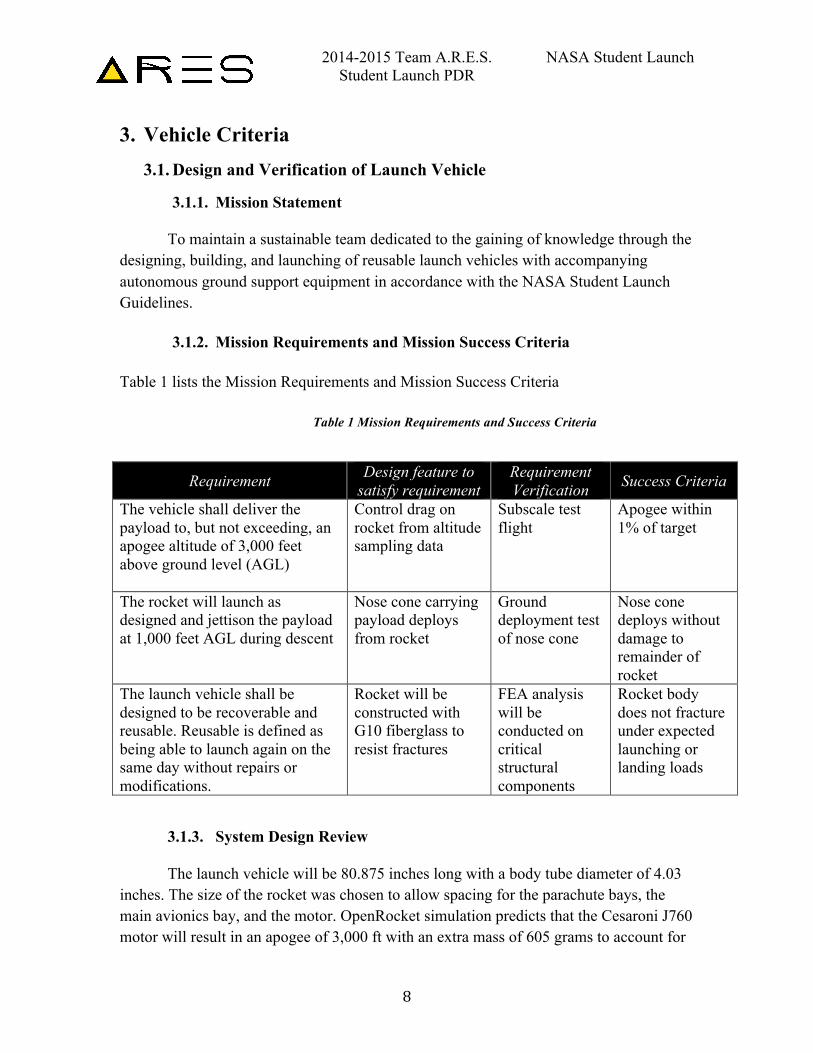
3.1.2. Mission Requirements and Mission Success Criteria Table 1 lists the Mission Requirements and Mission Success Criteria
Table 1 Mission Requirements and Success Criteria
Requirement Design feature to satisfy requirement
Requirement Verification Success Criteria
The vehicle shall deliver the payload to, but not exceeding, an apogee altitude of 3,000 feet above ground level (AGL)
Control drag on rocket from altitude sampling data
Subscale test flight
Apogee within 1% of target
The rocket will launch as designed and jettison the payload at 1,000 feet AGL during descent
Nose cone carrying payload deploys from rocket
Ground deployment test of nose cone
Nose cone deploys without damage to remainder of rocket
The launch vehicle shall be designed to be recoverable and reusable. Reusable is defined as being able to launch again on the same day without repairs or modifications.
Rocket will be constructed with G10 fiberglass to resist fractures
FEA analysis will be conducted on critical structural components
Rocket body does not fracture under expected launching or landing loads
3.1.3. System Design Review
The launch vehicle will be 80.875 inches long with a body tube diameter of 4.03 inches. The size of the rocket was chosen to allow spacing for the parachute bays, the main avionics bay, and the motor. OpenRocket simulation predicts that the Cesaroni J760 motor will result in an apogee of 3,000 ft with an extra mass of 605 grams to account for
2014-2015 Team A.R.E.S. NASA Student Launch Student Launch PDR
9
unexpected component additions. The rocket is divided into four sections: the booster section, avionics section, upper section, and payload section. Table 2 lists materials used with motivation for material selections.
Table 2: Material Selection
Component(s) Material Motivation
Body tubes G10 Fiberglass Resistance to high aerodynamic loads and ground impact
Fins G10 Fiberglass Resistance to high aerodynamic loads and ground impact
Bulkheads Plywood Cheap and lightweight
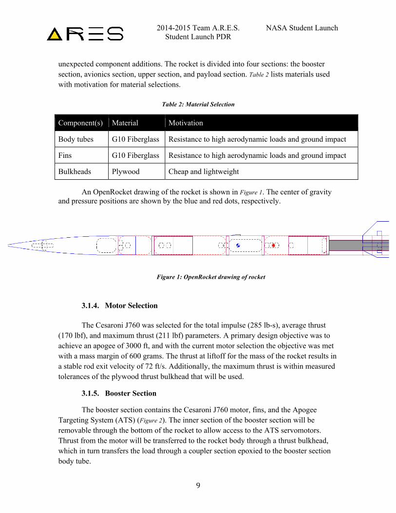
An OpenRocket drawing of the rocket is shown in Figure 1. The center of gravity and pressure positions are shown by the blue and red dots, respectively.
3.1.4. Motor Selection The Cesaroni J760 was selected for the total impulse (285 lb-s), average thrust
(170 lbf), and maximum thrust (211 lbf) parameters. A primary design objective was to achieve an apogee of 3000 ft, and with the current motor selection the objective was met with a mass margin of 600 grams. The thrust at liftoff for the mass of the rocket results in a stable rod exit velocity of 72 ft/s. Additionally, the maximum thrust is within measured tolerances of the plywood thrust bulkhead that will be used.
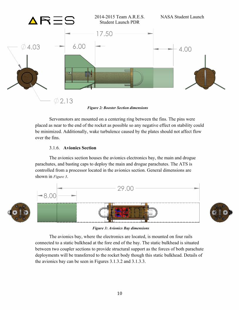
3.1.5. Booster Section
The booster section contains the Cesaroni J760 motor, fins, and the Apogee Targeting System (ATS) (Figure 2). The inner section of the booster section will be removable through the bottom of the rocket to allow access to the ATS servomotors. Thrust from the motor will be transferred to the rocket body through a thrust bulkhead, which in turn transfers the load through a coupler section epoxied to the booster section body tube.
Figure 1: OpenRocket drawing of rocket
2014-2015 Team A.R.E.S. NASA Student Launch Student Launch PDR
10
Servomotors are mounted on a centering ring between the fins. The pins were placed as near to the end of the rocket as possible so any negative effect on stability could be minimized. Additionally, wake turbulence caused by the plates should not affect flow over the fins.
3.1.6. Avionics Section
The avionics section houses the avionics electronics bay, the main and drogue parachutes, and basting caps to deploy the main and drogue parachutes. The ATS is controlled from a processor located in the avionics section. General dimensions are shown in Figure 3.
The avionics bay, where the electronics are located, is mounted on four rails connected to a static bulkhead at the fore end of the bay. The static bulkhead is situated between two coupler sections to provide structural support as the forces of both parachute deployments will be transferred to the rocket body though this static bulkhead. Details of the avionics bay can be seen in Figures 3.1.3.2 and 3.1.3.3.
Figure 2: Booster Section dimensions
Figure 3: Avionics Bay dimensions
2014-2015 Team A.R.E.S. NASA Student Launch Student Launch PDR
11
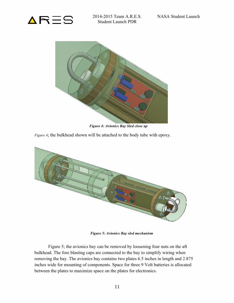
Figure 4; the bulkhead shown will be attached to the body tube with epoxy.
Figure 5; the avionics bay can be removed by loosening four nuts on the aft bulkhead. The fore blasting caps are connected to the bay to simplify wiring when removing the bay. The avionics bay contains two plates 6.5 inches in length and 2.875 inches wide for mounting of components. Space for three 9 Volt batteries is allocated between the plates to maximize space on the plates for electronics.
Figure 4: Avionics Bay Sled close up
Figure 5: Avionics Bay sled mechanism
2014-2015 Team A.R.E.S. NASA Student Launch Student Launch PDR
12
3.1.7. Avionics Electronics
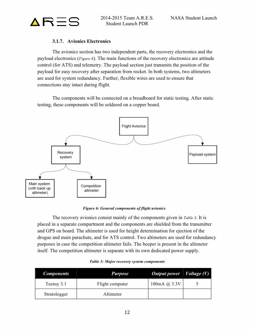
The avionics section has two independent parts, the recovery electronics and the payload electronics (Figure 6). The main functions of the recovery electronics are attitude control (for ATS) and telemetry. The payload section just transmits the position of the payload for easy recovery after separation from rocket. In both systems, two altimeters are used for system redundancy. Further, flexible wires are used to ensure that connections stay intact during flight.
The components will be connected on a breadboard for static testing. After static testing, these components will be soldered on a copper board.
Figure 1. General components of flight avionics.
The recovery avionics consist mainly of the components given in Table 3. It is placed in a separate compartment and the components are shielded from the transmitter and GPS on board. The altimeter is used for height determination for ejection of the drogue and main parachute, and for ATS control. Two altimeters are used for redundancy purposes in case the competition altimeter fails. The beeper is present in the altimeter itself. The competition altimeter is separate with its own dedicated power supply.
Table 3: Major recovery system components
Components Purpose Output power Voltage (V)
Teensy 3.1 Flight computer 100mA @ 3.3V 5
Stratologger Altimeter
Figure 6: General components of flight avionics
2014-2015 Team A.R.E.S. NASA Student Launch Student Launch PDR
13
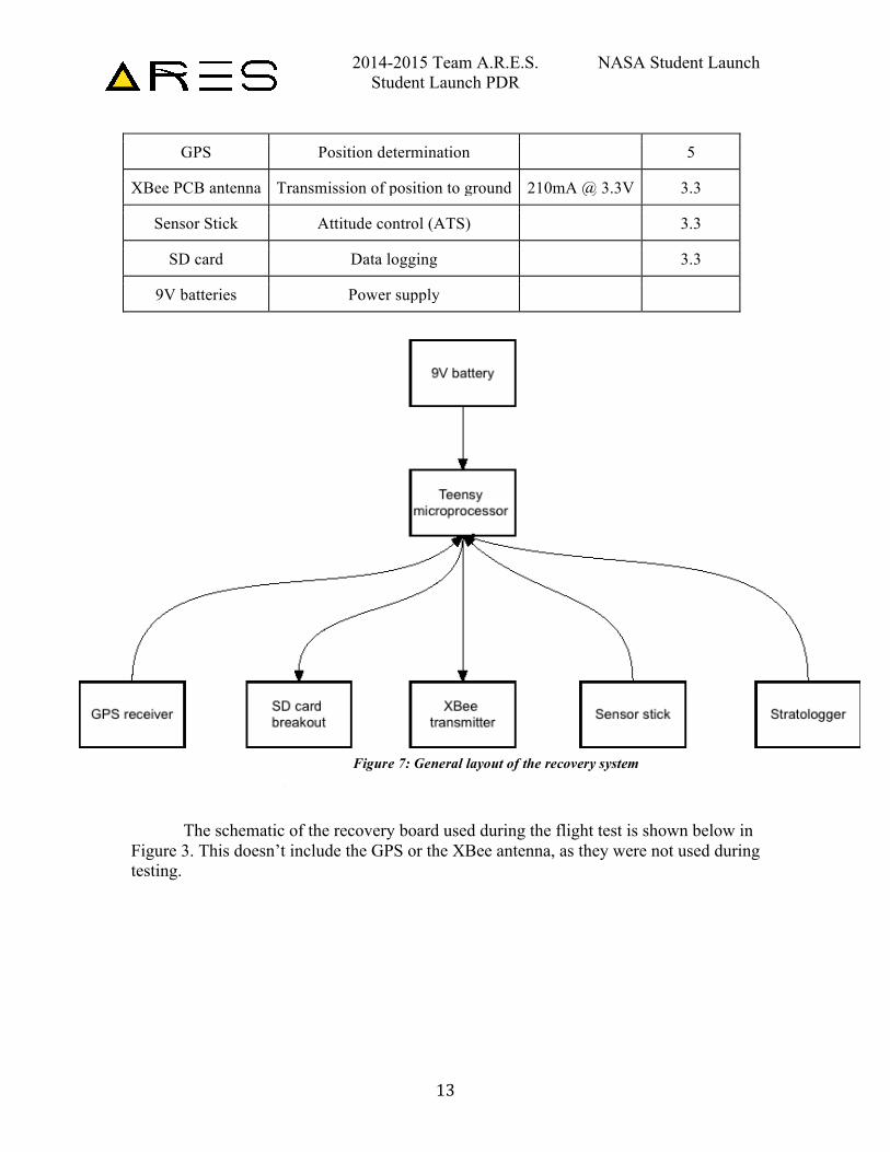
GPS Position determination
5
XBee PCB antenna Transmission of position to ground 210mA @ 3.3V 3.3
Sensor Stick Attitude control (ATS)
3.3
SD card Data logging
3.3
9V batteries Power supply
Figure 2. General layout of the recovery system.
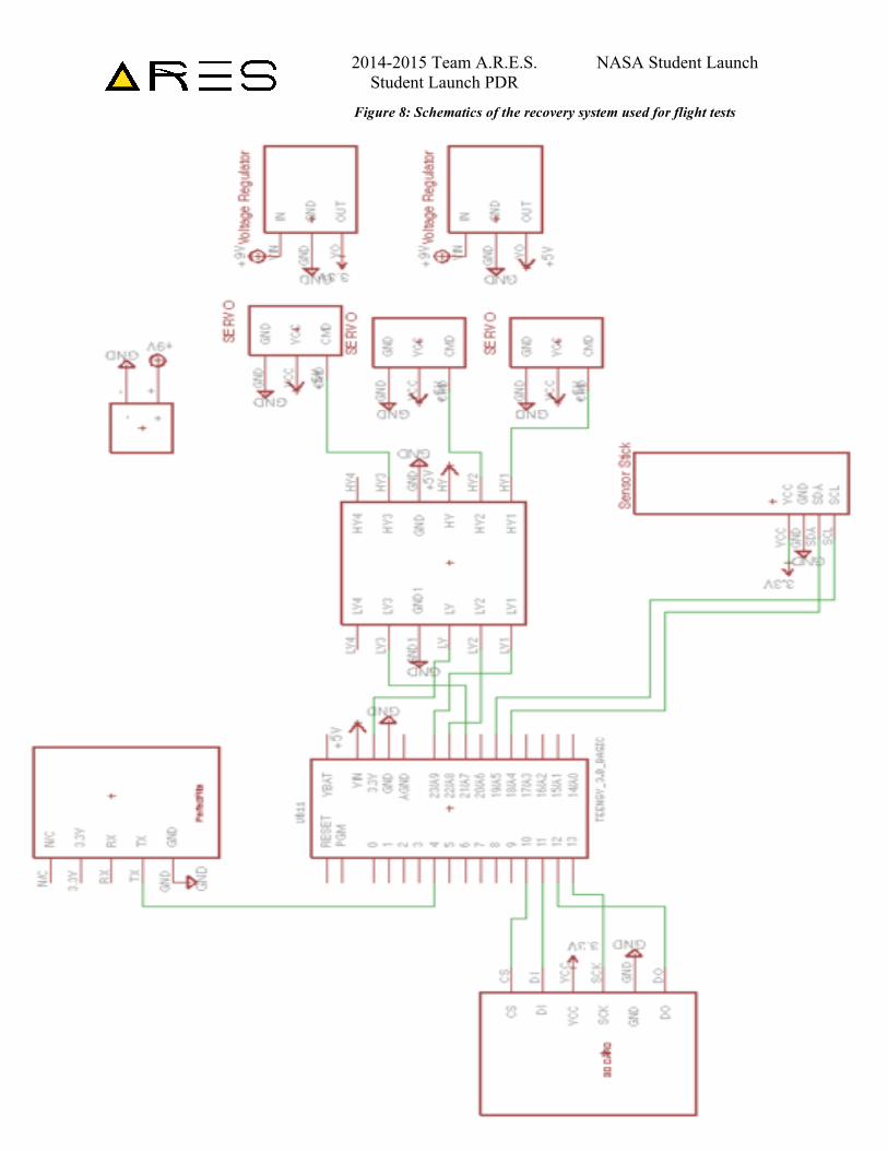
The schematic of the recovery board used during the flight test is shown below in Figure 3. This doesn’t include the GPS or the XBee antenna, as they were not used during testing.
Figure 7: General layout of the recovery system
2014-2015 Team A.R.E.S. NASA Student Launch Student Launch PDR
14
Figure 8: Schematics of the recovery system used for flight tests
2014-2015 Team A.R.E.S. NASA Student Launch Student Launch PDR
15
3.1.8. Payload Section
3.1.8.1. Payload Avionics
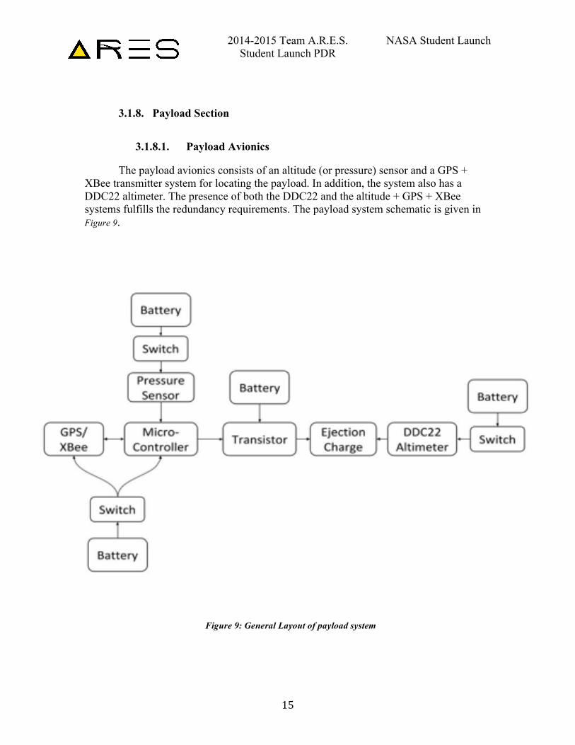
The payload avionics consists of an altitude (or pressure) sensor and a GPS + XBee transmitter system for locating the payload. In addition, the system also has a DDC22 altimeter. The presence of both the DDC22 and the altitude + GPS + XBee systems fulfills the redundancy requirements. The payload system schematic is given in Figure 9.
Figure 9: General Layout of payload system
2014-2015 Team A.R.E.S. NASA Student Launch Student Launch PDR
16
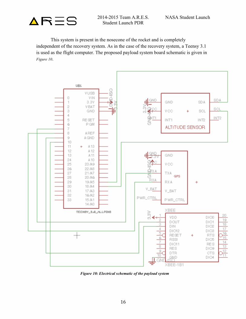
This system is present in the nosecone of the rocket and is completely independent of the recovery system. As in the case of the recovery system, a Teensy 3.1 is used as the flight computer. The proposed payload system board schematic is given in Figure 10.
Figure 10: Electrical schematic of the payload system
2014-2015 Team A.R.E.S. NASA Student Launch Student Launch PDR
17
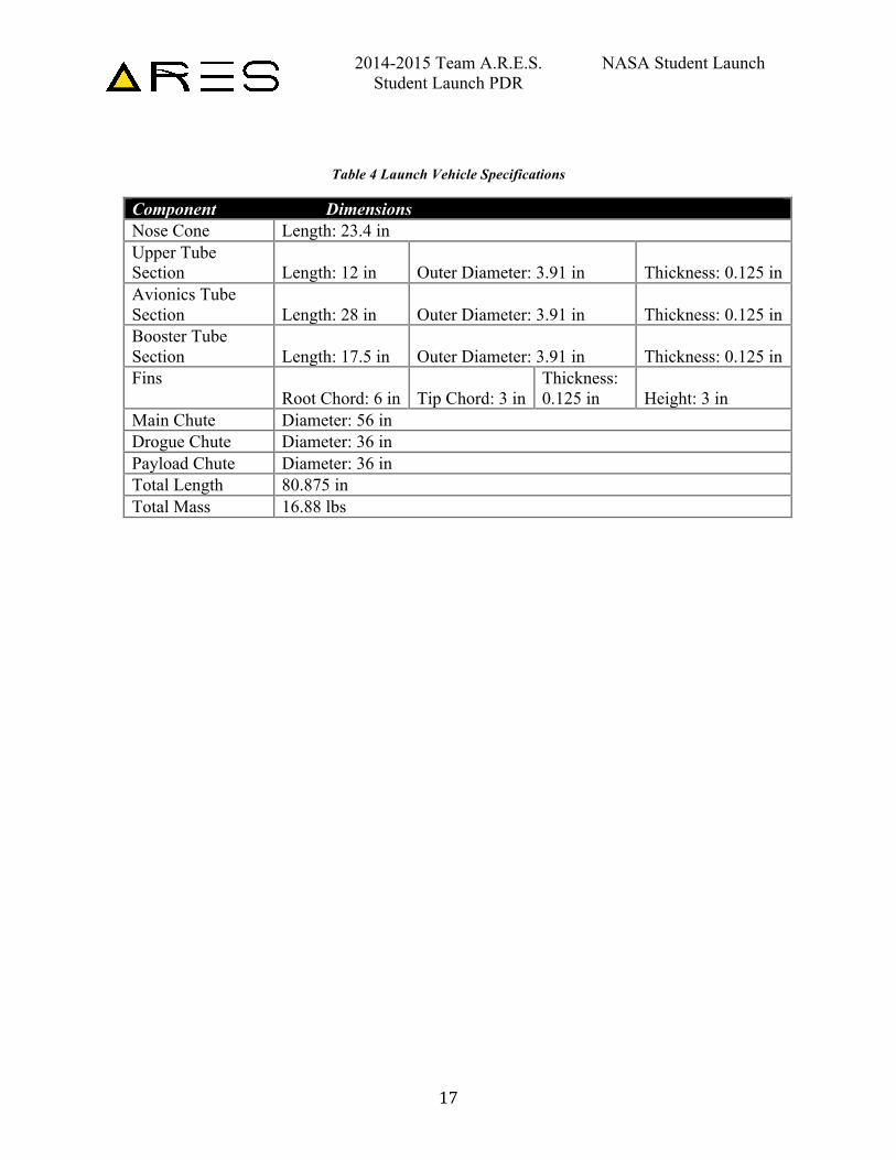
Table 4 Launch Vehicle Specifications
Component Dimensions Nose Cone Length: 23.4 in Upper Tube Section Length: 12 in Outer Diameter: 3.91 in Thickness: 0.125 in Avionics Tube Section Length: 28 in Outer Diameter: 3.91 in Thickness: 0.125 in Booster Tube Section Length: 17.5 in Outer Diameter: 3.91 in Thickness: 0.125 in Fins
Root Chord: 6 in Tip Chord: 3 in Thickness: 0.125 in Height: 3 in
Main Chute Diameter: 56 in Drogue Chute Diameter: 36 in Payload Chute Diameter: 36 in Total Length 80.875 in Total Mass 16.88 lbs
2014-2015 Team A.R.E.S. NASA Student Launch Student Launch PDR
18
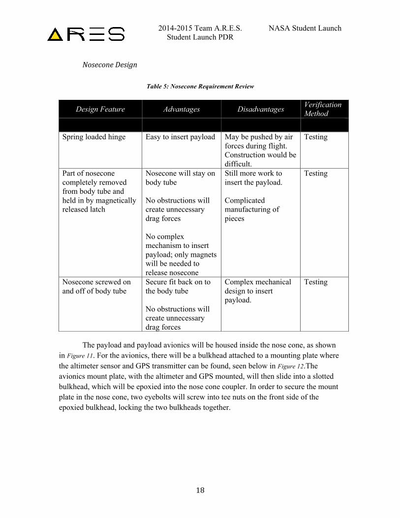
Nosecone Design
Table 5: Nosecone Requirement Review
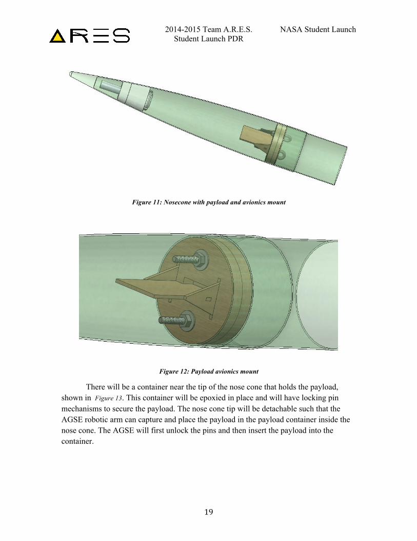
The payload and payload avionics will be housed inside the nose cone, as shown
in Figure 11. For the avionics, there will be a bulkhead attached to a mounting plate where the altimeter sensor and GPS transmitter can be found, seen below in Figure 12.The avionics mount plate, with the altimeter and GPS mounted, will then slide into a slotted bulkhead, which will be epoxied into the nose cone coupler. In order to secure the mount plate in the nose cone, two eyebolts will screw into tee nuts on the front side of the epoxied bulkhead, locking the two bulkheads together.
Design Feature Advantages Disadvantages Verification Method
Spring loaded hinge Easy to insert payload May be pushed by air forces during flight. Construction would be difficult.
Testing
Part of nosecone completely removed from body tube and held in by magnetically released latch
Nosecone will stay on body tube No obstructions will create unnecessary drag forces No complex mechanism to insert payload; only magnets will be needed to release nosecone
Still more work to insert the payload. Complicated manufacturing of pieces
Testing
Nosecone screwed on and off of body tube
Secure fit back on to the body tube No obstructions will create unnecessary drag forces
Complex mechanical design to insert payload.
Testing
2014-2015 Team A.R.E.S. NASA Student Launch Student Launch PDR
19
Figure 11: Nosecone with payload and avionics mount
Figure 12: Payload avionics mount
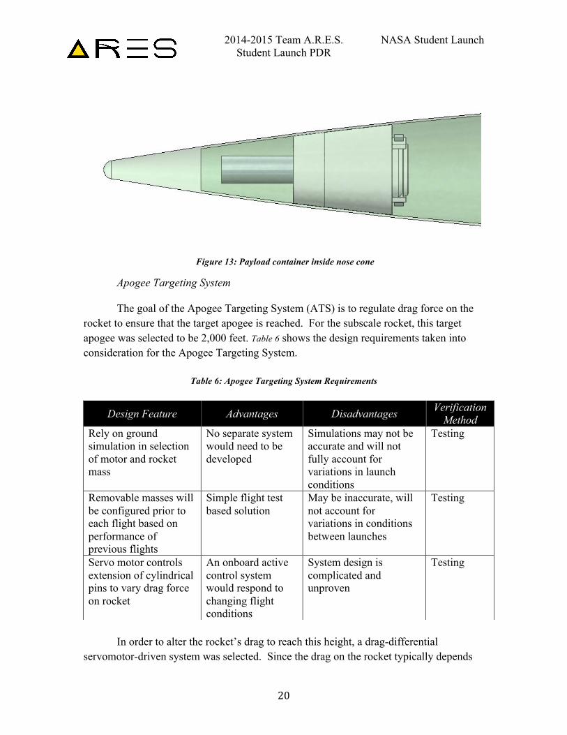
There will be a container near the tip of the nose cone that holds the payload, shown in Figure 13. This container will be epoxied in place and will have locking pin mechanisms to secure the payload. The nose cone tip will be detachable such that the AGSE robotic arm can capture and place the payload in the payload container inside the nose cone. The AGSE will first unlock the pins and then insert the payload into the container.
2014-2015 Team A.R.E.S. NASA Student Launch Student Launch PDR
20
Figure 13: Payload container inside nose cone
Apogee Targeting System The goal of the Apogee Targeting System (ATS) is to regulate drag force on the
rocket to ensure that the target apogee is reached. For the subscale rocket, this target apogee was selected to be 2,000 feet. Table 6 shows the design requirements taken into consideration for the Apogee Targeting System.
Table 6: Apogee Targeting System Requirements
In order to alter the rocket’s drag to reach this height, a drag-differential
servomotor-driven system was selected. Since the drag on the rocket typically depends
Design Feature Advantages Disadvantages Verification Method
Rely on ground simulation in selection of motor and rocket mass
No separate system would need to be developed
Simulations may not be accurate and will not fully account for variations in launch conditions
Testing
Removable masses will be configured prior to each flight based on performance of previous flights
Simple flight test based solution
May be inaccurate, will not account for variations in conditions between launches
Testing
Servo motor controls extension of cylindrical pins to vary drag force on rocket
An onboard active control system would respond to changing flight conditions
System design is complicated and unproven
Testing
2014-2015 Team A.R.E.S. NASA Student Launch Student Launch PDR
21
on the square of velocity in traditional fluid mechanics formulation, this constituted a nonlinear, time variant control problem, and accordingly required careful, largely empirically driven design in MATLAB. In order to determine the expected performance of the rocket (and hence define “deviance” from expected performance), the team decided to construct a Simulink model containing realistic models of the following four entities:
• Rocket (mass, drag coefficient, etc.) • The standard Earth atmosphere • The motor selected for the rocket (with given mass and thrust properties) • The ATS and its controller logic.
This “nominal model” was used as an ideal trajectory for the rocket to achieve. Since real-world performance would likely involve deviations from “nominal”, the following potential sources of variance were considered in the dynamic model:
• Variance in motor mass/thrust profile • Variance due to wind
Since a local (Alabama-based) wind model had not been constructed, the team modeled the effects of wind variance as height error (i.e. deviation from “nominal height”, as described below). The purpose of the ATS would be to measure the height starting at launch through altimeter data, measure its deviation from “nominal height” at that time, and actuate the ATS accordingly to either add or subtract drag from the rocket to mitigate the deviation.
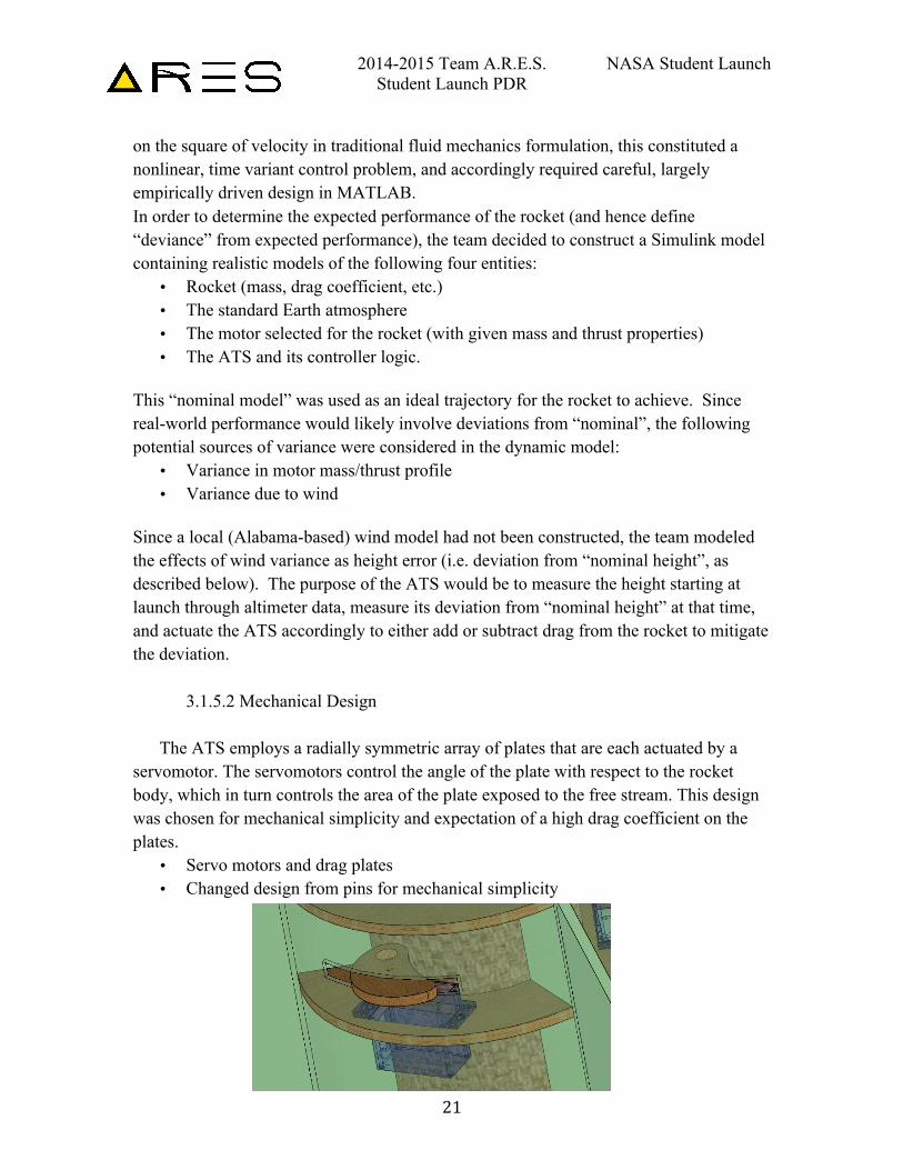
3.1.5.2 Mechanical Design
The ATS employs a radially symmetric array of plates that are each actuated by a servomotor. The servomotors control the angle of the plate with respect to the rocket body, which in turn controls the area of the plate exposed to the free stream. This design was chosen for mechanical simplicity and expectation of a high drag coefficient on the plates.
• Servo motors and drag plates • Changed design from pins for mechanical simplicity
2014-2015 Team A.R.E.S. NASA Student Launch Student Launch PDR
22
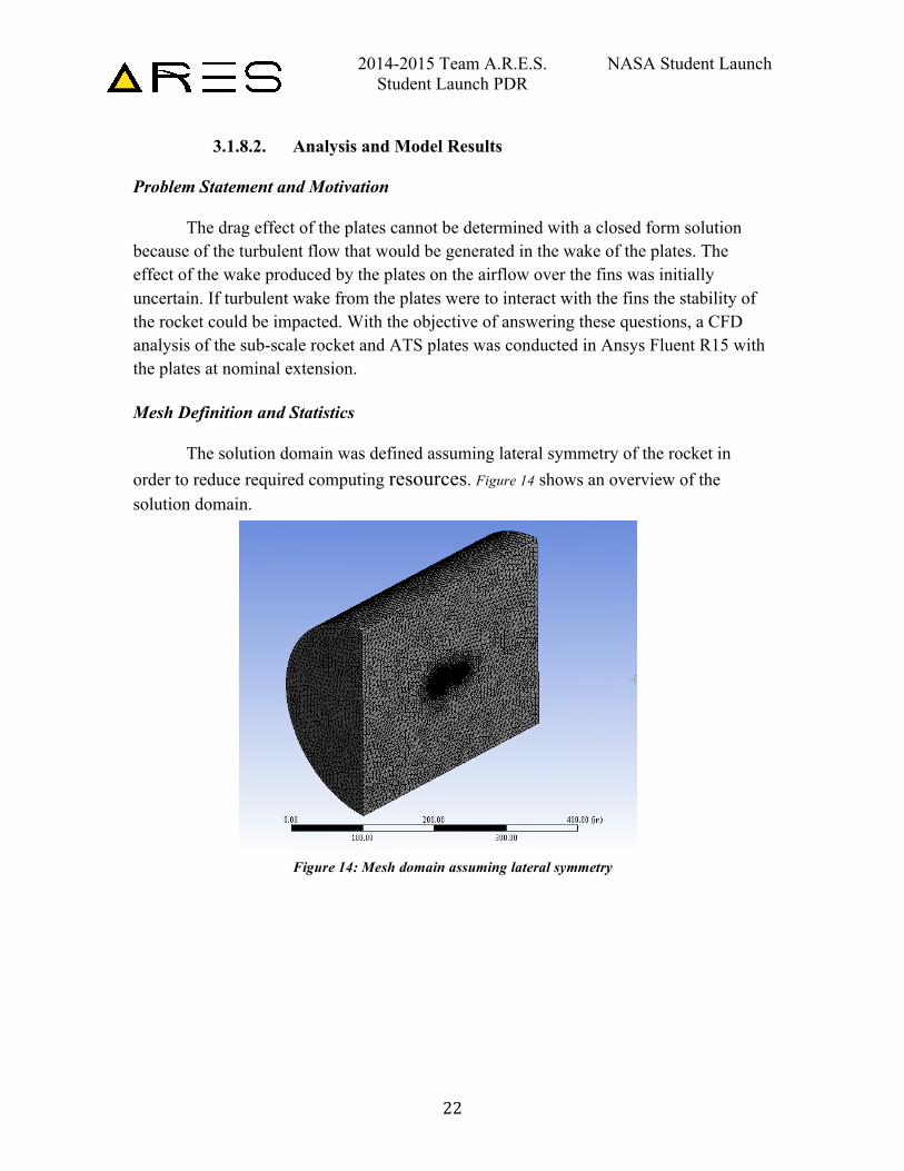
3.1.8.2. Analysis and Model Results Problem Statement and Motivation The drag effect of the plates cannot be determined with a closed form solution because of the turbulent flow that would be generated in the wake of the plates. The effect of the wake produced by the plates on the airflow over the fins was initially uncertain. If turbulent wake from the plates were to interact with the fins the stability of the rocket could be impacted. With the objective of answering these questions, a CFD analysis of the sub-scale rocket and ATS plates was conducted in Ansys Fluent R15 with the plates at nominal extension. Mesh Definition and Statistics
The solution domain was defined assuming lateral symmetry of the rocket in order to reduce required computing resources. Figure 14 shows an overview of the solution domain.
Figure 14: Mesh domain assuming lateral symmetry
2014-2015 Team A.R.E.S. NASA Student Launch Student Launch PDR
23
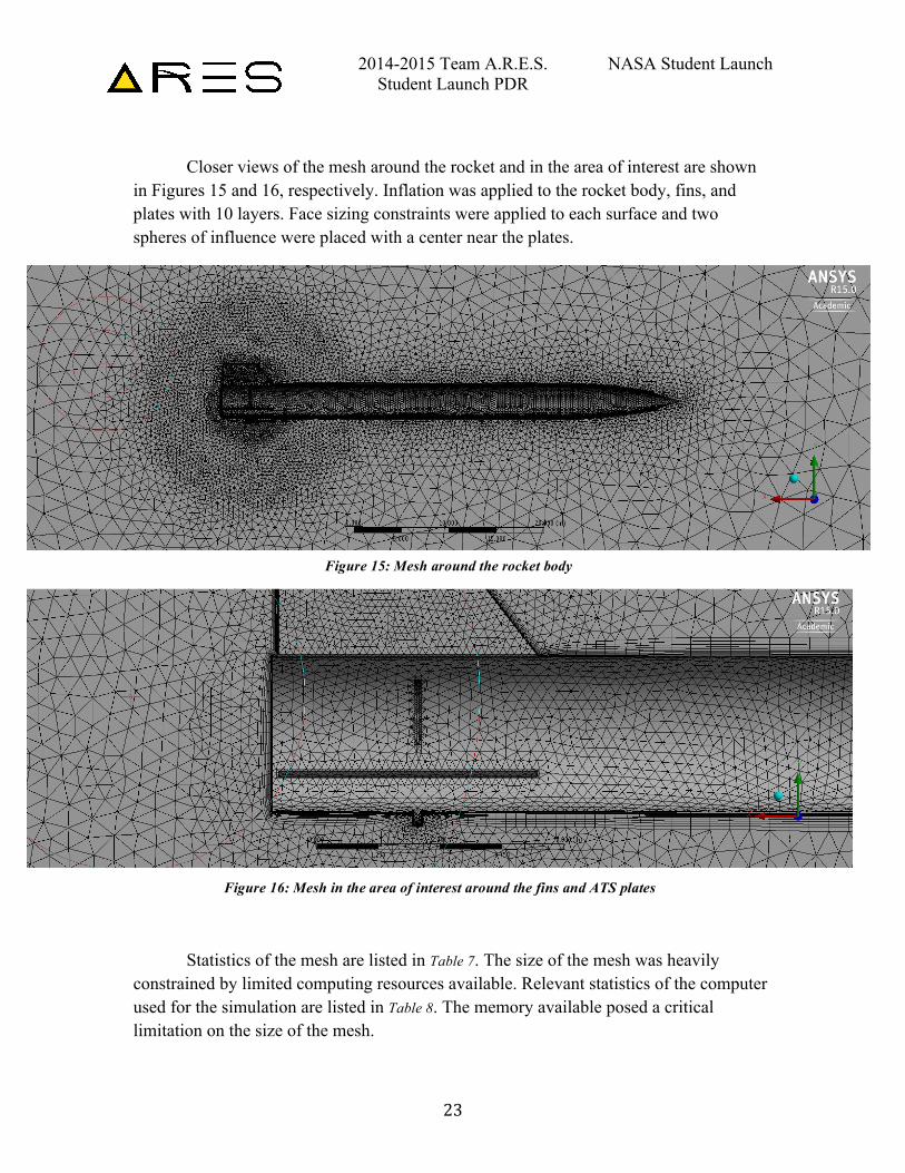
Closer views of the mesh around the rocket and in the area of interest are shown
in Figures 15 and 16, respectively. Inflation was applied to the rocket body, fins, and plates with 10 layers. Face sizing constraints were applied to each surface and two spheres of influence were placed with a center near the plates.
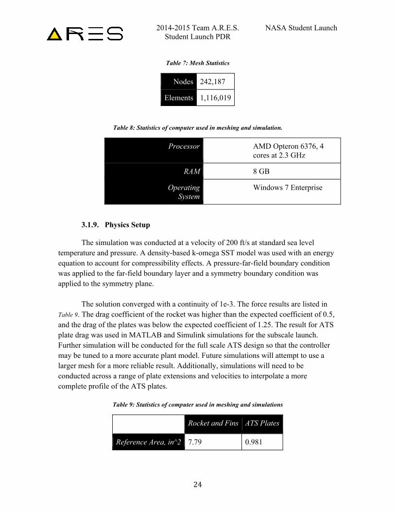
Statistics of the mesh are listed in Table 7. The size of the mesh was heavily
constrained by limited computing resources available. Relevant statistics of the computer used for the simulation are listed in Table 8. The memory available posed a critical limitation on the size of the mesh.
Figure 15: Mesh around the rocket body
Figure 16: Mesh in the area of interest around the fins and ATS plates
2014-2015 Team A.R.E.S. NASA Student Launch Student Launch PDR
24
Table 7: Mesh Statistics
Nodes 242,187
Elements 1,116,019
Table 8: Statistics of computer used in meshing and simulation.
Processor AMD Opteron 6376, 4 cores at 2.3 GHz
RAM 8 GB
Operating System
Windows 7 Enterprise
3.1.9. Physics Setup
The simulation was conducted at a velocity of 200 ft/s at standard sea level temperature and pressure. A density-based k-omega SST model was used with an energy equation to account for compressibility effects. A pressure-far-field boundary condition was applied to the far-field boundary layer and a symmetry boundary condition was applied to the symmetry plane.
The solution converged with a continuity of 1e-3. The force results are listed in Table 9. The drag coefficient of the rocket was higher than the expected coefficient of 0.5, and the drag of the plates was below the expected coefficient of 1.25. The result for ATS plate drag was used in MATLAB and Simulink simulations for the subscale launch. Further simulation will be conducted for the full scale ATS design so that the controller may be tuned to a more accurate plant model. Future simulations will attempt to use a larger mesh for a more reliable result. Additionally, simulations will need to be conducted across a range of plate extensions and velocities to interpolate a more complete profile of the ATS plates.
Table 9: Statistics of computer used in meshing and simulations
Rocket and Fins ATS Plates
Reference Area, in^2 7.79 0.981
2014-2015 Team A.R.E.S. NASA Student Launch Student Launch PDR
25
Drag Force, lbs 1.78 0.34
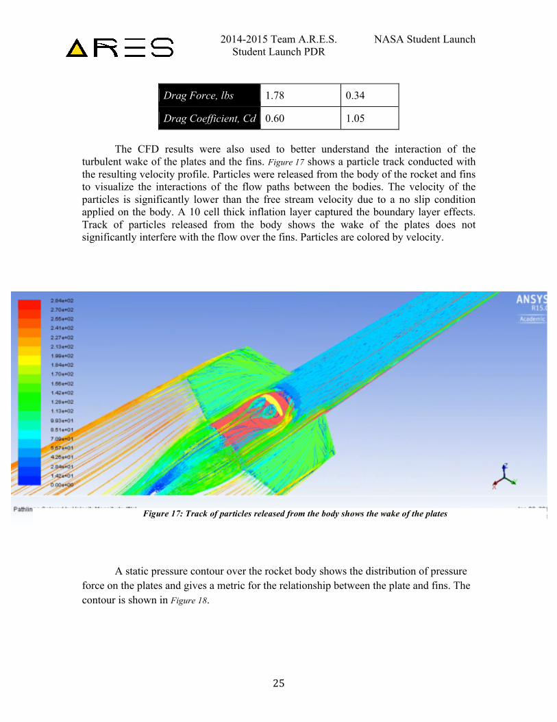
Drag Coefficient, Cd 0.60 1.05 The CFD results were also used to better understand the interaction of the turbulent wake of the plates and the fins. Figure 17 shows a particle track conducted with the resulting velocity profile. Particles were released from the body of the rocket and fins to visualize the interactions of the flow paths between the bodies. The velocity of the particles is significantly lower than the free stream velocity due to a no slip condition applied on the body. A 10 cell thick inflation layer captured the boundary layer effects. Track of particles released from the body shows the wake of the plates does not significantly interfere with the flow over the fins. Particles are colored by velocity.
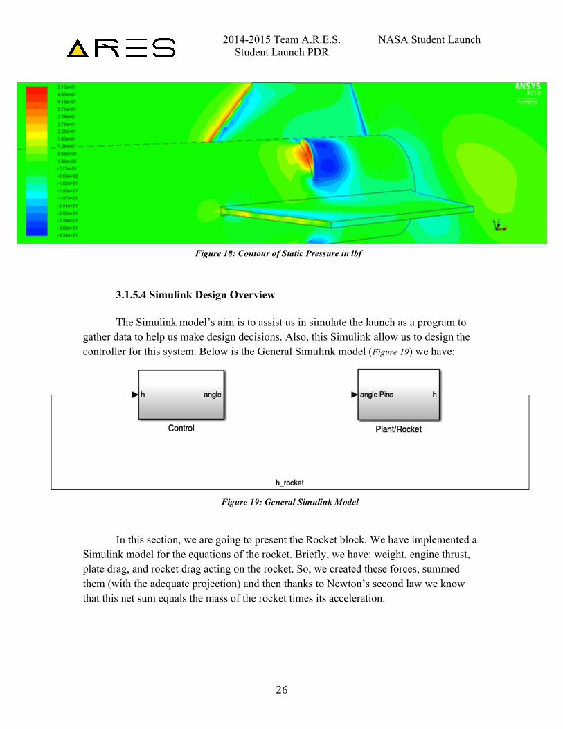
A static pressure contour over the rocket body shows the distribution of pressure force on the plates and gives a metric for the relationship between the plate and fins. The contour is shown in Figure 18.
Figure 17: Track of particles released from the body shows the wake of the plates
2014-2015 Team A.R.E.S. NASA Student Launch Student Launch PDR
26
3.1.5.4 Simulink Design Overview
The Simulink model’s aim is to assist us in simulate the launch as a program to
gather data to help us make design decisions. Also, this Simulink allow us to design the controller for this system. Below is the General Simulink model (Figure 19) we have:
In this section, we are going to present the Rocket block. We have implemented a
Simulink model for the equations of the rocket. Briefly, we have: weight, engine thrust, plate drag, and rocket drag acting on the rocket. So, we created these forces, summed them (with the adequate projection) and then thanks to Newton’s second law we know that this net sum equals the mass of the rocket times its acceleration.
Figure 18: Contour of Static Pressure in lbf
Figure 19: General Simulink Model
2014-2015 Team A.R.E.S. NASA Student Launch Student Launch PDR
27
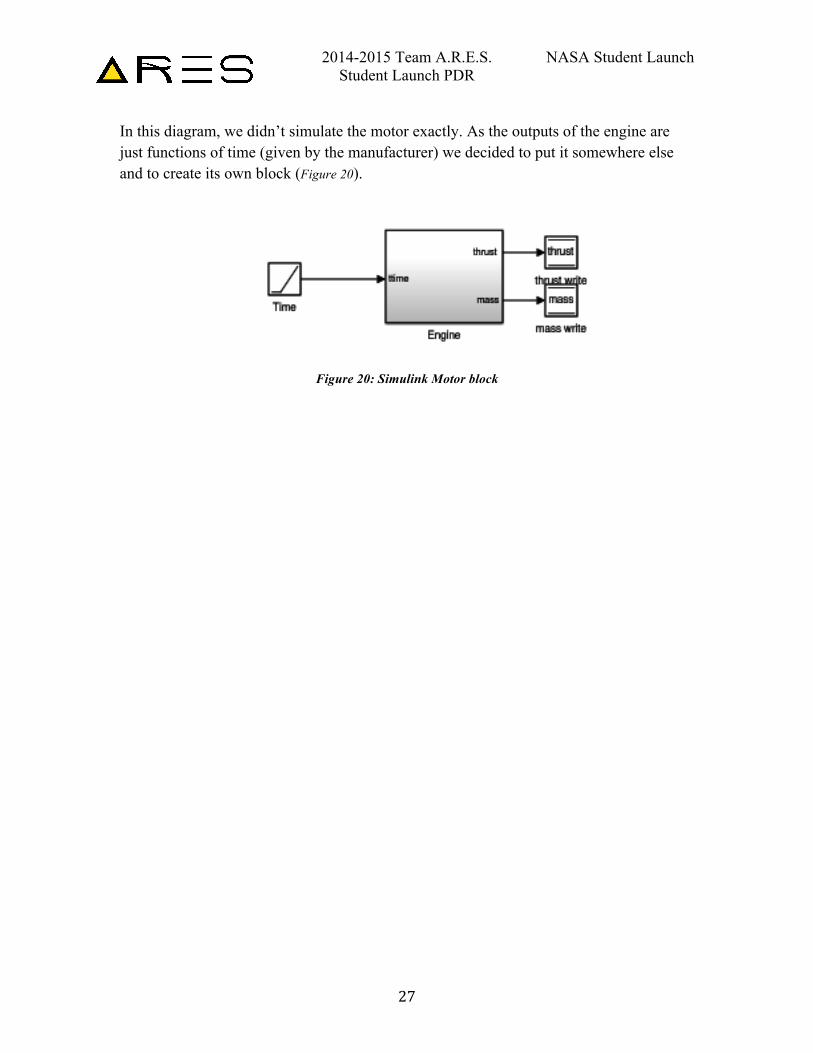
In this diagram, we didn’t simulate the motor exactly. As the outputs of the engine are just functions of time (given by the manufacturer) we decided to put it somewhere else and to create its own block (Figure 20).
Figure 20: Simulink Motor block
2014-2015 Team A.R.E.S. NASA Student Launch Student Launch PDR
28
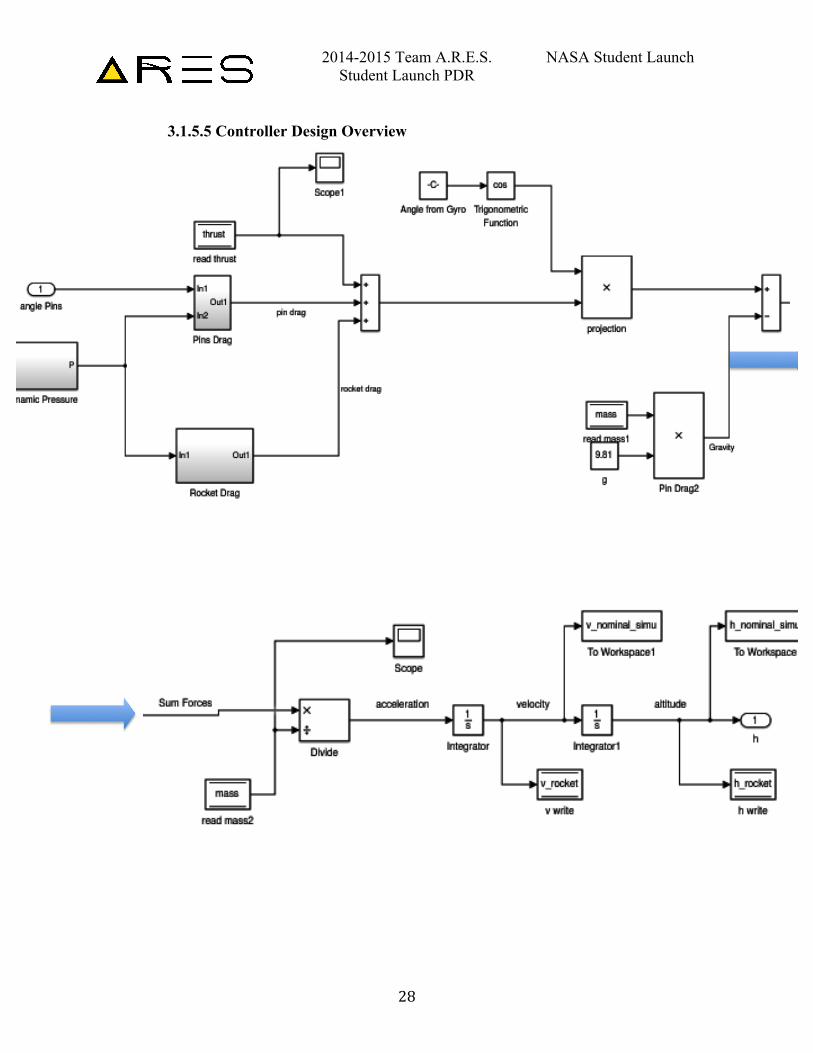
3.1.5.5 Controller Design Overview
2014-2015 Team A.R.E.S. NASA Student Launch Student Launch PDR
29
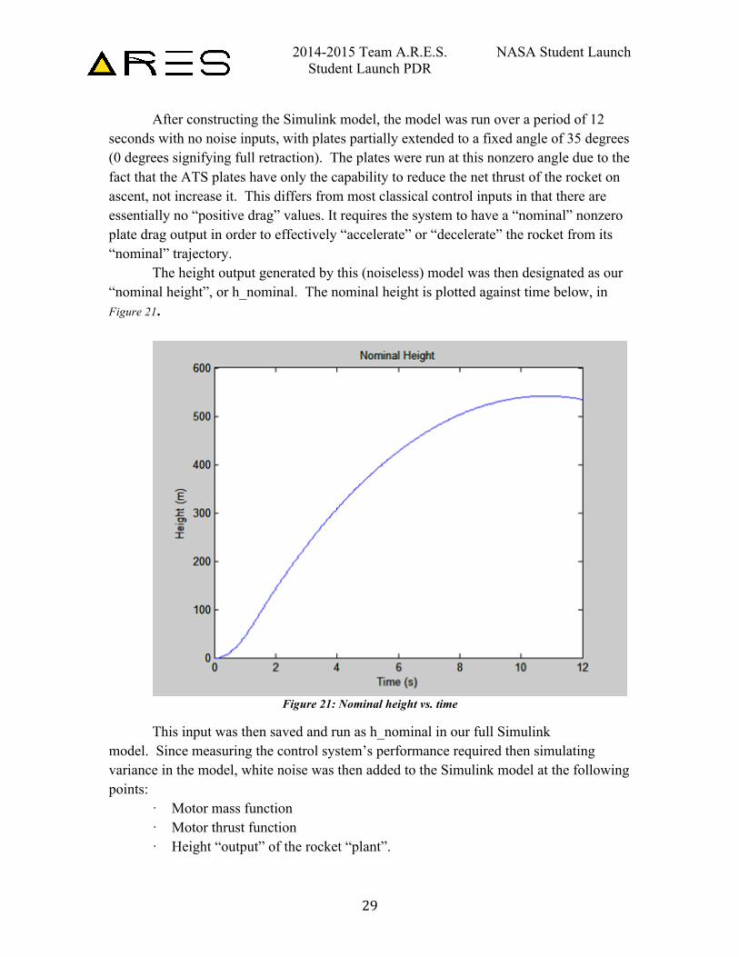
After constructing the Simulink model, the model was run over a period of 12 seconds with no noise inputs, with plates partially extended to a fixed angle of 35 degrees (0 degrees signifying full retraction). The plates were run at this nonzero angle due to the fact that the ATS plates have only the capability to reduce the net thrust of the rocket on ascent, not increase it. This differs from most classical control inputs in that there are essentially no “positive drag” values. It requires the system to have a “nominal” nonzero plate drag output in order to effectively “accelerate” or “decelerate” the rocket from its “nominal” trajectory.
The height output generated by this (noiseless) model was then designated as our “nominal height”, or h_nominal. The nominal height is plotted against time below, in Figure 21.
Figure 21: Nominal height vs. time
This input was then saved and run as h_nominal in our full Simulink model. Since measuring the control system’s performance required then simulating variance in the model, white noise was then added to the Simulink model at the following points:
· Motor mass function · Motor thrust function · Height “output” of the rocket “plant”.
2014-2015 Team A.R.E.S. NASA Student Launch Student Launch PDR
30
The difference between h_nominal and the actual (variance-influenced) model height was then used as the “error” driving the drag-plate controller. The next step was to design said controller, using the integral-squared error generated by the model over a twelve-second interval to evaluate controller performance.
3.1.5.6 PID Controller Design First, a proportional-integral-derivative (PID) controller design was considered. This PID controller, in accordance with its name, regulates the response of the drag plates through the sum of three gains based on the error. The proportional gain simply multiplies the error by a constant, whereas the derivative and integral gains multiply the time derivative and time integral of the error, respectively, by constants. To determine the appropriate gains, the model was run repeatedly with the noise in motor mass, motor thrust, and height output turned on, and iterating on the three gains. (The automatic PID controller tuning in Simulink was unavailable, due to the extreme nonlinearity of the model.)
All noise sources were assumed to be normally distributed. The parameters of the noise were as follows:
• The height output noise was set at a mean of 0, a standard deviation of 15 feet, and a sample time of 0.1 seconds. It was added to the output height.
• The mass and motor noise were multiplied by a constant with a mean of 1, a standard deviation of 0.2, and a sample time of 0.3 seconds.
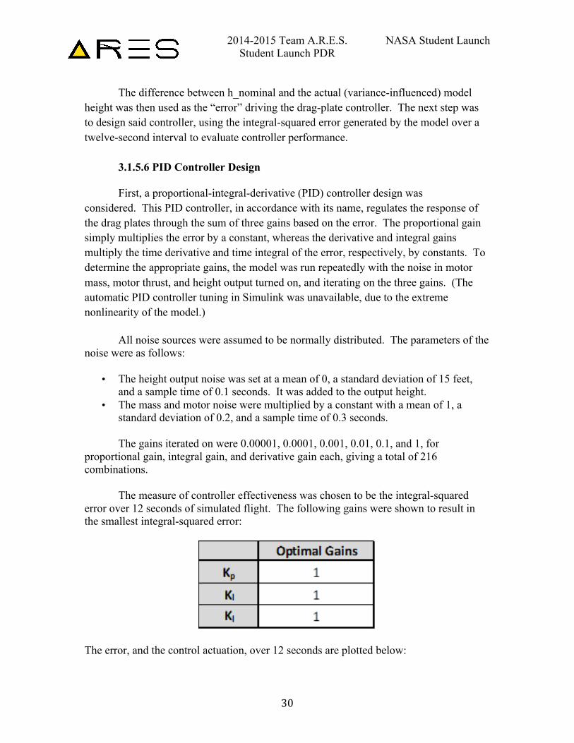
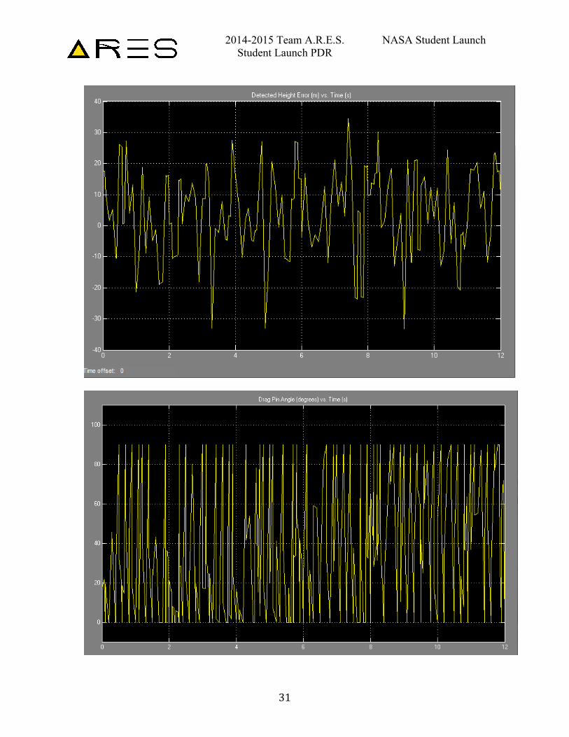
The gains iterated on were 0.00001, 0.0001, 0.001, 0.01, 0.1, and 1, for proportional gain, integral gain, and derivative gain each, giving a total of 216 combinations. The measure of controller effectiveness was chosen to be the integral-squared error over 12 seconds of simulated flight. The following gains were shown to result in the smallest integral-squared error:
The error, and the control actuation, over 12 seconds are plotted below:
2014-2015 Team A.R.E.S. NASA Student Launch Student Launch PDR
31
2014-2015 Team A.R.E.S. NASA Student Launch Student Launch PDR
32
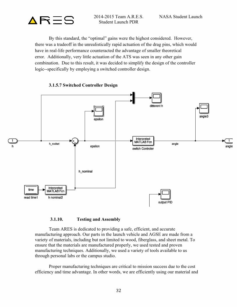
By this standard, the “optimal” gains were the highest considered. However, there was a tradeoff in the unrealistically rapid actuation of the drag pins, which would have in real-life performance counteracted the advantage of smaller theoretical error. Additionally, very little actuation of the ATS was seen in any other gain combination. Due to this result, it was decided to simplify the design of the controller logic--specifically by employing a switched controller design.
3.1.5.7 Switched Controller Design
3.1.10. Testing and Assembly
Team ARES is dedicated to providing a safe, efficient, and accurate manufacturing approach. Our parts in the launch vehicle and AGSE are made from a variety of materials, including but not limited to wood, fiberglass, and sheet metal. To ensure that the materials are manufactured properly, we used tested and proven manufacturing techniques. Additionally, we used a variety of tools available to us through personal labs or the campus studio.
Proper manufacturing techniques are critical to mission success due to the cost efficiency and time advantage. In other words, we are efficiently using our material and
2014-2015 Team A.R.E.S. NASA Student Launch Student Launch PDR
33
not wasting any time or resources manufacturing them. These techniques are useful in time critical construction parts. Furthermore, every tool we used to manufacture parts was chosen with the aforementioned ideals (safety, efficiency, and accuracy). For example, the laser cutter was used to manufacture the bulkheads (made out of plywood) because of the accuracy and consistency the laser cutter provides.
In our manufacturing approach, not only were we manufacturing parts, we had to construct “jigs” that assisted in the process and were used for important procedures and testing. The Manufacturing Assisting Contraptions (MAC) was used for assembling the fins on the subscale in an accurate manner. Furthermore, the MAC’s assisted in the Coupler position, but more specifically, the avionics bay uses .75” coupler sections to hold the bay in place, therefore the position must be accurate and precise.
Team ARES has already successfully performed various testing, including two (2) subscale launches and structural testing. However, Team ARES has more planned testing with a focus on the ATS. The ATS will be heavily tested with a wind tunnel testing to create a drag profile by integrating coefficients into existing in-house-developed simulation package. Additionally, a third (3) and final subscale test will be used to tune the launch model for accurate apogee targeting. In addition to physical testing, more Solidworks FEA testing on various components will be carried out to ensure structural integrity.
The commercially purchased fiberglass tubes have arrived, and the accompanying bulkheads have been manufactured with the manufacturing process listed above in mind. Further parts will be manufactured after significant design reviews.
3.1.11. Integrity of the Design
When discussing the integrity of the design, a main question we must ask ourselves is “do we trust it?” The only way to find out is to create and perform tests to verify the design. We have already created various tests and verification processes to test the launch vehicle design. Beyond the testing, there must be internal design reviews to verify each separate sections design. In other words, everything must be considered for its reliability, maintainability, and safety, from the booster section to the nosecone.
Starting with the fins, we must consider the suitability of shape and fin style for the mission. We trust the fin design due to the various simulations and subscale launches. The fin design used on our launch vehicle is a standard design chosen for its reliability and wide use. Additionally, the design was confirmed to be successful during subscale launches and subsequent structural fin testing.
2014-2015 Team A.R.E.S. NASA Student Launch Student Launch PDR
34
The material chosen for the fins, bulkheads, and structure were based around ease of manufacturing, availability, cost effectiveness, and strength. The fins are going to be constructed out of fiberglass due to the strength of material, weight, and ease of manufacturing due to our access to a water jet cutter, as mentioned above in the material selection.
The bulkheads will be manufactured out of plywood due to their strength-to-weight ratio. Plywood is very light but offers great strength. From our testing, we know that the maximum load a 0.5” thick plywood thrust plate can take is 605 lbf, well above the maximum load.
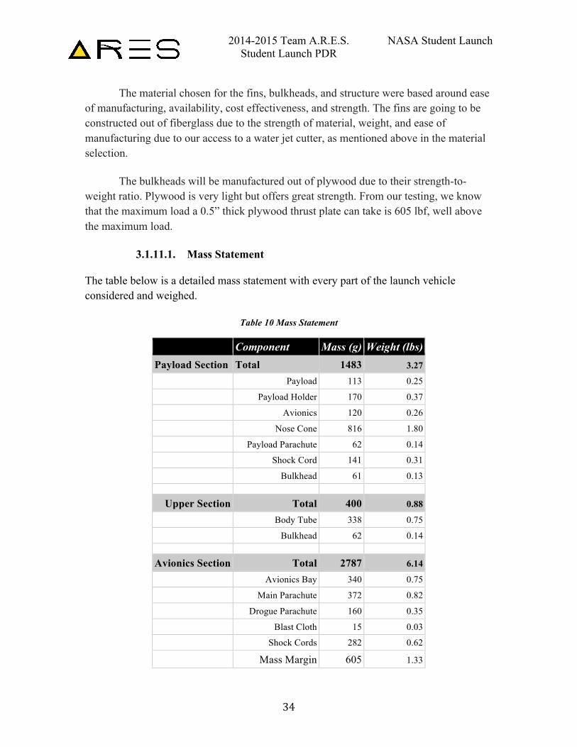
3.1.11.1. Mass Statement The table below is a detailed mass statement with every part of the launch vehicle considered and weighed.
Table 10 Mass Statement
Component Mass (g) Weight (lbs)
Payload Section Total 1483 3.27
Payload 113 0.25
Payload Holder 170 0.37
Avionics 120 0.26
Nose Cone 816 1.80
Payload Parachute 62 0.14
Shock Cord 141 0.31
Bulkhead 61 0.13
Upper Section Total 400 0.88
Body Tube 338 0.75
Bulkhead 62 0.14
Avionics Section Total 2787 6.14
Avionics Bay 340 0.75
Main Parachute 372 0.82
Drogue Parachute 160 0.35
Blast Cloth 15 0.03
Shock Cords 282 0.62
Mass Margin 605 1.33
2014-2015 Team A.R.E.S. NASA Student Launch Student Launch PDR
35
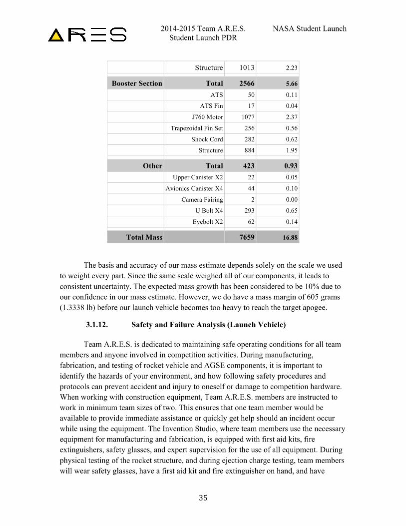
Structure 1013 2.23
Booster Section Total 2566 5.66
ATS 50 0.11
ATS Fin 17 0.04
J760 Motor 1077 2.37
Trapezoidal Fin Set 256 0.56
Shock Cord 282 0.62
Structure 884 1.95
Other Total 423 0.93
Upper Canister X2 22 0.05
Avionics Canister X4 44 0.10
Camera Fairing 2 0.00
U Bolt X4 293 0.65
Eyebolt X2 62 0.14
Total Mass
7659 16.88
The basis and accuracy of our mass estimate depends solely on the scale we used
to weight every part. Since the same scale weighed all of our components, it leads to consistent uncertainty. The expected mass growth has been considered to be 10% due to our confidence in our mass estimate. However, we do have a mass margin of 605 grams (1.3338 lb) before our launch vehicle becomes too heavy to reach the target apogee.
3.1.12. Safety and Failure Analysis (Launch Vehicle) Team A.R.E.S. is dedicated to maintaining safe operating conditions for all team members and anyone involved in competition activities. During manufacturing, fabrication, and testing of rocket vehicle and AGSE components, it is important to identify the hazards of your environment, and how following safety procedures and protocols can prevent accident and injury to oneself or damage to competition hardware. When working with construction equipment, Team A.R.E.S. members are instructed to work in minimum team sizes of two. This ensures that one team member would be available to provide immediate assistance or quickly get help should an incident occur while using the equipment. The Invention Studio, where team members use the necessary equipment for manufacturing and fabrication, is equipped with first aid kits, fire extinguishers, safety glasses, and expert supervision for the use of all equipment. During physical testing of the rocket structure, and during ejection charge testing, team members will wear safety glasses, have a first aid kit and fire extinguisher on hand, and have
2014-2015 Team A.R.E.S. NASA Student Launch Student Launch PDR
36
licensed safety officials present. In order to use the machines, all team members have been briefed on the proper protocols and procedures of using the lab machines.
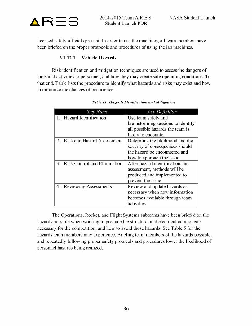
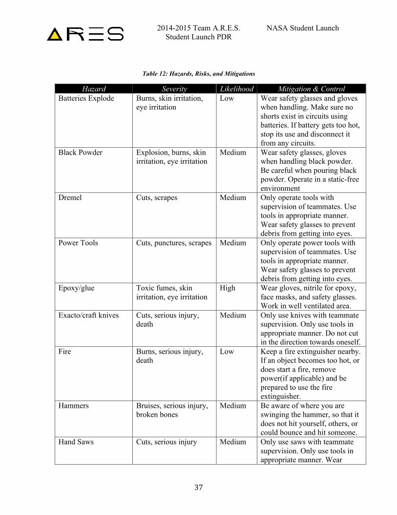
3.1.12.1. Vehicle Hazards Risk identification and mitigation techniques are used to assess the dangers of
tools and activities to personnel, and how they may create safe operating conditions. To that end, Table lists the procedure to identify what hazards and risks may exist and how to minimize the chances of occurrence.
Table 11: Hazards Identification and Mitigations
Step Name Step Definition 1. Hazard Identification Use team safety and
brainstorming sessions to identify all possible hazards the team is likely to encounter
2. Risk and Hazard Assessment Determine the likelihood and the severity of consequences should the hazard be encountered and how to approach the issue
3. Risk Control and Elimination After hazard identification and assessment, methods will be produced and implemented to prevent the issue
4. Reviewing Assessments Review and update hazards as necessary when new information becomes available through team activities
The Operations, Rocket, and Flight Systems subteams have been briefed on the
hazards possible when working to produce the structural and electrical components necessary for the competition, and how to avoid those hazards. See Table 5 for the hazards team members may experience. Briefing team members of the hazards possible, and repeatedly following proper safety protocols and procedures lower the likelihood of personnel hazards being realized.
2014-2015 Team A.R.E.S. NASA Student Launch Student Launch PDR
37
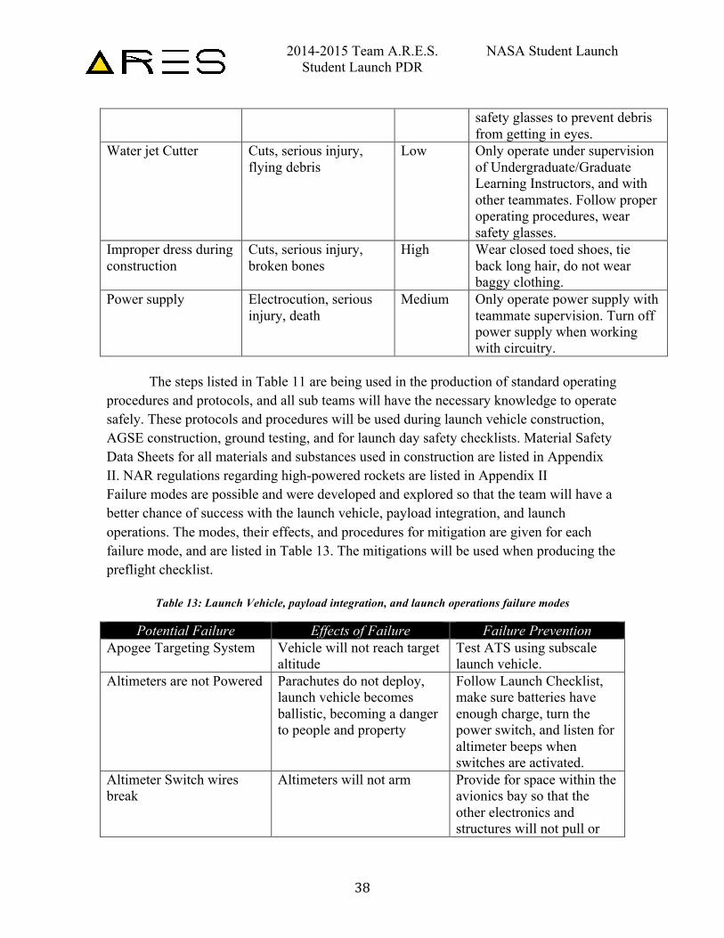
Table 12: Hazards, Risks, and Mitigations
Hazard Severity Likelihood Mitigation & Control Batteries Explode Burns, skin irritation,
eye irritation Low Wear safety glasses and gloves
when handling. Make sure no shorts exist in circuits using batteries. If battery gets too hot, stop its use and disconnect it from any circuits.
Black Powder Explosion, burns, skin irritation, eye irritation
Medium Wear safety glasses, gloves when handling black powder. Be careful when pouring black powder. Operate in a static-free environment
Dremel Cuts, scrapes Medium Only operate tools with supervision of teammates. Use tools in appropriate manner. Wear safety glasses to prevent debris from getting into eyes.
Power Tools Cuts, punctures, scrapes Medium Only operate power tools with supervision of teammates. Use tools in appropriate manner. Wear safety glasses to prevent debris from getting into eyes.
Epoxy/glue Toxic fumes, skin irritation, eye irritation
High Wear gloves, nitrile for epoxy, face masks, and safety glasses. Work in well ventilated area.
Exacto/craft knives Cuts, serious injury, death
Medium Only use knives with teammate supervision. Only use tools in appropriate manner. Do not cut in the direction towards oneself.
Fire Burns, serious injury, death
Low Keep a fire extinguisher nearby. If an object becomes too hot, or does start a fire, remove power(if applicable) and be prepared to use the fire extinguisher.
Hammers Bruises, serious injury, broken bones
Medium Be aware of where you are swinging the hammer, so that it does not hit yourself, others, or could bounce and hit someone.
Hand Saws Cuts, serious injury Medium Only use saws with teammate supervision. Only use tools in appropriate manner. Wear
2014-2015 Team A.R.E.S. NASA Student Launch Student Launch PDR
38
safety glasses to prevent debris from getting in eyes.
Water jet Cutter Cuts, serious injury, flying debris
Low Only operate under supervision of Undergraduate/Graduate Learning Instructors, and with other teammates. Follow proper operating procedures, wear safety glasses.
Improper dress during construction
Cuts, serious injury, broken bones
High Wear closed toed shoes, tie back long hair, do not wear baggy clothing.
Power supply Electrocution, serious injury, death
Medium Only operate power supply with teammate supervision. Turn off power supply when working with circuitry.
The steps listed in Table 11 are being used in the production of standard operating
procedures and protocols, and all sub teams will have the necessary knowledge to operate safely. These protocols and procedures will be used during launch vehicle construction, AGSE construction, ground testing, and for launch day safety checklists. Material Safety Data Sheets for all materials and substances used in construction are listed in Appendix II. NAR regulations regarding high-powered rockets are listed in Appendix II Failure modes are possible and were developed and explored so that the team will have a better chance of success with the launch vehicle, payload integration, and launch operations. The modes, their effects, and procedures for mitigation are given for each failure mode, and are listed in Table 13. The mitigations will be used when producing the preflight checklist.
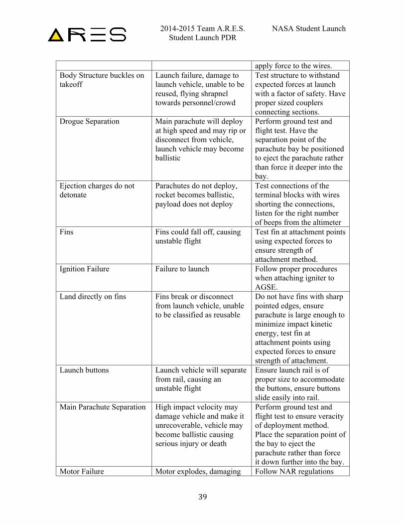
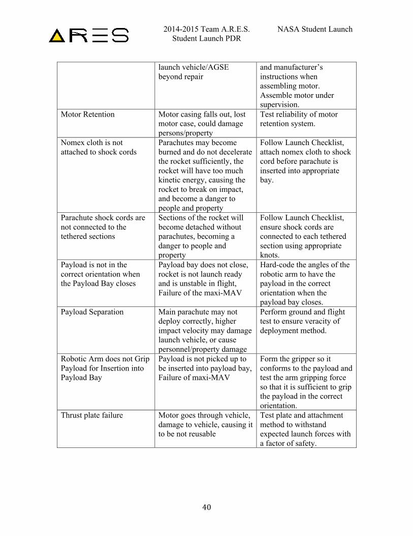
Table 13: Launch Vehicle, payload integration, and launch operations failure modes
Potential Failure Effects of Failure Failure Prevention Apogee Targeting System Vehicle will not reach target
altitude Test ATS using subscale launch vehicle.
Altimeters are not Powered Parachutes do not deploy, launch vehicle becomes ballistic, becoming a danger to people and property
Follow Launch Checklist, make sure batteries have enough charge, turn the power switch, and listen for altimeter beeps when switches are activated.
Altimeter Switch wires break
Altimeters will not arm Provide for space within the avionics bay so that the other electronics and structures will not pull or
2014-2015 Team A.R.E.S. NASA Student Launch Student Launch PDR
39
apply force to the wires. Body Structure buckles on takeoff
Launch failure, damage to launch vehicle, unable to be reused, flying shrapnel towards personnel/crowd
Test structure to withstand expected forces at launch with a factor of safety. Have proper sized couplers connecting sections.
Drogue Separation Main parachute will deploy at high speed and may rip or disconnect from vehicle, launch vehicle may become ballistic
Perform ground test and flight test. Have the separation point of the parachute bay be positioned to eject the parachute rather than force it deeper into the bay.
Ejection charges do not detonate
Parachutes do not deploy, rocket becomes ballistic, payload does not deploy
Test connections of the terminal blocks with wires shorting the connections, listen for the right number of beeps from the altimeter
Fins Fins could fall off, causing unstable flight
Test fin at attachment points using expected forces to ensure strength of attachment method.
Ignition Failure Failure to launch Follow proper procedures when attaching igniter to AGSE.
Land directly on fins Fins break or disconnect from launch vehicle, unable to be classified as reusable
Do not have fins with sharp pointed edges, ensure parachute is large enough to minimize impact kinetic energy, test fin at attachment points using expected forces to ensure strength of attachment.
Launch buttons Launch vehicle will separate from rail, causing an unstable flight
Ensure launch rail is of proper size to accommodate the buttons, ensure buttons slide easily into rail.
Main Parachute Separation High impact velocity may damage vehicle and make it unrecoverable, vehicle may become ballistic causing serious injury or death
Perform ground test and flight test to ensure veracity of deployment method. Place the separation point of the bay to eject the parachute rather than force it down further into the bay.
Motor Failure Motor explodes, damaging Follow NAR regulations
2014-2015 Team A.R.E.S. NASA Student Launch Student Launch PDR
40
launch vehicle/AGSE beyond repair
and manufacturer’s instructions when assembling motor. Assemble motor under supervision.
Motor Retention Motor casing falls out, lost motor case, could damage persons/property
Test reliability of motor retention system.
Nomex cloth is not attached to shock cords
Parachutes may become burned and do not decelerate the rocket sufficiently, the rocket will have too much kinetic energy, causing the rocket to break on impact, and become a danger to people and property
Follow Launch Checklist, attach nomex cloth to shock cord before parachute is inserted into appropriate bay.
Parachute shock cords are not connected to the tethered sections
Sections of the rocket will become detached without parachutes, becoming a danger to people and property
Follow Launch Checklist, ensure shock cords are connected to each tethered section using appropriate knots.
Payload is not in the correct orientation when the Payload Bay closes
Payload bay does not close, rocket is not launch ready and is unstable in flight, Failure of the maxi-MAV
Hard-code the angles of the robotic arm to have the payload in the correct orientation when the payload bay closes.
Payload Separation Main parachute may not deploy correctly, higher impact velocity may damage launch vehicle, or cause personnel/property damage
Perform ground and flight test to ensure veracity of deployment method.
Robotic Arm does not Grip Payload for Insertion into Payload Bay
Payload is not picked up to be inserted into payload bay, Failure of maxi-MAV
Form the gripper so it conforms to the payload and test the arm gripping force so that it is sufficient to grip the payload in the correct orientation.
Thrust plate failure Motor goes through vehicle, damage to vehicle, causing it to be not reusable
Test plate and attachment method to withstand expected launch forces with a factor of safety.
2014-2015 Team A.R.E.S. NASA Student Launch Student Launch PDR
41
3.1.12.2. Environmental Concerns
The rocket vehicle has several methods for which it can interact with its environment, and in turn, be affected by its environment. The rocket motor expels propellant at high velocity and temperature, and is capable of igniting any flammable materials near the launch pad. A fire extinguisher in close proximity and an angled steel deflector plate on the AGSE minimizes the possibility of a fire. The vehicle motor could explode, causing shrapnel to fly at people and property, and could cause a fire. After launch, the rocket accelerates upward and becomes a hazard to flying machines and animals, so the rocket will not be launched in the presence of birds or airplanes/helicopters in the immediate launch vicinity. Excessive windy conditions Clouds in the launch vicinity may obscure the launch vehicle as it climbs to apogee, which could make the vehicle a ballistic threat to people and property if the parachutes do not deploy. The pressure of the environment can affect how much thrust the rocket has, as the thrust is partially dependent on the pressure difference between ambient conditions and the pressure of the expelled propellant from the motor. Higher ambient pressure means less thrust, and lower ambient pressure increases thrust.
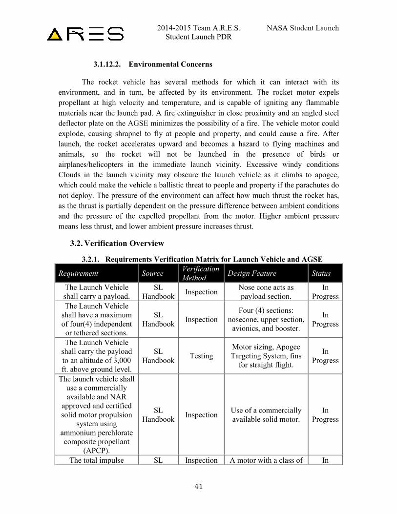
3.2. Verification Overview
3.2.1. Requirements Verification Matrix for Launch Vehicle and AGSE
Requirement Source Verification Method Design Feature Status
The Launch Vehicle shall carry a payload.
SL Handbook Inspection Nose cone acts as
payload section. In
Progress The Launch Vehicle
shall have a maximum of four(4) independent
or tethered sections.
SL Handbook Inspection
Four (4) sections: nosecone, upper section,
avionics, and booster.
In Progress
The Launch Vehicle shall carry the payload to an altitude of 3,000 ft. above ground level.
SL Handbook Testing
Motor sizing, Apogee Targeting System, fins
for straight flight.
In Progress
The launch vehicle shall use a commercially available and NAR
approved and certified solid motor propulsion
system using ammonium perchlorate composite propellant
(APCP).
SL Handbook Inspection Use of a commercially
available solid motor. In
Progress
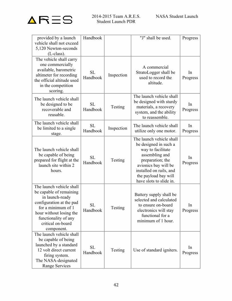
The total impulse SL Inspection A motor with a class of In
2014-2015 Team A.R.E.S. NASA Student Launch Student Launch PDR
42
provided by a launch vehicle shall not exceed 5,120 Newton-seconds
(L-class).
Handbook "J" shall be used. Progress
The vehicle shall carry one commercially
available, barometric altimeter for recording
the official altitude used in the competition
scoring.
SL Handbook Inspection
A commercial StratoLogger shall be
used to record the altitude.
In Progress
The launch vehicle shall be designed to be recoverable and
reusable.
SL Handbook Testing
The launch vehicle shall be designed with sturdy
materials, a recovery system, and the ability
to reassemble.
In Progress
The launch vehicle shall be limited to a single
stage.
SL Handbook Inspection The launch vehicle shall
utilize only one motor. In
Progress
The launch vehicle shall be capable of being
prepared for flight at the launch site within 2
hours.
SL Handbook Testing
The launch vehicle shall be designed in such a
way to facilitate assembling and preparation; the
avionics bay will be installed on rails, and the payload bay will have slots to slide in.
In Progress
The launch vehicle shall be capable of remaining
in launch-ready configuration at the pad
for a minimum of 1 hour without losing the
functionality of any critical on-board
component.
SL Handbook Testing
Battery supply shall be selected and calculated
to ensure on-board electronics will stay
functional for a minimum of 1 hour.
In Progress
The launch vehicle shall be capable of being
launched by a standard 12 volt direct current
firing system. The NASA-designated
Range Services
SL Handbook Testing Use of standard igniters. In
Progress
2014-2015 Team A.R.E.S. NASA Student Launch Student Launch PDR
43
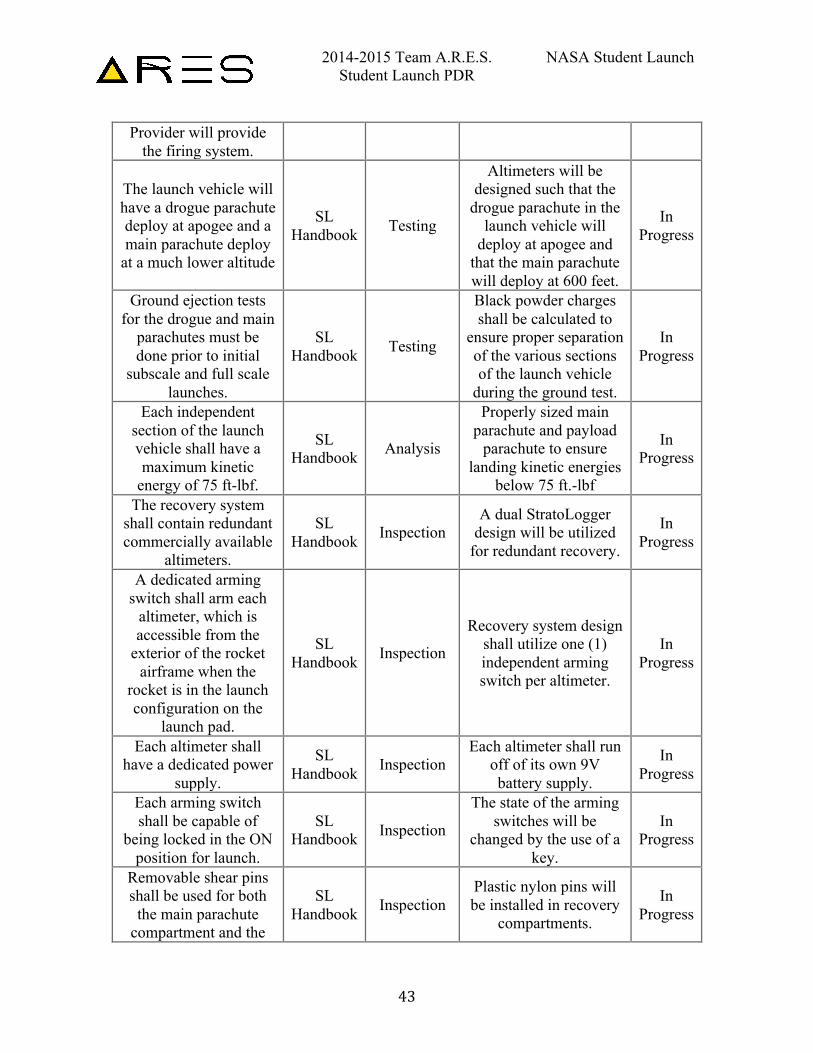
Provider will provide the firing system.
The launch vehicle will have a drogue parachute deploy at apogee and a main parachute deploy
at a much lower altitude
SL Handbook Testing
Altimeters will be designed such that the
drogue parachute in the launch vehicle will
deploy at apogee and that the main parachute will deploy at 600 feet.
In Progress
Ground ejection tests for the drogue and main
parachutes must be done prior to initial
subscale and full scale launches.
SL Handbook Testing
Black powder charges shall be calculated to
ensure proper separation of the various sections of the launch vehicle
during the ground test.
In Progress
Each independent section of the launch vehicle shall have a maximum kinetic
energy of 75 ft-lbf.
SL Handbook Analysis
Properly sized main parachute and payload
parachute to ensure landing kinetic energies
below 75 ft.-lbf
In Progress
The recovery system shall contain redundant commercially available
altimeters.
SL Handbook Inspection
A dual StratoLogger design will be utilized
for redundant recovery.
In Progress
A dedicated arming switch shall arm each
altimeter, which is accessible from the
exterior of the rocket airframe when the
rocket is in the launch configuration on the
launch pad.
SL Handbook Inspection
Recovery system design shall utilize one (1) independent arming switch per altimeter.
In Progress
Each altimeter shall have a dedicated power
supply.
SL Handbook Inspection
Each altimeter shall run off of its own 9V battery supply.
In Progress
Each arming switch shall be capable of
being locked in the ON position for launch.
SL Handbook Inspection
The state of the arming switches will be
changed by the use of a key.
In Progress
Removable shear pins shall be used for both
the main parachute compartment and the
SL Handbook Inspection
Plastic nylon pins will be installed in recovery
compartments.
In Progress
2014-2015 Team A.R.E.S. NASA Student Launch Student Launch PDR
44
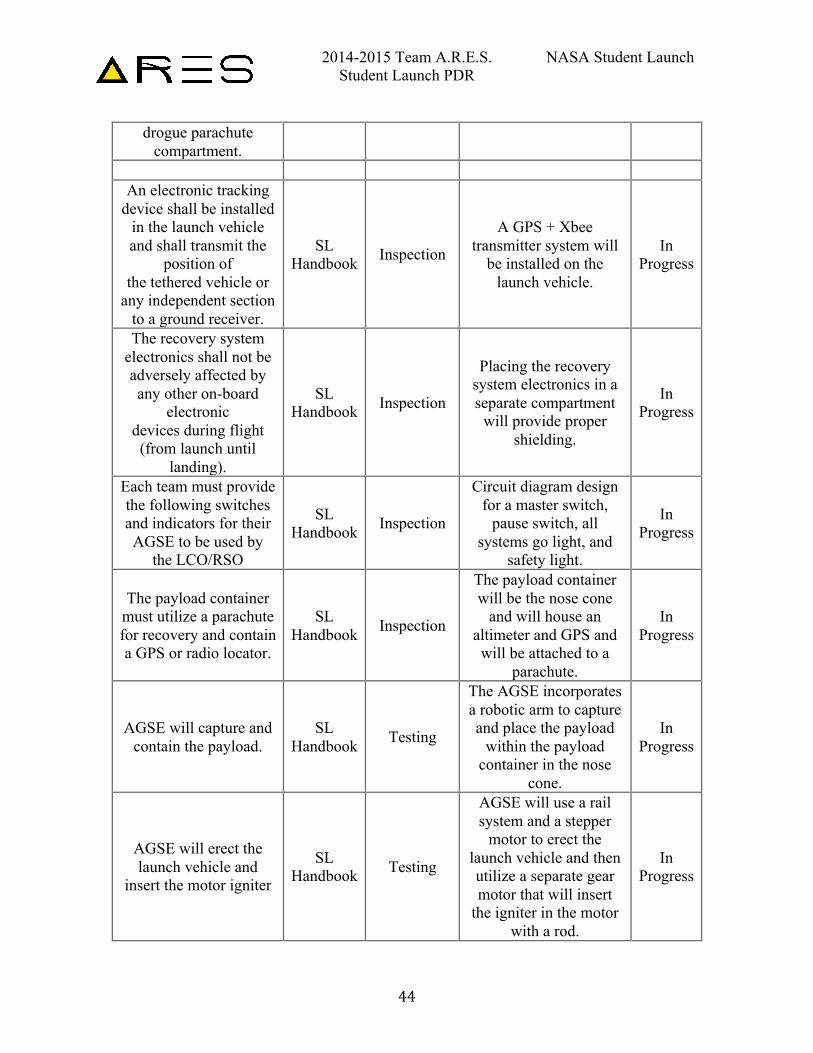
drogue parachute compartment.
An electronic tracking
device shall be installed in the launch vehicle and shall transmit the
position of the tethered vehicle or
any independent section to a ground receiver.
SL Handbook Inspection
A GPS + Xbee transmitter system will
be installed on the launch vehicle.
In Progress
The recovery system electronics shall not be adversely affected by any other on-board
electronic devices during flight (from launch until
landing).
SL Handbook Inspection
Placing the recovery system electronics in a separate compartment
will provide proper shielding.
In Progress
Each team must provide the following switches and indicators for their AGSE to be used by
the LCO/RSO
SL Handbook Inspection
Circuit diagram design for a master switch,
pause switch, all systems go light, and
safety light.
In Progress
The payload container must utilize a parachute for recovery and contain a GPS or radio locator.
SL Handbook Inspection
The payload container will be the nose cone
and will house an altimeter and GPS and will be attached to a
parachute.
In Progress
AGSE will capture and contain the payload.
SL Handbook Testing
The AGSE incorporates a robotic arm to capture and place the payload
within the payload container in the nose
cone.
In Progress
AGSE will erect the launch vehicle and
insert the motor igniter
SL Handbook Testing
AGSE will use a rail system and a stepper
motor to erect the launch vehicle and then utilize a separate gear motor that will insert
the igniter in the motor with a rod.
In Progress
2014-2015 Team A.R.E.S. NASA Student Launch Student Launch PDR
45
Each launch vehicle must have the space to contain a cylindrical
payload approximately 3/4
inch in diameter and 4.75 inches in length.
SL Handbook Inspection Payload Container In
Progress
The recovery system electrical circuits shall
be completely independent of any payload electrical
circuits.
SL Handbook Inspection
Payload electronics and recovery system
electronics shall be in separate compartments.
In Progress
The vehicle shall be flown in its fully
ballasted configuration during the full-scale test
flight.
SL Handbook Inspection
Weights shall be used as ballasts during the full-scale test flight and kept
the same for the competition flight.
In Progress
3.2.2. Structural Testing
Fins are used to balance the aerodynamic forces on a rocket to ensure a straight, stable flight. The location and shape of the fins determines the location of the center of pressure, and hence the stability margin. The trailing edge of the fins do not extend below the rocket body so the fins are not pointed so as to minimize any impact damage that may occur on landing.
The fins are made from 0.125 inch thick, G10 fiberglass sheets. There is a critical failure point that must be examined and tested to ensure that the fins do not break or become detached from the rocket body, causing the launch vehicle to become unstable in flight. The equation below was used to calculate the drag force acting on the fins.
𝐷 =12 ∗ 𝜌 ∗ 𝑉
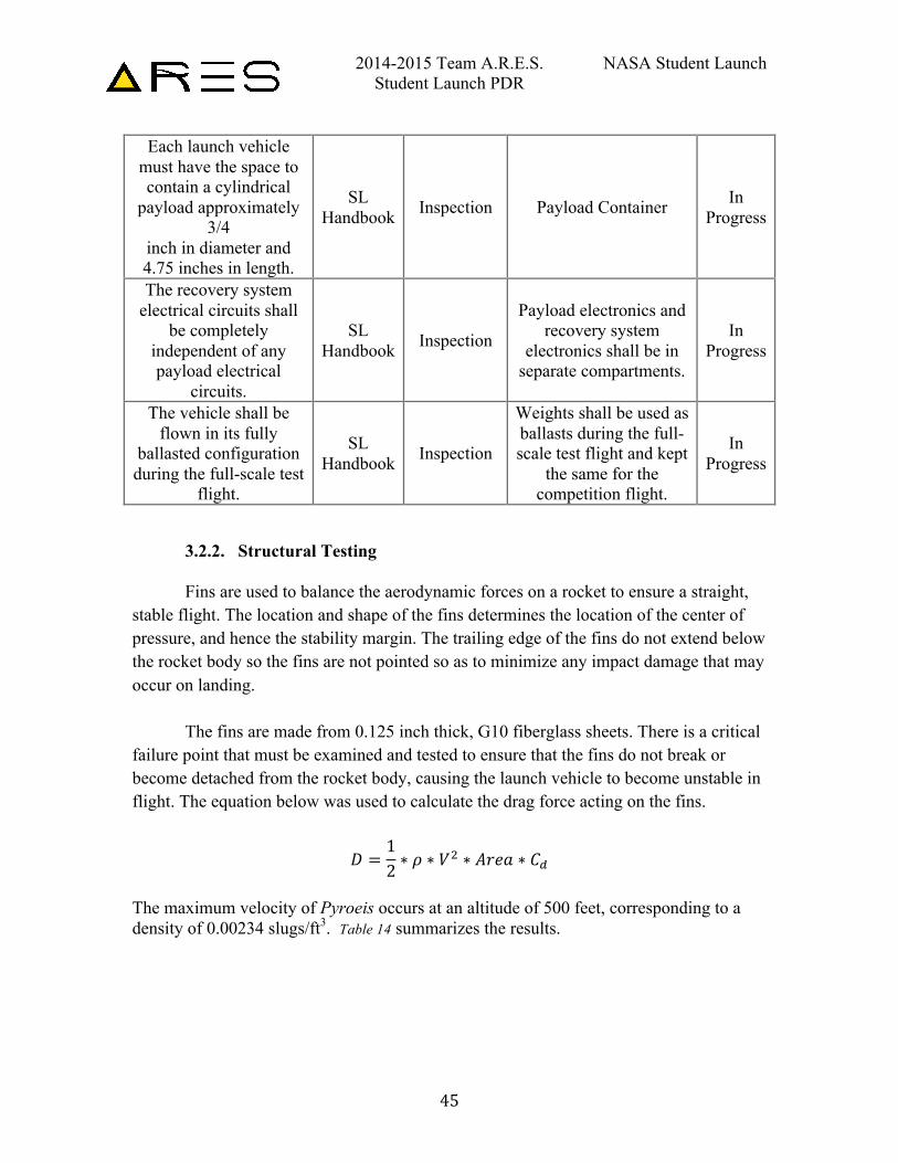
! ∗ 𝐴𝑟𝑒𝑎 ∗ 𝐶! The maximum velocity of Pyroeis occurs at an altitude of 500 feet, corresponding to a density of 0.00234 slugs/ft3. Table 14 summarizes the results.
2014-2015 Team A.R.E.S. NASA Student Launch Student Launch PDR
46
Table 14: Fin Drag Parameters and Calculation
Parameter Value
Cd 1.28
Air Density(slug/ft3) .00234
Vmax (ft/s) 489
Fin Area(ft2) .0026
Drag(lbf) 0.93
3.2.2.1. Fin Static Loading Test
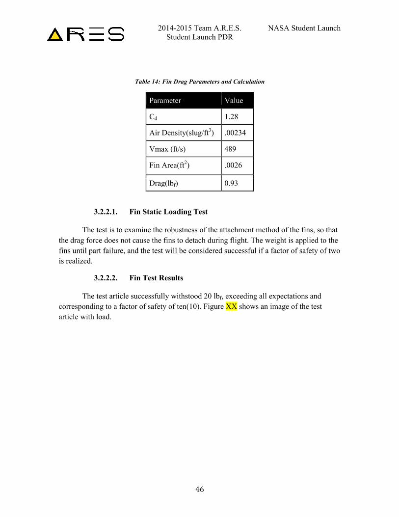
The test is to examine the robustness of the attachment method of the fins, so that the drag force does not cause the fins to detach during flight. The weight is applied to the fins until part failure, and the test will be considered successful if a factor of safety of two is realized.
3.2.2.2. Fin Test Results
The test article successfully withstood 20 lbf, exceeding all expectations and corresponding to a factor of safety of ten(10). Figure XX shows an image of the test article with load.
2014-2015 Team A.R.E.S. NASA Student Launch Student Launch PDR
47
Figure 22: Fin Test Jig and Test Article
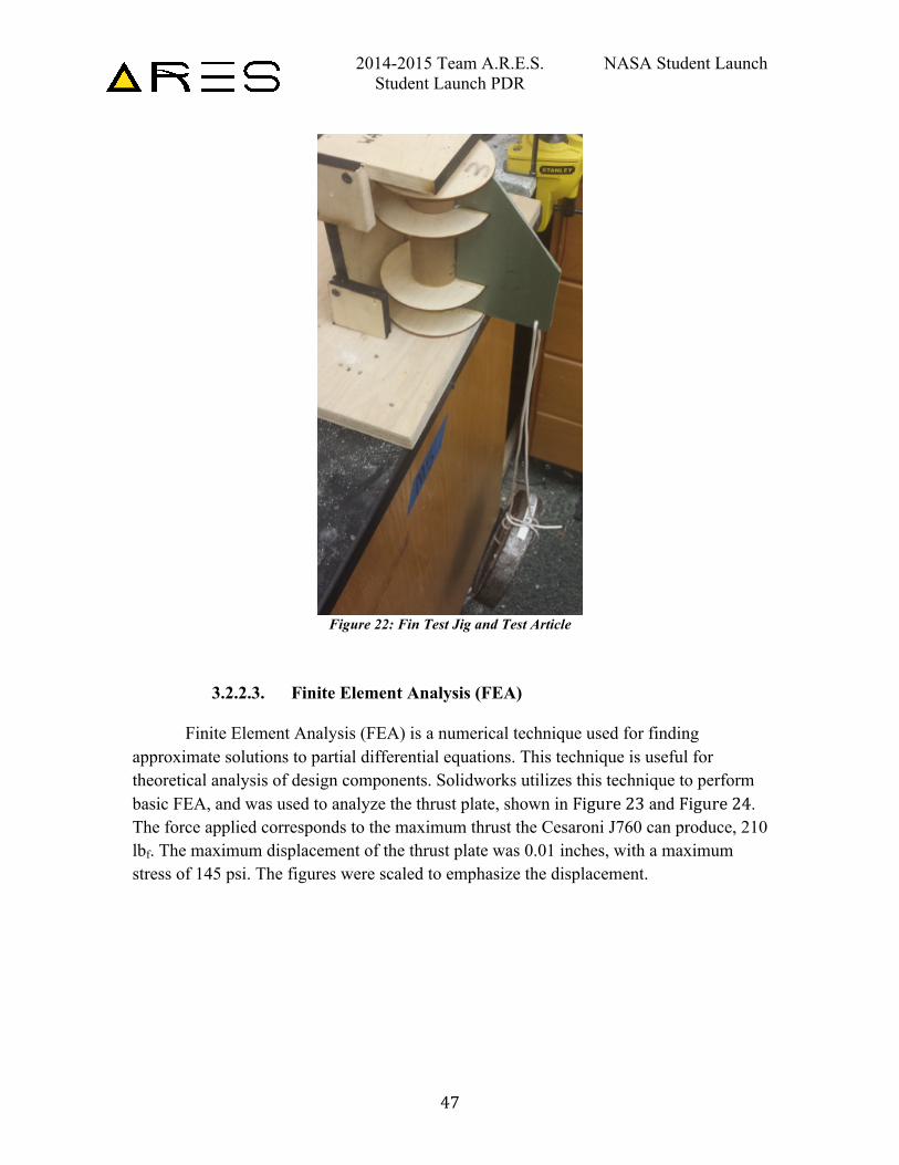
3.2.2.3. Finite Element Analysis (FEA) Finite Element Analysis (FEA) is a numerical technique used for finding
approximate solutions to partial differential equations. This technique is useful for theoretical analysis of design components. Solidworks utilizes this technique to perform basic FEA, and was used to analyze the thrust plate, shown in Figure 23 and Figure 24. The force applied corresponds to the maximum thrust the Cesaroni J760 can produce, 210 lbf. The maximum displacement of the thrust plate was 0.01 inches, with a maximum stress of 145 psi. The figures were scaled to emphasize the displacement.
2014-2015 Team A.R.E.S. NASA Student Launch Student Launch PDR
48
Figure 23: Bottom View of Thrust Plate FEA
Figure 24: Top View of Thrust Plate FEA
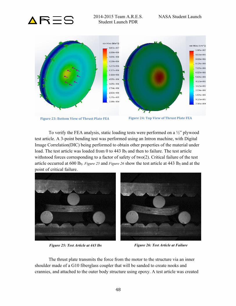
To verify the FEA analysis, static loading tests were performed on a ½” plywood
test article. A 3-point bending test was performed using an Intron machine, with Digital Image Correlation(DIC) being performed to obtain other properties of the material under load. The test article was loaded from 0 to 443 lbf and then to failure. The test article withstood forces corresponding to a factor of safety of two(2). Critical failure of the test article occurred at 600 lbf. Figure 25 and Figure 26 show the test article at 443 lbf and at the point of critical failure.
Figure 25: Test Article at 443 lbs
Figure 26: Test Article at Failure
The thrust plate transmits the force from the motor to the structure via an inner
shoulder made of a G10 fiberglass coupler that will be sanded to create nooks and crannies, and attached to the outer body structure using epoxy. A test article was created
2014-2015 Team A.R.E.S. NASA Student Launch Student Launch PDR
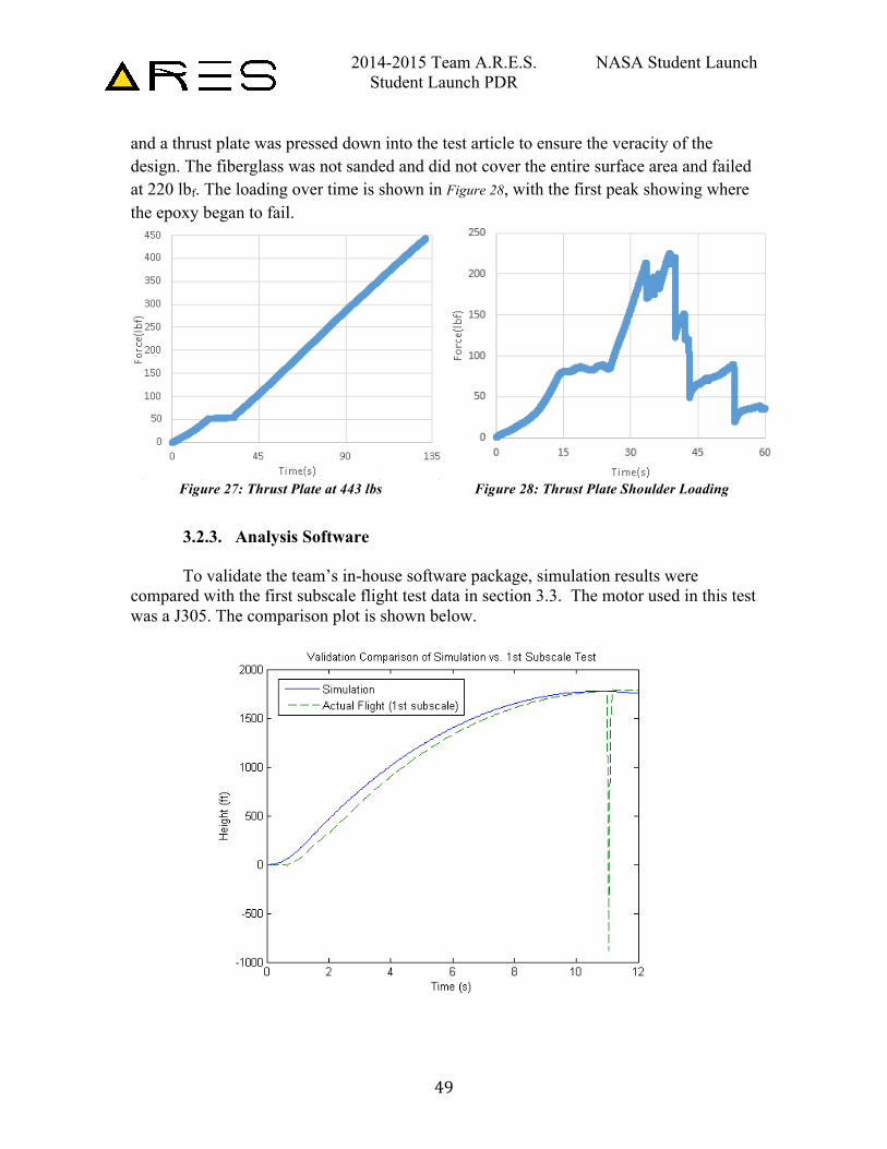
49
and a thrust plate was pressed down into the test article to ensure the veracity of the design. The fiberglass was not sanded and did not cover the entire surface area and failed at 220 lbf. The loading over time is shown in Figure 28, with the first peak showing where the epoxy began to fail.
Figure 27: Thrust Plate at 443 lbs
Figure 28: Thrust Plate Shoulder Loading
3.2.3. Analysis Software To validate the team’s in-house software package, simulation results were
compared with the first subscale flight test data in section 3.3. The motor used in this test was a J305. The comparison plot is shown below.
2014-2015 Team A.R.E.S. NASA Student Launch Student Launch PDR
50
The two curves are seen to match well in terms of slope and apogee. Notable differences are the 100-foot difference in altitude from second to second during the ascent, which is most likely caused by slight differences in how “zero time” is defined between flight and simulation. Also, the apparent massive “dip” in the flight data is the result of the altimeter-marking apogee, and can therefore be safely ignored.
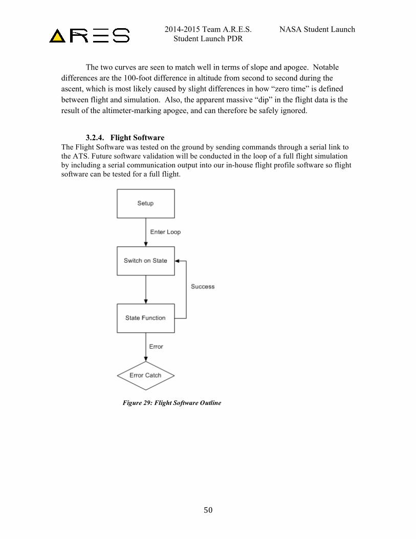
3.2.4. Flight Software The Flight Software was tested on the ground by sending commands through a serial link to the ATS. Future software validation will be conducted in the loop of a full flight simulation by including a serial communication output into our in-house flight profile software so flight software can be tested for a full flight.
Figure 29: Flight Software Outline
2014-2015 Team A.R.E.S. NASA Student Launch Student Launch PDR
51
3.3. Subscale Flight and Results
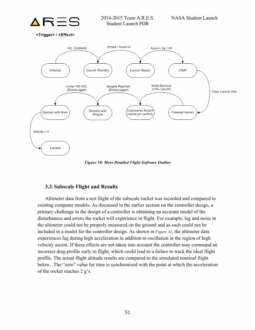
Altimeter data from a test flight of the subscale rocket was recorded and compared to existing computer models. As discussed in the earlier section on the controller design, a primary challenge in the design of a controller is obtaining an accurate model of the disturbances and errors the rocket will experience in flight. For example, lag and noise in the altimeter could not be properly measured on the ground and as such could not be included in a model for the controller design. As shown in Figure 31, the altimeter data experiences lag during high acceleration in addition to oscillation in the region of high velocity ascent. If these effects are not taken into account the controller may command an incorrect drag profile early in flight, which could lead to a failure to track the ideal flight profile. The actual flight altitude results are compared to the simulated nominal flight below. The “zero” value for time is synchronized with the point at which the acceleration of the rocket reaches 2 g’s.
Figure 30: More Detailed Flight Software Outline
2014-2015 Team A.R.E.S. NASA Student Launch Student Launch PDR
52
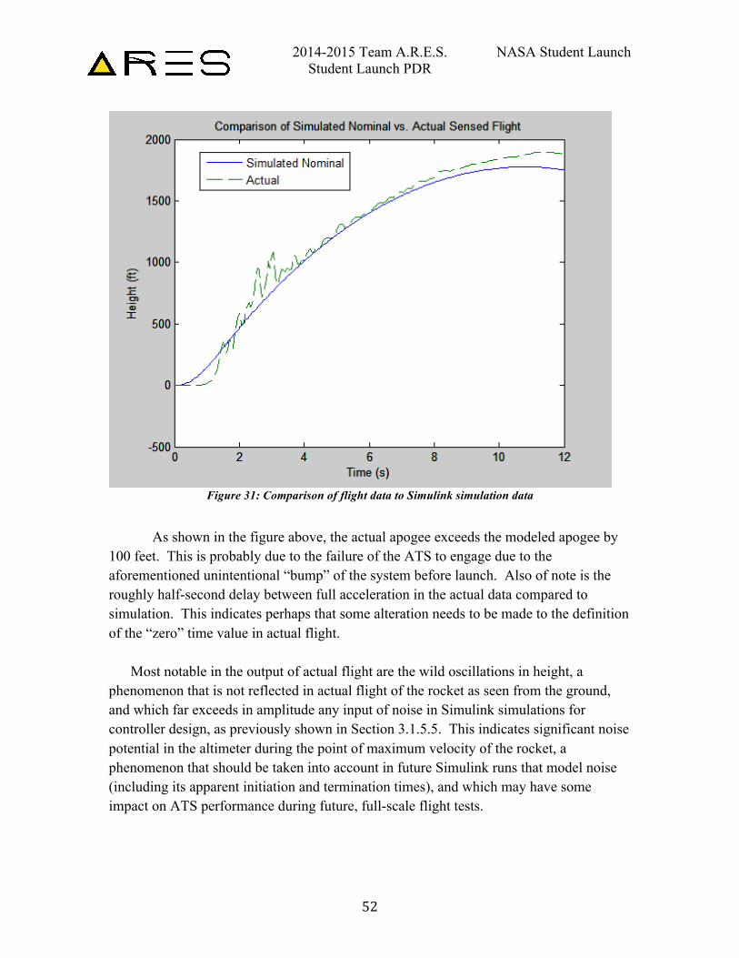
Figure 31: Comparison of flight data to Simulink simulation data
As shown in the figure above, the actual apogee exceeds the modeled apogee by
100 feet. This is probably due to the failure of the ATS to engage due to the aforementioned unintentional “bump” of the system before launch. Also of note is the roughly half-second delay between full acceleration in the actual data compared to simulation. This indicates perhaps that some alteration needs to be made to the definition of the “zero” time value in actual flight.
Most notable in the output of actual flight are the wild oscillations in height, a phenomenon that is not reflected in actual flight of the rocket as seen from the ground, and which far exceeds in amplitude any input of noise in Simulink simulations for controller design, as previously shown in Section 3.1.5.5. This indicates significant noise potential in the altimeter during the point of maximum velocity of the rocket, a phenomenon that should be taken into account in future Simulink runs that model noise (including its apparent initiation and termination times), and which may have some impact on ATS performance during future, full-scale flight tests.
2014-2015 Team A.R.E.S. NASA Student Launch Student Launch PDR
53
3.4. Recovery Subsystem
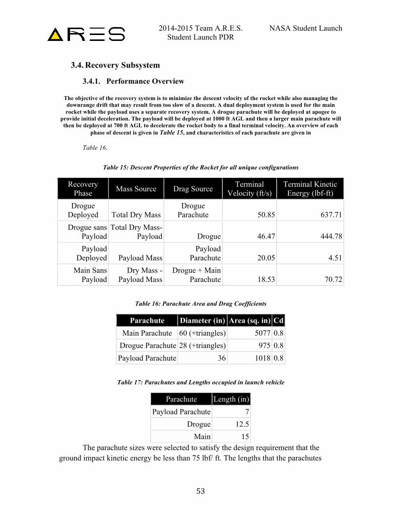
3.4.1. Performance Overview
The objective of the recovery system is to minimize the descent velocity of the rocket while also managing the downrange drift that may result from too slow of a descent. A dual deployment system is used for the main rocket while the payload uses a separate recovery system. A drogue parachute will be deployed at apogee to
provide initial deceleration. The payload will be deployed at 1000 ft AGL and then a larger main parachute will then be deployed at 700 ft AGL to decelerate the rocket body to a final terminal velocity. An overview of each
phase of descent is given in Table 15, and characteristics of each parachute are given in
Table 16.
Table 15: Descent Properties of the Rocket for all unique configurations
Recovery Phase Mass Source Drag Source Terminal
Velocity (ft/s) Terminal Kinetic Energy (lbf-ft)
Drogue Deployed Total Dry Mass
Drogue Parachute 50.85 637.71
Drogue sans Payload
Total Dry Mass-Payload Drogue 46.47 444.78
Payload Deployed Payload Mass
Payload Parachute 20.05 4.51
Main Sans Payload
Dry Mass - Payload Mass
Drogue + Main Parachute 18.53 70.72
Table 16: Parachute Area and Drag Coefficients
Parachute Diameter (in) Area (sq. in) Cd Main Parachute 60 (+triangles) 5077 0.8
Drogue Parachute 28 (+triangles) 975 0.8 Payload Parachute 36 1018 0.8
Table 17: Parachutes and Lengths occupied in launch vehicle
Parachute Length (in) Payload Parachute 7
Drogue 12.5 Main 15
The parachute sizes were selected to satisfy the design requirement that the ground impact kinetic energy be less than 75 lbf/ ft. The lengths that the parachutes
2014-2015 Team A.R.E.S. NASA Student Launch Student Launch PDR
54
occupied in the rocket in Table 3.3.1.3 were also taken into consideration depending on the space available in the rocket. In order to find the terminal velocity of the rocket after the payload had been deployed, the drag force and weight at each phase were calculated and an equilibrium state was assumed. Drag force is given by:
FD = .5v2CDA where is the density of air, 1.225 kg/m, at 59 degrees Fahrenheit, A is the area of the parachute, and CD is the parachute coefficient of drag. Solving for velocity,
v = (2FD)/(CDA) And including acceleration due to gravity
FD = ma = mg Kinetic energy is then given by
E = 1/2mv2 where m is the mass of the rocket for a given descent phase, and g is the acceleration of gravity. Substituting Equation 3.3.1.2 for velocity then gives:
E=1/2m(2FD)/(CDA) The terminal kinetic energy of the rocket, excluding the payload which was deployed at 1000 ft, is then given by 39.54 lbf-ft, which is within the design constraint of 75 lbf-ft.
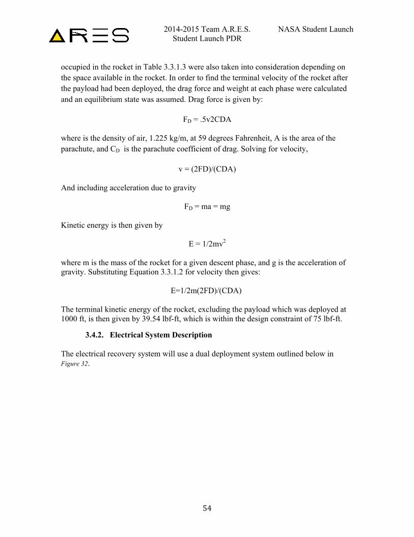
3.4.2. Electrical System Description The electrical recovery system will use a dual deployment system outlined below in Figure 32.
2014-2015 Team A.R.E.S. NASA Student Launch Student Launch PDR
55
Figure 32: Recovery Electrical System
3.5. Mission Performance Predictions
3.5.1. Mission Performance Prediction
Our target apogee is 3000 ft per design requirement, however, the rocket will utilize a motor that will overshoot this target altitude. The overshoot is necessary in order for the ATS, described above, to produce enough drag such that the rocket achieves the target altitude.
3.5.2. Simulation Software
3.5.2.1. OpenRocket
OpenRocket was chosen the software to simulate a flight profile for the rocket without active control. The OpenRocket results were also used as a reference when designing in-house simulation software discussed in section 3.4.2.2. While OpenRocket lacked the ability to simulate the effect of the ATS, the software was used to determine flight performance without the ATS while also serving as a guideline as to whether the MATLAB code was functioning correctly.
3.5.2.2. MATLAB and Simulink
Please refer to section 3.1.5.4 for a discussion on the MATLAB and Simulink simulation software.
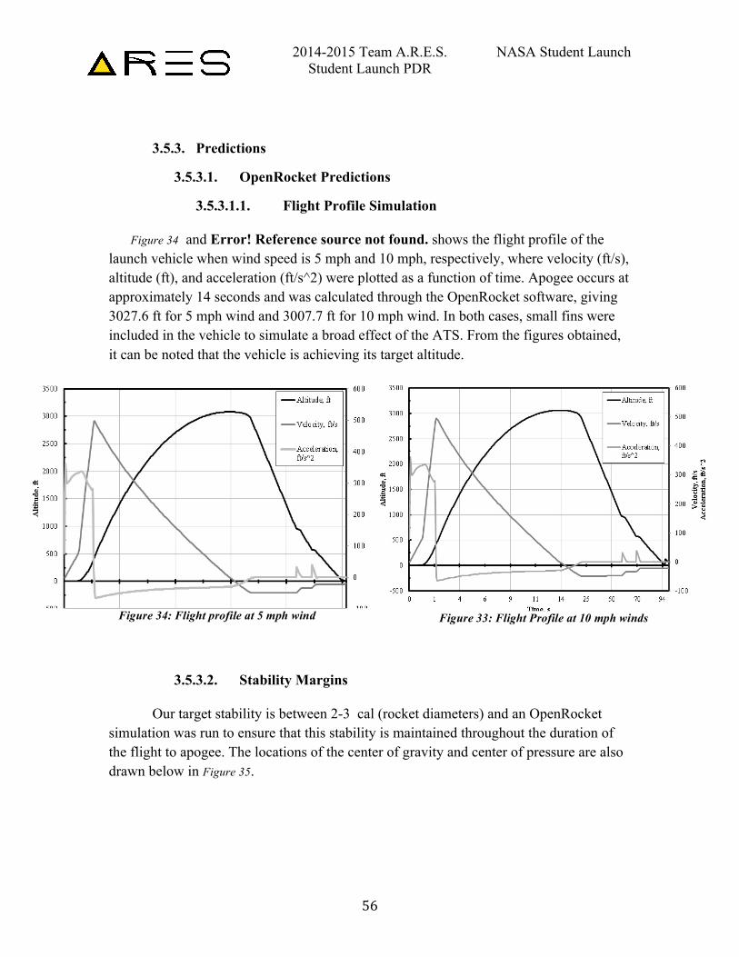
2014-2015 Team A.R.E.S. NASA Student Launch Student Launch PDR
56
3.5.3. Predictions
3.5.3.1. OpenRocket Predictions
3.5.3.1.1. Flight Profile Simulation
Figure 34 and Error! Reference source not found. shows the flight profile of the launch vehicle when wind speed is 5 mph and 10 mph, respectively, where velocity (ft/s), altitude (ft), and acceleration (ft/s^2) were plotted as a function of time. Apogee occurs at approximately 14 seconds and was calculated through the OpenRocket software, giving 3027.6 ft for 5 mph wind and 3007.7 ft for 10 mph wind. In both cases, small fins were included in the vehicle to simulate a broad effect of the ATS. From the figures obtained, it can be noted that the vehicle is achieving its target altitude.
3.5.3.2. Stability Margins
Our target stability is between 2-3 cal (rocket diameters) and an OpenRocket simulation was run to ensure that this stability is maintained throughout the duration of the flight to apogee. The locations of the center of gravity and center of pressure are also drawn below in Figure 35.
Figure 34: Flight profile at 5 mph wind Figure 33: Flight Profile at 10 mph winds
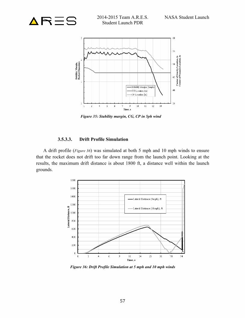
2014-2015 Team A.R.E.S. NASA Student Launch Student Launch PDR
57
3.5.3.3. Drift Profile Simulation
A drift profile (Figure 36) was simulated at both 5 mph and 10 mph winds to ensure that the rocket does not drift too far down range from the launch point. Looking at the results, the maximum drift distance is about 1800 ft, a distance well within the launch grounds.
Figure 36: Drift Profile Simulation at 5 mph and 10 mph winds
Figure 35: Stability margin, CG, CP in 5ph wind
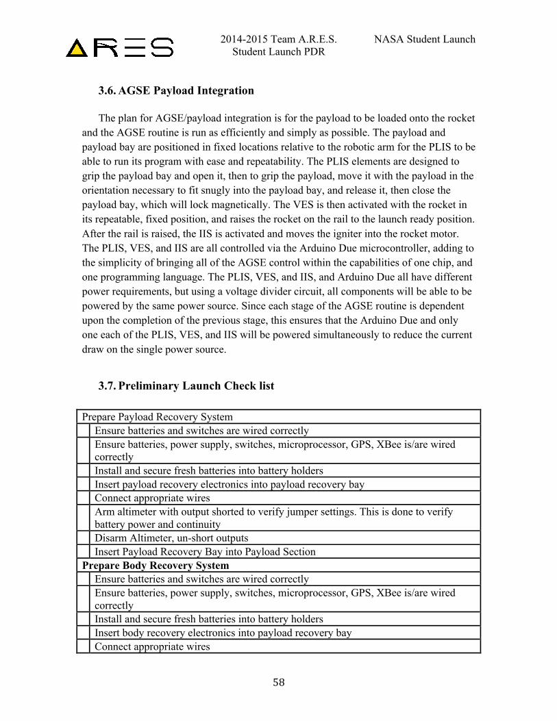
2014-2015 Team A.R.E.S. NASA Student Launch Student Launch PDR
58
3.6. AGSE Payload Integration The plan for AGSE/payload integration is for the payload to be loaded onto the rocket
and the AGSE routine is run as efficiently and simply as possible. The payload and payload bay are positioned in fixed locations relative to the robotic arm for the PLIS to be able to run its program with ease and repeatability. The PLIS elements are designed to grip the payload bay and open it, then to grip the payload, move it with the payload in the orientation necessary to fit snugly into the payload bay, and release it, then close the payload bay, which will lock magnetically. The VES is then activated with the rocket in its repeatable, fixed position, and raises the rocket on the rail to the launch ready position. After the rail is raised, the IIS is activated and moves the igniter into the rocket motor. The PLIS, VES, and IIS are all controlled via the Arduino Due microcontroller, adding to the simplicity of bringing all of the AGSE control within the capabilities of one chip, and one programming language. The PLIS, VES, and IIS, and Arduino Due all have different power requirements, but using a voltage divider circuit, all components will be able to be powered by the same power source. Since each stage of the AGSE routine is dependent upon the completion of the previous stage, this ensures that the Arduino Due and only one each of the PLIS, VES, and IIS will be powered simultaneously to reduce the current draw on the single power source.
3.7. Preliminary Launch Check list Prepare Payload Recovery System Ensure batteries and switches are wired correctly Ensure batteries, power supply, switches, microprocessor, GPS, XBee is/are wired
correctly Install and secure fresh batteries into battery holders Insert payload recovery electronics into payload recovery bay Connect appropriate wires Arm altimeter with output shorted to verify jumper settings. This is done to verify
battery power and continuity Disarm Altimeter, un-short outputs Insert Payload Recovery Bay into Payload Section Prepare Body Recovery System Ensure batteries and switches are wired correctly Ensure batteries, power supply, switches, microprocessor, GPS, XBee is/are wired
correctly Install and secure fresh batteries into battery holders Insert body recovery electronics into payload recovery bay Connect appropriate wires
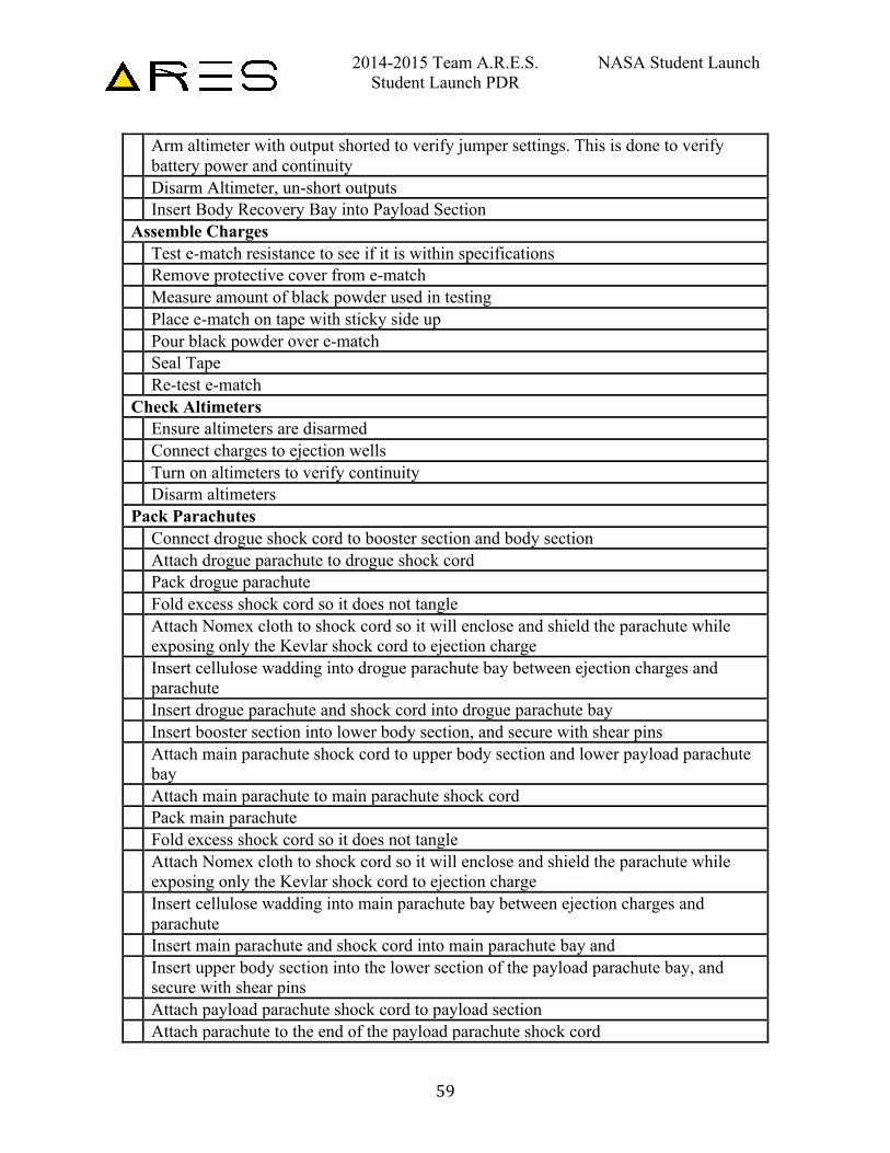
2014-2015 Team A.R.E.S. NASA Student Launch Student Launch PDR
59
Arm altimeter with output shorted to verify jumper settings. This is done to verify battery power and continuity
Disarm Altimeter, un-short outputs Insert Body Recovery Bay into Payload Section Assemble Charges Test e-match resistance to see if it is within specifications Remove protective cover from e-match Measure amount of black powder used in testing Place e-match on tape with sticky side up Pour black powder over e-match Seal Tape Re-test e-match Check Altimeters Ensure altimeters are disarmed Connect charges to ejection wells Turn on altimeters to verify continuity Disarm altimeters Pack Parachutes Connect drogue shock cord to booster section and body section Attach drogue parachute to drogue shock cord Pack drogue parachute Fold excess shock cord so it does not tangle Attach Nomex cloth to shock cord so it will enclose and shield the parachute while
exposing only the Kevlar shock cord to ejection charge Insert cellulose wadding into drogue parachute bay between ejection charges and
parachute Insert drogue parachute and shock cord into drogue parachute bay Insert booster section into lower body section, and secure with shear pins Attach main parachute shock cord to upper body section and lower payload parachute
bay Attach main parachute to main parachute shock cord Pack main parachute Fold excess shock cord so it does not tangle Attach Nomex cloth to shock cord so it will enclose and shield the parachute while
exposing only the Kevlar shock cord to ejection charge Insert cellulose wadding into main parachute bay between ejection charges and
parachute Insert main parachute and shock cord into main parachute bay and Insert upper body section into the lower section of the payload parachute bay, and
secure with shear pins Attach payload parachute shock cord to payload section Attach parachute to the end of the payload parachute shock cord
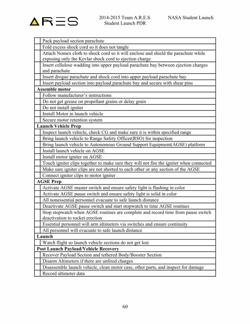
2014-2015 Team A.R.E.S. NASA Student Launch Student Launch PDR
60
Pack payload section parachute Fold excess shock cord so it does not tangle Attach Nomex cloth to shock cord so it will enclose and shield the parachute while
exposing only the Kevlar shock cord to ejection charge Insert cellulose wadding into upper payload parachute bay between ejection charges
and parachute Insert drogue parachute and shock cord into upper payload parachute bay Insert payload section into payload parachute bay and secure with shear pins Assemble motor Follow manufacturer’s instructions Do not get grease on propellant grains or delay grain Do not install igniter Install Motor in launch vehicle Secure motor retention system Launch Vehicle Prep Inspect launch vehicle, check CG and make sure it is within specified range Bring launch vehicle to Range Safety Officer(RSO) for inspection Bring launch vehicle to Autonomous Ground Support Equipment(AGSE) platform Install launch vehicle on AGSE Install motor igniter on AGSE Touch igniter clips together to make sure they will not fire the igniter when connected Make sure igniter clips are not shorted to each other or any section of the AGSE Connect igniter clips to motor igniter AGSE Prep Activate AGSE master switch and ensure safety light is flashing in color Activate AGSE pause switch and ensure safety light is solid in color All nonessential personnel evacuate to safe launch distance Deactivate AGSE pause switch and start stopwatch to time AGSE routines Stop stopwatch when AGSE routines are complete and record time from pause switch
deactivation to rocket erection Essential personnel will arm altimeters via switches and ensure continuity All personnel will evacuate to safe launch distance Launch Watch flight so launch vehicle sections do not get lost Post Launch Payload/Vehicle Recovery Recover Payload Section and tethered Body/Booster Section Disarm Altimeters if there are unfired charges Disassemble launch vehicle, clean motor case, other parts, and inspect for damage Record altimeter data
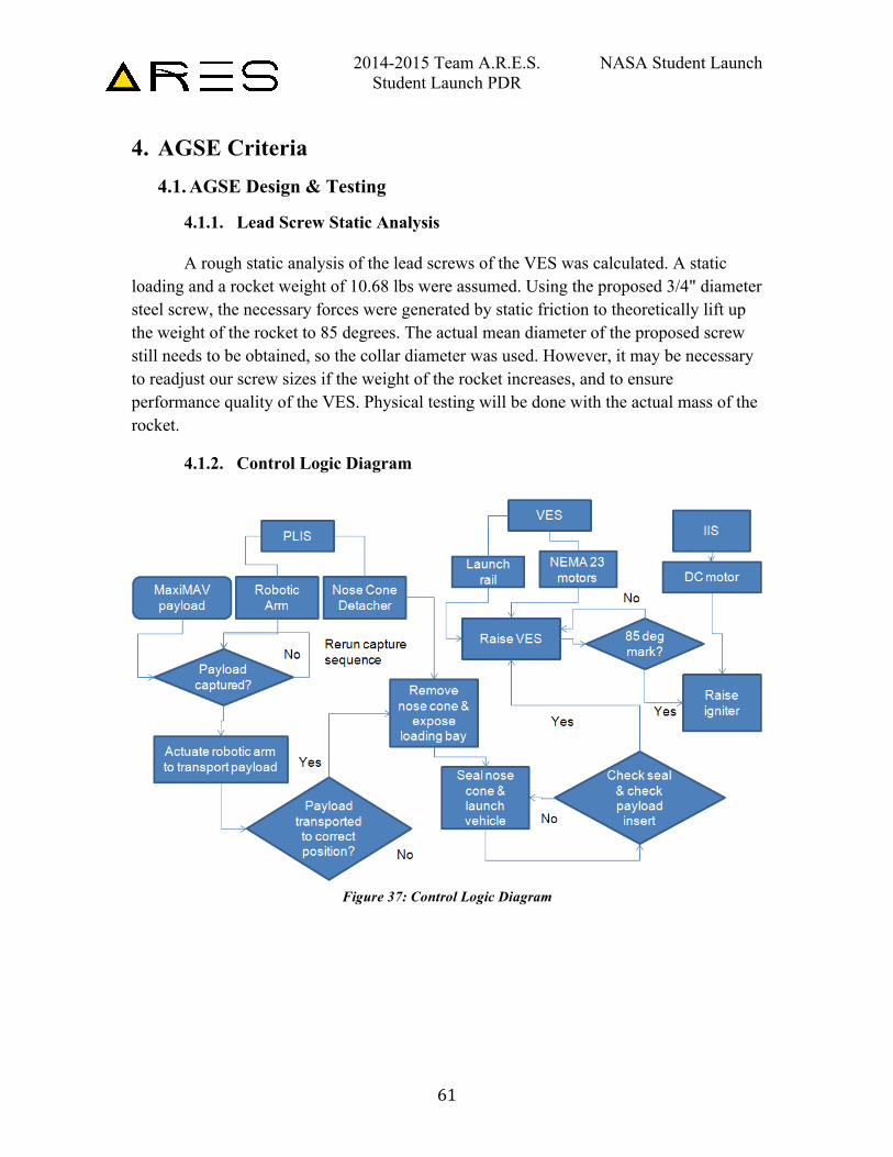
2014-2015 Team A.R.E.S. NASA Student Launch Student Launch PDR
61
4. AGSE Criteria 4.1. AGSE Design & Testing
4.1.1. Lead Screw Static Analysis
A rough static analysis of the lead screws of the VES was calculated. A static loading and a rocket weight of 10.68 lbs were assumed. Using the proposed 3/4" diameter steel screw, the necessary forces were generated by static friction to theoretically lift up the weight of the rocket to 85 degrees. The actual mean diameter of the proposed screw still needs to be obtained, so the collar diameter was used. However, it may be necessary to readjust our screw sizes if the weight of the rocket increases, and to ensure performance quality of the VES. Physical testing will be done with the actual mass of the rocket.
4.1.2. Control Logic Diagram
Figure 37: Control Logic Diagram
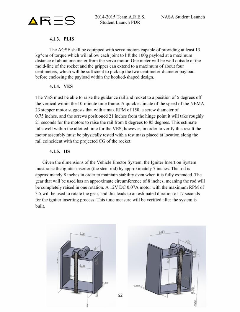
2014-2015 Team A.R.E.S. NASA Student Launch Student Launch PDR
62
4.1.3. PLIS The AGSE shall be equipped with servo motors capable of providing at least 13
kg*cm of torque which will allow each joint to lift the 100g payload at a maximum distance of about one meter from the servo motor. One meter will be well outside of the mold-line of the rocket and the gripper can extend to a maximum of about four centimeters, which will be sufficient to pick up the two centimeter-diameter payload before enclosing the payload within the hooked-shaped design.
4.1.4. VES The VES must be able to raise the guidance rail and rocket to a position of 5 degrees off the vertical within the 10-minute time frame. A quick estimate of the speed of the NEMA 23 stepper motor suggests that with a max RPM of 150, a screw diameter of 0.75 inches, and the screws positioned 21 inches from the hinge point it will take roughly 21 seconds for the motors to raise the rail from 0 degrees to 85 degrees. This estimate falls well within the allotted time for the VES; however, in order to verify this result the motor assembly must be physically tested with a test mass placed at location along the rail coincident with the projected CG of the rocket.
4.1.5. IIS
Given the dimensions of the Vehicle Erector System, the Igniter Insertion System must raise the igniter inserter (the steel rod) by approximately 7 inches. The rod is approximately 8 inches in order to maintain stability even when it is fully extended. The gear that will be used has an approximate circumference of 8 inches, meaning the rod will be completely raised in one rotation. A 12V DC 0.07A motor with the maximum RPM of 3.5 will be used to rotate the gear, and this leads to an estimated duration of 17 seconds for the igniter inserting process. This time measure will be verified after the system is built.
2014-2015 Team A.R.E.S. NASA Student Launch Student Launch PDR
63
4.2. AGSE Approach to Workmanship
The AGSE team is dedicated to quality workmanship to ensure mission success. To make this happen, the team is focused on cost efficiency, whether it is of design, materials, manufacturing, or time. For design, the approach is to create a working design with the bare minimum of functionality necessary to complete the mission, as this will minimize the mass of components and complexity for the equipment necessary for a Mars Ascent Vehicle. (MAV) The cost efficiency of materials is in their ease of manufacturability, machinability, and obtainability. This multifaceted approach to workmanship allows for quality production in a timely fashion.
4.2.1. AGSE Testing Plans
4.2.1.1. Component Testing
Component testing of the PLIS, VES, and IIS will take place during the completion of each part prior to the integration of the whole station to ensure that each component can achieve its respective tasks. Specifically, the PLIS needs to correctly capture & place the payload in the payload chamber in the rocket nose cone, the IIS will have to place the igniter into the rocket motor cavity, and the VES will need to raise the rocket to the required angle of 85 degrees. The success or failure during component testing can be determined through observation and through additional measurements to ensure specified requirements are made.
4.2.1.2. Functional Testing,
Functional testing of the programs for each component will take place along with each component testing trial. For example, the software component controlling the VES will be tested along with VES component testing procedure. After the final integration of the system and program, black-box testing of the actual code will be carried out by actually executing the program controlling the AGSE over multiple trials. The trials will cover all cases and modes that the AGSE can possibly be in. Specifically, reset and fail-safe switches should set the AGSE into the correct modes and rerunning the program multiple times should produce predictable and correct results. Most importantly, the integrated AGSE will have to meet all the mentioned requirements tested during component testing.
4.2.1.3. Static Testing
Static testing or white-box testing of the software will take place throughout the program development cycle and especially during the debugging and troubleshooting
2014-2015 Team A.R.E.S. NASA Student Launch Student Launch PDR
64
process. Values representing the angle that the servos will move will be highlighted and assumed to be correct. Static testing will be used to specifically identify the logic of the program. Based on the status of reset flags and the safety kill-switches, the program should logically progress to required states. The initialization, execution, and stop stages of the AGSE will be closely examined through static testing.
4.2.1.4. Status and Plans of Manufacturing and Assembly
4.2.1.4.1. PLIS Open source robotic arm components have been laser cut.
4.2.1.4.2. VES Critical components, such as NEMA 23 stepper motors have been ordered.
4.2.1.4.3. IIS Supportive Structure - 1' x 2' x 3/8" A36 Steel Plate is ready to order - 8 of 3/16" x 1" 1020 Zinc Hex Head Type B Sheet Metal Screws are ready to order - The steel plate will be cut using the water jet in order to make the vertical and horizontal steel plates of specific dimensions (6" x 4" x 3/8" for Horizontal Plates and 8" x 4" x 3/8" and 7" x 4" x 3/8" for Vertical Plates) - Threads for screws of diameter 3/16" will be made on four corners of the shortest sides of the horizontal metal plates, 5/8" into the plates. The threads will be placed 1/4" from the edges, on the vertical center. - Threads for screws of diameter 3/16" will be made on four corners of the widest sides of the vertical metal plates, 3/8" into the plates. - Each screw will be screwed in to hold the horizontal and vertical plates together. Rotating Structures - Two pinions (Steel Plain Bore 14-1/2 Degree Spur Gear, 24 Pitch, 12 Teeth, 0.5" Pitch Diameter, 1/4" Bore) are ready to order - 12V DC 0.07A Motor with max RPM of 3.5 has been ordered - Steel Cube is ready to order - Steel Rod of Diameter 0.0225", Length 1" is ready to order - JQX-12F 2Z DC 12V 30A DPDT General Purpose Power Relay (8Pin) is ready to order - A hole of 0.23" diameter will be placed on the steel cube and the steel rod of diameter 0.0225" and length 1" will be placed inside of the hole and welded. One pinion will be attached to the protruded side of the rod.
2014-2015 Team A.R.E.S. NASA Student Launch Student Launch PDR
65
- The other pinion will be attached to the shaft of the motor. These two pinion mechanisms will be placed and fixed on top of a horizontal metal plate. - A DPDT relay will be connected to the positive and negative terminals of the motor in order to control its direction of rotation. Actuators - Steel 14-1/2 Degree Pressure Angle Gear Rack, 24 Pitch, 1/4" face Width, 1/4" Overall Height, 2' Length) is ready to order - The rack will be laser-cut into two different pieces with the lengths of 8". The flat sides will be put against each other and welded to make the actuator.
4.3. AGSE Instrumentation Precision & Measurement Repeatability
The success of the AGSE depends on each of the three components’ ability to accomplish their designated tasks. As such, the performance metric for each trial is contingent upon whether the payload is correctly placed within the payload bay of the rocket (for the PLIS), the rocket is raised to the required angle (VES), and the ignition unit correctly inserted (IIS). The starting position of the PLIS begins with all of the servo motors in a pre-programmed first position, and will move through a series of hard-coded motions to move the robotic arm such that it can grip the payload from its cradle and insert it into the payload bay. The payload bay and cradle are assigned fixed positions relative to the robotic arm, so that the hard-coded motions will move to the payload cradle, grip the payload and insert it into the payload bay in a simple, repeatable fashion. The angle of erection by the VES will be determined by the rotation of the threaded screws by the stepper motors. When the angle of the rail reaches 85 degrees, there will be a stop switch that will cut power to the stepper motors that ensures simplistic precision and repeatability. The IIS system is designed so that one rotation of the DC motor corresponds to the necessary length needed to insert the igniter unit into the motor, guaranteeing precise movement and repeatability every time. By using the same starting position for the AGSE, each measurement is highly repeatable and the accuracy of the measurements can be further improved by taking the average of multiple repeated measurements.
4.4. AGSE Electrical Subsystems
4.4.1. Switch and Indicator Wattage and Location
The safety LED will be connected to a digital output pin on the microcontroller in series with a resistor and be placed on the side of the AGSE. The master switch is an On/Off Toggle Switch that separates all parts of the AGSE from the power source when
2014-2015 Team A.R.E.S. NASA Student Launch Student Launch PDR
66
manually pressed. This will be connected directly between the power source and the microcontroller and be placed on the side of the AGSE next to the safety LED. A pause switch, which is a normally open switch will be connected to a digital input pin and temporarily terminate all actions performed by the AGSE when manually pressed. The pause switch will be placed next to the master switch. The Arduino Due pins output a regulated 5V from the regulator on the board. The safety light consisted of six piece LEDs with 5V/90mA and will be connected to the 5V output pin and will be connected in series with a resistor in order to reduce the current to 15mA, which is the maximum recommended output current of the Arduino microcontroller. The combined resistance of the six LEDs can be found by using V=IR, with V=5V and I=90mA. The resistance of the LEDs is 55.56 Ohms. However, the maximum output current is limited to 15mA, meaning that the resistance of the complete LED circuit needs to be R=VI = 5V/15mA = 333.33 Ohms. The resistor being connected in series with the safety light needs to at least have the resistance of 333.33-55.56 = 277.77 Ohms. Therefore, a 280Ω resistor will be used. The power dissipated by the safety light would be P=I2R = 0.015*55.56 = 0.0125 Watts.
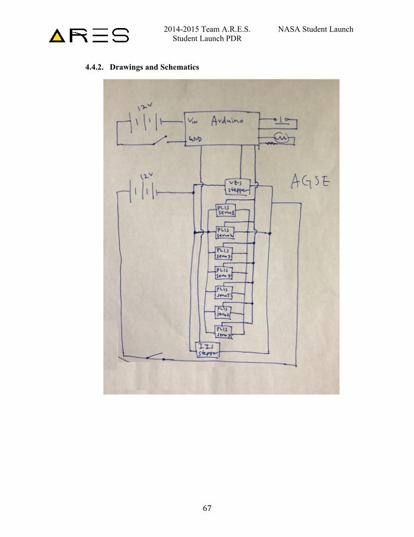
2014-2015 Team A.R.E.S. NASA Student Launch Student Launch PDR
67
4.4.2. Drawings and Schematics
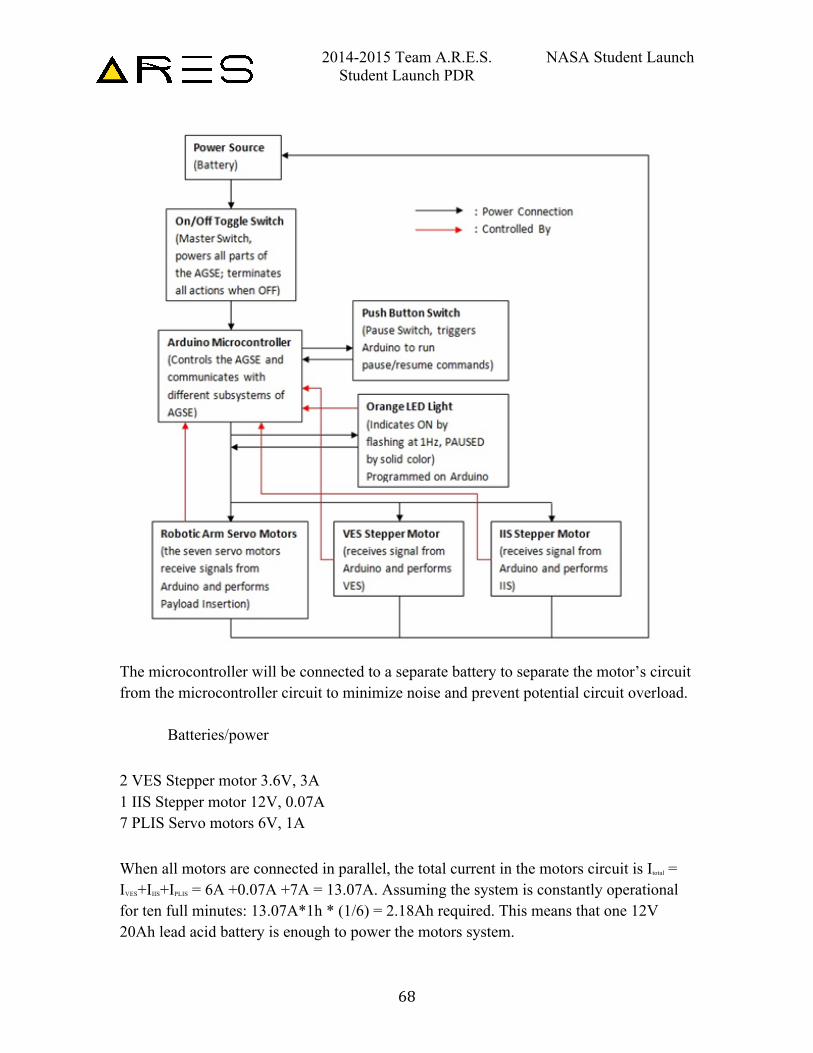
2014-2015 Team A.R.E.S. NASA Student Launch Student Launch PDR
68
The microcontroller will be connected to a separate battery to separate the motor’s circuit from the microcontroller circuit to minimize noise and prevent potential circuit overload. Batteries/power 2 VES Stepper motor 3.6V, 3A 1 IIS Stepper motor 12V, 0.07A 7 PLIS Servo motors 6V, 1A When all motors are connected in parallel, the total current in the motors circuit is Itotal = IVES+IIIS+IPLIS = 6A +0.07A +7A = 13.07A. Assuming the system is constantly operational for ten full minutes: 13.07A*1h * (1/6) = 2.18Ah required. This means that one 12V 20Ah lead acid battery is enough to power the motors system.
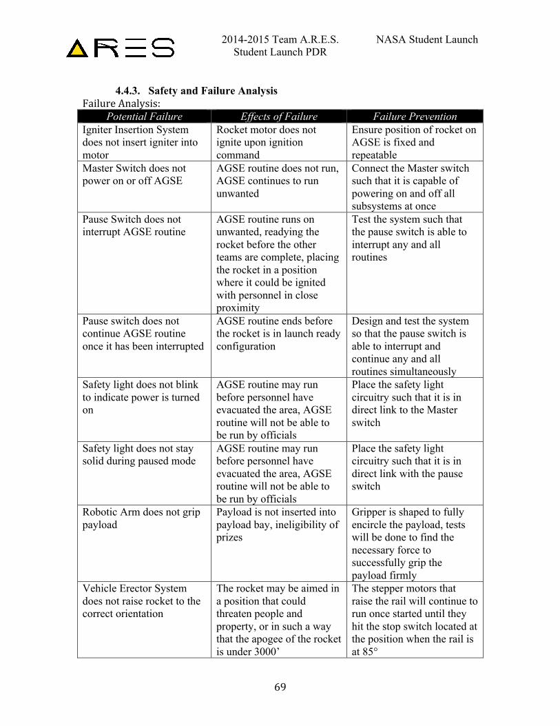
2014-2015 Team A.R.E.S. NASA Student Launch Student Launch PDR
69
4.4.3. Safety and Failure Analysis Failure Analysis:
Potential Failure Effects of Failure Failure Prevention Igniter Insertion System does not insert igniter into motor
Rocket motor does not ignite upon ignition command
Ensure position of rocket on AGSE is fixed and repeatable
Master Switch does not power on or off AGSE
AGSE routine does not run, AGSE continues to run unwanted
Connect the Master switch such that it is capable of powering on and off all subsystems at once
Pause Switch does not interrupt AGSE routine
AGSE routine runs on unwanted, readying the rocket before the other teams are complete, placing the rocket in a position where it could be ignited with personnel in close proximity
Test the system such that the pause switch is able to interrupt any and all routines
Pause switch does not continue AGSE routine once it has been interrupted
AGSE routine ends before the rocket is in launch ready configuration
Design and test the system so that the pause switch is able to interrupt and continue any and all routines simultaneously
Safety light does not blink to indicate power is turned on
AGSE routine may run before personnel have evacuated the area, AGSE routine will not be able to be run by officials
Place the safety light circuitry such that it is in direct link to the Master switch
Safety light does not stay solid during paused mode
AGSE routine may run before personnel have evacuated the area, AGSE routine will not be able to be run by officials
Place the safety light circuitry such that it is in direct link with the pause switch
Robotic Arm does not grip payload
Payload is not inserted into payload bay, ineligibility of prizes
Gripper is shaped to fully encircle the payload, tests will be done to find the necessary force to successfully grip the payload firmly
Vehicle Erector System does not raise rocket to the correct orientation
The rocket may be aimed in a position that could threaten people and property, or in such a way that the apogee of the rocket is under 3000’
The stepper motors that raise the rail will continue to run once started until they hit the stop switch located at the position when the rail is at 85°
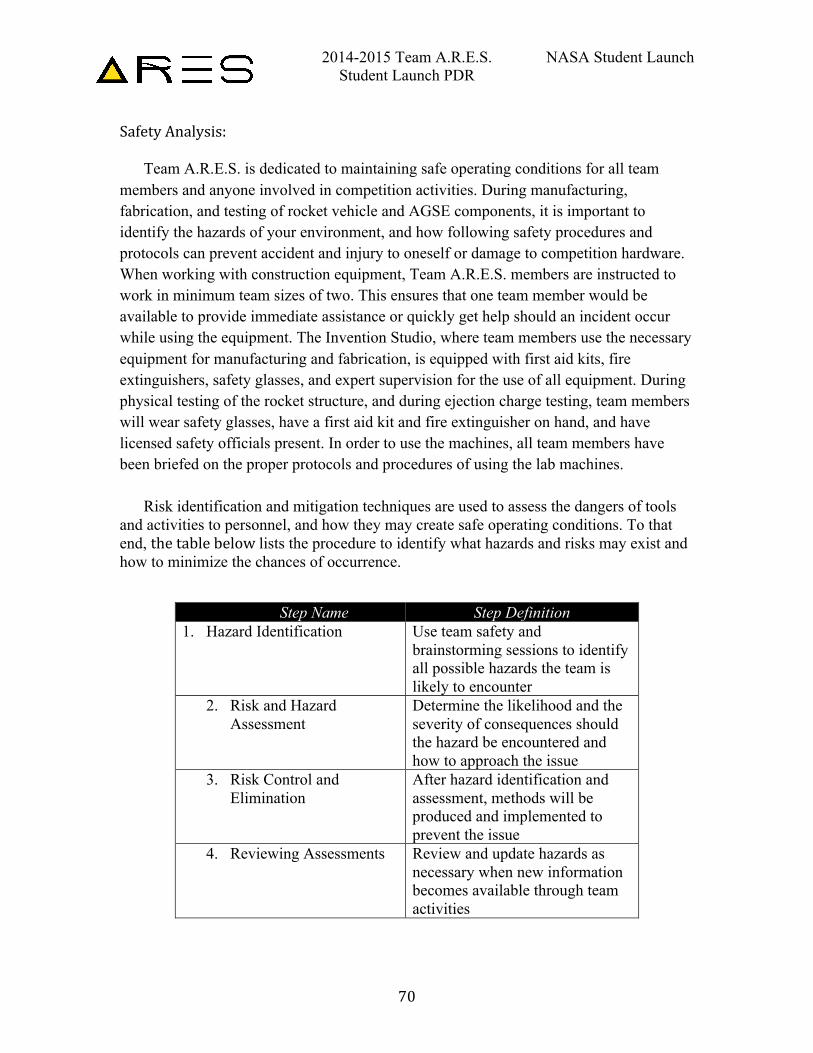
2014-2015 Team A.R.E.S. NASA Student Launch Student Launch PDR
70
Safety Analysis:
Team A.R.E.S. is dedicated to maintaining safe operating conditions for all team members and anyone involved in competition activities. During manufacturing, fabrication, and testing of rocket vehicle and AGSE components, it is important to identify the hazards of your environment, and how following safety procedures and protocols can prevent accident and injury to oneself or damage to competition hardware. When working with construction equipment, Team A.R.E.S. members are instructed to work in minimum team sizes of two. This ensures that one team member would be available to provide immediate assistance or quickly get help should an incident occur while using the equipment. The Invention Studio, where team members use the necessary equipment for manufacturing and fabrication, is equipped with first aid kits, fire extinguishers, safety glasses, and expert supervision for the use of all equipment. During physical testing of the rocket structure, and during ejection charge testing, team members will wear safety glasses, have a first aid kit and fire extinguisher on hand, and have licensed safety officials present. In order to use the machines, all team members have been briefed on the proper protocols and procedures of using the lab machines.
Risk identification and mitigation techniques are used to assess the dangers of tools
and activities to personnel, and how they may create safe operating conditions. To that end, the table below lists the procedure to identify what hazards and risks may exist and how to minimize the chances of occurrence.
Step Name Step Definition 1. Hazard Identification Use team safety and
brainstorming sessions to identify all possible hazards the team is likely to encounter
2. Risk and Hazard Assessment
Determine the likelihood and the severity of consequences should the hazard be encountered and how to approach the issue
3. Risk Control and Elimination
After hazard identification and assessment, methods will be produced and implemented to prevent the issue
4. Reviewing Assessments Review and update hazards as necessary when new information becomes available through team activities
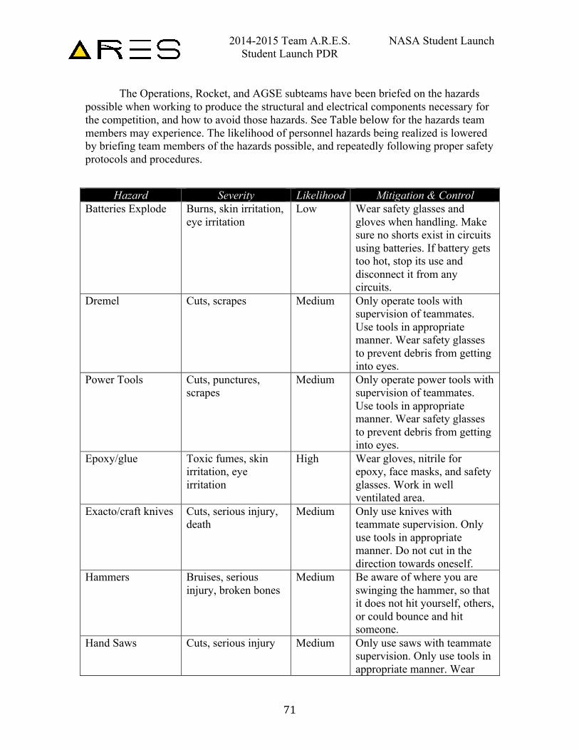
2014-2015 Team A.R.E.S. NASA Student Launch Student Launch PDR
71
The Operations, Rocket, and AGSE subteams have been briefed on the hazards possible when working to produce the structural and electrical components necessary for the competition, and how to avoid those hazards. See Table below for the hazards team members may experience. The likelihood of personnel hazards being realized is lowered by briefing team members of the hazards possible, and repeatedly following proper safety protocols and procedures.
Hazard Severity Likelihood Mitigation & Control Batteries Explode Burns, skin irritation,
eye irritation Low Wear safety glasses and
gloves when handling. Make sure no shorts exist in circuits using batteries. If battery gets too hot, stop its use and disconnect it from any circuits.
Dremel Cuts, scrapes Medium Only operate tools with supervision of teammates. Use tools in appropriate manner. Wear safety glasses to prevent debris from getting into eyes.
Power Tools Cuts, punctures, scrapes
Medium Only operate power tools with supervision of teammates. Use tools in appropriate manner. Wear safety glasses to prevent debris from getting into eyes.
Epoxy/glue Toxic fumes, skin irritation, eye irritation
High Wear gloves, nitrile for epoxy, face masks, and safety glasses. Work in well ventilated area.
Exacto/craft knives Cuts, serious injury, death
Medium Only use knives with teammate supervision. Only use tools in appropriate manner. Do not cut in the direction towards oneself.
Hammers Bruises, serious injury, broken bones
Medium Be aware of where you are swinging the hammer, so that it does not hit yourself, others, or could bounce and hit someone.
Hand Saws Cuts, serious injury Medium Only use saws with teammate supervision. Only use tools in appropriate manner. Wear
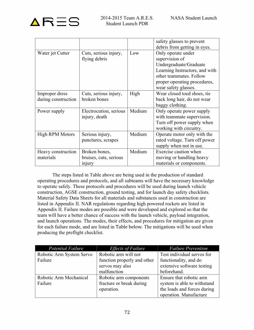
2014-2015 Team A.R.E.S. NASA Student Launch Student Launch PDR
72
safety glasses to prevent debris from getting in eyes.
Water jet Cutter Cuts, serious injury, flying debris
Low Only operate under supervision of Undergraduate/Graduate Learning Instructors, and with other teammates. Follow proper operating procedures, wear safety glasses.
Improper dress during construction
Cuts, serious injury, broken bones
High Wear closed toed shoes, tie back long hair, do not wear baggy clothing.
Power supply Electrocution, serious injury, death
Medium Only operate power supply with teammate supervision. Turn off power supply when working with circuitry.
High RPM Motors Serious injury, punctures, scrapes
Medium Operate motor only with the rated voltage. Turn off power supply when not in use.
Heavy construction materials
Broken bones, bruises, cuts, serious injury
Medium Exercise caution when moving or handling heavy materials or components.
The steps listed in Table above are being used in the production of standard
operating procedures and protocols, and all subteams will have the necessary knowledge to operate safely. These protocols and procedures will be used during launch vehicle construction, AGSE construction, ground testing, and for launch day safety checklists. Material Safety Data Sheets for all materials and substances used in construction are listed in Appendix II. NAR regulations regarding high powered rockets are listed in Appendix II. Failure modes are possible and were developed and explored so that the team will have a better chance of success with the launch vehicle, payload integration, and launch operations. The modes, their effects, and procedures for mitigation are given for each failure mode, and are listed in Table below. The mitigations will be used when producing the preflight checklist.
Potential Failure Effects of Failure Failure Prevention Robotic Arm System Servo Failure
Robotic arm will not function properly and other servos may also malfunction
Test individual servos for functionality, and do extensive software testing beforehand.
Robotic Arm Mechanical Failure
Robotic arm components fracture or break during operation.
Ensure that robotic arm system is able to withstand the loads and forces during operation. Manufacture
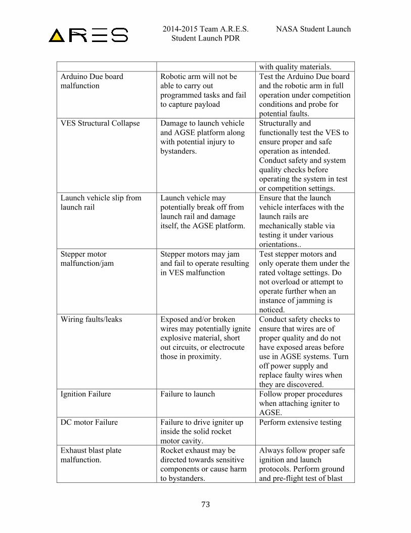
2014-2015 Team A.R.E.S. NASA Student Launch Student Launch PDR
73
with quality materials. Arduino Due board malfunction
Robotic arm will not be able to carry out programmed tasks and fail to capture payload
Test the Arduino Due board and the robotic arm in full operation under competition conditions and probe for potential faults.
VES Structural Collapse Damage to launch vehicle and AGSE platform along with potential injury to bystanders.
Structurally and functionally test the VES to ensure proper and safe operation as intended. Conduct safety and system quality checks before operating the system in test or competition settings.
Launch vehicle slip from launch rail
Launch vehicle may potentially break off from launch rail and damage itself, the AGSE platform.
Ensure that the launch vehicle interfaces with the launch rails are mechanically stable via testing it under various orientations..
Stepper motor malfunction/jam
Stepper motors may jam and fail to operate resulting in VES malfunction
Test stepper motors and only operate them under the rated voltage settings. Do not overload or attempt to operate further when an instance of jamming is noticed.
Wiring faults/leaks Exposed and/or broken wires may potentially ignite explosive material, short out circuits, or electrocute those in proximity.
Conduct safety checks to ensure that wires are of proper quality and do not have exposed areas before use in AGSE systems. Turn off power supply and replace faulty wires when they are discovered.
Ignition Failure Failure to launch Follow proper procedures when attaching igniter to AGSE.
DC motor Failure Failure to drive igniter up inside the solid rocket motor cavity.
Perform extensive testing
Exhaust blast plate malfunction.
Rocket exhaust may be directed towards sensitive components or cause harm to bystanders.
Always follow proper safe ignition and launch protocols. Perform ground and pre-flight test of blast
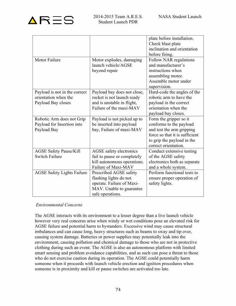
2014-2015 Team A.R.E.S. NASA Student Launch Student Launch PDR
74
plate before installation. Check blast plate inclination and orientation before firing.
Motor Failure Motor explodes, damaging launch vehicle/AGSE beyond repair
Follow NAR regulations and manufacturer’s instructions when assembling motor. Assemble motor under supervision.
Payload is not in the correct orientation when the Payload Bay closes
Payload bay does not close, rocket is not launch ready and is unstable in flight, Failure of the maxi-MAV
Hard-code the angles of the robotic arm to have the payload in the correct orientation when the payload bay closes.
Robotic Arm does not Grip Payload for Insertion into Payload Bay
Payload is not picked up to be inserted into payload bay, Failure of maxi-MAV
Form the gripper so it conforms to the payload and test the arm gripping force so that it is sufficient to grip the payload in the correct orientation.
AGSE Safety Pause/Kill Switch Failure
AGSE safety electronics fail to pause or completely kill autonomous operations. Failure of Maxi-MAV
Conduct extensive testing of the AGSE safety electronics both as separate and a whole system.
AGSE Safety Lights Failure Prescribed AGSE safety flashing lights do not operate. Failure of Maxi-MAV. Unable to guarantee safe operations.
Perform functional tests to ensure proper operation of safety lights.
Environmental Concerns The AGSE interacts with its environment to a lesser degree than a live launch vehicle however very real concerns arise when windy or wet conditions pose an elevated risk for AGSE failure and potential harm to bystanders. Excessive wind may cause structural imbalances and can cause long, heavy structures such as beams to sway and tip over, causing system damage. Batteries or power supplies may potentially leak into the environment, causing pollution and chemical damage to those who are not in protective clothing during such an event. The AGSE is also an autonomous platform with limited smart sensing and problem avoidance capabilities, and as such can pose a threat to those who do not exercise caution during its operation. The AGSE could potentially harm someone when it proceeds with launch vehicle erection and ignition procedures when someone is in proximity and kill or pause switches are activated too late.
2014-2015 Team A.R.E.S. NASA Student Launch Student Launch PDR
75
4.5. AGSE Concept Features and Definition
Georgia Tech’s AGSE stresses practicality and feasibility of successful mission completion, and in the spirit of good engineering, desires to be as cost-effective as possible.
Many avenues for creativity exist in the process of building, testing and refining the current preliminary design, where team members can come up with innovative technical design solutions to optimize and refine AGSE performance. The team acknowledges the value and reliability of heritage or mature technologies and incorporates them extensively in the design of the AGSE.
The challenge of fabricating a high-performance system in the most economical fashion possible reflects “real-world” constraints imposed by budget and time limitations and is an exercise in the efficient use of resources in a variety of technology based R&D projects. The process and end-product of navigating through various constraints presented both from NASA SL mission criteria and limitations in financial & human resources are significant: students learn to work efficiently and creatively while delivering cost-effective solutions that can be scaled up and deployed in more rigorous and challenging NASA missions. In particular this year’s Maxi-MAV (Mars Ascent Vehicle)/Centennial Challenge will have considerable applicability to NASA’s current efforts to explore and study Mars.
The AGSE subteam along with the assistance of other subteams under the Georgia
Tech NASA SL team are equipped with the technical & engineering knowledge and skill in order to complete all steps related to the manufacturing, testing and integration of AGSE subsystems.
4.6. Science Value
The AGSE’s objective and mission success criteria entails it being able to successfully capture and transport a defined payload, load it into a launch vehicle, erect the launch vehicle and ultimately ignite it for launch. The design and construction of the AGSE follows a creative problem solving logic where a team must analyze and break down a complex problem into more simple and well defined subproblems, and in turn come up with feasible solutions for those. Various technologies are considered and eliminated based on feasibility, efficacy and robustness for mission success. There is merit to such exercises as the manufacturing of the AGSE invokes the use of carefully planned experiment and data analysis, especially for electronic signals and their use in systems controls (trying to reduce noise and error in the completion of tasks) as well as
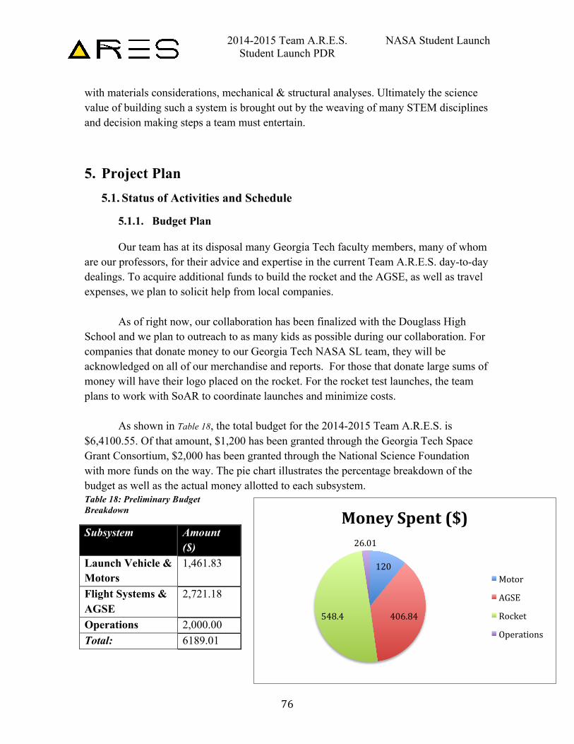
2014-2015 Team A.R.E.S. NASA Student Launch Student Launch PDR
76
with materials considerations, mechanical & structural analyses. Ultimately the science value of building such a system is brought out by the weaving of many STEM disciplines and decision making steps a team must entertain.
5. Project Plan 5.1. Status of Activities and Schedule
5.1.1. Budget Plan
Our team has at its disposal many Georgia Tech faculty members, many of whom are our professors, for their advice and expertise in the current Team A.R.E.S. day-to-day dealings. To acquire additional funds to build the rocket and the AGSE, as well as travel expenses, we plan to solicit help from local companies.
As of right now, our collaboration has been finalized with the Douglass High School and we plan to outreach to as many kids as possible during our collaboration. For companies that donate money to our Georgia Tech NASA SL team, they will be acknowledged on all of our merchandise and reports. For those that donate large sums of money will have their logo placed on the rocket. For the rocket test launches, the team plans to work with SoAR to coordinate launches and minimize costs. As shown in Table 18, the total budget for the 2014-2015 Team A.R.E.S. is $6,4100.55. Of that amount, $1,200 has been granted through the Georgia Tech Space Grant Consortium, $2,000 has been granted through the National Science Foundation with more funds on the way. The pie chart illustrates the percentage breakdown of the budget as well as the actual money allotted to each subsystem. Table 18: Preliminary Budget Breakdown
Subsystem Amount ($)
Launch Vehicle & Motors
1,461.83
Flight Systems & AGSE
2,721.18
Operations 2,000.00 Total: 6189.01
120
406.84 548.4
26.01
Money Spent ($)
Motor
AGSE
Rocket
Operations
2014-2015 Team A.R.E.S. NASA Student Launch Student Launch PDR
77
5.1.2. Funding Plan
In order to achieve the maximum goal of raising $10,000 for the rocket and the AGSE and other supports for 2014-2015 Student Launch competition, Team A.R.E.S. have sought sponsorships through four major channels :
• Georgia Tech Alumni
Companies that team members have interned • Local Companies in Atlanta area • Local High Schools The fund raising actions were started with the connections that can be reached on
campus. Operation sub-team talked to several professors separately and obtained the contact information of Georgia Tech Alumni working in the Aerospace field. At the same time, all Team A.R.E.S. members were working together to provide contact information of past companies. Additionally, we compile a list of local high schools with s=lower than average engineering curriculum and we, as a team, arrive and do lots of outreach events. Simultaneously we’ll partner with the high school to provide whatever is necessary for the completion of our products.
After compiling this information, the Outreach and Budget managers reached out to
potential sponsors via phone calls and email. In order to explain the project further, either in-person meetings or virtual meetings via Skype are scheduled to speak with these potential sponsors. Lastly, the Team has also received a dedicated room at Georgia Tech in which the Team can construct and store their launch vehicle, payload, and other non-explosive components.
2014-2015 Team A.R.E.S. NASA Student Launch Student Launch PDR
78
5.1.3. Timeline
The Simple Complexity project is driven by the design deadlines set forth by the NASA SL Program office. These deadlines are listed in .
Deadline Date Proposal 6 OCT Web Presence Established 31 OCT PDR Documentation 5 NOV PDR Teleconference 7-21 NOV CDR Documentation 16 JAN CDR Teleconference 21-31 JAN FRR Documentation 16 MAR FRR Teleconference 18-27 MAR Competition 7-10 APR PLAR Documentation 29 APR
For a broader overview using a Gantt chart, please visit Appendix I.
5.1.4. Educational Engagement
In addition to competing in Huntsville, the 2014-2015 Georgia Tech Team A.R.E.S. has the objective of reaching out to the community of Atlanta and to educational institutions in disadvantaged areas. Georgia Tech’s Vertically Integrated Program (VIP) particularly encourages this outreach. The VIP Program unites undergraduate education and faculty research in a team-based context, providing the students time and context to learn and practice professional skills and encouraging others in the community to develop these skills. As part of this experience, the USLI team takes on the responsibility to contribute in turn to the community and promote scientific and engineering knowledge to high school students throughout Atlanta, particularly those in inner city areas.
The goal of Georgia Tech’s outreach program is to promote and invigorate interest in the Science, Technology, Engineering, and Mathematics (STEM) fields. Team A.R.E.S. is currently in the process of conducting various outreach programs targeting middle and high school Students and Educators. Team A.R.E.S. currently has an outreach request form on their webpage for Educators to request presentations or hands-on activities for their classroom. The team is in the process of answering visit requests from
2014-2015 Team A.R.E.S. NASA Student Launch Student Launch PDR
79
schools in disadvantaged areas of Atlanta, with the goal of encouraging students there to seek careers in STEM fields.
5.1.5. First Lego League
FIRST Lego League is an engineering competition designed for middle school children, the goal of which is to program an autonomous robot to score points in a “Robot Game”. Annual competitions are held centered on a theme exploring a real-world problem. Team A.R.E.S. plans to be present at the Georgia Tech FIRST Lego League Tournament. The team’s booth at the competition will demonstrate how the skills and ideas utilized in FIRST Lego League translate to real world applications. The team will demonstrate how these skills are used to build a launch vehicle and autonomous ground support equipment.
5.1.6. Georgia Tech NSBE
The Georgia Tech chapter of the National Society of Black Engineers (NSBE) is one of the largest student-governed organizations at Georgia Tech. According to its mission statement, NSBE’s mission is “to increase the number of culturally responsible black engineers who excel academically, succeed professionally and positively impact the community”. Team A.R.E.S. is currently in the process of engaging the chapter, coordinating with them on engineering outreach-related events to further both organizations’ outreach goals, and targeting the organization (among others) in the team’s recruiting efforts for the spring semester.
5.1.7. Frederick Douglass High School
Team A.R.E.S. has successfully partnered with Frederick Douglas High School in northwest Atlanta to demonstrate to students the methods the team uses to design and build a launch vehicle and autonomous ground support equipment. The team will accomplish this while demonstrating hands-on design work and encouraging the students to participate in said work during the visiting session. Following the hands-on session, demonstration of the foundations and theory behind this work will commence. The team will focus on demonstrating that Georgia Tech and engineering is an achievable goal and an attainable career path.
2014-2015 Team A.R.E.S. NASA Student Launch Student Launch PDR
80
6. Conclusion
In conclusion, the Georgia Tech Team A.R.E.S. is well underway in the NASA Student Launch Competition. Team ARES has a bright future and after successful completion of the CDR teleconference, we will be full steam ahead on manufacturing components and the next phase on our schedule, the Flight Readiness Review (FRR).
For the buildup to the FRR, Team ARES will have constructed and tested a working AGSE and Launch vehicle. Additionally, a few more tests on the AGSE and ATS will be performed to be 100% sure we are moving in the right direction, and we have data to back us up.
To summarize the AGSE, there will be 3 main systems for the AGSE; the Payload
Insertion System, the Vertical Erector System, and the Igniter Insertion System. All of the systems have just completed the design phase are well under way for the testing and construction phase. Each subsystem will be put under rigorous testing to ensure that the functionality is not compromised.
Additionally, the rocket is designed to reach and Apogee of 3,100 ft. with a total mass of 16.88 lbs. The rocket will be subject to static testing and rigorous design reviews from now until the FRR.
2014-2015 Team A.R.E.S. NASA Student Launch Student Launch PDR
81
Appendix I: Gantt chart
PAGE INTENTIONALLY LEFT BLANK
2014-2015 Team A.R.E.S. NASA Student Launch Student Launch PDR
82
Appendix II: MSDS sheets
PAGE INTENTIONALLY LEFT BLANK