Embed Size (px)
Citation preview

NCMA Research and Education Foundation Final Report Georgia Tech Page 1
Georgia Institute of Technology
College of Architecture
Extending the Design Potential of Concrete Masonry Software T. Russell Gentry, Andres Cavieres, and Tristan Al-Haddad
email: [email protected]
Final Report to
NCMA Education and Research Foundation
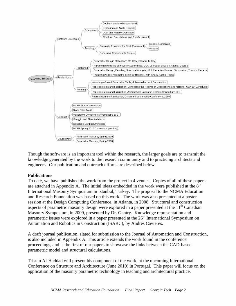
1 December 2009 Project Brief Ground-breaking research in the architectural design and construction community is focusing on new ways of representing buildings and components – both for early design visioning and for construction documentation. The ability to represent complex constructed forms – and take these forms directly into manufacturing is at the heart of parametric modeling and Building Information Modeling (BIM). This project will develop parametric rules for the design of complex forms in concrete masonry – with the goal of being able to represent the curved and corbelled forms necessary to produce non-planar concrete walls and buildings. The object representations will be parametrically coupled with engineering and construction knowledge of masonry so that the resulting geometries are not only interesting, but also build-able using today’s concrete masonry units. The reporting from the BIM models will be of use in both flat and curved walls. The audience for this research is architects who are interested in complex building forms. The goal of the research is to provide computational tools that allow architects to consider concrete masonry as viable means for producing these complex forms. Project Activities during Year One Our work this year has been focused in four major areas: algorithm development and software, publications, outreach, and coursework. The extent of these activities is shown in the figure below. A brief discussion of activities in each of these areas follows. Algorithm Development and Software Implementation The heart of our work is development of algorithms to represent concrete masonry within a CAD environment. In this case, by represent, we mean far more than creating lines and arcs that look like blocks, or even three-dimensional representations of blocks. The representations developed as part of this research are informed by the construction and structural logic that goes along with masonry construction. The representational framework is rich enough so that wall openings, corners, and intersections can be accommodated within the design environment. The CAD representation is tied to automated structural calculations for wall forces and stresses, and subsequent longitudinal reinforcement calculation, embedded in Microsoft Excel. The software environment in which the algorithms are embedded (Bentley Systems, Generative Components) is a parametric modeling environment which itself is embedded within a mainstream CAD system widely used in the architecture-engineering-construction community.
NCMA Research and Education Foundation Final Report Georgia Tech Page 2
Though the software is an important tool within the research, the larger goals are to transmit the knowledge generated by the work to the research community and to practicing architects and engineers. Our publication and outreach efforts are described below. Publications To date, we have published the work from the project in 4 venues. Copies of all of these papers are attached in Appendix A. The initial ideas embedded in the work were published at the 8th International Masonry Symposium in Istanbul, Turkey. The proposal to the NCMA Education and Research Foundation was based on this work. The work was also presented at a poster session at the Design Computing Conference, in Atlanta, in 2008. Structural and construction aspects of parametric masonry design were explored in a paper presented at the 11th Canadian Masonry Symposium, in 2009, presented by Dr. Gentry. Knowledge representation and parametric issues were explored in a paper presented at the 26th International Symposium on Automation and Robotics in Construction (ISARC), by Andres Cavieres. A draft journal publication, slated for submission to the Journal of Automation and Construction, is also included in Appendix A. This article extends the work found in the conference proceedings, and is the first of our papers to showcase the links between the CAD-based parametric model and structural calculations. Tristan Al-Haddad will present his component of the work, at the upcoming International Conference on Structure and Architecture (June 2010) in Portugal. This paper will focus on the application of the masonry parametric technology in teaching and architectural practice.
NCMA Research and Education Foundation Final Report Georgia Tech Page 3
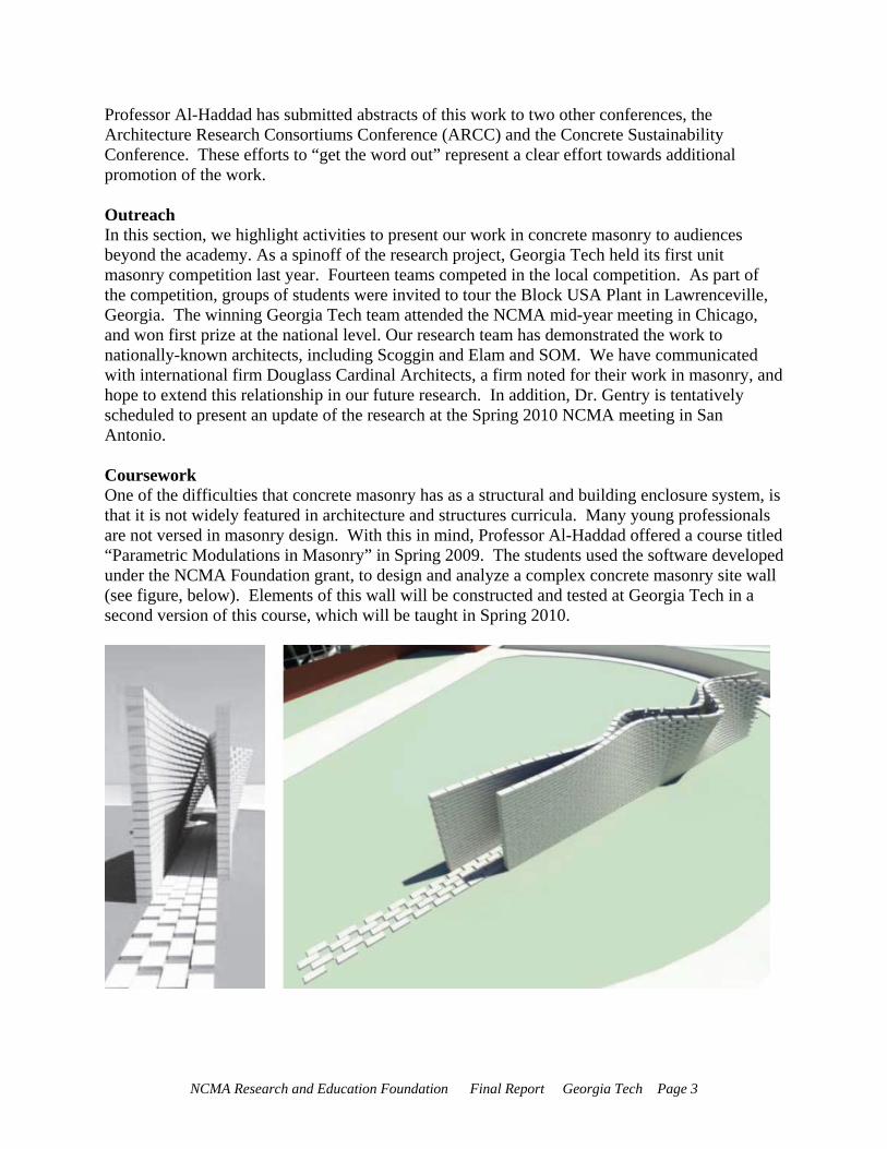
Professor Al-Haddad has submitted abstracts of this work to two other conferences, the Architecture Research Consortiums Conference (ARCC) and the Concrete Sustainability Conference. These efforts to “get the word out” represent a clear effort towards additional promotion of the work. Outreach In this section, we highlight activities to present our work in concrete masonry to audiences beyond the academy. As a spinoff of the research project, Georgia Tech held its first unit masonry competition last year. Fourteen teams competed in the local competition. As part of the competition, groups of students were invited to tour the Block USA Plant in Lawrenceville, Georgia. The winning Georgia Tech team attended the NCMA mid-year meeting in Chicago, and won first prize at the national level. Our research team has demonstrated the work to nationally-known architects, including Scoggin and Elam and SOM. We have communicated with international firm Douglass Cardinal Architects, a firm noted for their work in masonry, and hope to extend this relationship in our future research. In addition, Dr. Gentry is tentatively scheduled to present an update of the research at the Spring 2010 NCMA meeting in San Antonio. Coursework One of the difficulties that concrete masonry has as a structural and building enclosure system, is that it is not widely featured in architecture and structures curricula. Many young professionals are not versed in masonry design. With this in mind, Professor Al-Haddad offered a course titled “Parametric Modulations in Masonry” in Spring 2009. The students used the software developed under the NCMA Foundation grant, to design and analyze a complex concrete masonry site wall (see figure, below). Elements of this wall will be constructed and tested at Georgia Tech in a second version of this course, which will be taught in Spring 2010.
NCMA Research and Education Foundation Final Report Georgia Tech Page 4
Summary of Outreach Strategy + Future Plans This research, enabled by the NCMA Research and Education Foundation, is ongoing. The development of parametric relationships for masonry design will form the basis for Andres Cavieres’ doctoral dissertation, to be completed in 2011. We are continuing to publish the work in academic venues, with one accepted and two pending conference presentations. In Spring 2010, Professor Al-Haddad (along with Dr. Gentry and Andres Cavieres) will offer the second concrete masonry workshop to graduate and undergraduate students at Georgia Tech. We anticipate presenting the work at the NCMA Spring meeting in San Antonio. Conclusion We believe that the capabilities of concrete masonry go beyond the traditional flat, load-bearing wall in industrial and institutional buildings. Our work seeks to expand architects’ concepts for masonry through the development of new computational tools and the application of these tools in our teaching and outreach. Regardless of our interest in complex geometry, the research results will have an important impact on conventional masonry systems as well. We are looking for additional funding opportunities to continue our work in concrete masonry, and will be applying for a second year of funding from NCMA at the appropriate time.
NCMA Research and Education Foundation Final Report Georgia Tech Page 5
Appendix A
Publications
1. Andres Cavieres, Russell Gentry, and Tristan Al-Haddad, (2008), “Parametric Design Of Masonry Buildings. Embedding Construction Knowledge,” Proceedings of the 2008 8th International Seminar on Structural Masonry (ISSM), Istanbul, Turkey – November 5-7, 2008.
2. Andres Cavieres and Russell Gentry, (2008), “Parametric Modeling of Masonry
Assemblies”, Poster Session, Third International Conference On Design Computing And Cognition, Atlanta, Georgia, 21-25 June, 2008.
3. T. Russell Gentry, Andres Cavieres, and Tristan Al-Haddad (2009), “Parametric Design,
Detailing and Structural Analysis Of Doubly-Curved Load-Bearing Block Walls”, 11th Canadian Masonry Symposium, Toronto, Ontario, May 31- June 3, 2009.
4. Andres Cavieres, Russell Gentry, and Tristan Al-Haddad, (2009), “Rich Knowledge
Parametric Tools for Concrete Masonry Design: Automation of Preliminary Structural Analysis, Detailing and Specifications”, Proceedings of the 2009 26th International Symposium on Automation and Robotics in Construction (ISARC), Austin, Texas, U.S. - June 24-27, 2009.
5. Andres Cavieres, Russell Gentry, and Tristan Al-Haddad, (pending), “Knowledge-Based
Parametric Tools for Concrete Masonry Walls: Conceptual Design and Preliminary Structural Analysis”, prepared for Journal of Automation and Construction.
[Please do not distribute the pending journal article outside of NCMA as this article will be undergoing the peer review process and may require revision. Once published this article will be the property of the journal in which it appears] For a copy of the Journal of Automation and Construction article, contact:Professor T. Russell Gentry, Ph.D., PE Associate Professor, Architecture Program College of Architecture
Georgia Institute of Technology Atlanta, GA 30332-0155
Preprint:
PARAMETRIC DESIGN OF MASONRY BUILDINGS. EMBEDDING CONSTRUCTION KNOWLEDGE
Andres Cavieres1 , Russell Gentry2
and Tristan Al-Haddad3
published in:
Proceedings of the 2008 8th International Seminar on Structural Masonry (ISSM), Istanbul, Turkey – November 5-7, 2008.
1 Georgia Institute of Technology, College of Architecture, Atlanta, Georgia, United States, [email protected] Georgia Institute of Technology, College of Architecture, Atlanta, Georgia, United States, [email protected] Institute of Technology, College of Architecture, Atlanta, Georgia, United States, [email protected]
PARAMETRIC DESIGN OF MASONRY BUILDINGS EMBEDDING CONSTRUCTION KNOWLEDGE INTO
DESIGN MODELS
Andres CAVIERES1, Russell GENTRY2 and Tristan AL-HADDAD3
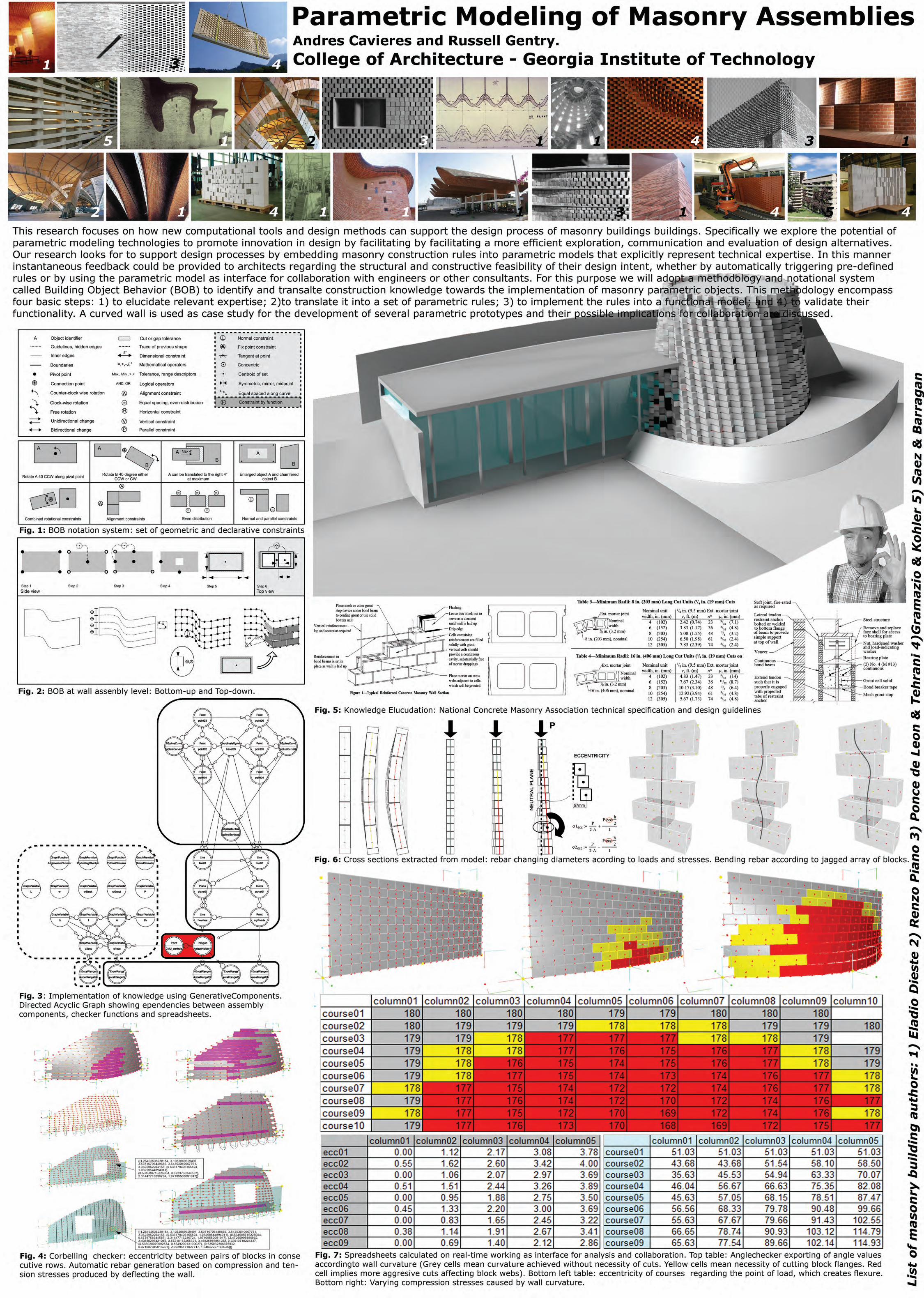
ABSTRACT This paper focuses on how new computational tools and design methods can support the design process of masonry buildings. Specifically we discuss the potential of parametric modeling technologies to promote innovation in the design by facilitating a more efficient exploration, communication and evaluation of design alternatives. Our research focuses on supporting design processes by embedding masonry construction rules into parametric models that explicitly represent technical expertise. In this manner instantaneous feedback could be provided to architects regarding the structural and constructive feasibility of their design intent, whether by automatically triggering pre-defined rules or by using the parametric model as interface for collaboration with engineers. For this purpose we will adopt a methodology and notation called Building Object Behavior (BOB) to identify and translate construction knowledge towards the implementation of masonry parametric objects. This methodology encompasses fours basic steps: 1) to elucidate relevant expertise; 2) to translate it into a set of parametric rules; 3) to implement the rules into a functional model; and 4) to validate their functionality. A curved masonry wall is used as case study for the development of several parametric prototypes and their possible implications for collaboration are discussed. KEYWORDS BIM, Parametric modeling, Design Process, Construction Knowledge, Masonry Assembly 1 INTRODUCTION Despite the fact that the masonry industry and academia have continuously moved forward important advances on new masonry unit types, structural analysis methods and more efficient construction processes [1], [2] there is still a perception that the limits of masonry are not being challenged by the architects. Current technical innovations are not being extensively transferred into architectural design practice and in most cases new masonry buildings continue to adopt conventional and rather conservative solutions. A number of misconceptions and prejudices among architects, such as the high cost of masonry construction and its limited formal possibilities are threatening the competitiveness of this material in relation with other systems. One main cause for such misconceptions is the lack of knowledge, especially among young architects about different masonry types and their architectural possibilities. It can be argued that challenging masonry limits requires a considerable level of expertise, which is in contradiction with the lack of knowledge. Furthermore, expertise on masonry design is, as in any other type of domain, rare and expensive. Construction of complex or unusual configurations is naturally considered risky and complicated without expert knowledge and judgment. To avoid this problem the natural path becomes the adoption of conventional solutions or simple variations of a well known theme that do not cause serious structural or spatial consequences. In this manner possible difficulties are kept under control by adopting prescribed detail specifications and standard formulas. A second reason besides the above mentioned lack of technical knowledge is the reduced number of tools currently available for designers to represent and explore new masonry configurations in a more efficient way. In the absence of such tools what becomes costly is the
1 Georgia Institute of Technology, College of Architecture, Atlanta, Georgia, United States, [email protected] Georgia Institute of Technology, College of Architecture, Atlanta, Georgia, United States, [email protected] Georgia Institute of Technology, College of Architecture, Atlanta, Georgia, United States, [email protected]
amount of effort architects have to put on modeling and detailing a building with hundreds or probably thousands of masonry units. New Building Information Modeling technologies have been developed in recent years to handle similar complexities inherent to architectural design. They are already being used within the AEC industry for advanced design exploration, sophisticated engineering analysis and precise specification of building assemblies for fabrication. The parametric modeling capabilities of these technologies have facilitated the incorporation of technical knowledge about material's behavior, fabrication and constructive processes on early design stages, increasing architect's understanding of design implications and promoting successful innovations [3]. This paper looks to address this issue focusing on the development of similar capabilities to promote the adoption of concrete masonry systems in contemporary design practice. For that purpose we explore some methodologies to incorporate masonry construction knowledge into the design process by using state-of-art computational technologies. The final goal is to improve the design and construction processes by supporting the creation, testing and evaluation of a higher number of design alternatives from the beginning. In this scenario an important emphasis will be put on formal variability and geometric complexity of building envelopes. Masonry units allow a wide and rich scope of configurations, and several types of formal results, whether in load-bearing mode or as cladding. This feature can be intensively explored by means of parametric modeling, making the representation of complex geometries and assemblies an easier and more realistic approach towards innovation in the design of masonry buildings. 1.1 The limitations of Conventional CAD Systems Masonry construction involves the placement and bonding of individual modular units into a continuum. The geometric characteristics of this continuum as well as the specific patterns adopted for the placement of units are part of a sequence of decisions made by architects and engineers when looking to solve a number of simultaneous issues. Structural stability, functionality, aesthetics and satisfactory performance are some of the fundamental requirements that any building must satisfy as part of an integrative design. To provide a balanced solution is not an easy task and whenever the equation seems to be accomplished the chances of exploring other valid alternatives are going to be drastically reduced. A better solution often emerges throughout exhaustive comparison among different models from a wider pool of alternatives. However designers usually succumb to the temptation of believing that the first options are good enough or they simply stick to what they already know well, avoiding in this way further explorations. This phenomenon of accepting the “already-known” or the quickest solution has been called “design fixation” [4], [5]. and it can be argued that the tendency to follow it becomes particularly strong when the number of parts involved in a problem is high. A continuum assembled by several small units, i.e., a masonry wall, a cladding system, a tiled roof or a brick pavement arise as typical examples where the number of parts implies such amount of interdependencies that any further exploration beyond what is commonly accepted is considered an unnecessary extra-effort. The fixation on conventional configurations is generally accepted as “default” and in some cases it is even justified under claimings of adherence to traditional constructive wisdom. This over-simplification is evident on conventions adopted for representation of masonry elements in CAD systems. The complexity of a masonry wall is reduced by denoting it as an homogeneous volume, i.e., a rectangular block that do not describe the geometry of its units nor their bonding system. Only when the model is rendered for visualization purposes then a picture (a raster image of a masonry surface) is mapped onto the model in order to express its material appearance. In terms of quantification of units a simple calculation is made as function of the total area to be covered, the size of the chosen unit and the type of mortar required. CAD systems facilitate this task by being able to calculate this simple formula automatically. However they don't geometrically represent all the components nor consider cases such as block cuts or custom units that could be required for some special situations. If a designer would intend to explore different types of building forms, unusual bonding patterns or special details, a complete representation of the masonry assembly would be the most appropriate way to get better insights. In a conventional CAD system this requirement would mean the necessity of modeling all the units one by one (actually just once but copying it several times), place them on their respective positions and set all the joints, angles and encounters “by hand”. Once the assembly is modeled any modification on design implies an excessively difficult, time consuming and error prone manual process.
2 KNOWLEDGE-RICH PARAMETRIC SYSTEMS IN THE AEC INDUSTRY There are currently important software developments going on to solve this issue by taking advantage of computing power to automate repetitive tasks. In this context such developments strongly suggest that traditional CAD methods of representing assemblies by oversimplifying their geometry are going to be replaced by another one where all relevant parts have to be explicitly modeled. The potentials benefits of such type of representation lie on the intelligent behavior that parametric components can exhibit. Parametric modeling provide mechanisms to translate and embed both domain expertise and design intent into the internal structure of building objects in such a manner that they behave and adapt automatically according to design changes [6]. The implementation of domain expertise (or knowledge) and design intent operates through geometric rules and algebraic expressions that control the position, shape and attributes of parametric objects. The ability to automatically access and manipulate geometric dependent data, making it interoperable and reusable is the key feature of parametric systems that allows the generation of rich building information [7]. A fully detailed 3D model becomes then the base representation for building projects, working as a central data source for architects, engineers and contractors during the entire life cycle of the project. Some of the potential benefits of such computer-integrated construction work flow are: Reduced design and drafting costs; automation in fabrication; reduced error rates in construction and enhanced ability to consider alternative solutions [8]. Several construction industries have recognized this potential to improve their businesses. They have taken the lead in developing their own parametric systems to support their design and fabrication processes by embedding technical expertise directly into domain-specific modelers. BIM parametric systems such as Xsteel, SDS/2, 3D+ and StruCad are some examples of successful development of highly specialized tools that have supported the design, fabrication, construction and erection of steel structures for more than a decade. Following the example of the structural steel industry, the North-American precast concrete industry started a research and development (R&D) initiative some years ago to satisfy their process requirements. For this purpose a consortium formed by 23 companies from United States, Mexico and Canada worked with a group of researchers from the GeorgiaTech and the Technion Institute of Israel, ending-up with the development of a precast parametric modeling system based on Tekla Structures. (For more details on the development of the precast concrete project see Eastman [6]). According to Eastman one of the major challenges in the development of such rich-knowledge parametric systems is to find a general method to facilitate the translation of relevant expertise into a set of functional parametric objects. To solve this issue the Building Object Behavior (BOB) description method and notation was developed by his team to assist in this task [7]. Nevertheless BOB was developed not only focusing on the precast concrete industry, but rather though to be useful on other types of design problems and construction systems. In this manner the general and abstract nature of BOB methodology and notation allowed us to use it as basic reference for the to the definition of parametric behavior of masonry models. In the next section we introduce the main concepts of BOB and elaborate on the ways it can be applied to the development of masonry representations. 3 BUILDING OBJECT BEHAVIOR (BOB) NOTATION AND METHODOLOGY Object behavior in a parametric modeling environment is seen as the ability of a building component or assembly to respond to an internal or external stimulus preserving the original design intent. This response occurs when the system is capable of taking automatic actions in order to “maintain the topological and geometrical consistency of the relationships within and between model objects”. In this manner objects have to be modeled not only as they look but most importantly, as semantic relationships within a specific domain [8]. However a major issue for the implementation of domain specific BIM parametric solutions relates with the problem of how to specify and embed relevant design and engineering knowledge in a parametric modeling system. One of the main difficulties arise from the fact that much of this knowledge is tacit and very hard to be explicitly represented. The tacit nature of design knowledge usually produces different interpretations at the implementation level that may cause several implications downstream such as highly complex and ambiguous models. The fact that a same object behavior can be implemented in different ways raises the question about efficiency, re-usability and scalability of the solution. Therefore there was an urgent need for a a method that could help to rapidly and abstractly capture and represent such behaviors prior any software implementation or modeling activity. This method should help to pre-tune and guide parametric object definition in a testing phase, in such a
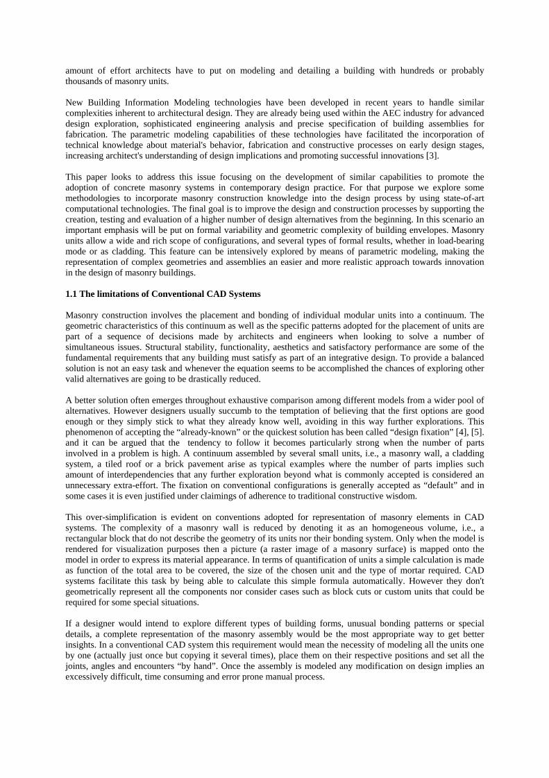
manner that ambiguity and unnecessary complexity could be reduced. According to Lee [7] this approach was also found to be especially appropriate for relatively large and complex parametric modeling activities where effective collaboration is a critical issue. 3.1 BOB Specification The building object behavior (BOB) notation was developed to help designers to define a set of parameters and the relationships that represents the main aspects of a building object and its expected behavior within a given domain. Many of these aspects are geometric in nature or can be expressed in terms of geometric relationships [9]. According to Lee it is essentially graphical shorthand for sharing the descriptions among different members of a collaborative setting. In this notation each shape can be labeled as a real-world object with a unique identifier (e.g., room A, wall W1, a column and so on). The graphical conventions adopted by the notation are the same of engineering drawing; however the drawings do not intend to be an accurate representation of shapes. Only the topological structures are important since the goal is to capture and clearly communicate relevant relationships existing within or between objects. All the accuracy will be parametrically determined by design afterwards. The BOB notation considers four primitive types of object behavior: FIX, ROTATE, TRANSLATE and RESHAPE. Most of object transformations follow one of these primitive types or can be defined as combination of them. Pivot and connection points represent an axis of rotation both in 2D and 3D (Fig. 1). There are also two types of arrows to represent relative movement of objects: rotational movement and directional movement. Both can have associated declarative geometric constraints (called constraint descriptors) to specify in more detail the kind and degree of an expected change, such as tolerance and range descriptors.
Figure 1 Set of primitive constraint types and extended set declarative geometric constraints. White rectangle set extracted from Lee (Lee et. al. 2006). Clear grey extracted or based on Bettig [10]. Dark grey included as an
algorithmic combination of constraints. An extended set of constraint descriptors such as alignment, equal spacing, horizontal, normal constraint, etc. represent spatial relationships regarding other objects or coordinate systems. Most of these descriptors correspond to a selection extracted originally from a taxonomy elaborated by Bettig and Shah [10]. We extended the basic definition of constraints and constraint descriptors used in BOB by including some extra components from Bettig, such as ‘tangent’, 'symmetric / mirror / midpoint', 'concentric' and 'distance along a curve' constraints. A variation of the 'distance along curve' is made by specifying an 'equal spacing along curve' constraint. Additionally a 'centroid of set' is defined as a useful variation of the 'symmetric / mirror / midpoint' constraint. Finally a 'constraint by function' was included denoting complex relationships that have to be managed by algebraic and logical statements that combine different primitive types and constraint descriptors under an algorithmic structure.
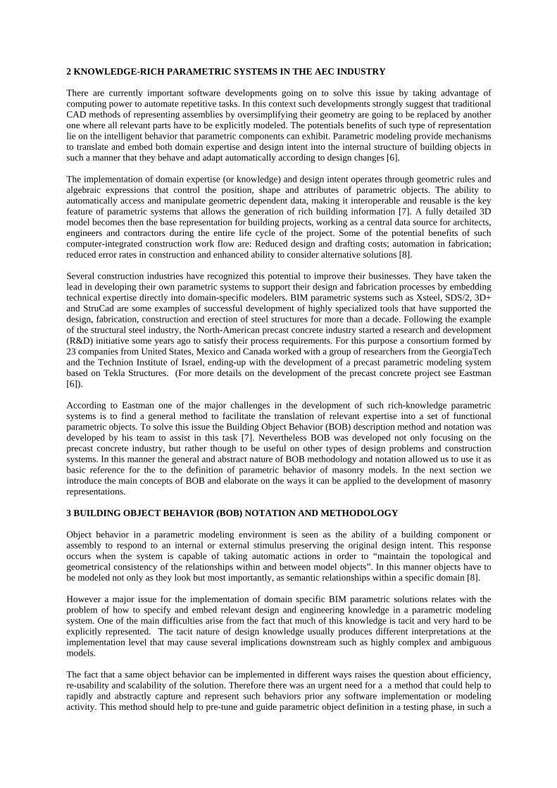
Figure 2 Examples of parametric behaviors declared using BOB notation as defined by Lee el. al. [7]. Most of
them were used in the definition of masonry assembly walls. 4 PARAMETRIC MODELS OF CONCRETE MASONRY ASSEMBLIES USING B.O.B. In this research the implementation of knowledge of masonry design was done through the development of parametric prototypes using an existing parametric CAD system. Curved walls were adopted as case study to be defined parametrically using BOB, in such a way that solutions can be easily extended towards more conventional flat orthogonal walls. So far this process has followed three out of four base steps considered by BOB: 1) Elucidation, 2) Translation and 3) Implementation. The fourth point, validation is pending until a more extensive set of implement models are produced.
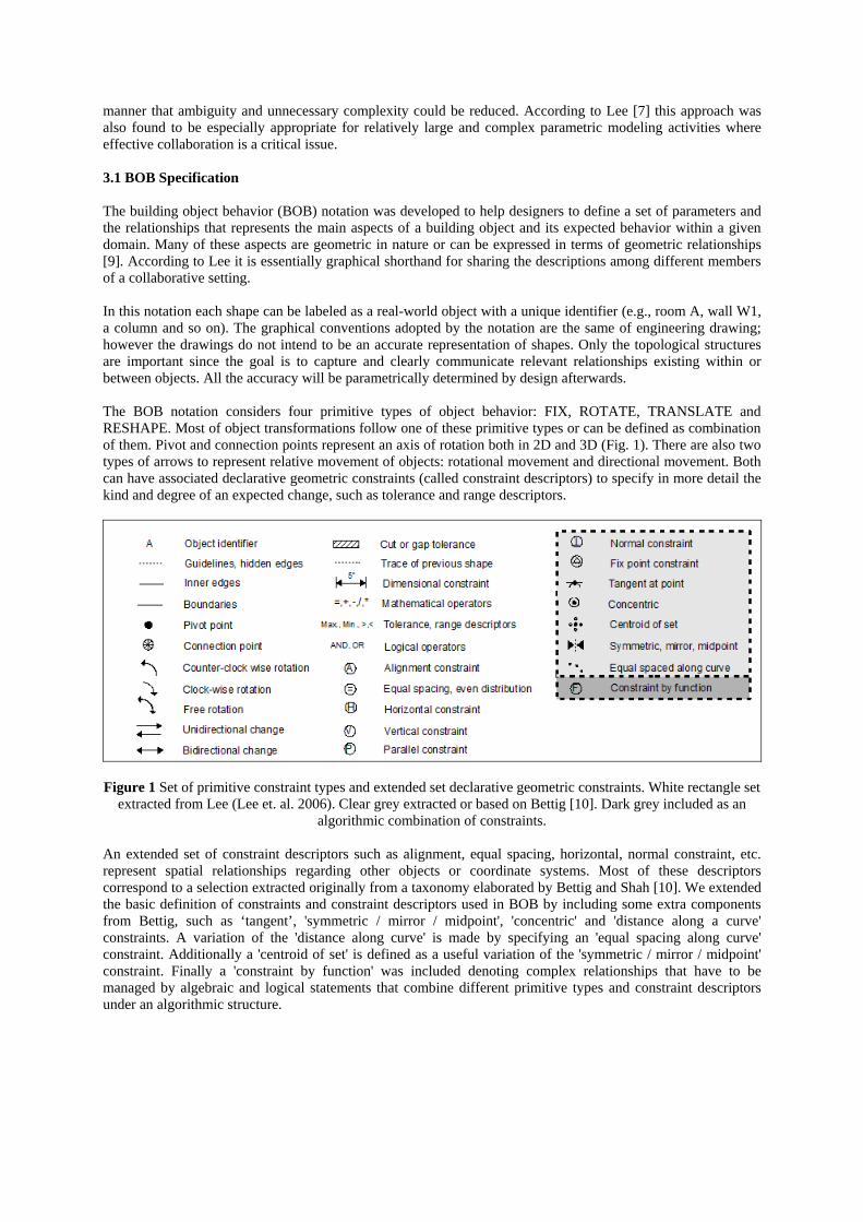
Figure 3 Example of design rule for curved (radial) masonry wall as function of wall radius. Threshold for adoption of standard CMU blocks without cuts, flanged units with removed flanges or cut blocks beyond flanges
compromising block ears. Source: NCMA TEK 5-10A Details (2006) 4.1 Elucidation A curved masonry wall was chosen as case study for the definition of parametric behavior using BOB. The election of a curved geometry allowed the implementation of general solutions that can be easily adapted towards more common flat orthogonal walls. The first step describes the expected behavior of both a single concrete block and an entire wall assembly according to masonry construction guidelines [11], [12], [13], [12]. For this purpose we followed the technical specifications and design recommendations in a series of technical detailing documents provided by the National Concrete Masonry Association of United States [14]. The elucidation process starts by identifying the most relevant relationships exiting is given design problem. Such relationships need not to be explicitly geometric but at least have to provide the basis for a geometric interpretation. Therefore the potential link between design knowledge and a parametric representation of it lies on the clear identification of the building components that can change and how they must do so.
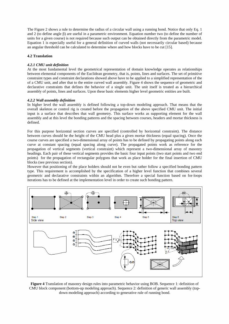
The Figure 2 shows a rule to determine the radius of a circular wall using a running bond. Notice that only Eq. 1 and 2 (to define angle β) are useful in a parametric environment. Equation number two (to define the number of units for a given course) is not required because such output can be obtained directly from the parametric model. Equation 1 is especially useful for a general definition of curved walls (not necessarily circular based) because an angular threshold can be calculated to determine where and how blocks have to be cut [15]. 4.2 Translation 4.2.1 CMU unit definition At the most fundamental level the geometrical representation of domain knowledge operates as relationships between elemental components of the Euclidean geometry, that is, points, lines and surfaces. The set of primitive constraint types and constraint declarations showed above have to be applied to a simplified representation of the of a CMU unit, and after that to the entire curved wall assembly. Figure 4 shows the sequence of geometric and declarative constraints that defines the behavior of a single unit. The unit itself is treated as a hierarchical assembly of points, lines and surfaces. Upon these basic elements higher level geometric entities are built. 4.2.2 Wall assembly definition In higher level the wall assembly is defined following a top-down modeling approach. That means that the overall skeleton or control rig is created before the propagation of the above specified CMU unit. The initial input is a surface that describes that wall geometry. This surface works as supporting element for the wall assembly and at this level the bonding patterns and the spacing between courses, headers and mortar thickness is defined. For this purpose horizontal section curves are specified (controlled by horizontal constraint). The distance between curves should be the height of the CMU head plus a given mortar thickness (equal spacing). Once the course curves are specified a two-dimensional array of points has to be defined by propagating points along each curve at constant spacing (equal spacing along curve). The propagated points work as reference for the propagation of vertical segments (vertical constraint) which represent a two-dimensional array of masonry headings. Each pair of these vertical segments provides the basic four input points (two start points and two end points) for the propagation of rectangular polygons that work as place holder for the final insertion of CMU blocks (see previous section). However that positioning of the place holders should not be even but rather follow a specified bonding pattern type. This requirement is accomplished by the specification of a higher level function that combines several geometric and declarative constraints within an algorithm. Therefore a special function based on for-loops iterations has to be defined at the implementation level in order to create such bonding pattern.
Figure 4 Translation of masonry design rules into parametric behavior using BOB. Sequence 1: definition of CMU block component (bottom-up modeling approach). Sequence 2: definition of generic wall assembly (top-
down modeling approach) according to generative rule of running bond.
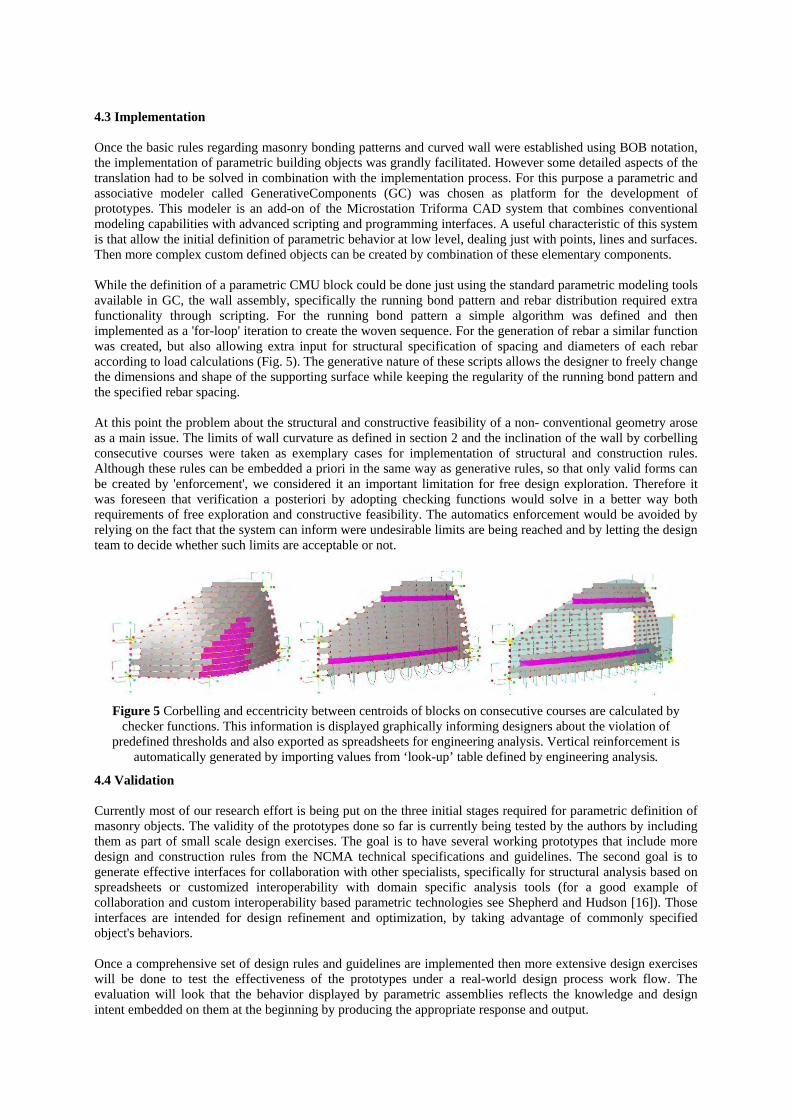
4.3 Implementation Once the basic rules regarding masonry bonding patterns and curved wall were established using BOB notation, the implementation of parametric building objects was grandly facilitated. However some detailed aspects of the translation had to be solved in combination with the implementation process. For this purpose a parametric and associative modeler called GenerativeComponents (GC) was chosen as platform for the development of prototypes. This modeler is an add-on of the Microstation Triforma CAD system that combines conventional modeling capabilities with advanced scripting and programming interfaces. A useful characteristic of this system is that allow the initial definition of parametric behavior at low level, dealing just with points, lines and surfaces. Then more complex custom defined objects can be created by combination of these elementary components. While the definition of a parametric CMU block could be done just using the standard parametric modeling tools available in GC, the wall assembly, specifically the running bond pattern and rebar distribution required extra functionality through scripting. For the running bond pattern a simple algorithm was defined and then implemented as a 'for-loop' iteration to create the woven sequence. For the generation of rebar a similar function was created, but also allowing extra input for structural specification of spacing and diameters of each rebar according to load calculations (Fig. 5). The generative nature of these scripts allows the designer to freely change the dimensions and shape of the supporting surface while keeping the regularity of the running bond pattern and the specified rebar spacing. At this point the problem about the structural and constructive feasibility of a non- conventional geometry arose as a main issue. The limits of wall curvature as defined in section 2 and the inclination of the wall by corbelling consecutive courses were taken as exemplary cases for implementation of structural and construction rules. Although these rules can be embedded a priori in the same way as generative rules, so that only valid forms can be created by 'enforcement', we considered it an important limitation for free design exploration. Therefore it was foreseen that verification a posteriori by adopting checking functions would solve in a better way both requirements of free exploration and constructive feasibility. The automatics enforcement would be avoided by relying on the fact that the system can inform were undesirable limits are being reached and by letting the design team to decide whether such limits are acceptable or not.
Figure 5 Corbelling and eccentricity between centroids of blocks on consecutive courses are calculated by
checker functions. This information is displayed graphically informing designers about the violation of predefined thresholds and also exported as spreadsheets for engineering analysis. Vertical reinforcement is
automatically generated by importing values from ‘look-up’ table defined by engineering analysis.
4.4 Validation Currently most of our research effort is being put on the three initial stages required for parametric definition of masonry objects. The validity of the prototypes done so far is currently being tested by the authors by including them as part of small scale design exercises. The goal is to have several working prototypes that include more design and construction rules from the NCMA technical specifications and guidelines. The second goal is to generate effective interfaces for collaboration with other specialists, specifically for structural analysis based on spreadsheets or customized interoperability with domain specific analysis tools (for a good example of collaboration and custom interoperability based parametric technologies see Shepherd and Hudson [16]). Those interfaces are intended for design refinement and optimization, by taking advantage of commonly specified object's behaviors. Once a comprehensive set of design rules and guidelines are implemented then more extensive design exercises will be done to test the effectiveness of the prototypes under a real-world design process work flow. The evaluation will look that the behavior displayed by parametric assemblies reflects the knowledge and design intent embedded on them at the beginning by producing the appropriate response and output.
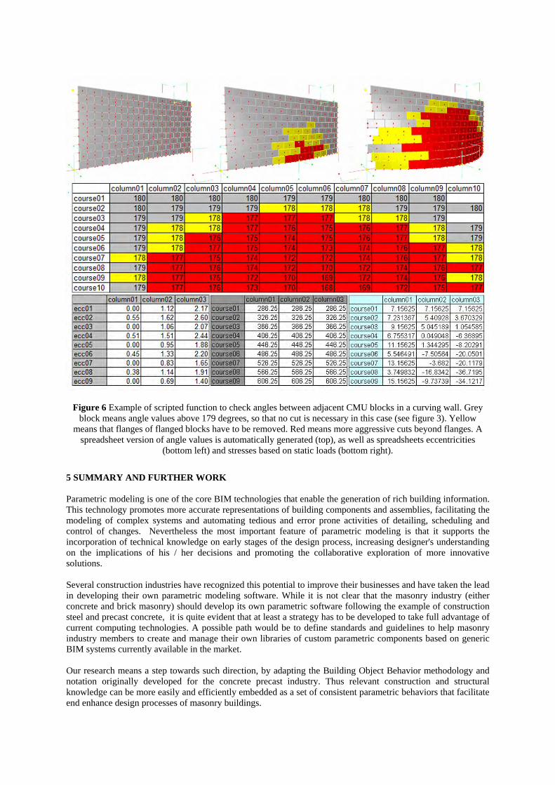
Figure 6 Example of scripted function to check angles between adjacent CMU blocks in a curving wall. Grey block means angle values above 179 degrees, so that no cut is necessary in this case (see figure 3). Yellow
means that flanges of flanged blocks have to be removed. Red means more aggressive cuts beyond flanges. A spreadsheet version of angle values is automatically generated (top), as well as spreadsheets eccentricities
(bottom left) and stresses based on static loads (bottom right).
5 SUMMARY AND FURTHER WORK Parametric modeling is one of the core BIM technologies that enable the generation of rich building information. This technology promotes more accurate representations of building components and assemblies, facilitating the modeling of complex systems and automating tedious and error prone activities of detailing, scheduling and control of changes. Nevertheless the most important feature of parametric modeling is that it supports the incorporation of technical knowledge on early stages of the design process, increasing designer's understanding on the implications of his / her decisions and promoting the collaborative exploration of more innovative solutions. Several construction industries have recognized this potential to improve their businesses and have taken the lead in developing their own parametric modeling software. While it is not clear that the masonry industry (either concrete and brick masonry) should develop its own parametric software following the example of construction steel and precast concrete, it is quite evident that at least a strategy has to be developed to take full advantage of current computing technologies. A possible path would be to define standards and guidelines to help masonry industry members to create and manage their own libraries of custom parametric components based on generic BIM systems currently available in the market. Our research means a step towards such direction, by adapting the Building Object Behavior methodology and notation originally developed for the concrete precast industry. Thus relevant construction and structural knowledge can be more easily and efficiently embedded as a set of consistent parametric behaviors that facilitate end enhance design processes of masonry buildings.
For this purpose masonry industry guidelines, specifically curved walls were used as sample rules that were described using BOB notation. The implementation of prototypes was done using Bentley's GenerativeComponents parametric system. Rules such as running bond pattern and rebar distribution were embedded at a generative level by means of scripted functions, while the verification of allowable angles between units and corbelling were included as checker functions to be applied a posteriori. This approach was considered useful to avoid the risk of over-constraining and interfering the free exploration of alternatives. Further work has to focus on increasing the number of construction rules to be embedded in both CMU units as well as overall building assemblies (besides walls, masonry pavements, slabs and roofs can be considered). While the partial prototypes developed so far worked well as independent models, extensive validation tests have to be done under the conditions of complete design processes. This challenge raises the problem of scalability of the model according to computer memory requirements. The conversion of external scripted functions as used so far, into hard-coded methods will contribute to improve the model's performance. Finally consistent interoperability between design parametric models and engineering analysis tools have to be studied in order to streamline the feedback cycles between engineers and architects. REFERENCES 1. Beall, C., New masonry products and materials. Prog. Struct. Engng Mater., 2000(2): p. 7. 2. Ramamurthy, K., Kunhanandan Nambiar E., K., Accelerated masonry construction: review and future
prospects, in Prog. Struct. Engng Mater. 2004. p. 9. 3. Eastman, C., New Methods of Architecture and Building, in ACADIA 2004. 2004. 4. Purcell T., G.J., Design and other types of fixation. Design Studies 17 1996(17): p. 363-383. 5. Buelow, P.v., An Intelligent Genetic Design Tool (IGDT). Applied to the Exploration of Architectural
Trussed Structural Systems, in Structural Engineering - Institute of Lightweight Structures and Construction 2007, Universität Stuttgart: Stuttgart p.227.
6. Eastman, C., Lee G., Sacks, R., Development of a Knowledge-Rich CAD System for the North American Precast Concrete Industry, in ACADIA, B.S. University, Editor. 2003, Ball State University: Ball State University, Muncie, IN. p. 16.
7. Lee, G., Sacks, R. and Eastman, C., Specifying Parametric Building Object Behavior (BOB) for a Building Information Modeling System. Automation in Construction, 2005(15): p. 19.
8. Sacks, R., Eastman, C. and Lee, G., Parametric 3D modeling in building construction with examples from precast concrete. Automation in Construction, 2003(13): p. 21.
9. Aish, R. Notes about Generative Components. SmartGeometry - ECAADE. 2005. Technical University of Lisbon, Portugal: ECAADE.
10. Bettig, B., Shah, J., Derivation of a standard set of geometric constraints for parametric modeling and data exchange. Computer Aided Design, 1999(33): p. 16.
12. Cavieres, A., Gentry, R., Parametric modeling of masonry assemblies. Design Computing and Cognition, 2008. Georgia Institute of Technology, United States.
11. NCMA, N.C.M.A., Typical Sizes and Shapes of Concrete Masonry Units, in TEK 2-1A Unit Properties (2002), Cemex, Editor. 2002, National Concrete Masonry Association: NCMA TEK. p. 4.
12. NCMA, N.C.M.A., Grouting Concrete Masonry Walls, in TEK 3-2A Construction (2005), Cemex, Editor. 2004, National Concrete Masonry Association: NCMA TEK. p. 6.
13. NCMA, N.C.M.A., Modular Layout of Concrete Masonry, in TEK 5-12 Details (2004), Cemex, Editor. 2004, National Concrete Masonry Association: NCMA TEK. p. 4.
14. NCMA, N.C.M.A. Tek Technical Information and Details NCMA e-TEK and e-Details Site FInder 2008 [cited 2008; Available from: http://www.ncma.org/resources/design/tek/Pages/default.aspx.
15. NCMA, N.C.M.A., Concrete Masonry Radial Wall Details, in TEK 5-10A Details (2006), Cemex, Editor. 2006, National Concrete Masonry Association: NCMA TEK. p. 4.
16. Shepherd, P,, and Hudson P., Parametric definition of Lansdowne Road Stadium. ASS Symposium 2007 - Structural Architecture. Venice, Italy.
11th Canadian Masonry Symposium, Toronto, Ontario, May 31- June 3, 2009
PARAMETRIC DESIGN, DETAILING AND STRUCTURAL ANALYSIS OF DOUBLY-CURVED LOAD-BEARING BLOCK WALLS
T. Russell Gentry1, Andres Cavieres2, and Tristan Al-Haddad3
1Associate Professor, College of Architecture, Georgia Institute of Technology, Atlanta, Georgia,
USA, [email protected] 2 Doctoral Candidate, College of Architecture, Georgia Institute of Technology, Atlanta,
Georgia, USA, [email protected] 3 Visiting Assistant Professor, College of Architecture, Georgia Institute of Technology, Atlanta,
Georgia, USA, [email protected] ABSTRACT This paper, explores the extent to which concepts of parametric modeling can be applied to support the design process of load-bearing masonry buildings. The research uses the concepts of building information modeling and parametric representation to capture and execute relevant constructive knowledge for the design of doubly-curved masonry walls. Prototype software has been developed to translate this knowledge into a set of explicit parametric rules and geometric constraints which “bound” the curvatures of the masonry walls to those with admissible construction and structural solutions. Rules for calculation of vertical and horizontal reinforcement placement of rebar in grouted cells and bond beams have been developed to allow for preliminary design of doubly-curved walls. The software operates within a CAD environment and provides real-time feedback on wall configuration and reinforcement as the model is built. The paper reviews the rules necessary for block wall description, including door and window openings, and focuses on the calculations necessary for preliminary structural design of doubly-curved load-bearing masonry walls. KEYWORDS: building information modeling, parametric modeling, concrete masonry units INTRODUCTION Masonry buildings and structures are often associated with conservative solutions and traditional architectural designs. Architects and engineers usually avoid innovative configurations or non-conventional building shapes because they are considered risky, difficult and expensive to solve. This perception clearly affects a more widespread adoption of block masonry, as well as its competitiveness with other construction systems. There are two related causes that complicate this situation: first the increasing lack of specialized knowledge about masonry requirements, limitations and possibilities and second, the lack of computational tools to effectively represent, explore and manipulate a masonry design model.

Despite the fact that the masonry industry and the research community have continuously moved forward with advances in new masonry unit types, structural analysis methods and more efficient construction processes there is a perception that the limits of masonry are not being challenged by architects [1], [2]. Current technical innovations are not being extensively transferred into design practice, and in most cases new masonry buildings continue to adopt conventional and rather conservative solutions. A number of misconceptions and prejudices among architects, such as the high cost of masonry construction and its limited formal possibilities threaten the competitiveness of masonry in relation to other structural systems. There are few digital tools available for designers to represent and explore innovated masonry configurations. In the absence of such tools what becomes costly is the amount of effort architects have to put on modeling and detailing a building with hundreds or probably thousands of masonry units. New Building Information Modeling technologies have been developed in recent years to handle similar complexities inherent to architectural design. They are already being used within the AEC industry for advanced design exploration, sophisticated engineering analysis and precise specification of building assemblies for fabrication. The parametric modeling capabilities of these technologies have facilitated the incorporation of technical knowledge about material behavior, fabrication and construction processes on early design stages, increasing architect's understanding of design implications and promoting successful innovations [3]. This research addresses this issue by focusing on the development of similar capabilities to promote the adoption of concrete masonry systems in contemporary design practice. For that purpose we explore methodologies to incorporate masonry construction knowledge into the design process by using state-of-art computational technologies. The goal is to improve the design and construction processes by supporting the creation, testing and evaluation of a higher number of design alternatives from the beginning. In this scenario an important emphasis will be put on formal variability and geometric complexity of building envelopes. Masonry units allow a wide and rich scope of configurations, and several types of formal results, whether in load-bearing mode or as cladding. This feature can be intensively explored by means of parametric modeling, making the representation of complex geometries and assemblies an easier and more realistic approach towards innovation in the design of masonry buildings. PARAMETRIC CONSTRUCTION OF CONCRETE BLOCK WALLS Object behavior in a parametric modeling environment is seen as the ability of a building component or assembly to respond to an internal or external stimulus preserving the original design intent. According to Sacks et al., this response occurs when the system is capable of taking automatic actions in order to “maintain the topological and geometrical consistency of the relationships within and between model objects” [4]. In this manner objects have to be modeled not only as they look but most importantly, as semantic relationships within a specific domain. However a major issue for the implementation of domain-specific BIM parametric solutions relates to the problem of how to specify and embed relevant design and engineering knowledge in a parametric modeling system. One of the main difficulties arises from the fact that much of this knowledge is tacit and difficult to represent.
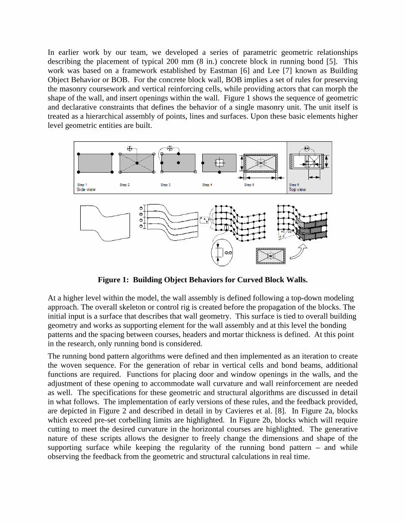
In earlier work by our team, we developed a series of parametric geometric relationships describing the placement of typical 200 mm (8 in.) concrete block in running bond [5]. This work was based on a framework established by Eastman [6] and Lee [7] known as Building Object Behavior or BOB. For the concrete block wall, BOB implies a set of rules for preserving the masonry coursework and vertical reinforcing cells, while providing actors that can morph the shape of the wall, and insert openings within the wall. Figure 1 shows the sequence of geometric and declarative constraints that defines the behavior of a single masonry unit. The unit itself is treated as a hierarchical assembly of points, lines and surfaces. Upon these basic elements higher level geometric entities are built.
Figure 1: Building Object Behaviors for Curved Block Walls.
At a higher level within the model, the wall assembly is defined following a top-down modeling approach. The overall skeleton or control rig is created before the propagation of the blocks. The initial input is a surface that describes that wall geometry. This surface is tied to overall building geometry and works as supporting element for the wall assembly and at this level the bonding patterns and the spacing between courses, headers and mortar thickness is defined. At this point in the research, only running bond is considered.
The running bond pattern algorithms were defined and then implemented as an iteration to create the woven sequence. For the generation of rebar in vertical cells and bond beams, additional functions are required. Functions for placing door and window openings in the walls, and the adjustment of these opening to accommodate wall curvature and wall reinforcement are needed as well. The specifications for these geometric and structural algorithms are discussed in detail in what follows. The implementation of early versions of these rules, and the feedback provided, are depicted in Figure 2 and described in detail in by Cavieres et al. [8]. In Figure 2a, blocks which exceed pre-set corbelling limits are highlighted. In Figure 2b, blocks which will require cutting to meet the desired curvature in the horizontal courses are highlighted. The generative nature of these scripts allows the designer to freely change the dimensions and shape of the supporting surface while keeping the regularity of the running bond pattern – and while observing the feedback from the geometric and structural calculations in real time.

Figure 2: Parametric Model: a) Cut Block Feedback Selected, and
b) Corbelling Feedback Selected. CONSTRUCTION AND STRUCTURAL REQUIREMENTS In the following text, the geometric, structural and detailing issues raised by the doubly-curved block walls, and the parametric approach to dealing with the issues are discussed. The generic wall in question is shown in Figure 3. The specific issues addressed are curvature in plan (which can be seen in Section P-P), curvature in section (which can be seen in Section S-S), accommodating internal reinforcement, insertion of door and window openings, and calculation of out-of-plane flexural capacity. In all cases we are dealing with a masonry wall, without intersections or pilasters. The wall can be curved in plan or section, but it cannot accommodate sloped bed joints.
P
P
j
Y
X
i
w
ecw
S
S
Figure 3: Doubly-Curved Block Wall.
WALL CURVATURE IN PLAN Concrete masonry in standard running bond construction accommodates curvature in plan quite well. Thomas Jefferson’s curved walls at the University of Virginia offer the prime example of
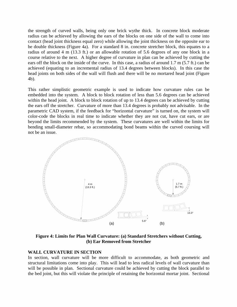
the strength of curved walls, being only one brick wythe thick. In concrete block moderate radius can be achieved by allowing the ears of the blocks on one side of the wall to come into contact (head joint thickness equal zero) while allowing the joint thickness on the opposite ear to be double thickness (Figure 4a). For a standard 8 in. concrete stretcher block, this equates to a radius of around 4 m (13.3 ft.) or an allowable rotation of 5.6 degrees of any one block in a course relative to the next. A higher degree of curvature in plan can be achieved by cutting the ears off the block on the inside of the curve. In this case, a radius of around 1.7 m (5.7 ft.) can be achieved (equating to an incremental radius of 13.4 degrees between blocks). In this case the head joints on both sides of the wall will flush and there will be no mortared head joint (Figure 4b). This rather simplistic geometric example is used to indicate how curvature rules can be embedded into the system. A block to block rotation of less than 5.6 degrees can be achieved within the head joint. A block to block rotation of up to 13.4 degrees can be achieved by cutting the ears off the stretcher. Curvature of more than 13.4 degrees is probably not advisable. In the parametric CAD system, if the feedback for “horizontal curvature” is turned on, the system will color-code the blocks in real time to indicate whether they are not cut, have cut ears, or are beyond the limits recommended by the system. These curvatures are well within the limits for bending small-diameter rebar, so accommodating bond beams within the curved coursing will not be an issue.
5.6°
13.3°
4 m(13.3 ft.)
1.7 m(5.7 ft.)
(a) (b)
Figure 4: Limits for Plan Wall Curvature: (a) Standard Stretchers without Cutting,
(b) Ear Removed from Stretcher WALL CURVATURE IN SECTION In section, wall curvature will be more difficult to accommodate, as both geometric and structural limitations come into play. This will lead to less radical levels of wall curvature than will be possible in plan. Sectional curvature could be achieved by cutting the block parallel to the bed joint, but this will violate the principle of retaining the horizontal mortar joint. Sectional
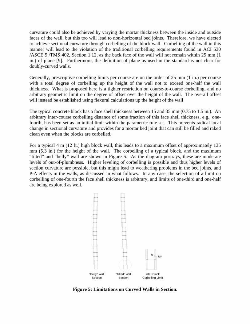
curvature could also be achieved by varying the mortar thickness between the inside and outside faces of the wall, but this too will lead to non-horizontal bed joints. Therefore, we have elected to achieve sectional curvature through corbelling of the block wall. Corbelling of the wall in this manner will lead to the violation of the traditional corbelling requirements found in ACI 530 /ASCE 5 /TMS 402, Section 1.12, as the back face of the wall will not remain within 25 mm (1 in.) of plane [9]. Furthermore, the definition of plane as used in the standard is not clear for doubly-curved walls. Generally, prescriptive corbelling limits per course are on the order of 25 mm (1 in.) per course with a total degree of corbelling up the height of the wall not to exceed one-half the wall thickness. What is proposed here is a tighter restriction on course-to-course corbelling, and no arbitrary geometric limit on the degree of offset over the height of the wall. The overall offset will instead be established using flexural calculations up the height of the wall The typical concrete block has a face shell thickness between 15 and 35 mm (0.75 to 1.5 in.). An arbitrary inter-course corbelling distance of some fraction of this face shell thickness, e.g., one-fourth, has been set as an initial limit within the parametric rule set. This prevents radical local change in sectional curvature and provides for a mortar bed joint that can still be filled and raked clean even when the blocks are corbelled. For a typical 4 m (12 ft.) high block wall, this leads to a maximum offset of approximately 135 mm (5.3 in.) for the height of the wall. The corbelling of a typical block, and the maximum “tilted” and “belly” wall are shown in Figure 5. As the diagram portrays, these are moderate levels of out-of-plumbness. Higher leveling of corbelling is possible and thus higher levels of section curvature are possible, but this might lead to weathering problems in the bed joints, and P-Δ effects in the walls, as discussed in what follows. In any case, the selection of a limit on corbelling of one-fourth the face shell thickness is arbitrary, and limits of one-third and one-half are being explored as well.
fs/4
"Belly" Wall Section
"Tilted" Wall Section
Inter-BlockCorbelling Limit
fs
Figure 5: Limitations on Curved Walls in Section.
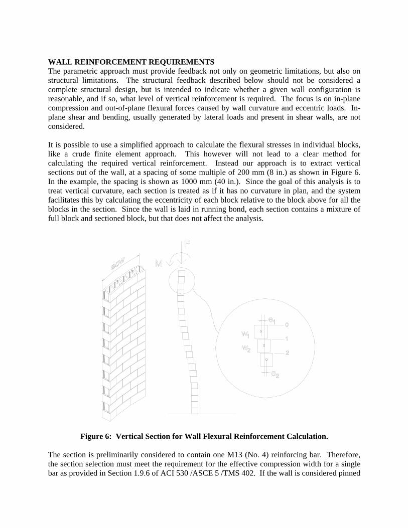
WALL REINFORCEMENT REQUIREMENTS The parametric approach must provide feedback not only on geometric limitations, but also on structural limitations. The structural feedback described below should not be considered a complete structural design, but is intended to indicate whether a given wall configuration is reasonable, and if so, what level of vertical reinforcement is required. The focus is on in-plane compression and out-of-plane flexural forces caused by wall curvature and eccentric loads. In-plane shear and bending, usually generated by lateral loads and present in shear walls, are not considered. It is possible to use a simplified approach to calculate the flexural stresses in individual blocks, like a crude finite element approach. This however will not lead to a clear method for calculating the required vertical reinforcement. Instead our approach is to extract vertical sections out of the wall, at a spacing of some multiple of 200 mm (8 in.) as shown in Figure 6. In the example, the spacing is shown as 1000 mm (40 in.). Since the goal of this analysis is to treat vertical curvature, each section is treated as if it has no curvature in plan, and the system facilitates this by calculating the eccentricity of each block relative to the block above for all the blocks in the section. Since the wall is laid in running bond, each section contains a mixture of full block and sectioned block, but that does not affect the analysis.
Figure 6: Vertical Section for Wall Flexural Reinforcement Calculation.
The section is preliminarily considered to contain one M13 (No. 4) reinforcing bar. Therefore, the section selection must meet the requirement for the effective compression width for a single bar as provided in Section 1.9.6 of ACI 530 /ASCE 5 /TMS 402. If the wall is considered pinned
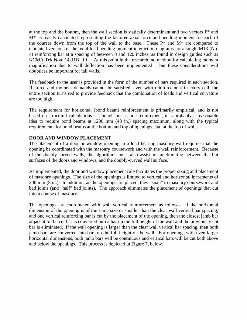
at the top and the bottom, then the wall section is statically determinant and two vectors P* and M* are easily calculated representing the factored axial force and bending moment for each of the courses down from the top of the wall to the base. These P* and M* are compared to tabulated versions of the axial load bending moment interaction diagrams for a single M13 (No. 4) reinforcing bar at a spacing of between 8 and 120 inches, as found in design guides such as NCMA Tek Note 14-11B [10]. At this point in the research, no method for calculating moment magnification due to wall deflection has been implemented – but these considerations will doubtless be important for tall walls. The feedback to the user is provided in the form of the number of bars required in each section. If, force and moment demands cannot be satisfied, even with reinforcement in every cell, the entire section turns red to provide feedback that the combination of loads and vertical curvature are too high. The requirement for horizontal (bond beam) reinforcement is primarily empirical, and is not based on structural calculations. Though not a code requirement, it is probably a reasonable idea to require bond beams at 1200 mm (48 in.) spacing maximum, along with the typical requirements for bond beams at the bottom and top of openings, and at the top of walls. DOOR AND WINDOW PLACEMENT The placement of a door or window opening in a load bearing masonry wall requires that the opening be coordinated with the masonry coursework and with the wall reinforcement. Because of the doubly-curved walls, the algorithms must also assist in ameliorating between the flat surfaces of the doors and windows, and the doubly-curved wall surface. As implemented, the door and window placement rule facilitates the proper sizing and placement of masonry openings. The size of the openings is limited to vertical and horizontal increments of 200 mm (8 in.). In addition, as the openings are placed, they “snap” to masonry coursework and bed joints (and “half” bed joints). The approach eliminates the placement of openings that cut into a course of masonry. The openings are coordinated with wall vertical reinforcement as follows. If the horizontal dimension of the opening is of the same size or smaller than the clear wall vertical bar spacing, and one vertical reinforcing bar is cut by the placement of the opening, then the closest jamb bar adjacent to the cut bar is converted into a bar up the full height of the wall and the previously cut bar is eliminated. If the wall opening is larger than the clear wall vertical bar spacing, then both jamb bars are converted into bars up the full height of the wall. For openings with even larger horizontal dimensions, both jamb bars will be continuous and vertical bars will be cut both above and below the openings. This process is depicted in Figure 7, below.
Algorithm to insert and adjust new vertically reinforced cells
Vertical reinforcement at 1000 mm [40 in.] centers
Algorithm that planar window frame will fit within doubly curved wall
Algorithm to insert and adjust new vertically reinforced cells
Vertical reinforcement at 1000 mm [40 in.] centers
Algorithm that planar window frame will fit within doubly curved wall
Figure 7: Algorithms for Creating Openings in Walls.
Finally, the system must verify that an opening within the curved wall, is “planar enough” to accommodate a planar door or window frame. The thickness of both the wall and the window frame are known – and the thickness of the window frame is usually 50 to 75 mm (2 to 3 in.) thinner than the wall thickness. Consequently, the parametric relationship between opening and frame can be tracked, so that openings that violate the “plane within a surface” restrictions are coded as the openings are placed, alerting the user to the fact that the door or window will not fit properly in this location – or, that the wall curvature will need to be changed to accommodate the door or window. CONCLUSION The methodology presented above is simplified so that all calculations can be updated continuously as the wall is varied with the CAD environment and the Building Information Model is constructed. The purpose of the system as described acts primarily in the early stages of design, before the architect seeks the advice of a structural engineer. The system functions then as a tool to validate, shape and bound architectural decisions. The goal is to provide architects with a tool to design complex masonry walls with confidence to know that the walls are both structurally feasible and constructible. ACKNOWLEDGEMENTS This research is funded by the NCMA Education and Research Foundation. The support and guidance of the foundation is gratefully acknowledged. The guidance and leadership of Professor Charles Eastman at Georgia Tech is also gratefully acknowledged.

REFERENCES 1. Beall, C. (2000) “New Masonry Products and Materials”, Vol. 2, No. 3, Progress in
Structural Engineering and Materials, pp. 296-303. 2. Beall, C. & Jaffe, R. (2002) Concrete and Masonry Databook, New York: McGraw Hill. 3. Bettig, B. & Shah, J. (2003). “Derivation of a Standard set of Geometric Constraints for
Parametric Modeling and Data Exchange.” Computer-Aided Design, 33, 17-33. 4. Sacks, R., Eastman, C. & Lee, G. (2003). “Parametric 3D Modeling in Building Construction
with Examples from Precast Concrete.” Automation in Construction, 13, 291– 312. 5. Cavieres, Andres, Gentry, Russell, and Al-Haddad, Tristan, 2008, “Parametric Design of
Masonry Buildings: Embedding Construction Knowledge into Design Models”, Proceedings, 8th International Seminar on Structural Masonry, Istanbul, Turkey, November 5-7, 2008.
6. Eastman, C., Lee G. &Sacks, R. (2003). “Development of a Knowledge-Rich CAD System
for the North American Precast Concrete Industry.” Proceeding of the 23rd Conference of the Association for Computer Aided Design in Architecture Acadia (pp. 16). Muncie, IN: K. Klinger.
7. Lee, G., Sacks, R. & Eastman, C. (2005). “Specifying Parametric Building Object Behavior
(BOB) for a Building Information Modeling System.” Automation in Construction, 15, 758 – 776.
8. Cavieres, Andres, Gentry, Russell, and Al-Haddad, Tristan (2009), “Rich Knowledge
Parametric Tools for Concrete Masonry Design: Automation of Preliminary Structural Analysis, Detailing and Specifications”, Proceedings, 26th International Symposium on Automation and Robotics in Construction (ISARC), Austin, Texas.
9. Building Code Requirements and Specifications for Masonry Structures, (2005) MSJC (TMS
402-08/ACI 530-08/ASCE 5-08 and TMS 602-08/ACI 530.1-08/ASCE 6-08), Masonry Standards Joint Committee, The Masonry Society.
10. National Concrete Masonry Association. (2003), “Strength Design Of Concrete Masonry
Walls For Axial Load & Flexure,” TEK 14-11B, NCMA, Herndon, Virginia.