Embed Size (px)
Citation preview

GEORGIA DEPARTMENT OF TRANSPORTATION
GDOT FIELD DATA COLLECTION SYSTEM
VERSION 4.0
Prepared for: Georgia Department of Transportation 276 Memorial Drive, SW Atlanta, Georgia 30303-3743 Prepared by: Georgia Department of Transportation Office of IT Applications 276 Memorial Drive, SW Atlanta, Georgia 30303-3743 Document Number: 01.00Version Number: 01.00
FDCS Georgia Department of Transportation
TABLE OF CONTENTS
1 OVERVIEW .............................................................................................................................................................. 6 1.1 TECHNICAL INFORMATION................................................................................................................................. 7
2 INSTALLATION INSTRUCTIONS...................................................................................................................... 8 2.1 PROGRAM REQUIREMENTS ................................................................................................................................ 8 2.2 SETUP ................................................................................................................................................................. 8 2.3 TERMINOLOGY ................................................................................................................................................... 9
3 UPDATES ................................................................................................................................................................ 10 3.1.1 DOT 553 ..................................................................................................................................................... 10 3.1.2 Gauge Calibration...................................................................................................................................... 10 3.1.3 OMR Link ................................................................................................................................................... 10 3.1.4 Web Upload................................................................................................................................................ 10 3.1.5 Asphalt Rating Summary............................................................................................................................ 10 3.1.6 Asphalt Report ............................................................................................................................................ 10 3.1.7 Asphalt Plant Summary.............................................................................................................................. 10 3.1.8 DOT 159 Report ......................................................................................................................................... 10 3.1.9 Backup Process .......................................................................................................................................... 10
4 USING THE FDCS ................................................................................................................................................. 11 4.1 OPENING A FORM FOR DATA ENTRY................................................................................................................. 13 4.2 GENERAL DATA ENTRY................................................................................................................................... 14 4.3 GENERAL FORM ENTRY................................................................................................................................... 17
4.3.1 Editing Menus: ........................................................................................................................................... 17 4.3.1.1 File:..................................................................................................................................................................... 17 4.3.1.2 Edit: .................................................................................................................................................................... 17 4.3.1.3 View: .................................................................................................................................................................. 17 4.3.1.4 Filter: .................................................................................................................................................................. 18 4.3.1.5 Sort: .................................................................................................................................................................... 18 4.3.1.6 Help: ................................................................................................................................................................... 18
4.4 DOT 152 - WATER TURBIDITY ENTRY FORM ................................................................................................. 19 4.5 DOT 159 - ASPHALTIC CONCRETE LOT WORKSHEET..................................................................................... 20
4.5.1 Header Tab................................................................................................................................................. 20 4.5.2 Tests Tab..................................................................................................................................................... 21 4.5.3 Samples....................................................................................................................................................... 21 4.5.4 Pay Factors ................................................................................................................................................ 22
4.6 DOT 160 - ASPHALTIC CONCRETE COMPARISON REFEREE............................................................................ 23 4.7 DOT 161 - ASPHALTIC CONCRETE QUALITY ASSURANCE ............................................................................. 25 4.8 OMR 149 - PORTLAND CEMENT...................................................................................................................... 26 4.9 DOT 176 - THICKNESS MEASUREMENTS ........................................................................................................ 27 4.10 DOT 553 - ROADWAY COMPACTION REPORT................................................................................................. 29
4.10.1 Header Info Tab ......................................................................................................................................... 29 4.10.2 Moisture Data............................................................................................................................................. 30 4.10.3 Family of Curves Data tab:........................................................................................................................ 30 4.10.4 Compaction Data ....................................................................................................................................... 30
4.11 DOT 640 - AGGREGATE QUALITY DATA ENTRY FORM.................................................................................. 31 4.12 DOT 641 - AGGREGATE QUANTITY FORM...................................................................................................... 33 4.13 DOT 386 - ASPHALTIC COMPARISON/COMPACTION VOID ............................................................................. 34 4.14 DOT 168 - CONCRETE QUALITY COMPARISON............................................................................................... 36 4.15 DOT 163 - FIELD PAINT THICKNESS ............................................................................................................... 38 4.16 DOT 169 - MISCELLANEOUS ........................................................................................................................... 39 4.17 DOT 162 - BRIDGE PAINTING CONDITIONS..................................................................................................... 40 4.18 DOT 165 - GALVANIZED COATING ................................................................................................................. 41
Document Number: 01.00T Page 2 of 70 Version Number: 01.00
FDCS Georgia Department of Transportation
4.19 DOT 116 - PIPE CERTIFICATION AND QUALITY .............................................................................................. 42 4.19.1 Corrugated Aluminum or Steel .................................................................................................................. 43 4.19.2 Concrete Pipe ............................................................................................................................................. 43
4.20 DOT 150 - CONTROL STRIP AND ASPHALTIC COMPACTION........................................................................... 44 4.21 RANDOM NUMBER SAMPLING UTILITY........................................................................................................... 46 4.22 GENERIC RANDOM NUMBER GENERATOR ...................................................................................................... 47 4.23 PRINTING AGGREGATE DATA AND STATISTICAL REPORTS ............................................................................ 48 4.24 PRINTING ASPHALT REPORTS .......................................................................................................................... 49 4.25 IMPORTING EXTERNAL DATA .......................................................................................................................... 50 4.26 BACKING UP YOUR DATA................................................................................................................................ 51
4.26.1 Database Backup – New Backup ............................................................................................................... 52 4.26.1.1 Database Backup – Append ............................................................................................................................... 56
4.26.2 Database Backup – Restore ....................................................................................................................... 58 4.27 WEB UPLOAD PROCESS ................................................................................................................................... 62
5 MISC OPTIONS ..................................................................................................................................................... 65 5.1 PASSWORD RETRIVAL...................................................................................................................................... 65 5.2 VIEW LOG ........................................................................................................................................................ 66 5.3 UPDATE ACCOUNT........................................................................................................................................... 66
6 UPLOADING CORRECTED COPIES............................................................................................................... 67
7 TROUBLESHOOTING ......................................................................................................................................... 68 7.1 MODEM DOES NOT DIAL................................................................................................................................. 68 7.2 MODEM DIALS, BUT THERE IS NO ANSWER.................................................................................................... 68 7.3 MODEM CONNECTS BUT TEXT IS GARBLED..................................................................................................... 68 7.4 MODEM HANGS UP UNEXPECTEDLY ............................................................................................................... 68 7.5 UNABLE TO OPEN COMM PORT ........................................................................................................................ 68 7.6 EVERYTHING WAS WORKING FINE, BUT SUDDENLY THE MODEM WON'T WORK.............................................. 69
8 CONTACTING THE GDOT FOR SUPPORT................................................................................................... 70
Document Number: 01.00T Page 3 of 70 Version Number: 01.00
FDCS Georgia Department of Transportation
TABLE OF FIGURES
Figure 1 - System Setup............................................................................................................................................................... 8 Figure 2 - Installation Type ........................................................................................................................................................ 9 Figure 3 - FDCS Icon.................................................................................................................................................................. 9 Figure 4 - Path to FDCS Application ...................................................................................................................................... 9 Figure 5 - Main Menu................................................................................................................................................................11 Figure 6 - Example of form .....................................................................................................................................................13 Figure 7 - Multiple Records......................................................................................................................................................13 Figure 8 – Records .....................................................................................................................................................................14 Figure 9 - Open Record ............................................................................................................................................................14 Figure 10 - Text Box..................................................................................................................................................................15 Figure 11 - Result Box...............................................................................................................................................................15 Figure 12 - Drop Down Box ...................................................................................................................................................15 Figure 13 - Check Box...............................................................................................................................................................15 Figure 14 - Tabs..........................................................................................................................................................................15 Figure 15 - Help Field................................................................................................................................................................15 Figure 16 - Toolbar ....................................................................................................................................................................16 Figure 17 - Units.........................................................................................................................................................................16 Figure 18 - Ready To Send.......................................................................................................................................................16 Figure 19 - Print current data...................................................................................................................................................16 Figure 20 - Form.........................................................................................................................................................................17 Figure 21 - Water Turbidity Form ..........................................................................................................................................19 Figure 22 - Asphaltic Concrete Lot Worksheet ...................................................................................................................20 Figure 23 - Asphaltic Concrete Comparison Referee.........................................................................................................23 Figure 24 - Asphaltic Concrete Quality Assurance .............................................................................................................25 Figure 25 - Portland Cement....................................................................................................................................................26 Figure 26 - Thickness Measurements.....................................................................................................................................27 Figure 27 - Roadway Compaction Report ............................................................................................................................29 Figure 28 - Aggregate Quality Data Entry ............................................................................................................................31 Figure 29 - Aggregate Quantity Form....................................................................................................................................33 Figure 30 - Asphaltic Comparison Compaction..................................................................................................................34 Figure 31 - Concrete Quality Comparison............................................................................................................................36 Figure 32 - Field Paint Thickness............................................................................................................................................38 Figure 33 – Miscellaneous ........................................................................................................................................................39 Figure 34 - Bridge Painting Condition...................................................................................................................................40 Figure 35 - Galvanized Coating...............................................................................................................................................41 Figure 36 - Control Strip and Asphaltic Compaction.........................................................................................................44 Figure 37 - Generic Random Number Generator...............................................................................................................47 Figure 38 - Aggregate Reports.................................................................................................................................................48 Figure 39 - Printing Asphalt Reports .....................................................................................................................................49 Figure 40 - FDCS Backup System ..........................................................................................................................................51 Figure 41 - Transaction Mode Screen....................................................................................................................................51 Figure 42 - Database Backup Selected...................................................................................................................................52 Figure 43 - Backup Options.....................................................................................................................................................52 Figure 44 - Backup File .............................................................................................................................................................53 Figure 45 - File Name................................................................................................................................................................53 Figure 46 - File Location...........................................................................................................................................................54 Figure 47 - Reports Selection...................................................................................................................................................54 Figure 48 – Backup Customization ........................................................................................................................................55 Figure 49 - Back Up Conditions .............................................................................................................................................55 Figure 50 - Confirmation of Back up.....................................................................................................................................55
Document Number: 01.00T Page 4 of 70 Version Number: 01.00
FDCS Georgia Department of Transportation
Figure 51 - File Location...........................................................................................................................................................56 Figure 52 - Reports Selection...................................................................................................................................................56 Figure 53 - Backup Customization .........................................................................................................................................57 Figure 54 – Complete Screen...................................................................................................................................................57 Figure 55 - FDCS Backup System ..........................................................................................................................................58 Figure 56 - Transaction Mode Screen....................................................................................................................................58 Figure 57 - File Location - Restore.........................................................................................................................................59 Figure 58 - Reports Restore .....................................................................................................................................................59 Figure 59 - Restore Customization.........................................................................................................................................60 Figure 60 - Restore verification ...............................................................................................................................................60 Figure 61 - Final Confirmation................................................................................................................................................60 Figure 62 – Complete Screen...................................................................................................................................................61 Figure 63 - Upload Options .....................................................................................................................................................62 Figure 64 - Start screen..............................................................................................................................................................62 Figure 65 - Log In screen..........................................................................................................................................................63 Figure 66 - Data Upload Page .................................................................................................................................................63 Figure 67 – Data Upload File screen......................................................................................................................................64 Figure 68 - Upload Confirmation ...........................................................................................................................................64 Figure 69 - Log In screen..........................................................................................................................................................65 Figure 70 - Password Retrieveal Screen.................................................................................................................................65 Figure 71 - View Log.................................................................................................................................................................66 Figure 72 - Update Account Information .............................................................................................................................66
Document Number: 01.00T Page 5 of 70 Version Number: 01.00

FDCS Georgia Department of Transportation
1 Overview
The GDOT Field Data Collection system is a program that assists GDOT testing technicians and certified contractor technicians in entering and sending field test data to the GDOT and enables them to perform statistical analysis on their own local data. The GDOT Field Data Collection System V3.31 has entry forms for: 1. 152 – Water Turbidity
2. 159 – Asphaltic Concrete Lot Worksheet
3. 160 – Asphaltic Concrete Comparison / Referee
4. 161 – Asphaltic Concrete Quality Assurance
5. OMR-049 – Portland Cement
6. 176 – Thickness Measurement
7. 553 – Roadway Compaction
8. 640 – Aggregate Producer Quality
9. 641 – Aggregate Producer Quantity
10. 386 – Asphaltic Comparison Compaction / Void
11. 168 – Concrete Quality Comparision
12. 163 – Field Paint Thickness
13. 162 – Bridge Painting Conditions
14. 165 – Galvanized Coating
15. 169 – Miscellaneous
16. 116 – Pipe Certification and Quality
17. 150 – Control Strip and Asphaltic Compaction
Data that is sent to the GDOT using the Field Data Collection system is stored in the GDOT’s Field Data Server Database located at the Office of Materials and Research. Once there, designated GDOT personal verify data, perform statistical analysis on the data as a whole, and generate ratings.
Document Number: 01.00T Page 6 of 70 Version Number: 01.00
FDCS Georgia Department of Transportation
1.1 Technical Information
Additional technical information regarding the operation of this program can be found on the CD-ROM in the DOCS folder. If you did not receive this program on CD-ROM then they can be downloaded from the Internet on the update page mentioned in the next section.
Document Number: 01.00T Page 7 of 70 Version Number: 01.00

FDCS Georgia Department of Transportation
2 Installation Instructions
2.1 Program Requirements
For the best results you should have at least a 166mhz CPU, 32megs of ram, 30 megs of free hard drive space, a monitor running at 800x600 16-bit color with 75 hertz refresh rate, and Microsoft Windows 95 or compatible (Windows NT 4 needs service pack 4 or later). This program requires a modem configured on COM ports 1, 2, 3 or 4 and an analog telephone line for uploading to the GDOT. Important: If this software is to be installed on a computer that belongs to your company, you must contact your computer systems administrator and get permission to install it or have them install it for you. Your administrator will also need to make sure that you have write access to the GDOTDCS.MDE file.
2.2 Setup
1. While connected to the internet, go to the following web page:
http://tomcat2.dot.state.ga.us/fdcs/upgrade/fdcsupgrade2.cfm 2. Select the appropriate download for your machine and download the instructions first.
3. Then download the corresponding help files associated with your download.
4. If you received the software on a CD, close any running applications and insert your CD in to your CD
drive. On the “Welcome to GDOT Software” screen, click on “Run Setup”
5. At the setup welcome screen, click “Continue”. You will be prompted for an installation folder. Unless you
have special requirements for your system, you should accept the default location of C:\Program Files\GDOTDCS. Continue by clicking “OK”.
Figure 1 - System Setup
Document Number: 01.00T Page 8 of 70 Version Number: 01.00
FDCS Georgia Department of Transportation
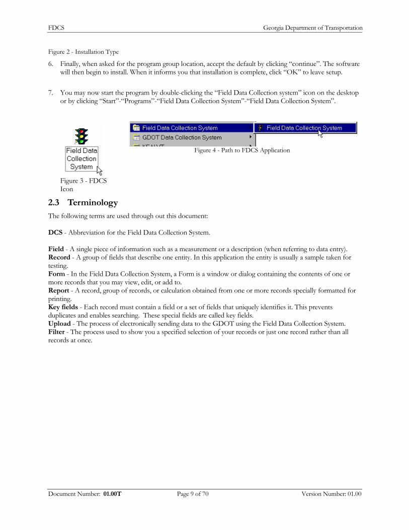
Figure 2 - Installation Type
6. Finally, when asked for the program group location, accept the default by clicking “continue”. The software will then begin to install. When it informs you that installation is complete, click “OK” to leave setup.
7. You may now start the program by double-clicking the “Field Data Collection system” icon on the desktop
or by clicking “Start”-“Programs”-“Field Data Collection System”-“Field Data Collection System”.
Figure 3 - FDCS Icon
Figure 4 - Path to FDCS Application
2.3 Terminology
The following terms are used through out this document: DCS - Abbreviation for the Field Data Collection System. Field - A single piece of information such as a measurement or a description (when referring to data entry). Record - A group of fields that describe one entity. In this application the entity is usually a sample taken for testing. Form - In the Field Data Collection System, a Form is a window or dialog containing the contents of one or more records that you may view, edit, or add to. Report - A record, group of records, or calculation obtained from one or more records specially formatted for printing. Key fields - Each record must contain a field or a set of fields that uniquely identifies it. This prevents duplicates and enables searching. These special fields are called key fields. Upload - The process of electronically sending data to the GDOT using the Field Data Collection System. Filter - The process used to show you a specified selection of your records or just one record rather than all records at once.
Document Number: 01.00T Page 9 of 70 Version Number: 01.00
FDCS Georgia Department of Transportation
3 Updates
The following updates have been added to version FDCS v 4.0:
3.1.1 DOT 553
The DOT 553 Report form features one new field entitled ‘Contractor Code’.
3.1.2
3.1.3
3.1.4
Gauge Calibration
The new Gauge Calibration screen features four more decimal places to the gauge factors as well as corrected default values in the density and moisture blocks.
OMR Link
The new OMR User Training Manual button links to the OMR User Training Manual.
Web Upload
The Web Upload process replaces the current BBS upload process.
3.1.5
3.1.6
Asphalt Rating Summary
The new Asphalt Rating Summary report shows a summary of all the data for a given plant number.
Asphalt Report
The new Asphalt Reports features two new reports (Yearly and Monthly).
3.1.7
3.1.8
Asphalt Plant Summary
The new Asphalt Plant Summary report features the ranges of dates on the actual report.
DOT 159 Report
The new 159 report features input fields for the Daily Tonnage.
3.1.9 Backup Process
There is a new backup/restore process for your existing or new data.
Document Number: 01.00T Page 10 of 70 Version Number: 01.00

FDCS Georgia Department of Transportation
4 Using the FDCS
When you start the Field Data Collection System, the first thing you will see is the Main Menu. The Main menu provides a “pallet” of entry forms and utilities for each testing group that uses this application. Click on the tab with the name of your testing group to see just the reports that apply to your group.
Figure 5 - Main Menu From here you have the following options: (depending on which tab you selected) ● DOT 152 - Water Turbidity entry form. ● DOT 159 – Asphaltic Concrete Lot Worksheet entry form. (English and metric units) ● DOT 160 – Asphaltic Concrete Comparison / Referee entry form. ● DOT 161 – Asphaltic Concrete Quality Entry form. ● OMR-049 – Portland Cement entry sheet. ● DOT 176 – Thickness Measurement entry form (English and metric units) ● DOT 553 – Roadway Compaction Form (English and metric units) ● DOT 640 - Aggregate Producer Quality data entry form. ● DOT 641 - Aggregate Producer Quantify data entry form. ● DOT 386 – Asphaltic Comparison Compaction / Void data entry form. (English and metric units) ● DOT 168 – Concrete Quality Comparision data entry form. (English and metric units) ● DOT 163 – Field Paint Thickness data entry form. (English and metric units) ● DOT 162 – Bridge Painting Conditions data entry form. (English and metric units) ● DOT 165 – Galvanized Coating data entry form. (English and metric units) ● DOT 169 – Miscellaneous data entry form ● DOT 116 – Pipe Certification and Quality data entry form. (English and metric units) ● DOT 150 – Control Strip and Asphaltic Compaction data entry form. (English and metric units)
Document Number: 01.00T Page 11 of 70 Version Number: 01.00

FDCS Georgia Department of Transportation
● Asphalt Reports and Printouts – Clicking this button will open the Asphalt Reports window which contains options for generating printed statistical reports relating to the DOT 159 Asphaltic Concrete Lot Worksheet.
● Aggregate Reports – Clicking this button will open the Aggregate Reports dialog box which contains options for generating printed statistical reports relating to the DOT 640 and DOT 641 reports.
● Edit Gauge Factors – Clicking this button will show you the gauge factors used for the DOT 553 Roadway Compaction form. You may also edit them if necessary, but usually you will use the “Update Gauge Factors” to get the correct factors.
● Update Gauge Factors – Clicking this button will update the list of gauge factors with one provided on an update disk.
● Import Custom Data – This is a special function for Aggregate producers who use their own custom software for data collection. It enables them to automatically import data from their system and send it to the GDOT.
● Random Number Sampling Utility – Users of the 159 form use this to determine which loads in a lot are randomly sampled.
● Generic Random Number Generator – This utility is a general-purpose random number generator for tests that use random sampling.
● Upload to GDOT – Click this button to start the process of sending entered and modified data to the GDOT electronically.
● Backup/Restore – Clicking this button will open the backup/restore window that enables you to make a copy of your data on floppy disk or re-load old data.
● Check for updates on the GDOT web site – Clicking this button opens your default web browser and takes you to the GDOT DCS download web page. (This requires an Internet connection). You should check this page regularly for updates that may add functionality to the program or fix problems.
● Read / Print Manual – Clicking this button opens this manual. This requires a word processor or viewer that can open Microsoft Word documents. (A viewer is included on the CD, and can be downloaded from the Internet.)
● Load Contract IDs – Contract ID fields on all entry forms have a pull down box that lets you select from a list of current contract IDs. (You can still enter whatever you want). You must keep this list of contract IDs up to date. To update the list, download the CONTRACT.DAT file from the updates web site listed above to a folder on your computer. Then click this button and select the CONTRACT.DAT file in the file list and click ok. The file will load in to your copy of the data collection system. The list on the web site is updated twice a month.
Document Number: 01.00T Page 12 of 70 Version Number: 01.00

FDCS Georgia Department of Transportation
4.1 Opening a form for data entry
Figure 6 - Example of form 1. To open a form for data entry, click on the desired form.
2. With the exception of the 640, 641, and OMR-049, which are continuous forms (that is you can see more than one record at a time), you must specify which record you wish to enter.
Figure 7 - Multiple Records 3. Enter the values you wish to search for or use to create a new record. Then click one of the following
buttons:
Create/Edit – If you entered values for all fields you will be taken to the record if it exists. If it does not, a new one is created automatically. (Note: When using this method new blank records are immediately created and stored. To remove this record you must delete it.) If you left one or more fields blank and more than one record matching the entered values is found, you will be prompted to select a record from a list. Search All - Clicking this brings up a list of all records you have entered. This is the same as if you left all of the prompted fields blank and clicked create/edit. Open All - Opens the data entry form but lets you work with all records at once instead of just one at a time. You may browse all of the records using the navigation buttons at the bottom of the entry form. This also allows you to use the “find” option on the form and apply your own filters. Cancel – Returns you to the main menu.
Document Number: 01.00T Page 13 of 70 Version Number: 01.00
FDCS Georgia Department of Transportation
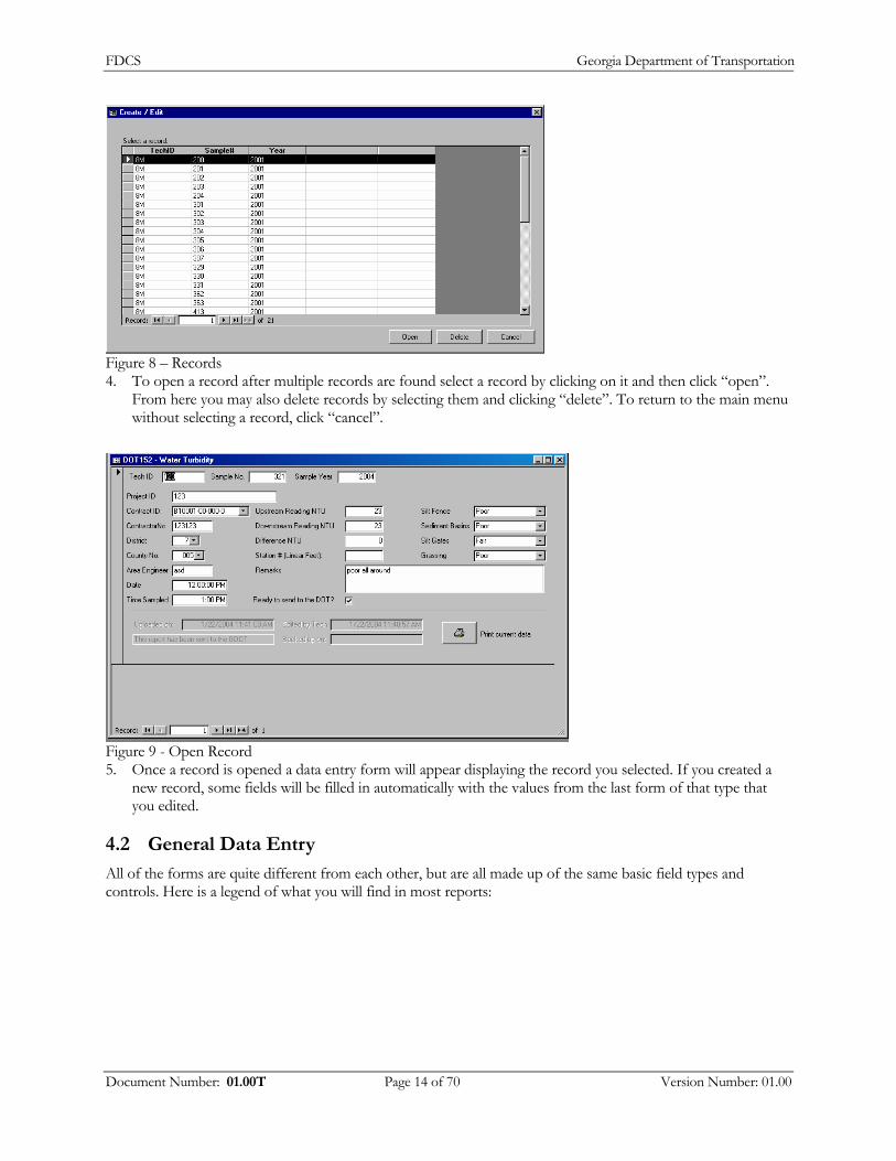
Figure 8 – Records 4. To open a record after multiple records are found select a record by clicking on it and then click “open”.
From here you may also delete records by selecting them and clicking “delete”. To return to the main menu without selecting a record, click “cancel”.
Figure 9 - Open Record 5. Once a record is opened a data entry form will appear displaying the record you selected. If you created a
new record, some fields will be filled in automatically with the values from the last form of that type that you edited.
4.2 General Data Entry
All of the forms are quite different from each other, but are all made up of the same basic field types and controls. Here is a legend of what you will find in most reports:
Document Number: 01.00T Page 14 of 70 Version Number: 01.00

FDCS Georgia Department of Transportation
Figure 10 - Text Box
Text Box: This is the most common field on a form. When the cursor appears in it you may type in your data using the keyboard. Disabled text boxes appear grayish and will not allow you to edit them. Important: For test data, leave fields blank to indicate that a test was not run or a value was not collected. Entering a zero indicates that the test was run and a value of zero was measured.
Figure 11 - Result Box
Result Box: Usually these are calculated fields, and can not be edited.
Figure 12 - Drop Down Box
Drop-down box: Drop-down boxes are like text boxes but let you select from a menu of options. To display this menu, click on the down-triangle at the right of the box. Depending on its function a drop-down box may limit what you can enter to what is available in the list.
Figure 13 - Check Box
Check box: These boxes can be either checked or unchecked. Clicking on the check box changes its condition. (Pressing the space bar while it is selected also changes its value)
Figure 14 - Tabs
Tabs: Some forms have more than one page. These forms have tabs at the top of the page that represents each page of the form. Clicking on a tab will bring the page to the top.
Figure 15 - Help Field
Help Bar: The help bar displays a brief explanation of what you should enter in the currently selected field, and may include an example.
Document Number: 01.00T Page 15 of 70 Version Number: 01.00

FDCS Georgia Department of Transportation
Figure 16 - Toolbar
Toolbar: The tool bar contains commonly used option buttons that you can click on while editing data in a form. “New Record” will show a blank line or form for data entry, “Delete Record” deletes the currently selected record, “Save Record” immediately saves the data in the line or form that you are editing (Note: Data is automatically saved when you move to a new line in a data sheet view or a new page in a form view). “Find” enables you to search all currently available records for a piece of data. Note: If the form has been opened to create or edit just one record the “new record” button will be grayed out. Additionally performing a “find” will yield no results, as it will search only the current record rather than all records on file.
Figure 17 - Units
Units: All fields for measurements specify a unit. (In this example it is inches). The value you enter must be in the specified unit. Some entry forms have metric versions in which the only differences are the units. It is critical that you are aware of what unit you must use. The DCS stores all measurements in a common set of units, which enables you to view the same data using both metric and English forms.
Figure 18 - Ready To Send
Ready to send: This check box appears on all entry forms. If you do not check this box the record you have entered will not be uploaded to the GDOT. By checking this box, you signify that the data you have entered is completely correct.
Figure 19 - Print current data
Print current data: Most forms have a button like this on them that, when clicked, displays a printable version of the data on the form.
Document Number: 01.00T Page 16 of 70 Version Number: 01.00
FDCS Georgia Department of Transportation
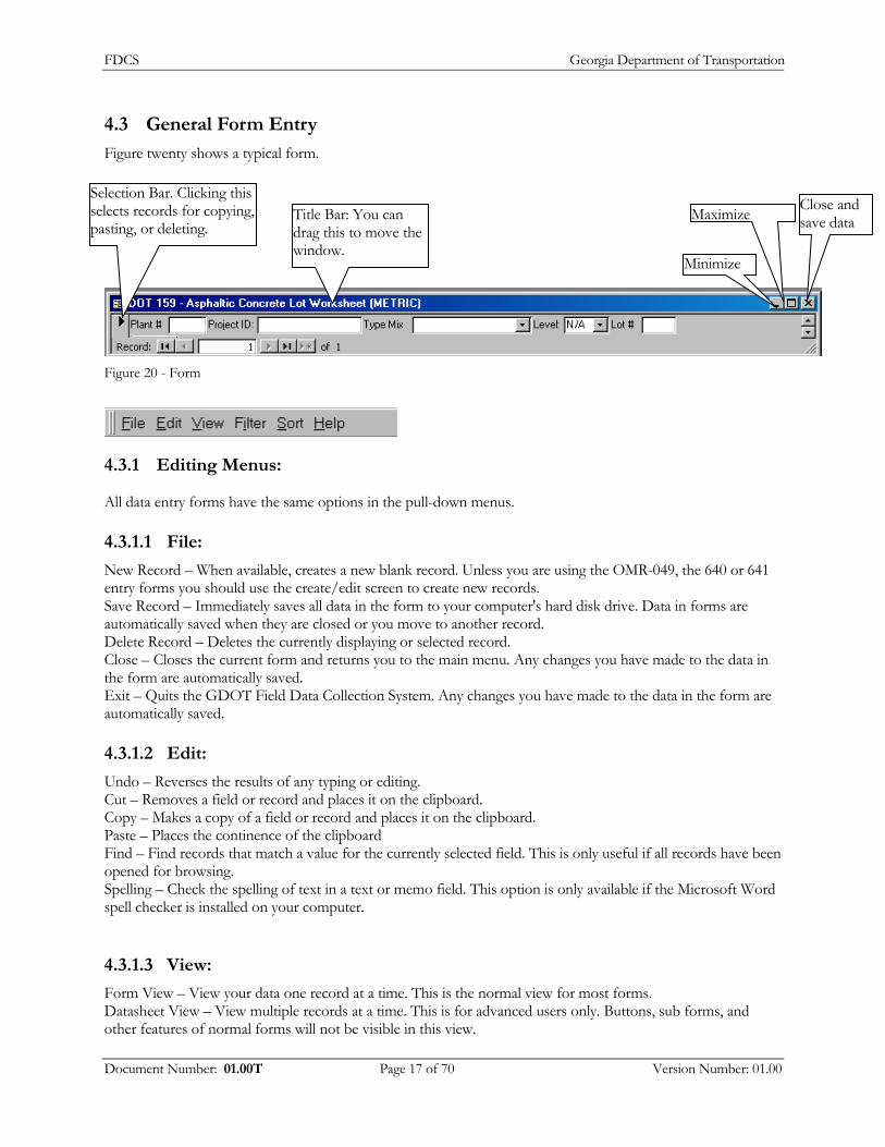
4.3 General Form Entry
Figure twenty shows a typical form.
Selection Bar. Clicking this selects records for copying, pasting, or deleting.
Minimize
Close and save data MaximizeTitle Bar: You can
drag this to move the window.
Figure 20 - Form
4.3.1 Editing Menus:
All data entry forms have the same options in the pull-down menus.
4.3.1.1 File:
New Record – When available, creates a new blank record. Unless you are using the OMR-049, the 640 or 641 entry forms you should use the create/edit screen to create new records. Save Record – Immediately saves all data in the form to your computer's hard disk drive. Data in forms are automatically saved when they are closed or you move to another record. Delete Record – Deletes the currently displaying or selected record. Close – Closes the current form and returns you to the main menu. Any changes you have made to the data in the form are automatically saved. Exit – Quits the GDOT Field Data Collection System. Any changes you have made to the data in the form are automatically saved.
4.3.1.2 Edit:
Undo – Reverses the results of any typing or editing. Cut – Removes a field or record and places it on the clipboard. Copy – Makes a copy of a field or record and places it on the clipboard. Paste – Places the continence of the clipboard Find – Find records that match a value for the currently selected field. This is only useful if all records have been opened for browsing. Spelling – Check the spelling of text in a text or memo field. This option is only available if the Microsoft Word spell checker is installed on your computer.
4.3.1.3 View:
Form View – View your data one record at a time. This is the normal view for most forms. Datasheet View – View multiple records at a time. This is for advanced users only. Buttons, sub forms, and other features of normal forms will not be visible in this view.
Document Number: 01.00T Page 17 of 70 Version Number: 01.00
FDCS Georgia Department of Transportation
4.3.1.4 Filter:
Filter by Selection – Limits the current set of records you are working with to just those that have matching values to the currently selected field. Filter Excluding Selection – Limits the current set of records you are working with to just those that have values that do not match the currently selected field. Remove Filter/Sort – Returns you to working with all records that you have entered. Apply Filter Sort – After removing a Filter or sort this can re-apply the same filter or sort without re-specifying what it is you want to filter or sort by.
4.3.1.5 Sort:
Sort Ascending – Sorts all records you are working with in ascending order by the currently selected field. Sort Descending – Sorts all records you are working with in descending order by the currently selected field.
4.3.1.6 Help:
About...: Displays the name of the program and the current contact information.
Document Number: 01.00T Page 18 of 70 Version Number: 01.00

FDCS Georgia Department of Transportation
4.4 DOT 152 - Water Turbidity Entry Form
Figure 21 - Water Turbidity Form
This form enables easy and accurate entry of DOT 152 Water Turbidity test data. Technician ID Code - The code assigned by the DOT to designated people who are authorized to submit test reports to the DOT Sample Number - This is the arbitrarily assigned number assigned to the sample by the testing technician. This is an integer numeric value. Sample Year - Because the sample numbers restart at the beginning of each year, each sample number must also be accompanied by the year in which the sample was taken. Project Code - This is the project designation for the specific project being performed under the contract. You must type the project code in EXACTLY as it is issued; otherwise your data may not be filed properly. Contract ID - This is the ID of the contract under which this work is being preformed and paid under. The Contract ID’s format is upper case, letter “O”s are not allowed, and dashes in the format: 000000-00-000-0. Contractor No. - This is the ID code of the paving contractor placing the mix District No. - The DOT District Number where the project is located. This is either 1,2,3,4,5,6, or 7. County Number - The DOT county designation code that the work for this contract is being preformed in. Area Engineer - The ID Code for the area engineer who is responsible for the project. Date Sampled -The date the sample was taken. The Date field is a date time object that can contain any date between 1/1/100 and 12/31/9999. Under the Microsoft Windows operating system a date can be displayed and entered in a number of different ways and depends on your country settings in the Windows control panel. Time Sampled - The time at which the sample was taken. Under the Microsoft Windows operating system a time can be displayed and entered in a number of different ways and depends on your country settings in the Windows control panel. Upstream reading NTU - The upstream reading in NTUs Downstream reading NTU - The Downstream reading in NTUs. Station Number - The station number where this test is performed. This is measured in Linear Feet from the start of the project. It is formatted, as 16+30 which means the station is 1630 feet from the start of the project. If the location of the test is not at a station, then specify in the remarks. Silt Fence, Sediment Basin, Silt Gates, and Grassing - A rating of each of these items at the test site, which may be Poor, Fair, Satisfactory, Good, or Excellent. Remarks - Any additional remarks may be entered here.
Document Number: 01.00T Page 19 of 70 Version Number: 01.00

FDCS Georgia Department of Transportation
4.5 DOT 159 - Asphaltic Concrete Lot Worksheet
Figure 22 - Asphaltic Concrete Lot Worksheet
This form enables easy and accurate entry of DOT 159 Asphaltic Concrete Lot Worksheet data. Because of the large number of fields on this form, the form in broken up in to multiple pages which can be selected by clicking on the appropriate tab. The fields that uniquely identify your 159 Asphaltic Concrete Lot Worksheet record are Asphalt Plant Number, Project ID Code, Type Mix, Level, and Lot Number. Each record may have more than one sample on the sample page. List of entry fields on this form:
4.5.1 Header Tab
Asphalt Plant Number - An Asphalt Plant Number is the designation assigned by the DOT to asphalt producers that supply material to the DOT. The Source Plant Number entered must be the number of the plant producing the mix. This is a numeric field. Only numbers may be entered. Project ID Code - This is the project designation for the specific project being performed under the contract. You must type the project code in EXACTLY as it is issued; otherwise your data may not be filed properly. Type Mix - The GDOT Mix designation for the mix being tested. This must be a valid mix code selected from the dropdown list. Level - The level of the mix if applicable. Either N/A, A, B, C or D. Lot No - The lot number of the mix being tested. Only positive integer numeric values are valid in this field. Letters and symbols are not allowed. Zero padding is not allowed. Contract ID - This is the ID of the contract under which this work is being preformed and paid under. The Contract ID’s format is upper case, letter “O”s are not allowed, and dashes in the format: 000000-00-000-0. Date - The date of production for this lot. Tech ID – The Tech ID number. Mix ID - The mix I.D number from the Job Mix Formula. Contractor ID - The code number of the paving contractor placing the mix. County Number - The DOT county designation code that the work for this contract is being preformed in.
Document Number: 01.00T Page 20 of 70 Version Number: 01.00

FDCS Georgia Department of Transportation
District Number - The DOT District Number where the project is located. This is either 1,2,3,4,5,6, or 7. Corrected Copy - Check this box if this is a corrected copy. Blend - The blend of the mix, you may select RAP, Virgin, PM RAP, PM Virgin, Gilsonite, or you may enter a different blend. Type Course - The designation code for the course being placed (B)ase, (I)ntermediate, (S)urface, (L)evel, (P)atch AC Grade - The AC Grade number from the Job Mix Formula (AC20, AC20S, AC20, etc) AC Source number - The code number for the Asphalt Cement Supplier. Daily Tonage (Max 10 Days)- the amount of sample.
4.5.2
4.5.3
Tests Tab
DOT Technician Code - The code assigned by the DOT to designated people who are authorized to submit test reports to the DOT. Hydrated Lime - Check this box if the Mix contains hydrated lime. Liquid Antistrip Added - Check this box if the mix contains liquid antistrip additive as an ingredient. Quantity this lot - The total tons produced in this lot. The English form requires you to enter this value in tons, and the metric form requires you to enter this value in megagrams. If you do not use the specified unit of measure your data will be wrong. Use Void Test Specification – Check this box if the Void Test Specification is being use to perform this test rather than the compaction specification. Control Strip Density - Tests 1-5: The control strip density. The English form requires you to enter this value in lbs/ft³ and the metric form requires you to enter this value in kg/m³. If you do not use the specified unit of measure your data will be wrong. Target Density - The target density (the average of the control strip density) The English form requires you to enter this value in lbs/ft³ and the metric form requires you to enter this value in kg/m³. If you do not use the specified unit of measure your data will be wrong. Theoretical Density - The theoretical density specified from the Job Mix Formula. The English form requires you to enter this value in lbs/ft³ and the metric form requires you to enter this value in kg/m³. If you do not use the specified unit of measure your data will be wrong. Max % Air Voids – The Maximum allowed air voids from the spec – 7.8 for end result or 8.3 for a non-end result. This value is specified only when using the voids testing spec. Max Practical % Air Voids – The Maximum practical allowed air voids if the spec can not be met. In Place Density - Test 1-5 the individual density measured at the compaction test sites. The English form requires you to enter this value in lbs/ft³ and the metric form requires you to enter this value in kg/m³. If you do not use the specified unit of measure your data will be wrong. IPD ReEval – Tests 1-5 the in place density measured from a re-evaluation test. Strip Test Time - Test 1-5. The time the strip test was performed. Strip Test % Retained - Test 1-5 the percent of the material that is not stripped from the strip test (boil test). Strip Test % Lime Check - Test 1-5 The percent of hydrated lime in the mix. Percent JMF (for 1 1/2in, 1 in, 1/2in, 3/8 in, No. 4, No. 8, No. 50, No. 200) sieves - The required percent passing from the Job Mix Formula. Percent JMF AC – The percent of asphalt Cement from the Job Mix Formula.
Samples
Sample ID – An ID code consisting of your Technician code, a dash, and the sample number assigned to the sample. SampleDate – The date on which the sample was taken. Load Number – Number of the truckload this sample was taken from. Sample Time – The time at which this sample was taken.
Document Number: 01.00T Page 21 of 70 Version Number: 01.00

FDCS Georgia Department of Transportation
Temperature – The temperature of the mix when the sample is taken. The English form requires you to enter this value in Fahrenheit and the metric form requires you to enter this value in Celsius. If you do not use the specified unit of measure your data will be wrong. Total Mass (g) – The total mass of the sample in grams. Beginning Mass (g) – The dry mass, in grams, of the silica and the filter paper. Final Mass (g) – the constant dry mass, in grams, of the silica, the filter and the -200 material Aggregate Dry Mass (g) - The aggregate dry mass of the sample in grams Mass: (for 1 1/2in, 1 in, 1/2in, 3/8 in, No. 4, No. 8, No. 50, No. 200) sieves - The accumulated mass, in grams, retained on the sieve. GDT125 method - Check this box if this sample uses the GDT152 Ignition Oven test rather than the extraction method. Percent Pass AC - The amount of AC in grams IA sample - Check this box is there was an IA comparison against this sample.
4.5.4 Pay Factors
End Results: Checked for End Result Project or not checked for Non-End result project (pay factors) Compaction - The pay factor for Compaction. Avg. Comp. - The pay factor for average percent compaction. Range - The pay factor for range. Extraction - The pay factor for Extraction. Sieve - The pay factor for sieve. A.C - The pay factor for asphalt cement. Applicable Pay Factor - The applicable pay factor. Remarks - Any additional information.
Document Number: 01.00T Page 22 of 70 Version Number: 01.00
FDCS Georgia Department of Transportation
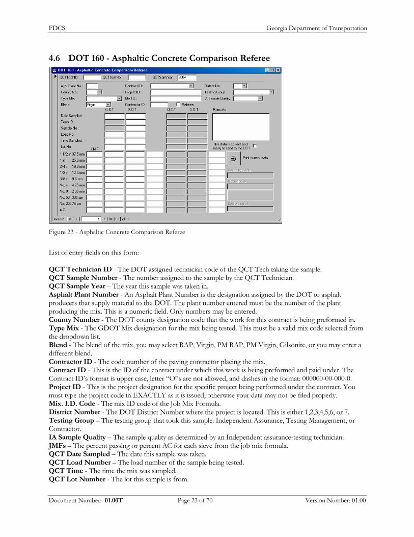
4.6 DOT 160 - Asphaltic Concrete Comparison Referee
Figure 23 - Asphaltic Concrete Comparison Referee
List of entry fields on this form: QCT Technician ID - The DOT assigned technician code of the QCT Tech taking the sample. QCT Sample Number - The number assigned to the sample by the QCT Technician. QCT Sample Year – The year this sample was taken in. Asphalt Plant Number - An Asphalt Plant Number is the designation assigned by the DOT to asphalt producers that supply material to the DOT. The plant number entered must be the number of the plant producing the mix. This is a numeric field. Only numbers may be entered. County Number - The DOT county designation code that the work for this contract is being preformed in. Type Mix - The GDOT Mix designation for the mix being tested. This must be a valid mix code selected from the dropdown list. Blend - The blend of the mix, you may select RAP, Virgin, PM RAP, PM Virgin, Gilsonite, or you may enter a different blend. Contractor ID - The code number of the paving contractor placing the mix. Contract ID - This is the ID of the contract under which this work is being preformed and paid under. The Contract ID’s format is upper case, letter “O”s are not allowed, and dashes in the format: 000000-00-000-0. Project ID - This is the project designation for the specific project being performed under the contract. You must type the project code in EXACTLY as it is issued; otherwise your data may not be filed properly. Mix. I.D. Code - The mix ID code of the Job Mix Formula. District Number - The DOT District Number where the project is located. This is either 1,2,3,4,5,6, or 7. Testing Group – The testing group that took this sample: Independent Assurance, Testing Management, or Contractor. IA Sample Quality – The sample quality as determined by an Independent assurance-testing technician. JMFs – The percent passing or percent AC for each sieve from the job mix formula. QCT Date Sampled – The date this sample was taken. QCT Load Number – The load number of the sample being tested. QCT Time - The time the mix was sampled. QCT Lot Number - The lot this sample is from.
Document Number: 01.00T Page 23 of 70 Version Number: 01.00

FDCS Georgia Department of Transportation
QCT Percent Passing and Percent AC - The percent passing each sieve from the QCT’s test. DOT Sample Date - The date this sample was taken. DOT Technician ID - The DOT Technician ID of the DOT technician taking this sample. DOT Sample Number - The technician ID number and the sample number of this sample. DOT Load Number - The load number of the sample being tested. DOT Time - The time the mix was sampled. DOT Lot Number - The lot this sample is from. DOT Percent Passing or AC - The percent passing the sieve or percent AC. Referee – Check this box if there is a referee sample. Referee QCT Date Sampled – Check this box if there is a referee sample. Referee QCT Technician ID - The DOT Technician ID of the QCT technician taking this sample. Referee QCT Sample Number - The number assigned to this sample by the testing technician. Referee QCT Load Number – The DOT assigned technician code of the QCT Tech taking the sample. Referee QCT Time - The time the mix was sampled. Referee QCT Lot Number - The lot this sample is from. Referee QCT Percent Passing and Percent AC - The percent passing each sieve from the QCT’s test. Referee DOT Sample Date - The date this sample was taken. Referee DOT Technician ID - The DOT Technician ID of the DOT technician taking this sample. Referee DOT Sample Number - The number assigned to this sample by the testing technician. Referee DOT Load Number - The load number of the sample being tested. Referee DOT Time - The time the mix was sampled. Referee DOT Lot Number - The lot this sample is from. Referee DOT Percent Passing or AC - The percent passing the sieves or percent AC. Remarks - Any additional information you want to record.
Document Number: 01.00T Page 24 of 70 Version Number: 01.00

FDCS Georgia Department of Transportation
4.7 DOT 161 - Asphaltic Concrete Quality Assurance
Figure 24 - Asphaltic Concrete Quality Assurance
The fields that uniquely identify DOT161s are the Technician ID, the Sample Number, and the Sample Year. List of entry fields on this form: Technician ID - The DOT assigned technician code of the person taking this sample. Sample Number – The number assigned to the sample by the testing technician. Sample Year – The year that the sample was taken in. Asphalt Plant number – An Asphalt Plant Number is the designation assigned by the DOT to asphalt producers that supply material to the DOT. The plant number entered must be the number of the plant producing the mix. This is a numeric field. Only numbers may be entered. Contract ID - This is the ID of the contract under which this work is being preformed and paid under. The Contract ID’s format is upper case, letter “O”s are not allowed, and dashes in the format: 000000-00-000-0. District Number - The DOT District Number where the project is located. This is either 1,2,3,4,5,6, or 7. County Number- The DOT county designation code that the work for this contract is being preformed in. Type Mix- The GDOT Mix designation for the mix being tested. This must be a valid mix code selected from the dropdown list. Blend - The blend of the mix, you may select RAP, Virgin, PM RAP, PM Virgin, Gilsonite, or you may enter a different blend. Contractor Code- The code number of the paving contractor placing the mix Project ID - This is the project designation for the specific project being performed under the contract. You must type the project code in EXACTLY as it is issued; otherwise your data may not be filed properly. Mix. I.D. Code - The mix ID code of the Job Mix Formula. Load Number- The load number of the sample being tested. Date Sampled - The date the mix was sampled.
Document Number: 01.00T Page 25 of 70 Version Number: 01.00
FDCS Georgia Department of Transportation
Time Sampled - The time the mix was sampled. Temperature - The temperatire, in Feranheight (around 300) or Celsius (around 150) , of the mix. JMFS – The Percent passings and the percent AC specified on the job mix formula. QA Percent Passing and AC - The percent passing the sieve or percent AC Remarks - Any additional information you want to record.
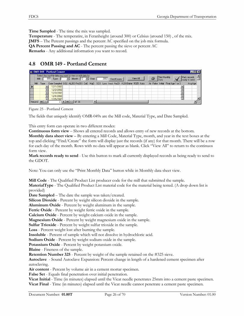
4.8 OMR 149 - Portland Cement
Figure 25 - Portland Cement
The fields that uniquely identify OMR-049s are the Mill code, Material Type, and Date Sampled. This entry form can operate in two different modes: Continuous form view – Shows all entered records and allows entry of new records at the bottom. Monthly data sheet view – By entering a Mill Code, Material Type, month, and year in the text boxes at the top and clicking “Find/Create” the form will display just the records (if any) for that month. There will be a row for each day of the month. Rows with no data will appear as blank. Click “View All” to return to the continuos form view. Mark records ready to send - Use this button to mark all currently displayed records as being ready to send to the GDOT. Note: You can only use the “Print Monthly Data” button while in Monthly data sheet view. Mill Code - The Qualified Product List producer code for the mill that submitted the sample. MaterialType - The Qualified Product List material code for the material being tested. (A drop down list is provided) Date Sampled – The date the sample was taken/created. Silicon Dioxide - Percent by weight silicon dioxide in the sample. Aluminum Oxide - Percent by weight aluminum in the sample. Ferric Oxide - Percent by weight ferric oxide in the sample. Calcium Oxide - Percent by weight calcium oxide in the sample. Magnesium Oxide - Percent by weight magnesium oxide in the sample. Sulfur Trioxide - Percent by weight sulfur trioxide in the sample. Loss - Percent weight lost after burning the sample. Insoluble - Percent of sample which will not dissolve in hydrochloric acid. Sodium Oxide - Percent by weight sodium oxide in the sample. Potassium Oxide - Percent by weight potassium oxide. Blaine - Fineness of the sample. Retention Number 325 - Percent by weight of the sample retained on the #325 sieve. Autoclave - Sound Autoclave Expansion: Percent change in length of a hardened cement specimen after autoclaving. Air content - Percent by volume air in a cement mortar specimen. False Set - Equals final penetration over initial penetration. Vicat Initial - Time (in minutes) elapsed until the Vicat needle penetrates 25mm into a cement paste specimen. Vicat Final - Time (in minutes) elapsed until the Vicat needle cannot penetrate a cement paste specimen.
Document Number: 01.00T Page 26 of 70 Version Number: 01.00
FDCS Georgia Department of Transportation
Age 1 or 3 - Age of compressive strength specimen in days. Average for 1 or 3 - Average for 1 or 3 days. Age 3 or 7 - Age of compressive strength specimen. Average for 3 or 7 - Average for 3 or 7 days. Split Sample (SS) - Check this box if this is a Split Sample. Meets Requirements - Select passed or failed based on the results. Remarks - Remarks made by the supplier.
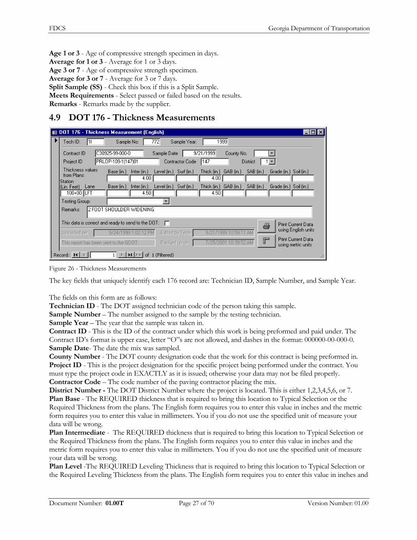
4.9 DOT 176 - Thickness Measurements
Figure 26 - Thickness Measurements
The key fields that uniquely identify each 176 record are: Technician ID, Sample Number, and Sample Year. The fields on this form are as follows: Technician ID - The DOT assigned technician code of the person taking this sample. Sample Number – The number assigned to the sample by the testing technician. Sample Year – The year that the sample was taken in. Contract ID - This is the ID of the contract under which this work is being preformed and paid under. The Contract ID’s format is upper case, letter “O”s are not allowed, and dashes in the format: 000000-00-000-0. Sample Date- The date the mix was sampled. County Number - The DOT county designation code that the work for this contract is being preformed in. Project ID - This is the project designation for the specific project being performed under the contract. You must type the project code in EXACTLY as it is issued; otherwise your data may not be filed properly. Contractor Code – The code number of the paving contractor placing the mix. District Number - The DOT District Number where the project is located. This is either 1,2,3,4,5,6, or 7. Plan Base - The REQUIRED thickness that is required to bring this location to Typical Selection or the Required Thickness from the plans. The English form requires you to enter this value in inches and the metric form requires you to enter this value in millimeters. You if you do not use the specified unit of measure your data will be wrong. Plan Intermediate - The REQUIRED thickness that is required to bring this location to Typical Selection or the Required Thickness from the plans. The English form requires you to enter this value in inches and the metric form requires you to enter this value in millimeters. You if you do not use the specified unit of measure your data will be wrong. Plan Level -The REQUIRED Leveling Thickness that is required to bring this location to Typical Selection or the Required Leveling Thickness from the plans. The English form requires you to enter this value in inches and
Document Number: 01.00T Page 27 of 70 Version Number: 01.00

FDCS Georgia Department of Transportation
the metric form requires you to enter this value in millimeters. You if you do not use the specified unit of measure your data will be wrong. Plan Surf - The REQUIRED thickness that is required to bring this location to Typical Selection or the Required Thickness from the plans. The English form requires you to enter this value in inches and the metric form requires you to enter this value in millimeters. You if you do not use the specified unit of measure your data will be wrong. Plan Thickness - Total REQUIRED thickness. The English form requires you to enter this value in inches and the metric form requires you to enter this value in millimeters. You if you do not use the specified unit of measure your data will be wrong. Plan GAB - The REQUIRED thickness that is required to bring this location to Typical Selection or the Required Thickness from the plans. The English form requires you to enter this value in inches and the metric form requires you to enter this value in millimeters. You if you do not use the specified unit of measure your data will be wrong. Plan SAB - The REQUIRED thickness that is required to bring this location to Typical Selection or the Required Thickness from the plans. The English form requires you to enter this value in inches and the metric form requires you to enter this value in millimeters. You if you do not use the specified unit of measure your data will be wrong. Plan Grade - The REQUIRED thickness that is required to bring this location to Typical Selection or the Required Thickness from the plans. The English form requires you to enter this value in inches and the metric form requires you to enter this value in millimeters. You if you do not use the specified unit of measure your data will be wrong. Plan Soil - The REQUIRED thickness that is required to bring this location to Typical Selection or the Required Thickness from the plans. The English form requires you to enter this value in inches and the metric form requires you to enter this value in millimeters. You if you do not use the specified unit of measure your data will be wrong. Station Number - The station number where this test is performed. This is measured in Linear Feet from the start of the project in English, and Linear Meters in metric. In English it is formatted, as 16+30 which means the station is 1630 feet from the start of the project. In metric it is formatted 4+360 which means the station is 4360 meters from the start of the project. Lane – The lane the measurement was taken, example SBL Base - The base measurement of the core. The English form requires you to enter this value in inches and the metric form requires you to enter this value in millimeters. You if you do not use the specified unit of measure your data will be wrong. Intermediate - The intermediate measurement of the core. The English form requires you to enter this value in inches and the metric form requires you to enter this value in millimeters. If you do not use the specified unit of measure your data will be wrong. Level - The level measurement of the core. The English form requires you to enter this value in inches and the metric form requires you to enter this value in millimeters. If you do not use the specified unit of measure your data will be wrong. Surf - The surf measurement of the core. The English form requires you to enter this value in inches and the metric form requires you to enter this value in millimeters. If you do not use the specified unit of measure your data will be wrong. Thickness - Total thickness. The English form requires you to enter this value in inches and the metric form requires you to enter this value in millimeters. If you do not use the specified unit of measure your data will be wrong. GAB - The total measurement of the final lift. The English form requires you to enter this value in inches and the metric form requires you to enter this value in millimeters. If you do not use the specified unit of measure your data will be wrong. SAB - The total measurement of the final lift. The English form requires you to enter this value in inches and the metric form requires you to enter this value in millimeters. If you do not use the specified unit of measure your data will be wrong.
Document Number: 01.00T Page 28 of 70 Version Number: 01.00
FDCS Georgia Department of Transportation
Grade - The total thickness of the final lift. The English form requires you to enter this value in inches and the metric form requires you to enter this value in millimeters. If you do not use the specified unit of measure your data will be wrong. Soil - The total thickness of the final lift. The English form requires you to enter this value in inches and the metric form requires you to enter this value in millimeters. If you do not use the specified unit of measure your data will be wrong. Testing Group - Comparison sample by independent assurance. Remarks - Any additional information that is needed for this record.
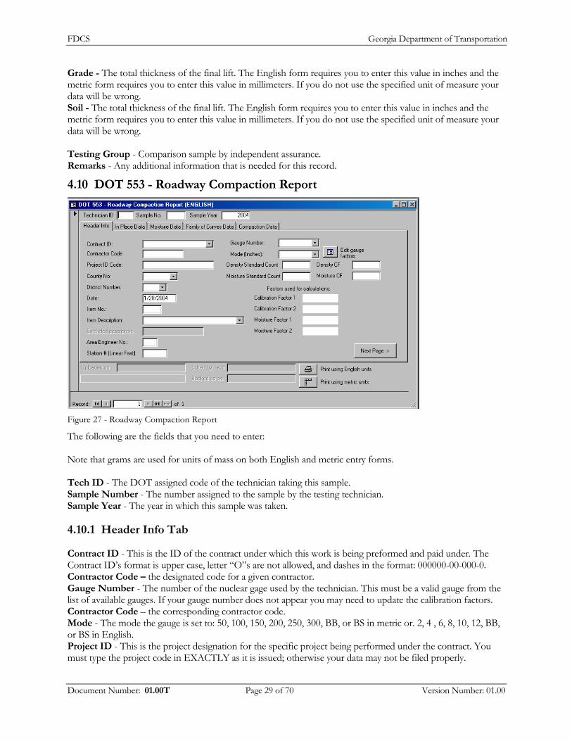
4.10 DOT 553 - Roadway Compaction Report
Figure 27 - Roadway Compaction Report
The following are the fields that you need to enter: Note that grams are used for units of mass on both English and metric entry forms. Tech ID - The DOT assigned code of the technician taking this sample. Sample Number - The number assigned to the sample by the testing technician. Sample Year - The year in which this sample was taken.
4.10.1 Header Info Tab
Contract ID - This is the ID of the contract under which this work is being preformed and paid under. The Contract ID’s format is upper case, letter “O”s are not allowed, and dashes in the format: 000000-00-000-0. Contractor Code – the designated code for a given contractor. Gauge Number - The number of the nuclear gage used by the technician. This must be a valid gauge from the list of available gauges. If your gauge number does not appear you may need to update the calibration factors. Contractor Code – the corresponding contractor code. Mode - The mode the gauge is set to: 50, 100, 150, 200, 250, 300, BB, or BS in metric or. 2, 4 , 6, 8, 10, 12, BB, or BS in English. Project ID - This is the project designation for the specific project being performed under the contract. You must type the project code in EXACTLY as it is issued; otherwise your data may not be filed properly.
Document Number: 01.00T Page 29 of 70 Version Number: 01.00
FDCS Georgia Department of Transportation
Density Standard Count - The Density standard count. Density CF – The density standard count correction factor. County Number - The DOT county designation code that the work for this contract is being preformed in. District Number - The DOT District Number where the project is located. This is either 1,2,3,4,5,6, or 7. Moisture Standard Count - The Moisture standard count. Moisture CD - The Moisture standard count correction factor. Date - The date this sample was taken. Item Number - The item number for the material the compaction is being run on. Item Description - The type of material being tested. Select a valid type from the drop down list. Extended Description - Extended description of item if "other” is selected for item description. Area Engineer Number - The area engineer in charge of the project. Station Number - The station number where this test is performed. This is measured in Linear Feet from the start of the project in English, and Linear Meters in metric. In English it is formatted, as 16+30 which means the station is 1630 feet from the start of the project. In metric it is formatted 4+360 which means the station is 4360 meters from the start of the project.
4.10.2
4.10.3
4.10.4
Moisture Data
Wet Mass – The total mass in grams. Dry Mass – The final dry mass in grams.
Family of Curves Data tab:
Wet Mass - Total mass in grams. Dried Mass - Final dry mass in grams. Mass of Mixture plus Mold - The mass of the mixture plus the weight of the mold in grams. Mass of Mold - The mass of the mold in grams. Mold Correction Factor - Mold Correction Factor in lb/ft³/g in English or kg/m³/g in metric. Chart - The Family of Curves chart to use - A, B, C or L for Laboratory values. Max Dry Density - Max. Dry Den./Fr. Curve. The English form requires you to enter this value in lbs/ft³ and the metric form requires you to enter this value in kg/m³. If you do not use the specified unit of measure your data will be wrong. Optimum Percent Moisture – Optimum Percent Moisture. The fields you can enter represent the “final proctor”. If a new set of measurements from another proctor is needed, then click “New Proctor”. The old data will be moved in to the “Previous Proctors” section and you may enter the new set of measurements in the “final proctor” section.
Compaction Data
Maximum Dry Density – The calculated Maximum dry density. this value is overrideable. The English form requires you to enter this value in lbs/ft³ and the metric form requires you to enter this value in kg/m³. If you do not use the specified unit of measure your data will be wrong. Optimum Percent Moisture – Optimum Percent Moisture. Percent Compaction Required - Percent compaction required for this test. Recheck - Check this box if this sample is a recheck. Testing Group - Select the testing group that took this sample. IA Quality – The Sample Quality as reported by IA techs. Remarks – Any additional remarks.
Document Number: 01.00T Page 30 of 70 Version Number: 01.00
FDCS Georgia Department of Transportation
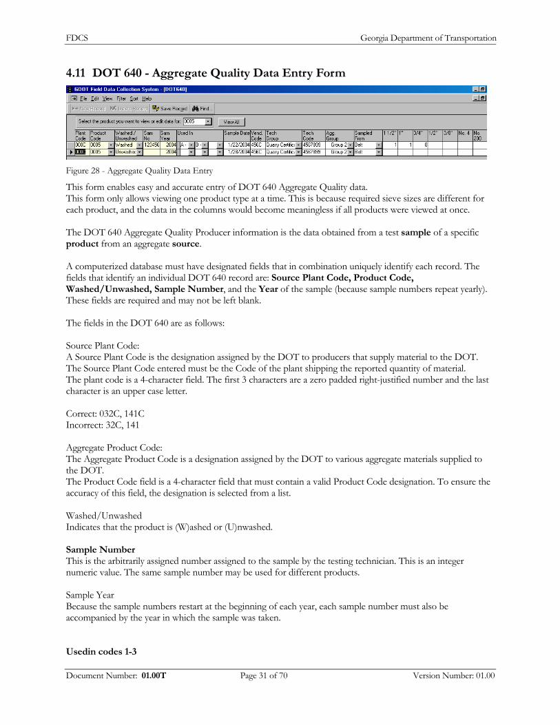
4.11 DOT 640 - Aggregate Quality Data Entry Form
Figure 28 - Aggregate Quality Data Entry
This form enables easy and accurate entry of DOT 640 Aggregate Quality data. This form only allows viewing one product type at a time. This is because required sieve sizes are different for each product, and the data in the columns would become meaningless if all products were viewed at once. The DOT 640 Aggregate Quality Producer information is the data obtained from a test sample of a specific product from an aggregate source. A computerized database must have designated fields that in combination uniquely identify each record. The fields that identify an individual DOT 640 record are: Source Plant Code, Product Code, Washed/Unwashed, Sample Number, and the Year of the sample (because sample numbers repeat yearly). These fields are required and may not be left blank. The fields in the DOT 640 are as follows: Source Plant Code: A Source Plant Code is the designation assigned by the DOT to producers that supply material to the DOT. The Source Plant Code entered must be the Code of the plant shipping the reported quantity of material. The plant code is a 4-character field. The first 3 characters are a zero padded right-justified number and the last character is an upper case letter. Correct: 032C, 141C Incorrect: 32C, 141 Aggregate Product Code: The Aggregate Product Code is a designation assigned by the DOT to various aggregate materials supplied to the DOT. The Product Code field is a 4-character field that must contain a valid Product Code designation. To ensure the accuracy of this field, the designation is selected from a list. Washed/Unwashed Indicates that the product is (W)ashed or (U)nwashed. Sample Number This is the arbitrarily assigned number assigned to the sample by the testing technician. This is an integer numeric value. The same sample number may be used for different products. Sample Year Because the sample numbers restart at the beginning of each year, each sample number must also be accompanied by the year in which the sample was taken. Usedin codes 1-3
Document Number: 01.00T Page 31 of 70 Version Number: 01.00

FDCS Georgia Department of Transportation
These fields specify up to three different ways in which the material will be used. These are each single character fields that may contain “A” through “Y”. A list of DOT used in-codes are provided in a drop-down box. Values may be left blank if there are less than 3 uses. Sample Date This is the date on which the sample was tested. The Date field is a date time object that can contain any date between 1/1/100 and 12/31/9999. Under the Microsoft Windows operating system a date can be entered and displayed in a number of different ways depending on the country settings in the Windows control panel. Vendor Code: This is the DOT assigned Vendor designation of a company that is to resell the material. This value is only supplied if the material is being re-sold instead of being delivered to a project. This is a 4-character code from QPL2, and is NOT the sitemanager code. If there is no vendor then leave this field blank. Technician Group Specifies the group the technician taking this sample belongs to. These samples may be taken by either Quarry Certification (Technicians employed by the aggregate plant) or Independent assurance (technicians employed by the DOT). DOT Technician Code The code assigned by the DOT to designated people who are authorized to submit test reports to the DOT Aggregate Group Specifies if the material falls in to aggregate group 1 (limestone) or aggregate group 2 (granite) Sampled From A generalized location from which the sample was taken. This is either (S)tockpile, (B)elt, (R)oadway, rail (C)ar, (T)ruck, or (O)ther. Percent Passing 1-10 The percent of material passing each of the required sieves (ten max). The sieve sizes required for testing are pulled from a pre-programmed list and are displayed on the column heading on the entry form. Decimal values may be specified. Each percent passing value obtained from the test is required to be less than the previous value A larger value would represent a physical impossibility. Sand Equivalency If applicable, the numeric results obtained from a GDT-63 sand equivalency test. Meets Requirements Indicates if the sample is passing or failing based on the results. Remarks The remark field is a memo field where users can enter any additional relevant data they want. Send Checking this box indicates that you have accurately and honestly entered your data and that it is ready to send to the GDOT. The label next to this box indicates if this record has been sent (Or more accurately, extracted for sending).
Document Number: 01.00T Page 32 of 70 Version Number: 01.00

FDCS Georgia Department of Transportation
4.12 DOT 641 - Aggregate Quantity Form
Figure 29 - Aggregate Quantity Form
This form enables easy and accurate entry of DOT 641 Aggregate Quantity data. The DOT 641 Aggregate Quantity Producer Report is a report of the quantity of material supplied by a source plant on a specific day, separately reporting the quantities of each product for each use for each project. The fields that uniquely identify a DOT 641 report are the Plant Code, Date Sampled, Project Code, Product Code, Washed/Unwashed and Used In. The fields in the DOT 640 are as follows: Source Plant Code: A Source Plant Code is the designation assigned by the DOT to producers that supply material to the DOT. The Source Plant Code entered must be the Code of the plant shipping the reported quantity of material. This plant code is a 4-character field. The first 3 characters are a zero padded right-justified number and the last character is an upper case letter. Correct: 032C, 141C Incorrect: 32C, 141 Date Sampled: The date is the single date on which the quantity of material was supplied. The Date field is a date time object that can contain any date between 1/1/100 and 12/31/9999. Under the Microsoft Windows operating system a date can be displayed and entered in a number of different ways and depends on the country settings in the Windows control panel. Project Code: This is the project designation for the specific project being performed under the contract. You must type the project code in EXACTLY as it is issued; otherwise your data may not be filed properly. Aggregate Product Code: The Aggregate Product Code is a designation assigned by the DOT to various aggregate materials supplied to the DOT. The Product Code field is a 4-character field that must contain a valid Product Code designation. To ensure the accuracy of this field, the designation is selected from a list. Washed/Unwashed: Indicates that the product is (W)ashed or (U)nwashed. Used In: The Used In code specifies what the material is going to be used for. The code is from a list of DOT Used In codes. The Used In code field is a single upper case letter from A to Z. Each letter represents a different way in which the material can be used.
Document Number: 01.00T Page 33 of 70 Version Number: 01.00
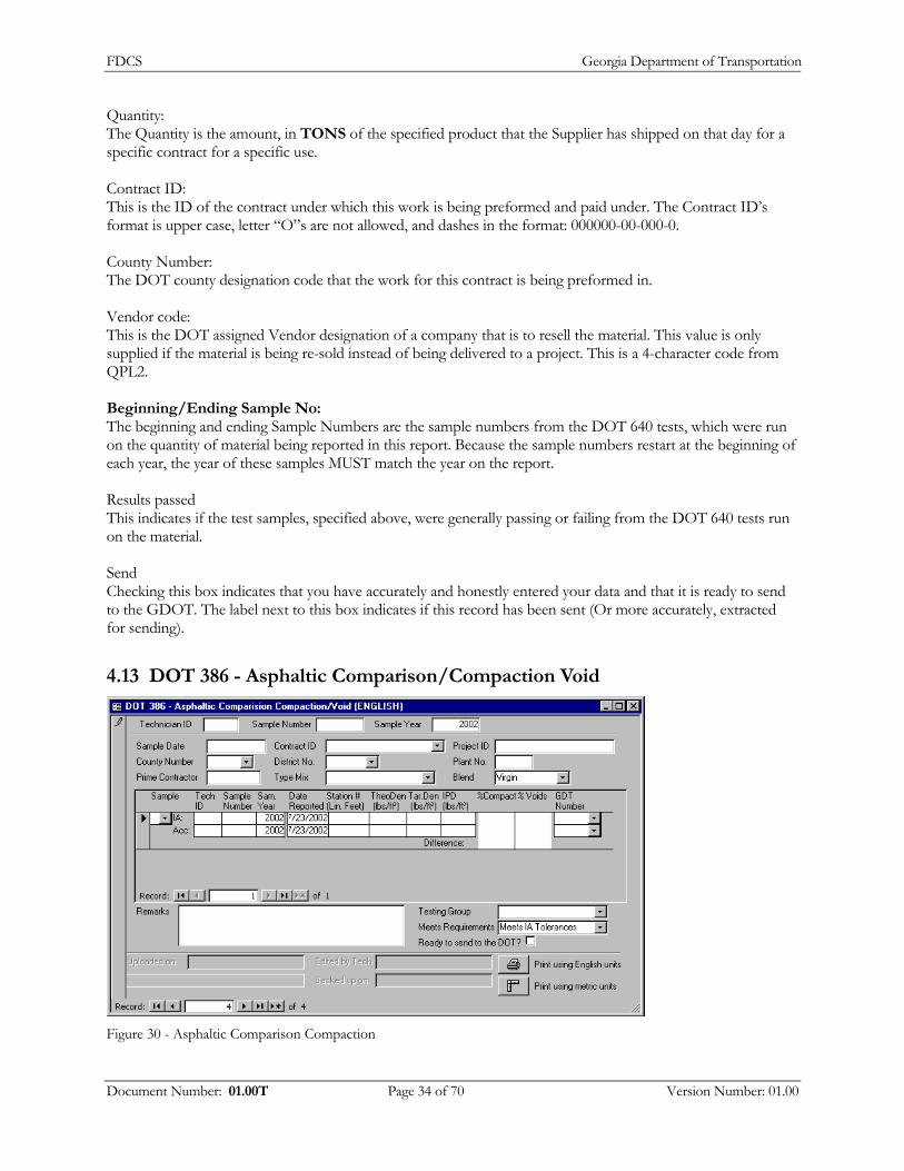
FDCS Georgia Department of Transportation
Quantity: The Quantity is the amount, in TONS of the specified product that the Supplier has shipped on that day for a specific contract for a specific use. Contract ID: This is the ID of the contract under which this work is being preformed and paid under. The Contract ID’s format is upper case, letter “O”s are not allowed, and dashes in the format: 000000-00-000-0. County Number: The DOT county designation code that the work for this contract is being preformed in. Vendor code: This is the DOT assigned Vendor designation of a company that is to resell the material. This value is only supplied if the material is being re-sold instead of being delivered to a project. This is a 4-character code from QPL2. Beginning/Ending Sample No: The beginning and ending Sample Numbers are the sample numbers from the DOT 640 tests, which were run on the quantity of material being reported in this report. Because the sample numbers restart at the beginning of each year, the year of these samples MUST match the year on the report. Results passed This indicates if the test samples, specified above, were generally passing or failing from the DOT 640 tests run on the material. Send Checking this box indicates that you have accurately and honestly entered your data and that it is ready to send to the GDOT. The label next to this box indicates if this record has been sent (Or more accurately, extracted for sending).
4.13 DOT 386 - Asphaltic Comparison/Compaction Void
Figure 30 - Asphaltic Comparison Compaction
Document Number: 01.00T Page 34 of 70 Version Number: 01.00
FDCS Georgia Department of Transportation
The DOT 386 is a comparison of the compaction tests run by IA (a test to determine the density of roadway material to help determine the quality of the roadway) with the acceptance test run by the TM. This comparison is done to determine if the differences in the tests meet or exceed set tolerances – The testing technician makes the final determination. The comparison test is assigned the sample number of the first sample taken, but may contain more samples taken immediately after the first sample. Usually there are 5 samples. List of entry fields on this form: Technician ID - The DOT assigned technician code of the person taking this sample. Sample Number – The number assigned to the sample by the testing technician. Sample Year – The year that the sample was taken in. Contract ID - This is the ID of the contract under which this work is being preformed and paid under. The Contract ID’s format is upper case, letter “O”s are not allowed, and dashes in the format: 000000-00-000-0. Project ID - This is the project designation for the specific project being performed under the contract. You must type the project code in EXACTLY as it is issued; otherwise your data may not be filed properly. County Number- The DOT county designation code that the work for this contract is being preformed in. District Number- The DOT District Number where the project is located. This is either 1,2,3,4,5,6, or 7. Plant Number - The numeric designation of the asphalt plant producing the mix. Prime Contractor Code: The 6-digit ID code of the paving contractor placing the mix. Type Mix- The GDOT Mix designation for the mix being tested. This must be a valid mix code selected from the dropdown list. Blend - The blend of the mix, you may select RAP, Virgin, PM RAP, PM Virgin, Gilsonite, or you may enter a different blend. Each DOT 386 comparison test may have one or more comparison samples Independence Assurance Samples IA Technician ID - The DOT assigned IA technician code of the person taking this sample. IA Sample Number – The number assigned to the sample by the testing technician. IA Sample Year – The year that the sample was taken in. IA Sample Date – The date that the IA sample was taken in Station Number - The station number where this test is performed. This is measured in Linear Feet from the start of the project in English, and Linear Meters in metric. In English it is formatted, as 16+30 which means the station is 1630 feet from the start of the project. In metric it is formatted 4+360 which means the station is 4360 meters from the start of the project. IA Theoretical Density – The voidless density of the mix. The English form requires you to enter this value in lbs/ft³ and the metric form requires you to enter this value in kg/m³. If you do not use the specified unit of measure your data will be wrong. IA Target Density – The specified density requirement. . The English form requires you to enter this value in lbs/ft³ and the metric form requires you to enter this value in kg/m³. If you do not use the specified unit of measure your data will be wrong. In Place Density – The measured density of the material tested. The English form requires you to enter this value in lbs/ft³ and the metric form requires you to enter this value in kg/m³. If you do not use the specified unit of measure your data will be wrong. IA Percent Compaction – (CALCULATED) In place Density/ Target Density *100 (In percent) IA Percent Voids – (CALCULATED) = abs(((Inplace density / theoretical density)-1)*100 ) The percentage of the voids (non solid mix or air) in the in place mix. IA GDT Number – Test specification number from sampling and testing manual. Either GDT59 or GDT39.
Document Number: 01.00T Page 35 of 70 Version Number: 01.00

FDCS Georgia Department of Transportation
Acceptance testing sample ACC Technician ID - The DOT assigned Acceptance Testing technician code of the person taking this sample. ACC Sample Number - The number assigned to the sample by the testing technician. ACC Sample Year - The year that the sample was taken in. ACC Sample Date - The date that the IA sample was taken in ACC Station Number - The station number where this test is performed. This is measured in Linear Feet from the start of the project in English, and Linear Meters in metric. In English it is formatted, as 16+30 which means the station is 1630 feet from the start of the project. In metric it is formatted 4+360 which means the station is 4360 meters from the start of the project. ACC Theoretical Density – The voidless density of the mix. The English form requires you to enter this value in lbs/ft³ and the metric form requires you to enter this value in kg/m³. If you do not use the specified unit of measure your data will be wrong. ACC Target Density – The specified density requirement. . The English form requires you to enter this value in lbs/ft³ and the metric form requires you to enter this value in kg/m³. If you do not use the specified unit of measure your data will be wrong. In Place Density – The measured density of the material tested. The English form requires you to enter this value in lbs/ft³ and the metric form requires you to enter this value in kg/m³. If you do not use the specified unit of measure your data will be wrong. ACC Percent compaction – (CALCULATED) In place Density/ Target Density *100 (In percent) ACC Percent Voids – (CALCULATED)= abs(((Inplace density / theoretical density)-1)*100 ) The percentage of the voids (non solid mix or air) in the in place mix. ACC GDT Number – Test specification number from sampling and testing manual. Either GDT59 or GDT39. Remarks – any additional remarks Testing Group: (I)ndependent Assurance or (A)cceptance Testing Meets Requirements: (M)eets (E)xceeds
4.14 DOT 168 - Concrete Quality Comparison
Figure 31 - Concrete Quality Comparison
This is a comparison of tests of quality of concrete
Document Number: 01.00T Page 36 of 70 Version Number: 01.00

FDCS Georgia Department of Transportation
Technician ID - The DOT assigned technician code of the person taking this sample Sample Number – The number assigned to the sample by the testing technician. Sample Year – The year that the sample was taken in. Contract ID - This is the ID of the contract under which this work is being preformed and paid under. The Contract ID’s format is upper case, letter “O”s are not allowed, and dashes in the format: 000000-00-000-0. Project ID - This is the project designation for the specific project being performed under the contract. You must type the project code in EXACTLY as it is issued; otherwise your data may not be filed properly. County Number - The DOT county designation code that the work for this contract is being preformed in. District Number – The DOT District Number where the project is located. This is either 1,2,3,4,5,6, or 7. Plant Code – The plant that produced the material Prime Contractor Code: The 6-digit ID code of the paving contractor placing the mix. Sample Date - The date that the sample was taken in Mixture Type – A description of the mixture being sampled Quantity: The amount of material for this test. . The English form requires you to enter this value in yards³ and the metric form requires you to enter this value in meters³. If you do not use the specified unit of measure your data will be wrong. Sampled From – A description of where the material was sampled from. IA Measurements IA Air content % - % air content of the concrete mixture as measured by IA. IA Slump – The slump of the concrete mixture determined from slump test as measured by IA. The English form requires you to enter this value in inches and the metric form requires you to enter this value in millimeters. If you do not use the specified unit of measure your data will be wrong. IA Temperature – The temperature of the mix as measured by IA. The English form requires you to enter this value in °F and the metric form requires you to enter this value in °C. If you do not use the specified unit of measure your data will be wrong. ACC Air content % - % air content of the concrete mixture as measured by acceptance. ACC Slump - The slump of the concrete mixture determined from slump test as measured by Acceptance Testing. The English form requires you to enter this value in inches and the metric form requires you to enter this value in millimeters. If you do not use the specified unit of measure your data will be wrong. ACC Temperature – The temperature of the mix as measured by Acceptance Testing. The English form requires you to enter this value in °F and the metric form requires you to enter this value in °C. If you do not use the specified unit of measure your data will be wrong. Station Number – The station number where this test is performed. This is measured in Linear Feet from the start of the project in English, and Linear Meters in metric. In English it is formatted, as 16+30 which means the station is 1630 feet from the start of the project. In metric it is formatted 4+360 which means the station is 4360 meters from the start of the project. Location – Physical location of where the concrete is placed on a project. this can be the name of a bridge or comment Field cylinder 1– The designation of the cylinders of concrete that were produced used to test the compressive strength of the concrete mixture – additional cylinder numbers can be listed in the comments if there are more than 4. Designations are each 5 characters long. Field cylinder 2 – The designation of the cylinders of concrete that were produced used to test the compressive strength of the concrete mixture – additional cylinder numbers can be listed in the comments if there are more than 4. Designations are each 5 characters long. Field cylinder 3 – The designation of the cylinders of concrete that were produced used to test the compressive strength of the concrete mixture – additional cylinder numbers can be listed in the comments if there are more than 4. Designations are each 5 characters long.
Document Number: 01.00T Page 37 of 70 Version Number: 01.00

FDCS Georgia Department of Transportation
Field cylinder 4 – The designation of the cylinders of concrete that were produced used to test the compressive strength of the concrete mixture – additional cylinder numbers can be listed in the comments if there are more than 4. Designations are each 5 characters long. Name- The name of the individual who made the cylinders and was observed to be in accordance with GDT 26,27 & 35 procedures. Remarks – Any additional remarks Testing Group: (I)ndependent Assurance or (A)cceptance Testing IA Quality: Meets IA Tolerance or Exceeds IA Tolerances.
4.15 DOT 163 - Field Paint Thickness
Figure 32 - Field Paint Thickness
Technician ID - The DOT assigned code of the technician taking this sample. Sample Number - The number assigned to the sample by the testing technician. Sample Year - The year in which this sample was taken. Project ID- This is the project designation for the specific project being performed under the contract. Contract ID - This is the ID of the contract under which this work is being preformed and paid under. The Contract ID’s format is upper case, letter “O”s are not allowed, and dashes in the format: 000000-00-000-0. County Number- The DOT county designation code that the work for this contract is being preformed in. District Number – The DOT District Number where the project is located. This is either 1,2,3,4,5,6, or 7. Sample Date - The date the sample was taken. Bridge Location - The name or description of the location of the bridge. Project Engineer Name – The name of the project engineer. Paint System- The number of the painting system specification used on this location. Paint system specifications are designated using roman numerals. Producer Name - The name of the company that produced the paint used at this location. Prime Contractor Code – The code for the contractor performing this project. Paint Contractor Code – The code of the subcontractor performing the painting. Remarks – any additional remarks Testing Group: (I)ndependent Assurance or (A)cceptance Testing Meets Requirements: (P)ass or (F)ail. Thickness Measurements
Document Number: 01.00T Page 38 of 70 Version Number: 01.00
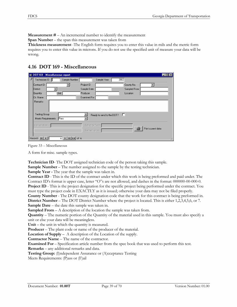
FDCS Georgia Department of Transportation
Measurement # – An incremental number to identify the measurement Span Number – the span this measurement was taken from Thickness measurement -The English form requires you to enter this value in mils and the metric form requires you to enter this value in microns. If you do not use the specified unit of measure your data will be wrong.
4.16 DOT 169 - Miscellaneous
Figure 33 – Miscellaneous
A form for misc. sample types. Technician ID- The DOT assigned technician code of the person taking this sample. Sample Number – The number assigned to the sample by the testing technician. Sample Year - The year that the sample was taken in. Contract ID - This is the ID of the contract under which this work is being preformed and paid under. The Contract ID’s format is upper case, letter “O”s are not allowed, and dashes in the format: 000000-00-000-0. Project ID - This is the project designation for the specific project being performed under the contract. You must type the project code in EXACTLY as it is issued; otherwise your data may not be filed properly. County Number - The DOT county designation code that the work for this contract is being preformed in. District Number – The DOT District Number where the project is located. This is either 1,2,3,4,5,6, or 7. Sample Date – the date this sample was taken in. Sampled From – A description of the location the sample was taken from. Quantity – The numeric portion of the Quantity of the material used in this sample. You must also specify a unit or else your data will be meaningless. Unit – the unit in which the quantity is measured. Producer – The plant code or name of the producer of the material. Location of Supply – A description of the Location of the supply. Contractor Name – The name of the contractor. Examined For – Specification article number from the spec book that was used to perform this test. Remarks – any additional remarks and data. Testing Group: (I)ndependent Assurance or (A)cceptance Testing Meets Requirements: (P)ass or (F)ail
Document Number: 01.00T Page 39 of 70 Version Number: 01.00

FDCS Georgia Department of Transportation
4.17 DOT 162 - Bridge Painting Conditions
Figure 34 - Bridge Painting Condition
Technician ID- The DOT assigned technician code of the person taking this sample. Sample Number– The number assigned to the sample by the testing technician. Sample Year– The year that the sample was taken in. Contract ID - This is the ID of the contract under which this work is being preformed and paid under. The Contract ID’s format is upper case, letter “O”s are not allowed, and dashes in the format: 000000-00-000-0. Project ID - This is the project designation for the specific project being performed under the contract. You must type the project code in EXACTLY as it is issued; otherwise your data may not be filed properly. District Number – The DOT District Number where the project is located. This is either 1,2,3,4,5,6, or 7. Sample Date – the date this sample was taken Bridge Location – The name or a description of the location of the bridge. Span Checked – The number that represents the span the sample was taken on from the bridge. Paint System – The number of the painting system specification used on this location. Prime Contractor Code – The code of the contractor performing this project. Paint Contractor Code – The code of the subcontractor performing the painting. Anchor Pattern – The measured roughness of the steel beam. The English form requires you to enter this value in mils and the metric form requires you to enter this value in microns. If you do not use the specified unit of measure your data will be wrong. Air Temperature – The ambient air temperature bridge location. The English form requires you to enter this value in °F and the metric form requires you to enter this value in °C. If you do not use the specified unit of measure your data will be wrong. Steel Surface Temperature – The measured temperature of the steel from the bridge. The English form requires you to enter this value in °F and the metric form requires you to enter this value in °C. If you do not use the specified unit of measure your data will be wrong. Relative Humidity % - The measured percent humidity at the bridge location Dew Point – The measured dew point temperature at the bridge location. The English form requires you to enter this value in °F and the metric form requires you to enter this value in °C. If you do not use the specified unit of measure your data will be wrong. MEK Rub Test – The visual measurement (1 to 10) of the quality of the coating Coating 1 – Measurement of the thickness of each paint coating as measured using the Tooke gauge. The English form requires you to enter this value in mils and the metric form requires you to enter this value in microns. If you do not use the specified unit of measure your data will be wrong.
Document Number: 01.00T Page 40 of 70 Version Number: 01.00

FDCS Georgia Department of Transportation
Coating 2 – Measurement of the thickness of each paint coating as measured using the Tooke gauge. The English form requires you to enter this value in mils and the metric form requires you to enter this value in microns. If you do not use the specified unit of measure your data will be wrong. Coating 3 – Measurement of the thickness of each paint coating as measured using the Tooke gauge. The English form requires you to enter this value in mils and the metric form requires you to enter this value in microns. If you do not use the specified unit of measure your data will be wrong. Remarks – any additional remarks Sampling Group: (I)ndependent Assurance or (A)cceptance Testing Meets Requirements: (P)ass or (F)ail.
4.18 DOT 165 - Galvanized Coating
Figure 35 - Galvanized Coating
Technician ID - The DOT assigned technician code of the person taking this sample. Sample Number - The number assigned to the sample by the testing technician. SampleYear - The year that the sample was taken in. Contract ID - This is the ID of the contract under which this work is being preformed and paid under. The Contract ID’s format is upper case, letter “O”s are not allowed, and dashes in the format: 000000-00-000-0. Project ID - This is the project designation for the specific project being performed under the contract. You must type the project code in EXACTLY as it is issued; otherwise your data may not be filed properly. County Number - The DOT county designation code that the work for this contract is being preformed in. District Number – The DOT District Number where the project is located. This is either 1,2,3,4,5,6, or 7. Sample Date – the date that this sample was taken on Contractor Code – The code for the contractor performing this project Sampled from – A description of the location the sample was taken from Producer Name –The name of the plant or contractor where the material came from Vendor Name –The name of the vendor who sold the material. Material – The coated galvanized material being tested such as Guardrail, bolt nut, post, etc. GaugeReading1 – The gauge measurement of the thickness of the galvanized coating. The English form requires you to enter this value in mils and the metric form requires you to enter this value in microns. If you do not use the specified unit of measure your data will be wrong. GaugeReading2 – The gauge measurement of the thickness of the galvanized coating. The English form requires you to enter this value in mils and the metric form requires you to enter this value in microns. If you do not use the specified unit of measure your data will be wrong.
Document Number: 01.00T Page 41 of 70 Version Number: 01.00

FDCS Georgia Department of Transportation
GaugeReading3 – The gauge measurement of the thickness of the galvanized coating. The English form requires you to enter this value in mils and the metric form requires you to enter this value in microns. If you do not use the specified unit of measure your data will be wrong. GaugeReading4 – The gauge measurement of the thickness of the galvanized coating. The English form requires you to enter this value in mils and the metric form requires you to enter this value in microns. If you do not use the specified unit of measure your data will be wrong. GaugeReading5 – The gauge measurement of the thickness of the galvanized coating. The English form requires you to enter this value in mils and the metric form requires you to enter this value in microns. If you do not use the specified unit of measure your data will be wrong. GaugeReading6 – The gauge measurement of the thickness of the galvanized coating. The English form requires you to enter this value in mils and the metric form requires you to enter this value in microns. If you do not use the specified unit of measure your data will be wrong. Average Reading – (CALCULATED) The average of the 6 gauge readings Measured Thickness – The measured thickness of the galvanized coating. . The English form requires you to enter this value in oz/ft² and the metric form requires you to enter this value in g/m². If you do not use the specified unit of measure your data will be wrong. Required Measured Thickness - The specified required thickness of the galvanized coating. The English form requires you to enter this value in oz/ft² and the metric form requires you to enter this value in g/m². If you do not use the specified unit of measure your data will be wrong. Remarks – any additional remarks and data. Testing Group: (I)ndependent Assurance or (A)cceptance Testing Meets Requirements: (P)ass or (F)ail.
4.19 DOT 116 - Pipe Certification and Quality
A comparison to check the certification and quality of pipe. Technician ID - The DOT assigned technician code of the person taking this sample. Sample Number - The number assigned to the sample by the testing technician. SampleYear - The year that the sample was taken in. Contract ID - This is the ID of the contract under which this work is being preformed and paid under. The Project ID - This is the project designation for the specific project being performed under the contract. County Number - The DOT county designation code that the work for this contract is being preformed in. District Number – The DOT District Number where the project is located. This is either 1,2,3,4,5,6, or 7. Sample Date – the date that this sample was taken on
Document Number: 01.00T Page 42 of 70 Version Number: 01.00

FDCS Georgia Department of Transportation
Plant Code – The plant code, if applicable, of the manufacturer of the pipe. Manufacturer Name - The name of the manufacture of the pipe.
4.19.1
4.19.2
Corrugated Aluminum or Steel
Pipe Material – (G)alvanized steel, (A)luminized steel, or a(L)uminum alloy. Pipe Coating – (P)lain, (A) – fully coated, (B) –half coated and paved, or (C) – fully coated and paved, (D) – fully coated and 100%paved or limed. Heat Number – The reference code from the pipe that identifies the batch the manufacturer produced it in. Pipe Gauge – The measured gauge of the pipe Pipe Diameter – the measured diameter of the pipe. The English form requires you to enter this value in inches and the metric form requires you to enter this value in millimeters. If you do not use the specified unit of measure your data will be wrong. Inspection Tag Number – the reference number that the plant inspector stamps on to the pipe.
Concrete Pipe
No. Sections Inspected – Number of sections inspected Class & Wall – Certification information stamped inside pipe. Diameter of pipe - the measured diameter of the section of pipe being tested. The English form requires you to enter this value in inches and the metric form requires you to enter this value in millimeters. If you do not use the specified unit of measure your data will be wrong. Length of section of pipe – The length of the section of pipe being tested. The English form requires you to enter this value in feet and the metric form requires you to enter this value in meters. If you do not use the specified unit of measure your data will be wrong. Date Made – date the piece of pipe was produced. GDT or CPT number – certification code obtained form the pipe. Remarks – any additional remarks Sampling Group: (I)ndependent Assurance or (A)cceptance Testing (Currently Testing management) Meets Requirements: (P)ass or (F)ail.
Document Number: 01.00T Page 43 of 70 Version Number: 01.00

FDCS Georgia Department of Transportation
4.20 DOT 150 - Control Strip and Asphaltic Compaction
Figure 36 - Control Strip and Asphaltic Compaction
Plant Number – The numeric designation of the asphalt plant producing the mix. Project ID – The project code from the DOT contract Type Mix - The GDOT Mix designation for the mix being tested. This must be a valid mix code selected from the dropdown list. Lot - The lot code number of the mix being tested Level – The level of the mix County Number – The DOT county designation code that the work for this contract is being preformed in. District Number – The DOT District Number where the project is located. This is either 1,2,3,4,5,6, or 7. Sample Date – the date that this sample was taken Contract ID – a unique id for a given contract. Technician Code – The technician’s GDOT assigned technician code. Prime Contractor Code: The ID code of the paving contractor placing the mix. Prime Contractor Name – The prime contractor's name. Plant Location – A description of the location of the plant Area Engineer No. - Area Engineer in charge of project Item No. - The item number for the material the test is being run on Percent AC – The percent of AC in the mix: (One decimal place) Blend - The blend of the mix, you may select RAP, Virgin, PM RAP, PM Virgin, Gilsonite, or you may enter a different blend. Gauge Info Gauge Number – The number assigned to the gauge by the OMR. (from list of gauges) Gauge Mode – the selected mode on the gauge used to take the samples. (from list of modes) Calibration Factor 1 – (CALCULATED) calibration factor from factor table for this gauge Calibration Factor 2 – (CALCULATED) calibration factor from factor table for this gauge Control Strip – Check this box if the test is of a control strip. Density Standard Count – The standard count measured by the gauge Correction Factor - The density standard count correction factor for that Asphalt Mix Corrected Standard Count – (CALCULATED) = Density Standard Count + the Correction Factor
Document Number: 01.00T Page 44 of 70 Version Number: 01.00

FDCS Georgia Department of Transportation
Use Nuclear or Core Results – Use the results from the nuclear tests or the core tests to use in the following calculations. Average Density Theoretical Density – The specified density of the material. . The English form requires you to enter this value in lbs/ft³ and the metric form requires you to enter this value in kg/m³. If you do not use the specified unit of measure your data will be wrong. Target Density – (CALCULATED for control strips only) The average of the core densities from the nuclear or core tests depending on which one is to be used. The English form requires you to enter this value in lbs/ft³ and the metric form requires you to enter this value in kg/m³. If you do not use the specified unit of measure your data will be wrong. Percent of Theoretical Density (CALCULATED) = Target Density / Theoretical Density *100 Max % air voids - Specified maximum percent air voids i.e. (normally 7.8 or 8.3 but may be other) Average Compaction – (CALCULATED) average of the percent compaction field from the nuclear or core test depending on which one is to be used. Average Voids – (CALCULATED) average of the percent voids field from the nuclear or core test depending on which one is to be used. Compaction Range- (CALCULATED) Compaction range percent (diff. between high and low compaction) Void Range – (CALCULATED) Void range percent (diff. between high and low void) Remarks Testing Group: (I)ndependent Assurance or (A)cceptance Testing Meets Requirements: (P)ass or (F)ail Test Section Test Number - A number between 1and 10 that identifies which test on this report this is. Technician ID – The technician’s GDOT assigned technician code Sample Number – The number assigned to the sample by the testing technician. Sample Year – The year in which this sample was taken Begin Station Number 1 – The station at which this sublot begins. This is measured in Linear Feet from the start of the project in English, and Linear Meters in metric. In English it is formatted, as 16+30 which means the station is 1630 feet from the start of the project. In metric it is formatted 4+360 which means the station is 4360 meters from the start of the project. End Station Number 1– The station at which this sublot ends. The station number where this test is performed. This is measured in Linear Feet from the start of the project in English, and Linear Meters in metric. In English it is formatted, as 16+30 which means the station is 1630 feet from the start of the project. In metric it is formatted 4+360 which means the station is 4360 meters from the start of the project. Length 1– The length of the project. The English form requires you to enter this value in feet and the metric form requires you to enter this value in meters. If you do not use the specified unit of measure your data will be wrong. Lane Location 1– A description of which lane the sample was taken from Begin Station Number 2– The station at which this sublot begins. This is measured in Linear Feet from the start of the project in English, and Linear Meters in metric. In English it is formatted, as 16+30 which means the station is 1630 feet from the start of the project. In metric it is formatted 4+360 which means the station is 4360 meters from the start of the project. End Station Number 2– The station at which this sublot ends. This is measured in Linear Feet from the start of the project in English, and Linear Meters in metric. In English it is formatted, as 16+30 which means the station is 1630 feet from the start of the project. In metric it is formatted 4+360 which means the station is 4360 meters from the start of the project. Length 2– The length of the project. The English form requires you to enter this value in feet and the metric form requires you to enter this value in meters. If you do not use the specified unit of measure your data will be wrong. Lane Location 2– A description of which lane the sample was taken from.
Document Number: 01.00T Page 45 of 70 Version Number: 01.00

FDCS Georgia Department of Transportation
Random Position – A random value between 0 and 1 that represents the position between the beginning and end of the project from which this sample is to be taken. (Three decimal places) (This value is filled automatically when the record is generated but the user can overwrite this value) Sampled Station Number – The actual station where the sample was taken. This is measured in Linear Feet from the start of the project in English, and Linear Meters in metric. In English it is formatted, as 16+30 which means the station is 1630 feet from the start of the project. In metric it is formatted 4+360 which means the station is 4360 meters from the start of the project. Transverse Locations - The random number that selects the transverse test locations Nuclear results, test method GDT59 Nuclear Left - Gauge density count measurement on left side of lane. Nuclear Center – Gauge density count measurement in the center of lane. Nuclear Right – Gauge density count measurement on the right side of lane. Nuclear Average – (Calculated, stored) The density count measurement of Left, Center and Right. (no decimals) Nuclear Density Count Ratio – (CALCULATED) = Density Count / (Density Standard Count + Density Correction Factor) Nuclear Density – (CALCULATED) The density calculated from the gauge readings = (log(Density Count Ratio, stored) – Calibration Factor 2) / Calibration Factor 1. Lbs/ft³ for English and kg/m³ for metric Nuclear Percent Compaction – (CALCULATED) = (Density/target density) x 100 Nuclear Percent Voids – (CALCULATED)= abs((Density/Theo Density) -1) x100 Core results Test Method GDT 39 Core Weight Air - Weight of dry sample in air in grams. Core Weight Surf. Air - Weight of surface-dry sample in air in grams. Core Weight Water - Weight of sample in water in grams. Core Difference – (CALCULATED) = Core Weight Surface Air – Core Weight Water Core Specific Gravity – (CALCULATED) = Core Weight Air / (Core Weight Surf. Air – Core Weight Water) Core Density - (CALCULATED) The density calculated from the core test. = Core Specific Gravity * 62.42 lb/ft³ for English or Core Specific Gravity * 1000 kg/m³ for metric. (lbs/ft³ for English and kg/m³ for metric) Core Percent Compaction – (CALCULATED) = (Core Density/Target Density) * 100 Core Percent Voids – (CALCULATED) = abs((Core Density/Theo. Density)-1) * 100
4.21 Random Number Sampling Utility
The Asphaltic Concrete Random Sampling Utility is a utility that generates random asphaltic concrete load numbers. To create a list of random load numbers: 1. Enter your plant number, project ID, type of mix, mix level, and lot number. (These will be the only fields
you may edit when you start).
2. Click Create / Edit.
3. Fill in the remainder of the fields. A description of each field appears in the help bar at the bottom of the window.
4. After filling in the fields, check your data to make sure it is correct and then click Calculate. This will make the data you have entered permanent. A list of load numbers will appear in the output box at the right of the window, and the Print button will now be enabled.
5. To print a hard copy of the results, click the Print button to view the print preview, then click “File” and “Print” to print the preview.
Document Number: 01.00T Page 46 of 70 Version Number: 01.00

FDCS Georgia Department of Transportation
If you want to start another record, click New. This program stores all generated records in a database on your hard drive. This is done so that previous lists may be recalled should the need arise. Please note that once a random sampling list is generated you can not go back and make changes to the record. For your convenience, this program keeps track of the fields that rarely change. For example after you type in your plant number it will be there the next time you start a new report. You may type over the value in any of these fields, in which case the new value will be remembered. Note: Unlike the other databases the reports from this database are not uploaded to the DOT.
4.22 Generic Random Number Generator
Figure 37 - Generic Random Number Generator
This utility generates random numbers for tests that use random sampling. To use this utility, enter the range in which you want to generate these numbers (the range is inclusive), the numeric increment to use, and then click “Calculate”. This generates a list of 35 numbers (the amount that will fit on one printed page). If you wish to print the list of random numbers, click “Print sheet”
Document Number: 01.00T Page 47 of 70 Version Number: 01.00

FDCS Georgia Department of Transportation
4.23 Printing Aggregate Data and Statistical Reports
When you click the “Aggregate reports" button from the main menu, you will see the following screen:
Figure 38 - Aggregate Reports
From here you may generate the following reports: Before running any of the reports listed here, you must enter a range of dates that you wish to work with. Aggregate Quarry Rating: This is the same rating that the GDOT runs on your data in combination with all other received data. This, however, will enable you to get immediate results on your own local data that you have entered. Aggregate Quarry Rating Summary: A summary of the above rating report. For the remainder of these reports you may additionally select data for the plant, product, sampled from location, used in, meets requirement, and washed/unwashed values you specify. These are optional, however you must still specify a date range. Aggregate Quality 640 Report Sheet – This will print a sheet of all entered data for the specified 640 forms. Aggregate Quantity 641 Report Sheet – This will print a sheet of all entered data for the specified 641 forms. Total Tests Per Aggregate Product - Is a summary report that shows how many tests were performed per aggregate product. Aggregate Producer Statistical Reports - Generates averages and standard deviations of percent passing for all specified samples for each product.
Document Number: 01.00T Page 48 of 70 Version Number: 01.00
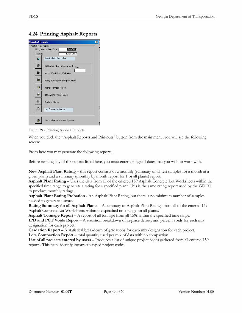
FDCS Georgia Department of Transportation
4.24 Printing Asphalt Reports
Figure 39 - Printing Asphalt Reports
When you click the “Asphalt Reports and Printouts" button from the main menu, you will see the following screen: From here you may generate the following reports: Before running any of the reports listed here, you must enter a range of dates that you wish to work with. New Asphalt Plant Rating – this report consists of a monthly (summary of all test samples for a month at a given plant) and a summary (monthly by month report for 1 or all plants) report. Asphalt Plant Rating – Uses the data from all of the entered 159 Asphalt Concrete Lot Worksheets within the specified time range to generate a rating for a specified plant. This is the same rating report used by the GDOT to produce monthly ratings. Asphalt Plant Rating Probation - An Asphalt Plant Rating, but there is no minimum number of samples needed to generate a score. Rating Summary for all Asphalt Plants – A summary of Asphalt Plant Ratings from all of the entered 159 Asphalt Concrete Lot Worksheets within the specified time range for all plants. Asphalt Tonnage Report – A report of all tonnage from all 159s within the specified time range. IPD and PCT Voids Report – A statistical breakdown of in-place density and percent voids for each mix designation for each project. Gradation Report – A statistical breakdown of gradations for each mix designation for each project. Lots Compaction Report – total quantity used per mix of data with no compaction. List of all projects entered by users – Produces a list of unique project codes gathered from all entered 159 reports. This helps identify incorrectly typed project codes.
Document Number: 01.00T Page 49 of 70 Version Number: 01.00

FDCS Georgia Department of Transportation
4.25 Importing External Data
The GDOT Field Data Collection System has the ability to import DOT640, DOT641 and OMR-049 data from external sources. This feature exists to enable Aggregate and Portland Cement producers who have their own database systems to automate importing of their data in to the DCS.
To use this feature: First create the text files with your data as per the specification found in "File Formats.doc" or "PC File Format RP.doc". Next place your text files in to the program's "import" folder (Usually this is located in "C:\Program Files\GDOTDCS\Import"). The Portland Cement import uses the folder "PCimport" (Which would be "C:\Program Files\GDOTDCS\PCimport"). Then start the DCS and click either the "Import Custom Portland Cement Files" button or the "Import Custom Aggregate Files" button. Click "OK" to begin importing. Once the data is imported you should remove the text files from the import folder; otherwise they will be re-imported the next time you use this feature.
Document Number: 01.00T Page 50 of 70 Version Number: 01.00
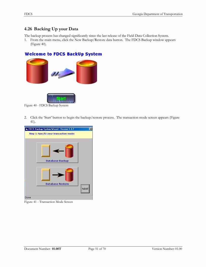
FDCS Georgia Department of Transportation
4.26 Backing Up your Data
The backup process has changed significantly since the last release of the Field Data Collection System. 1. From the main menu, click the New Backup/Restore data button. The FDCS Backup window appears
(Figure 40).
Figure 40 - FDCS Backup System
2. Click the ‘Start’ button to begin the backup/restore process. The transaction mode screen appears (Figure 41).
Figure 41 - Transaction Mode Screen
Document Number: 01.00T Page 51 of 70 Version Number: 01.00

FDCS Georgia Department of Transportation
4.26.1 Database Backup – New Backup
1. From the transaction mode screen, click the ‘Database Backup’ option (Figure 42)
Figure 42 - Database Backup Selected
2. Click the Next button, which will take you to the backup options screen appears (Figure 43).
Figure 43 - Backup Options
3. Select the New Backup option and click the Next button, which will take you to the backup file screen (Figure 44).
Document Number: 01.00T Page 52 of 70 Version Number: 01.00

FDCS Georgia Department of Transportation
Figure 44 - Backup File
4. Enter the backup file name. In the “your Full Name is” field, the system will name the file accordingly (Figure 45).
Figure 45 - File Name
5. Click the Next button. The file location screen appears (Figure 46).
Document Number: 01.00T Page 53 of 70 Version Number: 01.00

FDCS Georgia Department of Transportation
Figure 46 - File Location
6. Under the select drive field, select the drive where the file will reside. Under the directory field, double click the directory where the file resides. In the last field, verify the location is correct and click the Next button. The reports screen appears (Figure 47).
Figure 47 - Reports Selection
7. Select which reports you wish to back up. You can either select all of a type of reports (by click this ‘Select All’ button beneath the corresponding reports) or select individual types of reports. Once you determine which report(s), click the Next button. The report verification screen appears (Figure 48).
Document Number: 01.00T Page 54 of 70 Version Number: 01.00

FDCS Georgia Department of Transportation
Figure 48 – Backup Customization
8. From this point, you can back up all records or select which records you wish to back up. If you want to back up only a certain amount of records, click the ‘Let Me Choose’ option. The back up conditions screen appears (Figure 49).
Figure 49 - Back Up Conditions
9. Enter the back up conditions where applicable. Then Click the next button. The confirmation window appears (Figure 50).
Figure 50 - Confirmation of Back up
Document Number: 01.00T Page 55 of 70 Version Number: 01.00

FDCS Georgia Department of Transportation
4.26.1.1 Database Backup – Append
1. Follow steps one and two from the section prior. Instead of selecting ‘New Backup’, select ‘Append to an existing backup’. Click the Next button. The file location window appears (Figure 51).
Figure 51 - File Location
2. Under the select drive field, select the drive where the file resides. Under the directory field, double click the directory where the file resides. In the last field, verify the location is correct and click the Next button. The reports screen appears (Figure 52).
Figure 52 - Reports Selection
Document Number: 01.00T Page 56 of 70 Version Number: 01.00

FDCS Georgia Department of Transportation
3. Select which reports you wish to back up to the server. You can either select all of a type of reports (by click this ‘Select All’ button beneath the corresponding reports) or select individual types of reports. Once you determine which report(s), click the Next button. The backup customization screen appears (Figure 53).
Figure 53 - Backup Customization
4. From here, the user can either backup all or choose which ones to back up. Once selected, the User will see the following screen, upon completion of the backup or restoration process (Figure 54).
Figure 54 – Complete Screen
5. Click the exit button, which will take the user back to the Main Menu.
Document Number: 01.00T Page 57 of 70 Version Number: 01.00
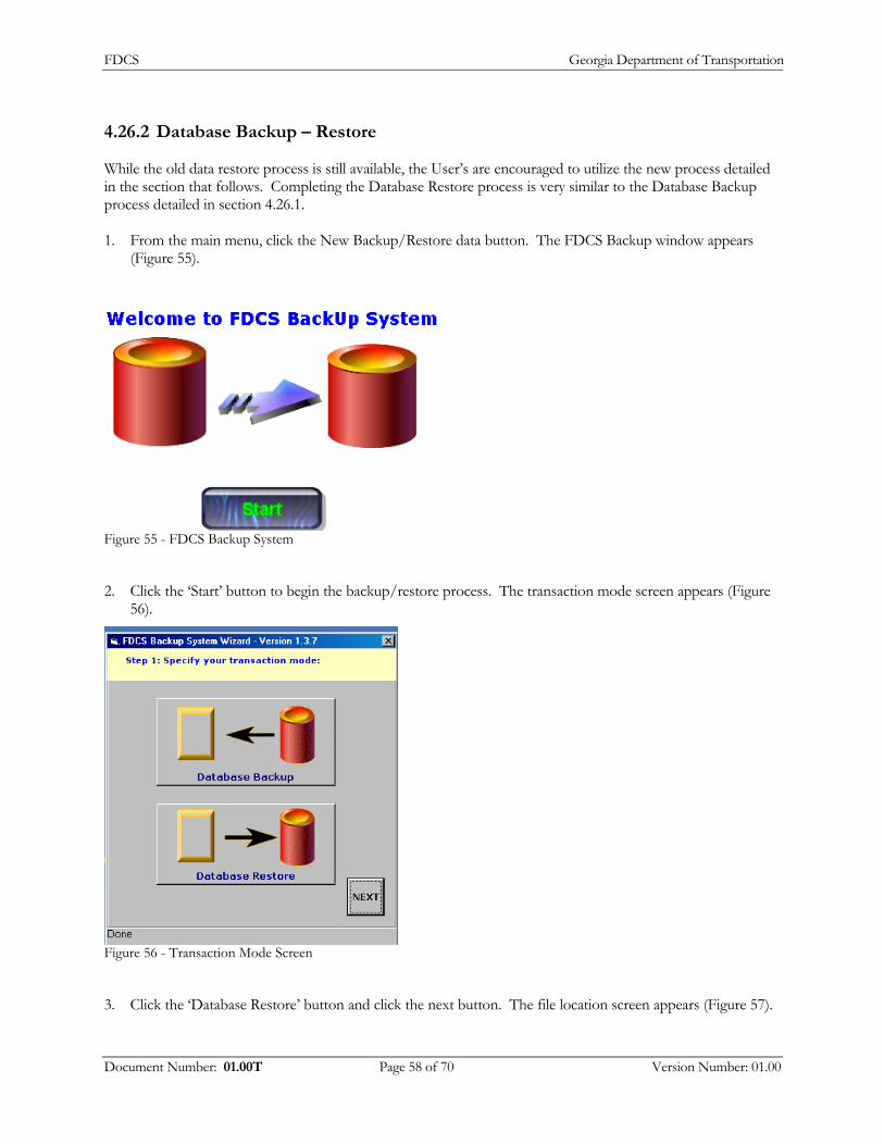
FDCS Georgia Department of Transportation
4.26.2 Database Backup – Restore
While the old data restore process is still available, the User’s are encouraged to utilize the new process detailed in the section that follows. Completing the Database Restore process is very similar to the Database Backup process detailed in section 4.26.1. 1. From the main menu, click the New Backup/Restore data button. The FDCS Backup window appears
(Figure 55).
Figure 55 - FDCS Backup System
2. Click the ‘Start’ button to begin the backup/restore process. The transaction mode screen appears (Figure 56).
Figure 56 - Transaction Mode Screen
3. Click the ‘Database Restore’ button and click the next button. The file location screen appears (Figure 57).
Document Number: 01.00T Page 58 of 70 Version Number: 01.00

FDCS Georgia Department of Transportation
Figure 57 - File Location - Restore
4. If you ordinarily restore data from your ‘A:’ drive and you do not have a disc in that drive, you may see the
following error . Click the OK button.
5. Under the select or enter location field, select the file location. Under the folder field, select the folder
where the file resides. And finally, double click the desired file. In the last field, verify the location is correct and click the Next button. The reports screen appears with all the options grayed out (Figure 58).
Figure 58 - Reports Restore
Document Number: 01.00T Page 59 of 70 Version Number: 01.00
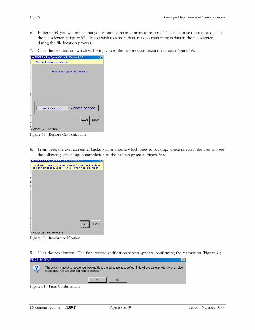
FDCS Georgia Department of Transportation
6. In figure 58, you will notice that you cannot select any forms to restore. This is because there is no data in the file selected in figure 57. If you wish to restore data, make certain there is data in the file selected during the file location process.
7. Click the next button, which will bring you to the restore customization screen (Figure 59).
Figure 59 - Restore Customization
8. From here, the user can either backup all or choose which ones to back up. Once selected, the user will see the following screen, upon completion of the backup process (Figure 54).
Figure 60 - Restore verification
9. Click the next button. The final restore verification screen appears, confirming the restoration (Figure 61).
Figure 61 - Final Confirmation
Document Number: 01.00T Page 60 of 70 Version Number: 01.00
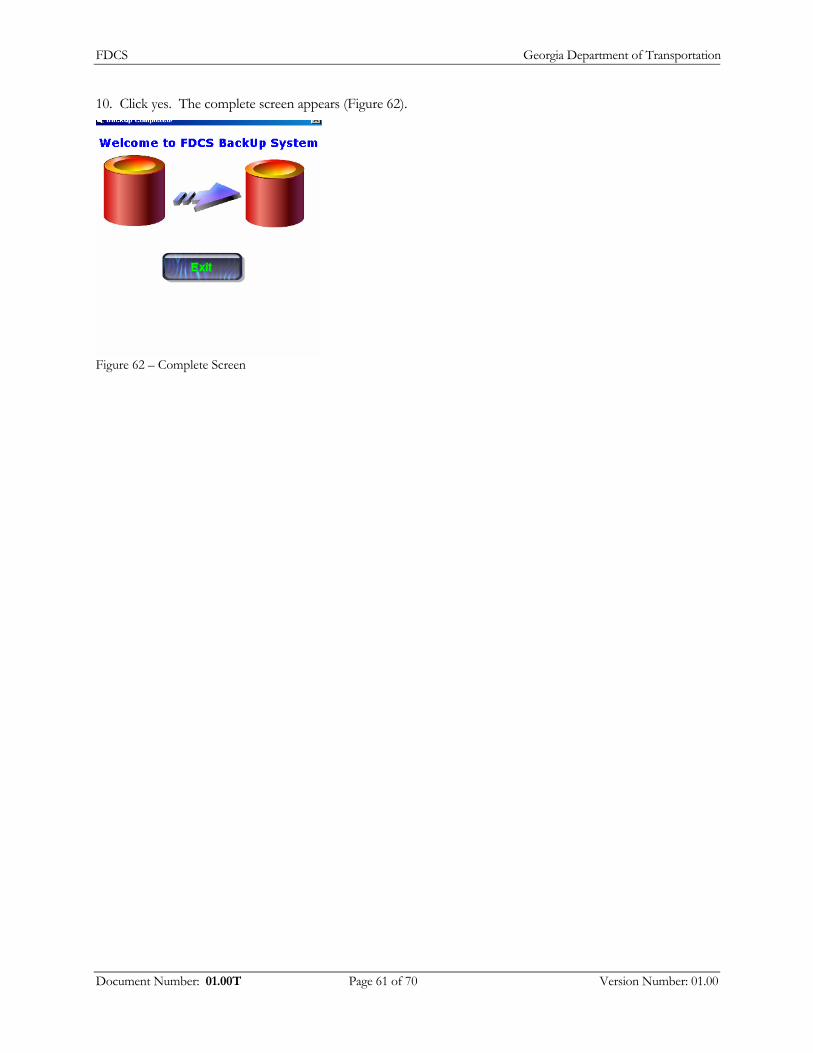
FDCS Georgia Department of Transportation
10. Click yes. The complete screen appears (Figure 62).
Figure 62 – Complete Screen
Document Number: 01.00T Page 61 of 70 Version Number: 01.00

FDCS Georgia Department of Transportation
4.27 Web Upload Process
The Web Upload process replaces the BBS process in versions prior. To perform this process, you must be connected to the internet (via Virtual Private Network (VPN) or your Internet Service Provider (ISP). Also, you will need to obtain login credentials (name and password) as provided by your Administrator. Once you have your login information and are connected to the internet, follow the steps detailed below to upload your information. 1. From the main menu, click the ‘Upload data to GDOT’ button in the lower left hand corner. The upload
options window appears (Figure 63).
Figure 63 - Upload Options
2. Click the ‘Web Upload’ option. The start screen options screen appears (Figure 64).
Figure 64 - Start screen
3. Click the Log in button in the top left hand corner. The log in screen appears (Figure 65).
Document Number: 01.00T Page 62 of 70 Version Number: 01.00

FDCS Georgia Department of Transportation
Figure 65 - Log In screen
4. Enter your account ID, password and TechCode. Verify the ‘Upload Files’ option (to the left) is selected. Click the ‘LogIn’ button. The Data Upload page appears (66).
Figure 66 - Data Upload Page
5. Simoteaneously, press the ‘Ctrl’ and ‘V’ keys. This will enter the information necessary in the data upload field. If the location entered is not correct, click the browse key and locate it manually. If you’ve successfully done the Ctrl-V step, your screen will look like the one below (Figure 67).
Document Number: 01.00T Page 63 of 70 Version Number: 01.00
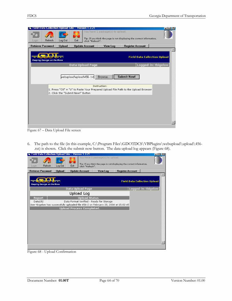
FDCS Georgia Department of Transportation
Figure 67 – Data Upload File screen
6. The path to the file (in this example, C:\Program Files\GDOTDCS\VBPlugins\webupload\upload\456-.txt) is shown. Click the submit now button. The data upload log appears (Figure 68).
Figure 68 - Upload Confirmation
Document Number: 01.00T Page 64 of 70 Version Number: 01.00
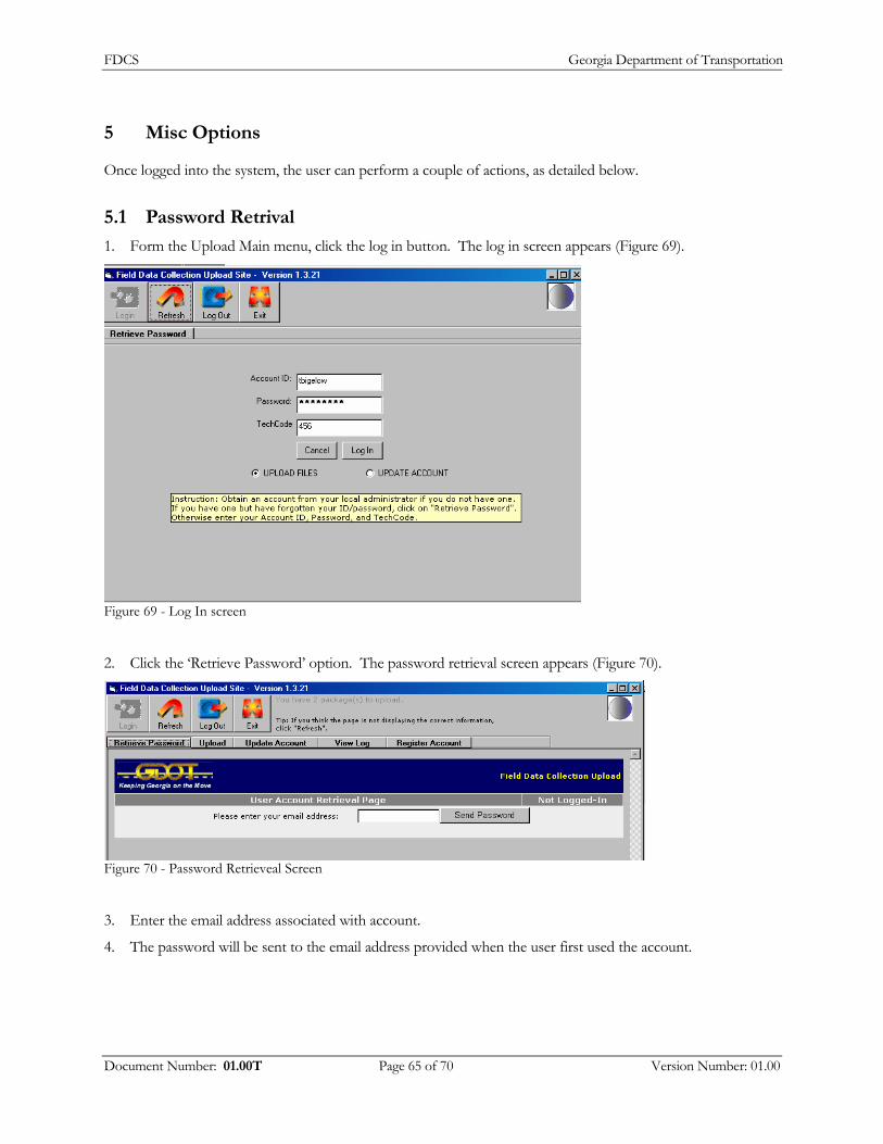
FDCS Georgia Department of Transportation
5 Misc Options
Once logged into the system, the user can perform a couple of actions, as detailed below.
5.1 Password Retrival
1. Form the Upload Main menu, click the log in button. The log in screen appears (Figure 69).
Figure 69 - Log In screen
2. Click the ‘Retrieve Password’ option. The password retrieval screen appears (Figure 70).
Figure 70 - Password Retrieveal Screen
3. Enter the email address associated with account.
4. The password will be sent to the email address provided when the user first used the account.
Document Number: 01.00T Page 65 of 70 Version Number: 01.00
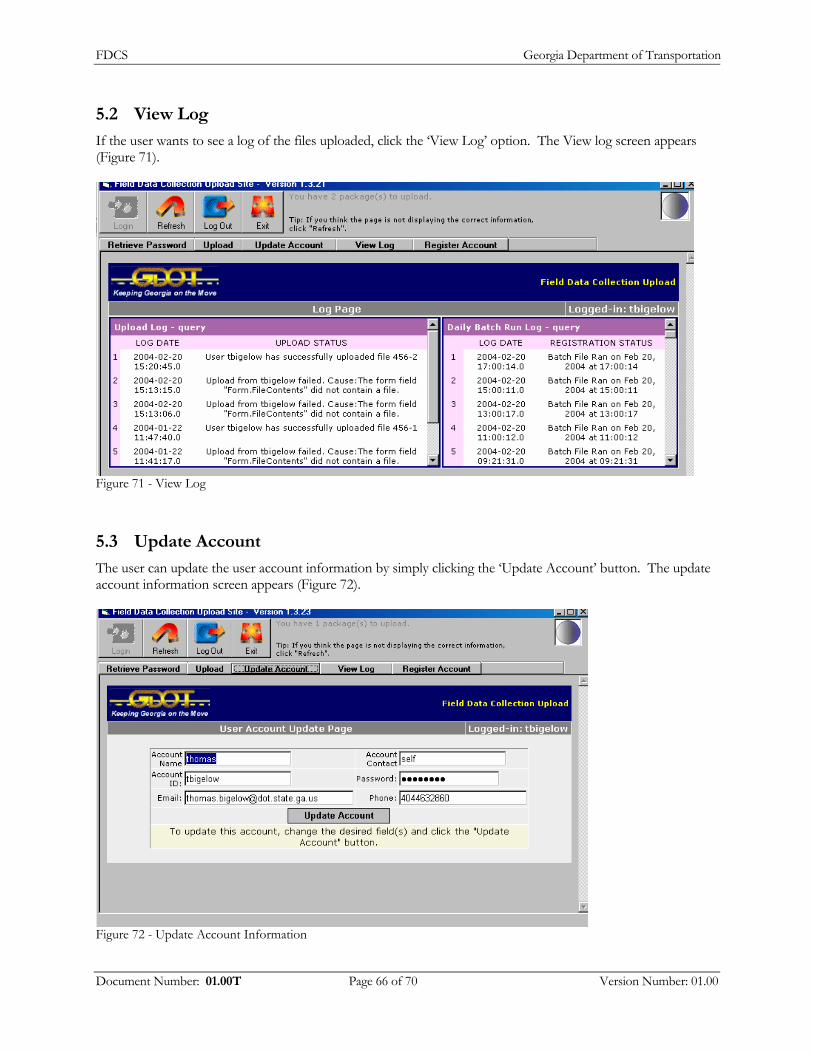
FDCS Georgia Department of Transportation
5.2 View Log
If the user wants to see a log of the files uploaded, click the ‘View Log’ option. The View log screen appears (Figure 71).
Figure 71 - View Log
5.3 Update Account
The user can update the user account information by simply clicking the ‘Update Account’ button. The update account information screen appears (Figure 72).
Figure 72 - Update Account Information
Document Number: 01.00T Page 66 of 70 Version Number: 01.00
FDCS Georgia Department of Transportation
6 Uploading Corrected Copies
To upload corrected or modified data that you have previously uploaded, you must call the GDOT Testing Management Field supervisor or Testing Management Operations Supervisor. They must remove the record (or records) that you wish to replace from their DOT Field Data Server Database. If you do not do this, your uploaded changes may be ignored as duplicate data. More information: Designated GDOT personnel verify all data uploaded. To prevent unauthorized alteration of verified data the system does not accept changes to existing verified records from data uploaded to the BBS. Because uploaded data is not immediately processed, there is no way to immediately alert you to problems accepting your data. Such problems are logged at the GDOT but they may or may not be noticed and handled. The only way to replace a record which has the same identifying (or "key") fields by uploading new data is to first have GDOT Testing Management remove your old record form their database and then re-upload your data. If you do not call to have the existing record removed your uploaded data may not be accepted.
Document Number: 01.00T Page 67 of 70 Version Number: 01.00

FDCS Georgia Department of Transportation
7 Troubleshooting
What to do if you have problems uploading? This Section covers common problems that you may come across while setting up or using the DOT Terminal Link.
7.1 Modem Does Not Dial
If the modem does not dial and if nothing appears in the terminal window, then check the following: If your modem is external, make sure you plugged it in, turned it on, and you connected it properly to your computer. Check the communications settings. Make sure you specified the correct communications port and baud rate.
7.2 Modem Dials, But there is No Answer
If you can hear the modem dial, but you do not hear the sounds of modems connecting, then check the following: Make sure you properly connected your modem to a phone line. Check the number you are dialing in the dialing settings. You may need to dial a "9" prefix to get an outside line.
7.3 Modem Connects but Text is garbled
If you successfully connect to the GDOT BBS, but the text in the terminal window appears garbled, and the auto-upload fails, then check the following: Check your communications settings. Make sure you have specified the correct baud rate for your modem. If the baud rate you selected is greater than 2400, try a lower baud rate. Check your phone line. A bad phone connection can cause this problem.
7.4 Modem Hangs up Unexpectedly
If other people have access to your line from other phones, make sure they do not pick up the phone while your computer is uploading. If you have call waiting, then you need to disable it by setting the *70 prefix in the Dialing Settings option.
7.5 Unable to open Comm port
If you get this error while starting the DOT Terminal Link, then check the following: Close any other communications program such as Windows Terminal, Hyper Terminal, Internet dial-up programs, or FAX modem programs. These programs lock the communications port for exclusive use. Make sure you specified a communication port that exists on your system.
Document Number: 01.00T Page 68 of 70 Version Number: 01.00
FDCS Georgia Department of Transportation
7.6 Everything was working fine, but suddenly the modem won't work
Try powering down the computer and the modem and restarting. Double-check the settings, in case someone else changed them.
Document Number: 01.00T Page 69 of 70 Version Number: 01.00

FDCS Georgia Department of Transportation
8 Contacting the GDOT for support
You may contact the GDOT IT Division Solutions Center for assistance with this software, however before you do you must do the following things: 1. 1: Check for a new version of this software. If you have run in to a problem with the program, it may have
already been fixed in the latest version. Additionally the Solutions Center only provides support for current version of the DCS.
2. Upgrade to the latest sofrware at http://tomcat2.dot.state.ga.us/fdcs/upgrade/fdcsupgrade2.cfm.
3. If you have not already read it, read this manual. Most usage problems can be answered by reading the manual.
4. Write down any error messages you are getting exactly as they appear on your computer's screen. Do not paraphrase them.
5. Be at your computer when calling the GDOT IT Division Solutions Center. You may be asked to do things to your computer while talking to them.
6. The phone number for the GDOT IT Division Solutions Center is 404-651-5010. The first available Solution Provider will take your call.
Document Number: 01.00T Page 70 of 70 Version Number: 01.00