Embed Size (px)
Citation preview
George Mason University Allen Walker Art & Visual Technology Building Lighting / Electrical Option
Page 128
Structural Breadth
Upon the redesign of the typical painting studio, the original clerestory design was switched to a
skylight system. While this created the opportunity for a more uniform distribution of daylight, it
also required modification to the existing system. The existing roof design made use of a 3” Type N
Deep-Rib Steel Decking. The beams to be redesigned were assumed to be fully braced due to the
metal decking and skylights. Therefore, sizing of members was based on the Steel Construction
manual table 3-2.
Please note that the scope of this depth is limited to the resizing and cost analysis of the structural
members only.
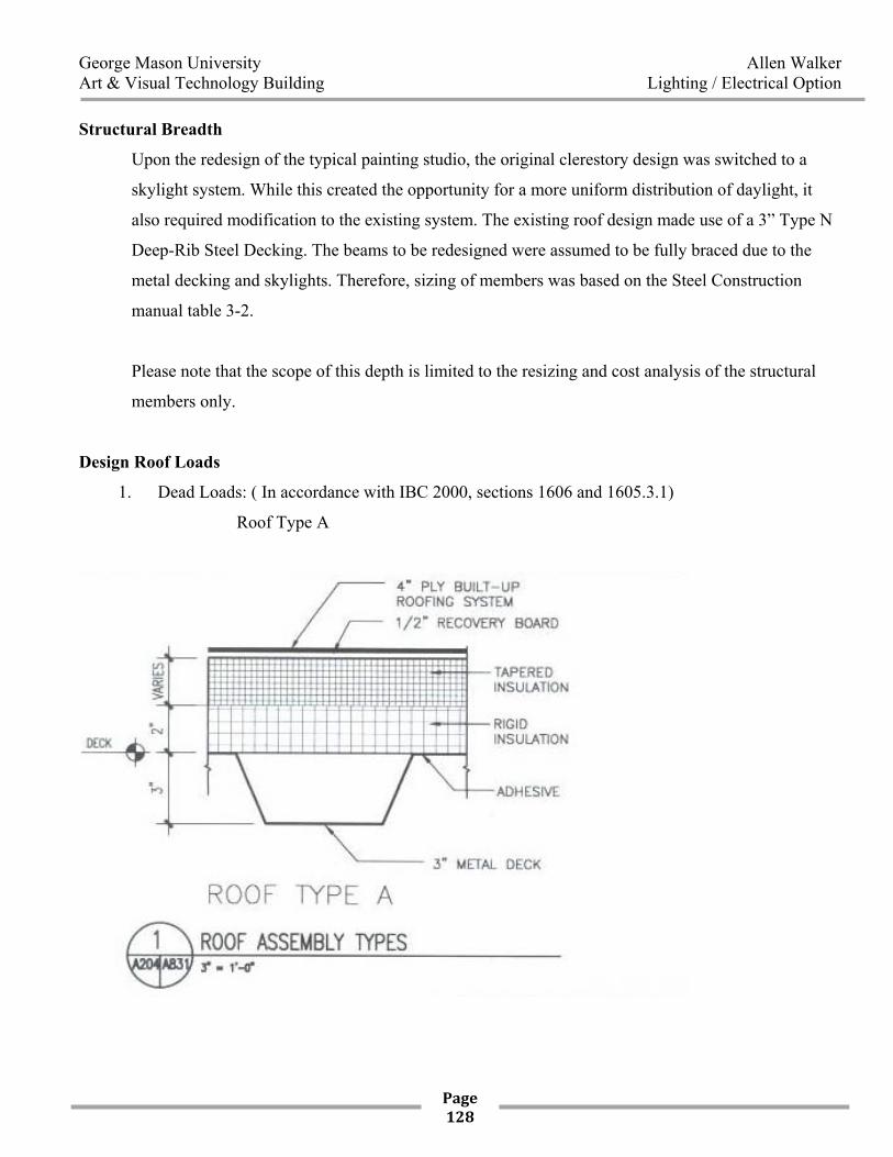
Design Roof Loads
1. Dead Loads: ( In accordance with IBC 2000, sections 1606 and 1605.3.1)
Roof Type A
George Mason University Allen Walker Art & Visual Technology Building Lighting / Electrical Option
Page 129
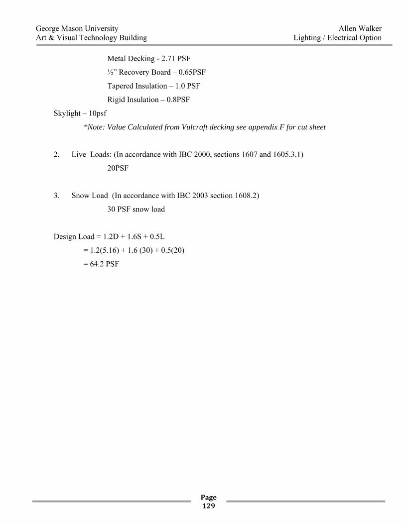
Metal Decking - 2.71 PSF
½” Recovery Board – 0.65PSF
Tapered Insulation – 1.0 PSF
Rigid Insulation – 0.8PSF
Skylight – 10psf
*Note: Value Calculated from Vulcraft decking see appendix F for cut sheet
2. Live Loads: (In accordance with IBC 2000, sections 1607 and 1605.3.1)
20PSF
3. Snow Load (In accordance with IBC 2003 section 1608.2)
30 PSF snow load
Design Load = 1.2D + 1.6S + 0.5L
= 1.2(5.16) + 1.6 (30) + 0.5(20)
= 64.2 PSF
George Mason University Allen Walker Art & Visual Technology Building Lighting / Electrical Option
Page 130
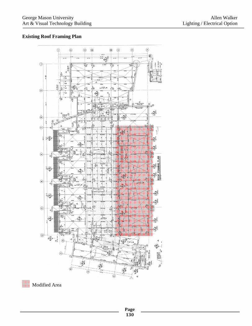
Existing Roof Framing Plan
Modified Area
George Mason University Allen Walker Art & Visual Technology Building Lighting / Electrical Option
Page 131
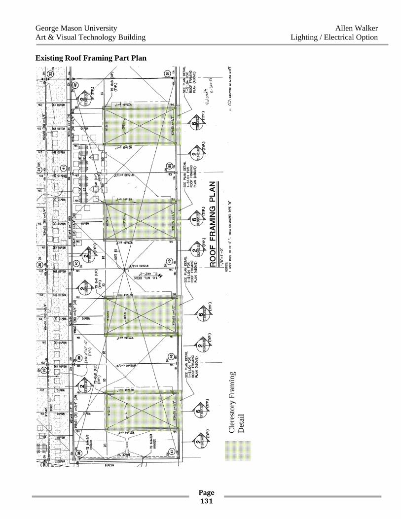
Existing Roof Framing Part Plan
Cle
rest
ory
Fram
ing
Det
ail
George Mason University Allen Walker Art & Visual Technology Building Lighting / Electrical Option
Page 132
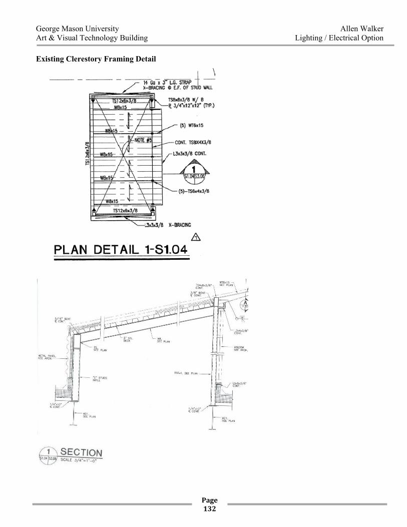
Existing Clerestory Framing Detail
George Mason University Allen Walker Art & Visual Technology Building Lighting / Electrical Option
Page 133
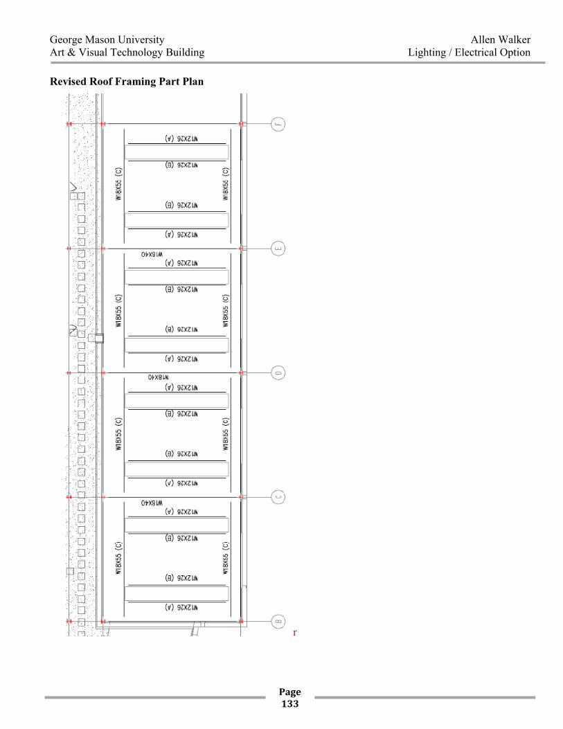
Revised Roof Framing Part Plan
r
George Mason University Allen Walker Art & Visual Technology Building Lighting / Electrical Option
Page 134
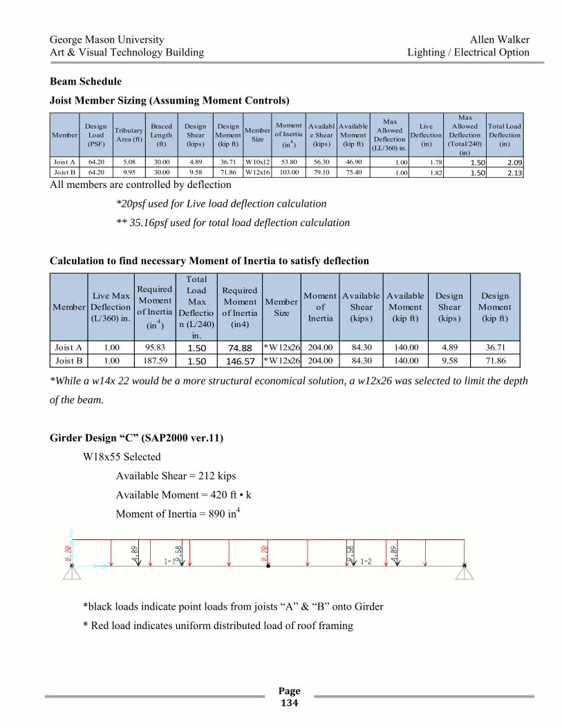
Beam Schedule
Joist Member Sizing (Assuming Moment Controls)
MemberDesign Load (PSF)
Tributary Area (ft)
Braced Length
(ft)
Design Shear (kips)
Design Moment (kip ft)
Member Size
Moment of Inertia
(in4)
Available Shear (kips)
Available Moment (kip ft)
Max Allowed
Deflection (LL/360) in.
Live Deflection
(in)
Max Allowed
Deflection (Total/240)
(in)
Total Load Deflection
(in)
Joist A 64.20 5.08 30.00 4.89 36.71 W10x12 53.80 56.30 46.90 1.00 1.78 1.50 2.09Joist B 64.20 9.95 30.00 9.58 71.86 W12x16 103.00 79.10 75.40 1.00 1.82 1.50 2.13
All members are controlled by deflection
*20psf used for Live load deflection calculation
** 35.16psf used for total load deflection calculation
Calculation to find necessary Moment of Inertia to satisfy deflection
MemberLive Max Deflection (L/360) in.
Required Moment of Inertia
(in4)
Total Load Max
Deflection (L/240)
in.
Required Moment of Inertia
(in4)
Member Size
Moment of
Inertia
Available Shear (kips)
Available Moment (kip ft)
Design Shear (kips)
Design Moment (kip ft)
Joist A 1.00 95.83 1.50 74.88 *W12x26 204.00 84.30 140.00 4.89 36.71Joist B 1.00 187.59 1.50 146.57 *W12x26 204.00 84.30 140.00 9.58 71.86
*While a w14x 22 would be a more structural economical solution, a w12x26 was selected to limit the depth
of the beam.
Girder Design “C” (SAP2000 ver.11)
W18x55 Selected
Available Shear = 212 kips
Available Moment = 420 ft • k
Moment of Inertia = 890 in4
*black loads indicate point loads from joists “A” & “B” onto Girder
* Red load indicates uniform distributed load of roof framing
George Mason University Allen Walker Art & Visual Technology Building Lighting / Electrical Option
Page 135
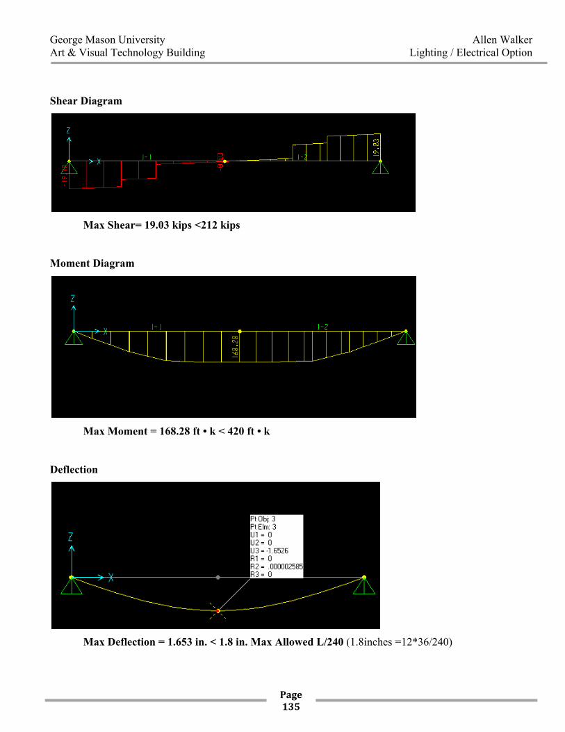
Shear Diagram
Max Shear= 19.03 kips <212 kips
Moment Diagram
Max Moment = 168.28 ft • k < 420 ft • k
Deflection
Max Deflection = 1.653 in. < 1.8 in. Max Allowed L/240 (1.8inches =12*36/240)
George Mason University Allen Walker Art & Visual Technology Building Lighting / Electrical Option
Page 136
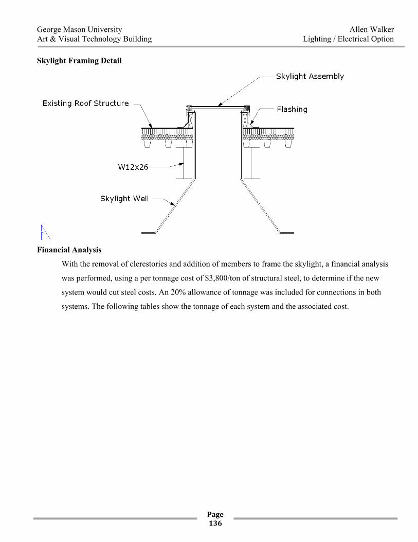
Skylight Framing Detail
Financial Analysis
With the removal of clerestories and addition of members to frame the skylight, a financial analysis
was performed, using a per tonnage cost of $3,800/ton of structural steel, to determine if the new
system would cut steel costs. An 20% allowance of tonnage was included for connections in both
systems. The following tables show the tonnage of each system and the associated cost.
George Mason University Allen Walker Art & Visual Technology Building Lighting / Electrical Option
Page 137
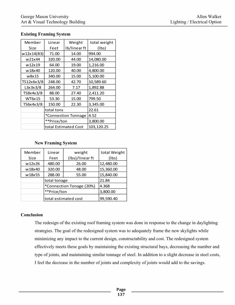
Existing Framing System
Member Size
Linear Feet
Weight lb/linear ft
total weight (lbs)
w12x14(B3) 71.00 14.00 994.00w21x44 320.00 44.00 14,080.00w12x19 64.00 19.00 1,216.00w18x40 120.00 40.00 4,800.00w8x15 340.00 15.00 5,100.00
TS12x6x3/8 248.00 42.70 10,589.60L3x3x3/8 264.00 7.17 1,892.88TS8x4x3/8 88.00 27.40 2,411.20WT6x15 53.30 15.00 799.50TS6x4x3/8 150.00 22.30 3,345.00
22.614.523,800.00103,120.25
total tons*Connection Tonnage**Price/tontotal Estimated Cost
New Framing System
Member Size
Linear Feet
weight (lbs)/linear ft
total Weight (lbs)
w12x26 480.00 26.00 12,480.00w18x40 320.00 48.00 15,360.00w18x55 288.00 55.00 15,840.00
21.844.3683,800.00
99,590.40
total tonage*Connection Tonage (20%)**Price/ton
total estimated cost
Conclusion
The redesign of the existing roof framing system was done in response to the change in daylighting
strategies. The goal of the redesigned system was to adequately frame the new skylights while
minimizing any impact to the current design, constructability and cost. The redesigned system
effectively meets these goals by maintaining the existing structural bays, decreasing the number and
type of joints, and maintaining similar tonnage of steel. In addition to a slight decrease in steel costs,
I feel the decrease in the number of joints and complexity of joints would add to the savings.