Embed Size (px)
Citation preview
ECE 333 © 2002 – 2021 George Gross, University of Illinois at Urbana-Champaign, All Rights Reserved. 1
ECE 333 – GREEN ELECTRIC ENERGY
6. Limits on Conversion of Wind Into Electricity
George Gross
Department of Electrical and Computer Engineering
University of Illinois at Urbana–Champaign
ECE 333 © 2002 – 2021 George Gross, University of Illinois at Urbana-Champaign, All Rights Reserved. 2
❑ We analytically characterize the power in wind as
a cubic function of the wind speed v
❑ The wind energy is in the form of kinetic energy,
whose extraction from the wind is used to rotate
the generator shaft mounted in the nacelle
❑ We examine the constraint – the so–called Betz
limit – that limits the ability of a wind turbine to
convert the wind kinetic energy into mechanical
energy to rotate the turbine generator shaft
CONVERSION OF WIND INTO ELECTRICITY
ECE 333 © 2002 – 2021 George Gross, University of Illinois at Urbana-Champaign, All Rights Reserved. 3
❑ The limit was derived in 1919 by Albert Betz, a
German physicist
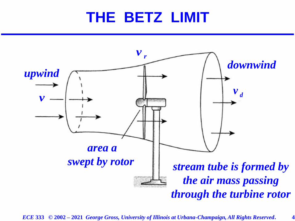
❑ We consider the wind as it passes through a wind
turbine rotor and we examine the wind stream
❑ We explain the conceptual basis on the limit of
the conversion of wind into electricity by means
of the diagram below
THE BETZ LIMIT
ECE 333 © 2002 – 2021 George Gross, University of Illinois at Urbana-Champaign, All Rights Reserved. 4
THE BETZ LIMIT
upwinddownwind
area a
swept by rotor stream tube is formed by
the air mass passing
through the turbine rotor
rv
dvv
ECE 333 © 2002 – 2021 George Gross, University of Illinois at Urbana-Champaign, All Rights Reserved. 5
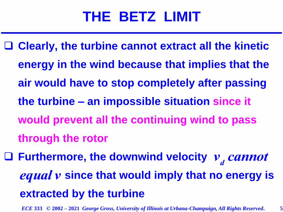
❑ Clearly, the turbine cannot extract all the kinetic
energy in the wind because that implies that the
air would have to stop completely after passing
the turbine – an impossible situation since it
would prevent all the continuing wind to pass
through the rotor
❑ Furthermore, the downwind velocity
since that would imply that no energy is
extracted by the turbine
THE BETZ LIMIT
v
dcannot
equal v
ECE 333 © 2002 – 2021 George Gross, University of Illinois at Urbana-Champaign, All Rights Reserved. 6
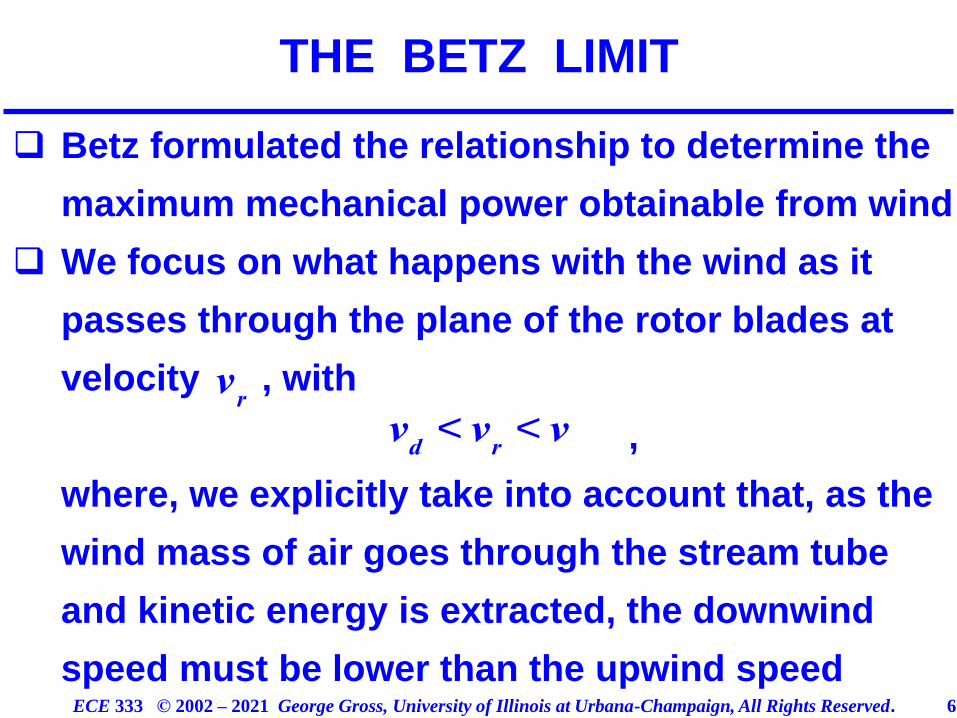
❑ Betz formulated the relationship to determine the
maximum mechanical power obtainable from wind
❑ We focus on what happens with the wind as it
passes through the plane of the rotor blades at
velocity , with
,
where, we explicitly take into account that, as the
wind mass of air goes through the stream tube
and kinetic energy is extracted, the downwind
speed must be lower than the upwind speed
THE BETZ LIMIT
v
r
v
d< v
r< v
ECE 333 © 2002 – 2021 George Gross, University of Illinois at Urbana-Champaign, All Rights Reserved. 7
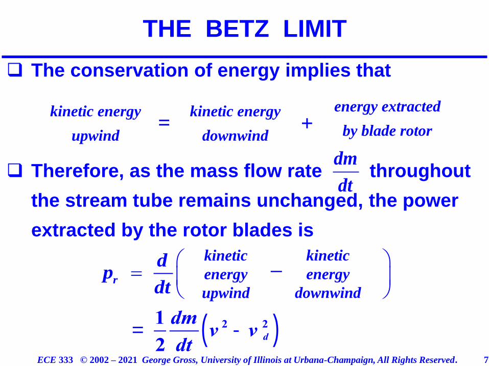
❑ The conservation of energy implies that
❑ Therefore, as the mass flow rate throughout
the stream tube remains unchanged, the power
extracted by the rotor blades is
THE BETZ LIMIT
kinetic energy
upwind
kinetic energy
downwind
energy extracted
by blade rotor+=
dm
dt
=
r
dp
dt
kinetic
energy
upwind
kinetic
energy
downwind
–
=
1
2
dm
dtv
2 - v d
2( )
ECE 333 © 2002 – 2021 George Gross, University of Illinois at Urbana-Champaign, All Rights Reserved. 8
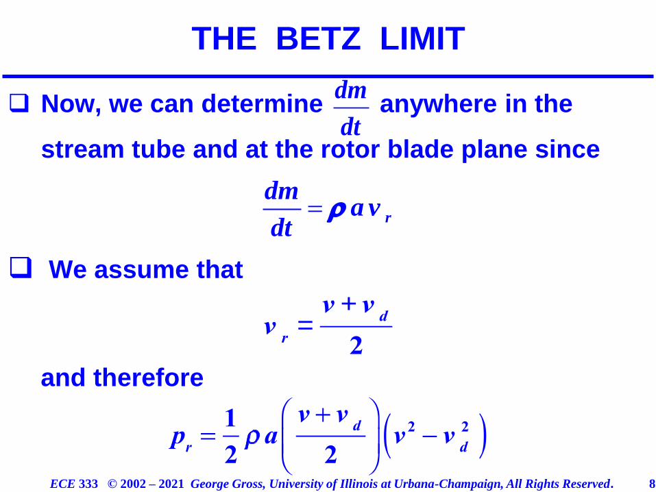
❑ Now, we can determine anywhere in the
stream tube and at the rotor blade plane since
❑ We assume that
and therefore
THE BETZ LIMIT
= r
dma v
dt
dm
dt
v
r=
v + vd
2
ECE 333 © 2002 – 2021 George Gross, University of Illinois at Urbana-Champaign, All Rights Reserved. 9
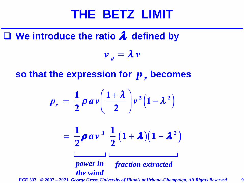
❑ We introduce the ratio defined by
so that the expression for becomes
THE BETZ LIMIT
rp
( )( )= + −3 21 11 1
2 2a v
power in
the windfraction extracted
ECE 333 © 2002 – 2021 George Gross, University of Illinois at Urbana-Champaign, All Rights Reserved. 10
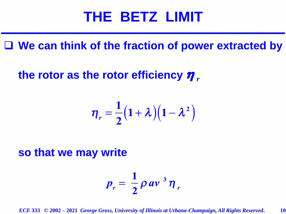
❑ We can think of the fraction of power extracted by
the rotor as the rotor efficiency
so that we may write
THE BETZ LIMIT
r
ECE 333 © 2002 – 2021 George Gross, University of Illinois at Urbana-Champaign, All Rights Reserved. 11
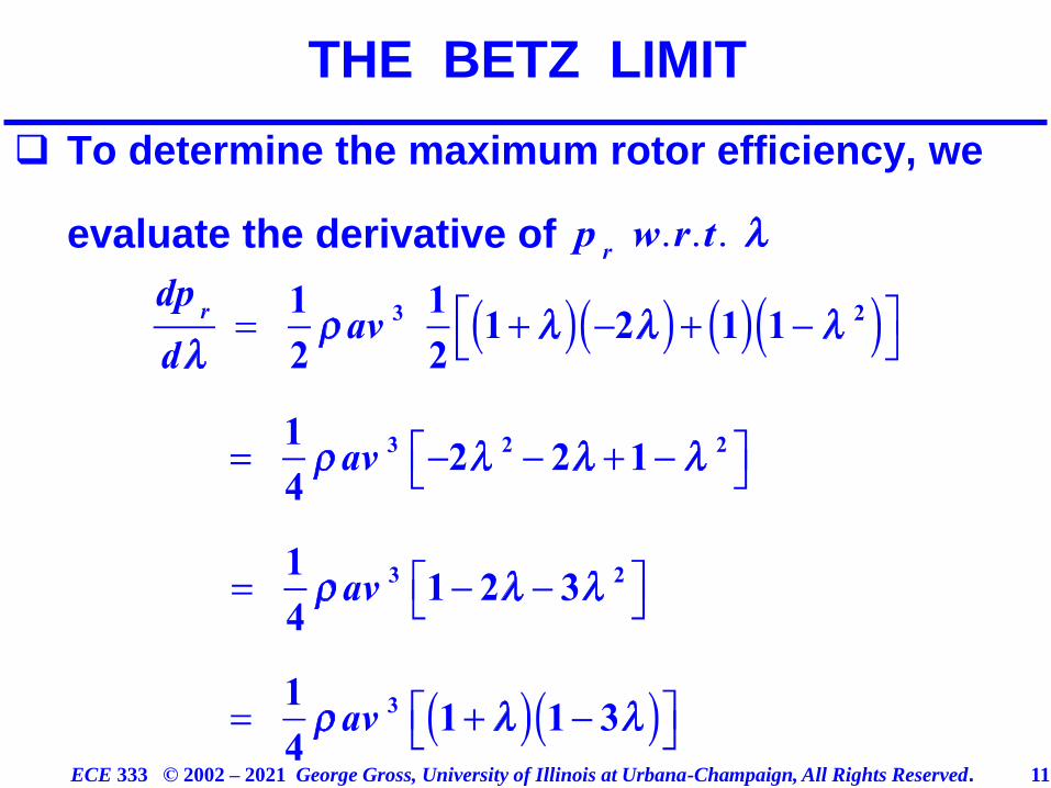
❑ To determine the maximum rotor efficiency, we
evaluate the derivative of
THE BETZ LIMIT
ECE 333 © 2002 – 2021 George Gross, University of Illinois at Urbana-Champaign, All Rights Reserved. 12
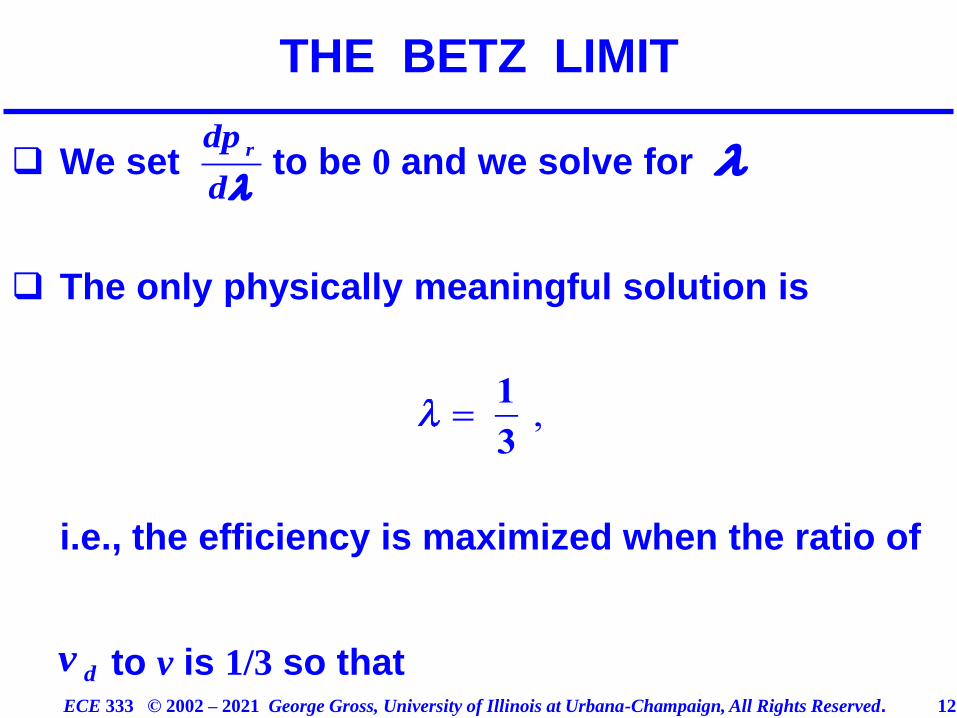
❑ We set to be 0 and we solve for
❑ The only physically meaningful solution is
i.e., the efficiency is maximized when the ratio of
to v is 1/3 so that
THE BETZ LIMIT
rdp
d
dv
ECE 333 © 2002 – 2021 George Gross, University of Illinois at Urbana-Champaign, All Rights Reserved. 13
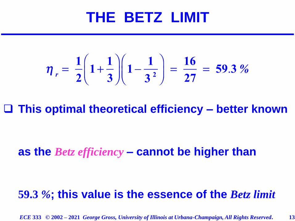
❑ This optimal theoretical efficiency – better known
as the Betz efficiency – cannot be higher than
59.3 %; this value is the essence of the Betz limit
THE BETZ LIMIT
ECE 333 © 2002 – 2021 George Gross, University of Illinois at Urbana-Champaign, All Rights Reserved. 14
❑ The Betz limit implies that even under ideal
conditions less than 60 % of the power in wind
can be extracted; indeed, in actual systems, the
best that is attainable is, typically, below 50 % – in
other words, at most half of the energy in wind
can be converted into mechanical energy to
rotate the generator shaft
THE BETZ LIMIT
ECE 333 © 2002 – 2021 George Gross, University of Illinois at Urbana-Champaign, All Rights Reserved. 15
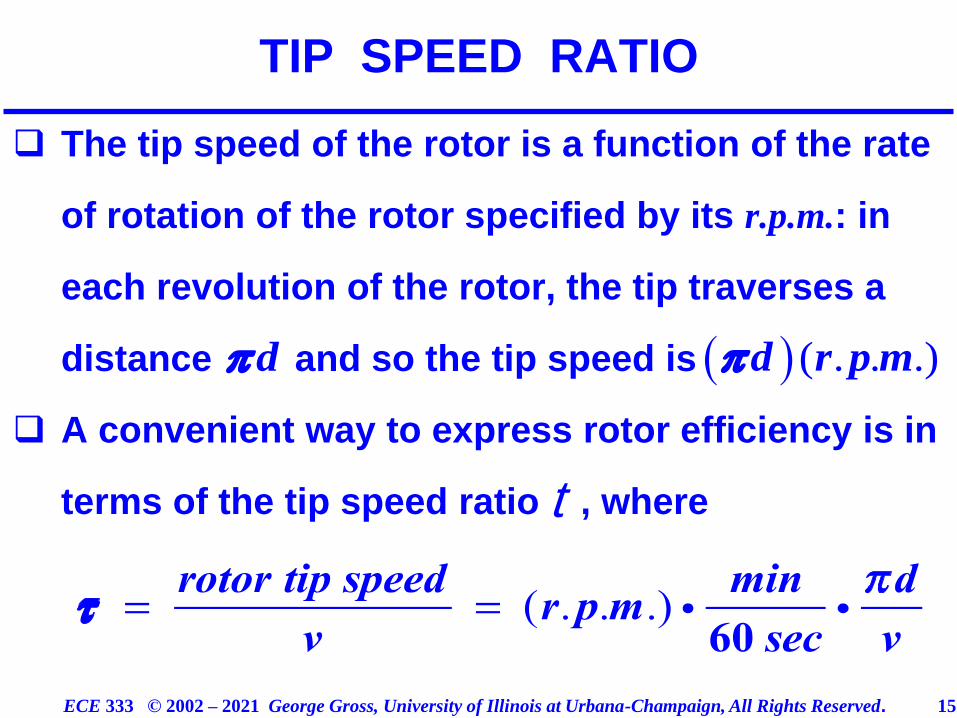
❑ The tip speed of the rotor is a function of the rate
of rotation of the rotor specified by its r.p.m.: in
each revolution of the rotor, the tip traverses a
distance and so the tip speed is
❑ A convenient way to express rotor efficiency is in
terms of the tip speed ratio , where
TIP SPEED RATIO
d ( ) ( . . .)d r p m
t
ECE 333 © 2002 – 2021 George Gross, University of Illinois at Urbana-Champaign, All Rights Reserved. 16
❑ Studies indicate that modern turbines attain maxi-
mum efficiency for : the tip of the blade
moves 4 – 6 times faster than the wind speed
❑ It follows that for maximum efficiency it is
desirable that turbine blades change their speed
as wind speed changes – as is the case in the so–
called variable speed generators
TIP SPEED RATIO
ECE 333 © 2002 – 2021 George Gross, University of Illinois at Urbana-Champaign, All Rights Reserved. 17
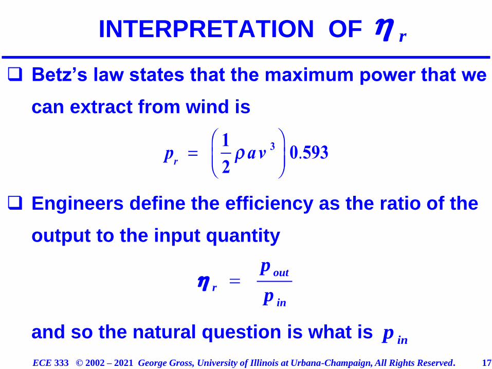
❑ Betz’s law states that the maximum power that we
can extract from wind is
❑ Engineers define the efficiency as the ratio of the
output to the input quantity
and so the natural question is what is
INTERPRETATION OF r
=out
r
in
p
p
inp
ECE 333 © 2002 – 2021 George Gross, University of Illinois at Urbana-Champaign, All Rights Reserved. 18
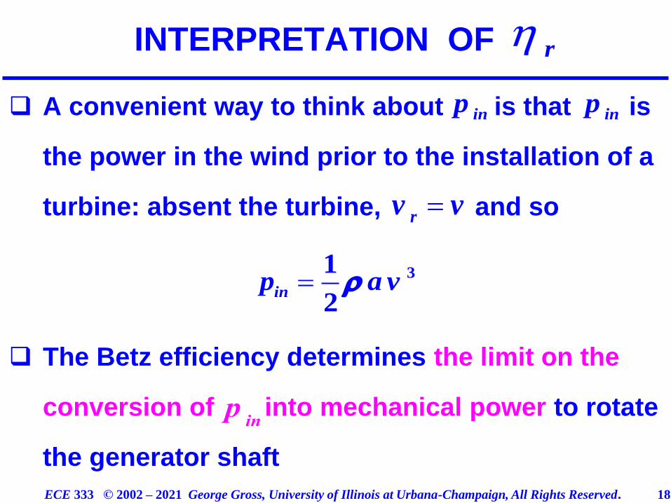
❑ A convenient way to think about is that is
the power in the wind prior to the installation of a
turbine: absent the turbine, and so
❑ The Betz efficiency determines the limit on the
conversion of into mechanical power to rotate
the generator shaft
=rv v
= 31
2inp a v
INTERPRETATION OF
inp
r
p
in
inp
ECE 333 © 2002 – 2021 George Gross, University of Illinois at Urbana-Champaign, All Rights Reserved. 19
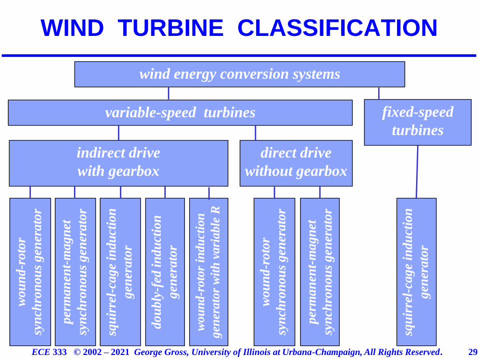
❑ The wind turbine generators or wind energy
conversion systems may be classified into two
principal categories
variable–speed rotors
fixed–speed rotors
❑ The variable–speed turbines are able advanta-
geously use the fact that wind speed varies to
WIND TURBINE GENERATORS
ECE 333 © 2002 – 2021 George Gross, University of Illinois at Urbana-Champaign, All Rights Reserved. 20
adjust the rotor speed in order to optimally match
wind speed
❑ The fixed–speed rotor generators are simpler but
do not operate at optimal efficiency; moreover, the
stresses from the rapidly varying wind speeds,
typically, require sturdier design of such turbines
WIND TURBINE GENERATORS
ECE 333 © 2002 – 2021 George Gross, University of Illinois at Urbana-Champaign, All Rights Reserved. 21
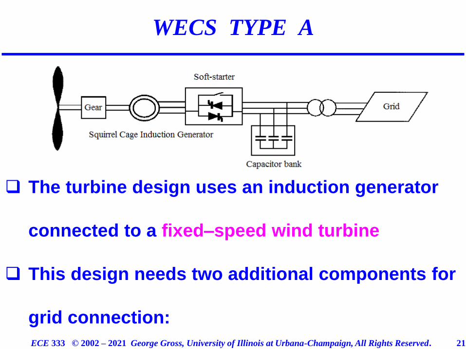
❑ The turbine design uses an induction generator
connected to a fixed–speed wind turbine
❑ This design needs two additional components for
grid connection:
WECS TYPE A
ECE 333 © 2002 – 2021 George Gross, University of Illinois at Urbana-Champaign, All Rights Reserved. 22
a soft–starter to decrease current transients
during startup phase
a capacitor bank to supply reactive power to
the generator
❑ As a result of the capacitor bank, the generator
can operate essentially as a zero-value generation
source or consumption sink of reactive power
❑ However, such capacitive compensation unable to
provide flexible reactive power control by the wind
turbine
WECS TYPE A
ECE 333 © 2002 – 2021 George Gross, University of Illinois at Urbana-Champaign, All Rights Reserved. 23
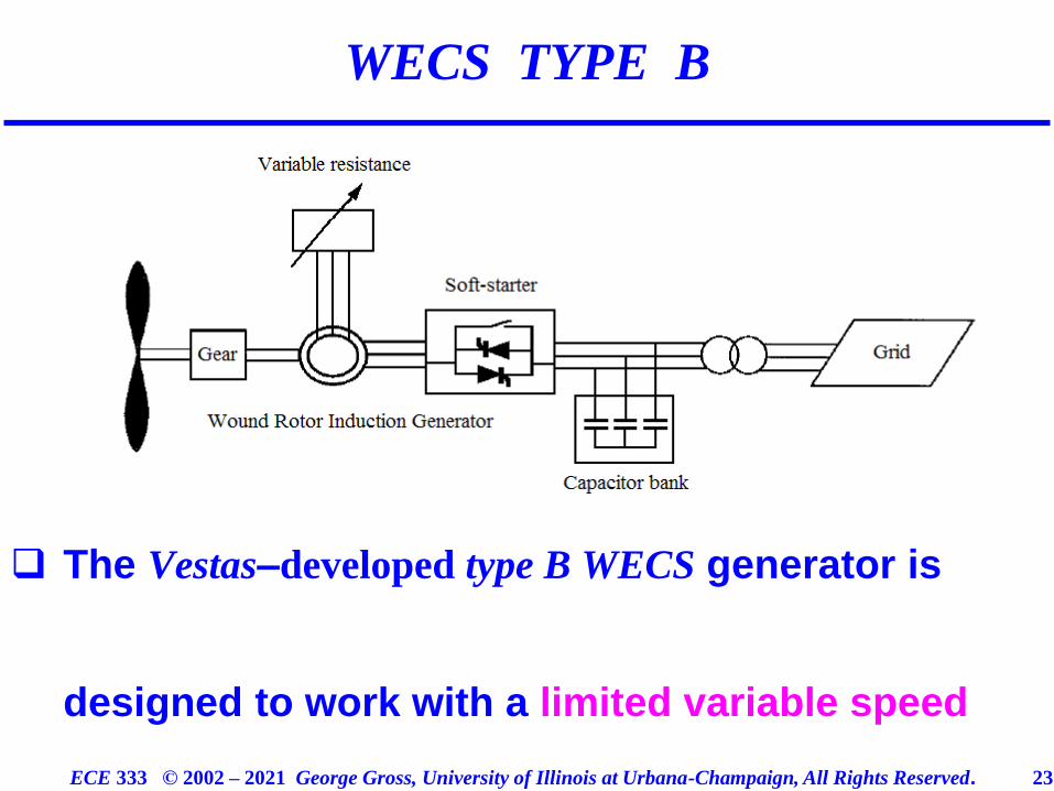
❑ The Vestas–developed type B WECS generator is
designed to work with a limited variable speed
WECS TYPE B
ECE 333 © 2002 – 2021 George Gross, University of Illinois at Urbana-Champaign, All Rights Reserved. 24
wind turbine
❑ The turbine uses the variable resistor in the rotor
to control the real power output
❑ The capacitor bank and soft–starter device roles
are analogous to those in the the type A design
WECS TYPE B
ECE 333 © 2002 – 2021 George Gross, University of Illinois at Urbana-Champaign, All Rights Reserved. 25
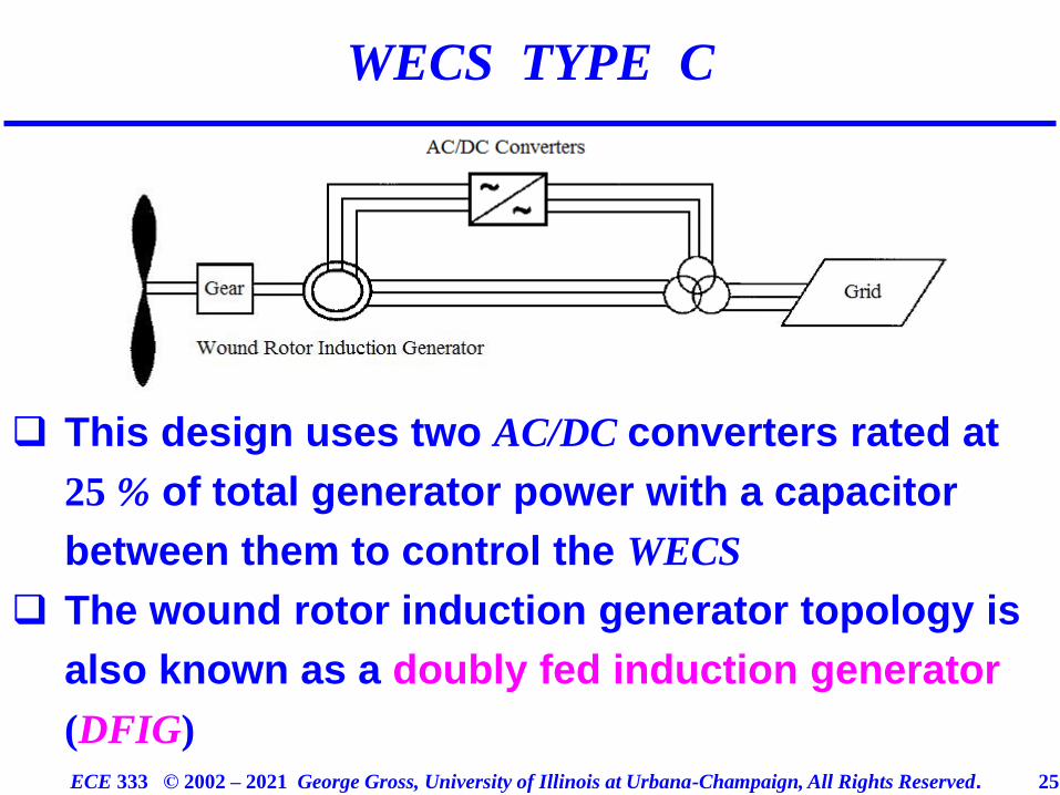
❑ This design uses two AC/DC converters rated at
25 % of total generator power with a capacitor
between them to control the WECS
❑ The wound rotor induction generator topology is
also known as a doubly fed induction generator
(DFIG)
WECS TYPE C
ECE 333 © 2002 – 2021 George Gross, University of Illinois at Urbana-Champaign, All Rights Reserved. 26
❑ The term “doubly” comes from the fact that the
generator has two electrical ports – one stator
and one rotor; unlike the squirrel cage rotor, the
DFIG has windings in the rotor, which are acces-
sible via the use of brushes and slip rings
❑ DFIGs can be controlled to provide active and
reactive power to the grid
❑ The WECS type C is the most widespread of all
wind turbines on the market
WECS TYPE C
ECE 333 © 2002 – 2021 George Gross, University of Illinois at Urbana-Champaign, All Rights Reserved. 27
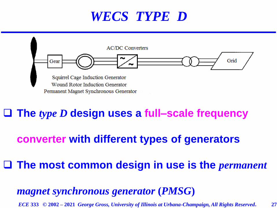
❑ The type D design uses a full–scale frequency
converter with different types of generators
❑ The most common design in use is the permanent
magnet synchronous generator (PMSG)
WECS TYPE D
ECE 333 © 2002 – 2021 George Gross, University of Illinois at Urbana-Champaign, All Rights Reserved. 28
❑ This design allows full control over the active and
the reactive power production that results in a
high-wind-energy extraction value
❑ Full power control improves power and frequency
stability in the grid and reduces the short circuit
power
❑ Most type D designs do not require a gearbox – a
distinct advantage of type D WECS
WECS TYPE D
ECE 333 © 2002 – 2021 George Gross, University of Illinois at Urbana-Champaign, All Rights Reserved. 29
WIND TURBINE CLASSIFICATION
wind energy conversion systems
variable-speed turbines fixed-speed
turbines
indirect drive
with gearbox
direct drive
without gearbox
wo
un
d-r
oto
r
syn
chro
nou
s gen
erato
r
per
ma
nen
t-m
ag
net
syn
chro
no
us
gen
era
tor
squ
irre
l-ca
ge
ind
uct
ion
gen
era
tor
do
ub
ly-f
ed i
nd
uct
ion
gen
era
tor
wou
nd
-roto
r in
du
ctio
n
gen
erato
r w
ith
vari
able
R
wo
un
d-r
oto
r
syn
chro
no
us
gen
era
tor
per
ma
nen
t-m
ag
net
syn
chro
nou
s gen
erato
r
squ
irre
l-ca
ge
ind
uct
ion
gen
era
tor