Embed Size (px)
Citation preview

B+W Wiesner.indd 1 09.11.15 17:34
Journal for Resources, Mining, Tunnelling, Geotechnics and Equipment 03 | 2015
Major projectsFehmarnbelt TunnelRenovationInnovation
Shaft constructionCoal miningChain conveyorInjections
DenmarkGermanySwitzerlandChina
GeoResources Verlag ISSN | Online 2364-8430 • Print 2364-8422 www.georesources.net
Journal

Experience trends, innovations and enthusiasm up close at the industry’s most important international exhibition. This is where the world comes together, so you can’t miss out! Prepare your business success and look forward to: 3,400 exhibitors More than half a million visitors 605,000 m² of space
The world speaks bauma.Join the conversation!
Get your ticket now:
www.bauma.de/tickets/en
31st Edition of the World’s Leading Trade Fair for Construction Machinery, Building Material Machines, Mining Machines, Construction Vehicles and Construction Equipment
www.bauma.de April 11–17, Munich
Connecting Global Competence
bauma Official
bauma16-Besucher-210x149-E.indd 1 05.10.15 12:04
GeoResources Journal 3 | 2015Content www.georesources.net
Content
4 ImprInt
A Word on
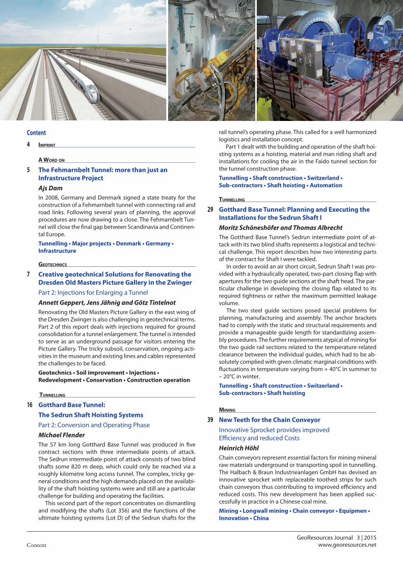
5 The Fehmarnbelt Tunnel: more than just an Infrastructure Project
Ajs DamIn 2008, Germany and Denmark signed a state treaty for the construction of a Fehmarnbelt tunnel with connecting rail and road links. Following several years of planning, the approval procedures are now drawing to a close. The Fehmarnbelt Tun-nel will close the final gap between Scandinavia and Continen-tal Europe.
Tunnelling • Major projects • Denmark • Germany • Infrastructure
GeotechnIcs
7 Creative geotechnical Solutions for Renovating the Dresden Old Masters Picture Gallery in the Zwinger
Part 2: Injections for Enlarging a Tunnel Annett Geppert, Jens Jähnig and Götz Tintelnot
Renovating the Old Masters Picture Gallery in the east wing of the Dresden Zwinger is also challenging in geotechnical terms. Part 2 of this report deals with injections required for ground consolidation for a tunnel enlargement. The tunnel is intended to serve as an underground passage for visitors entering the Picture Gallery. The tricky subsoil, conservation, ongoing acti-vities in the museum and existing lines and cables represented the challenges to be faced.
Geotechnics • Soil improvement • Injections • Redevelopment • Conservation • Construction operation
tunnellInG
16 Gotthard Base Tunnel: The Sedrun Shaft Hoisting Systems
Part 2: Conversion and Operating Phase Michael Flender
The 57 km long Gotthard Base Tunnel was produced in five contract sections with three intermediate points of attack. The Sedrun intermediate point of attack consists of two blind shafts some 820 m deep, which could only be reached via a roughly kilometre long access tunnel. The complex, tricky ge-neral conditions and the high demands placed on the availabi-lity of the shaft hoisting systems were and still are a particular challenge for building and operating the facilities.
This second part of the report concentrates on dismantling and modifying the shafts (Lot 356) and the functions of the ultimate hoisting systems (Lot D) of the Sedrun shafts for the
rail tunnel’s operating phase. This called for a well harmonized logistics and installation concept.
Part 1 dealt with the building and operation of the shaft hoi-sting systems as a hoisting, material and man riding shaft and installations for cooling the air in the Faido tunnel section for the tunnel construction phase.
Tunnelling • Shaft construction • Switzerland • Sub-contractors • Shaft hoisting • Automation
tunnellInG
29 Gotthard Base Tunnel: Planning and Executing the Installations for the Sedrun Shaft I
Moritz Schöneshöfer and Thomas AlbrechtThe Gotthard Base Tunnel’s Sedrun intermediate point of at-tack with its two blind shafts represents a logistical and techni-cal challenge. This report describes how two interesting parts of the contract for Shaft I were tackled.
In order to avoid an air short circuit, Sedrun Shaft I was pro-vided with a hydraulically operated, two-part closing flap with apertures for the two guide sections at the shaft head. The par-ticular challenge in developing the closing flap related to its required tightness or rather the maximum permitted leakage volume.
The two steel guide sections posed special problems for planning, manufacturing and assembly. The anchor brackets had to comply with the static and structural requirements and provide a manageable guide length for standardizing assem-bly procedures. The further requirements atypical of mining for the two guide rail sections related to the temperature-related clearance between the individual guides, which had to be ab-solutely complied with given climatic marginal conditions with fluctuations in temperature varying from + 40°C in summer to – 20°C in winter.
Tunnelling • Shaft construction • Switzerland • Sub-contractors • Shaft hoisting
mInInG
39 New Teeth for the Chain ConveyorInnovative Sprocket provides improved Efficiency and reduced Costs
Heinrich HöhlChain conveyors represent essential factors for mining mineral raw materials underground or transporting spoil in tunnelling. The Halbach & Braun Industrieanlagen GmbH has devised an innovative sprocket with replaceable toothed strips for such chain conveyors thus contributing to improved efficiency and reduced costs. This new development has been applied suc-cessfully in practice in a Chinese coal mine.
Mining • Longwall mining • Chain conveyor • Equipmen • Innovation • China
GeoResources Journal 3 | 2015Contentwww.georesources.net
Mining - Product Presentatio
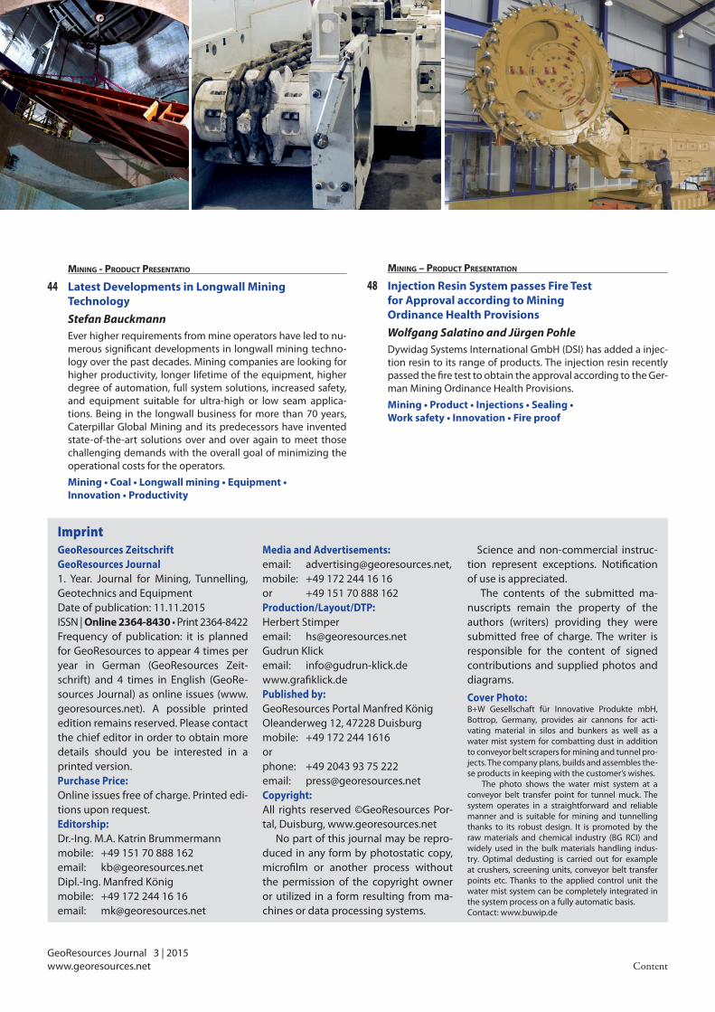
44 Latest Developments in Longwall Mining Technology
Stefan BauckmannEver higher requirements from mine operators have led to nu-merous significant developments in longwall mining techno-logy over the past decades. Mining companies are looking for higher productivity, longer lifetime of the equipment, higher degree of automation, full system solutions, increased safety, and equipment suitable for ultra-high or low seam applica-tions. Being in the longwall business for more than 70 years, Caterpillar Global Mining and its predecessors have invented state-of-the-art solutions over and over again to meet those challenging demands with the overall goal of minimizing the operational costs for the operators.
Mining • Coal • Longwall mining • Equipment • Innovation • Productivity
GeoResources Zeitschrift GeoResources Journal1. Year. Journal for Mining, Tunnelling, Geotechnics and EquipmentDate of publication: 11.11.2015ISSN | Online 2364-8430 • Print 2364-8422Frequency of publication: it is planned for GeoResources to appear 4 times per year in German (GeoResources Zeit-schrift) and 4 times in English (GeoRe-sources Journal) as online issues (www.georesources.net). A possible printed edition remains reserved. Please contact the chief editor in order to obtain more details should you be interested in a printed version.Purchase Price:Online issues free of charge. Printed edi-tions upon request.Editorship: Dr.-Ing. M.A. Katrin Brummermann mobile: +49 151 70 888 162 email: [email protected] Dipl.-Ing. Manfred Königmobile: +49 172 244 16 16 email: [email protected]
Media and Advertisements: email: [email protected], mobile: +49 172 244 16 16 or +49 151 70 888 162Production/Layout/DTP: Herbert Stimperemail: [email protected] Klickemail: [email protected] Published by:GeoResources Portal Manfred KönigOleanderweg 12, 47228 Duisburgmobile: +49 172 244 1616 or phone: +49 2043 93 75 222 email: [email protected] Copyright:All rights reserved ©GeoResources Por-tal, Duisburg, www.georesources.net
No part of this journal may be repro-duced in any form by photostatic copy, microfilm or another process without the permission of the copyright owner or utilized in a form resulting from ma-chines or data processing systems.
Science and non-commercial instruc-tion represent exceptions. Notification of use is appreciated.
The contents of the submitted ma-nuscripts remain the property of the authors (writers) providing they were submitted free of charge. The writer is responsible for the content of signed contributions and supplied photos and diagrams.
Cover Photo: B+W Gesellschaft für Innovative Produkte mbH, Bottrop, Germany, provides air cannons for acti-vating material in silos and bunkers as well as a water mist system for combatting dust in addition to conveyor belt scrapers for mining and tunnel pro-jects. The company plans, builds and assembles the-se products in keeping with the customer’s wishes.
The photo shows the water mist system at a conveyor belt transfer point for tunnel muck. The system operates in a straightforward and reliable manner and is suitable for mining and tunnelling thanks to its robust design. It is promoted by the raw materials and chemical industry (BG RCI) and widely used in the bulk materials handling indus-try. Optimal dedusting is carried out for example at crushers, screening units, conveyor belt transfer points etc. Thanks to the applied control unit the water mist system can be completely integrated in the system process on a fully automatic basis.Contact: www.buwip.de
Imprint
Mining – Product Presentation
48 Injection Resin System passes Fire Test for Approval according to Mining Ordinance Health Provisions
Wolfgang Salatino and Jürgen PohleDywidag Systems International GmbH (DSI) has added a injec-tion resin to its range of products. The injection resin recently passed the fire test to obtain the approval according to the Ger-man Mining Ordinance Health Provisions.
Mining • Product • Injections • Sealing • Work safety • Innovation • Fire proof
GeoResources Journal 3 | 2015
5 A Word on ...
The Fehmarnbelt Tunnel: more than just an Infrastructure ProjectDam:
www.georesources.net
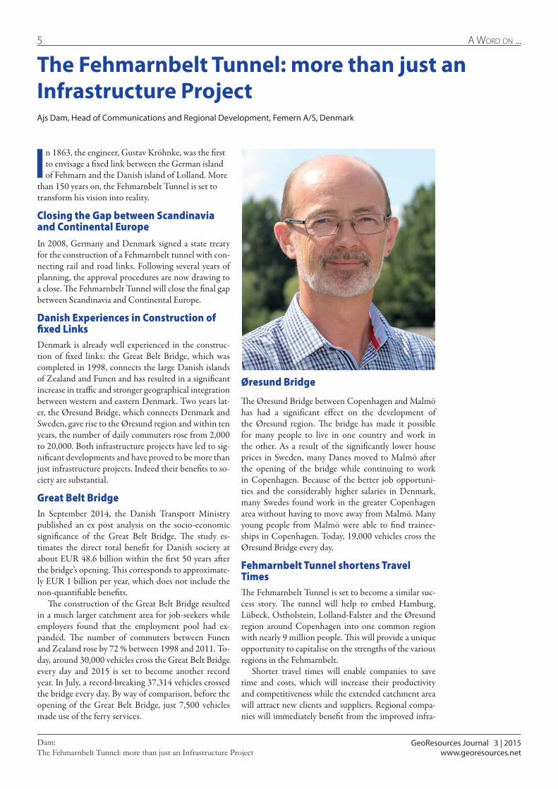
The Fehmarnbelt Tunnel: more than just an Infrastructure ProjectAjs Dam, Head of Communications and Regional Development, Femern A/S, Denmark
In 1863, the engineer, Gustav Kröhnke, was the first to envisage a fixed link between the German island of Fehmarn and the Danish island of Lolland. More
than 150 years on, the Fehmarnbelt Tunnel is set to transform his vision into reality.
Closing the Gap between Scandinavia and Continental EuropeIn 2008, Germany and Denmark signed a state treaty for the construction of a Fehmarnbelt tunnel with con-necting rail and road links. Following several years of planning, the approval procedures are now drawing to a close. The Fehmarnbelt Tunnel will close the final gap between Scandinavia and Continental Europe.
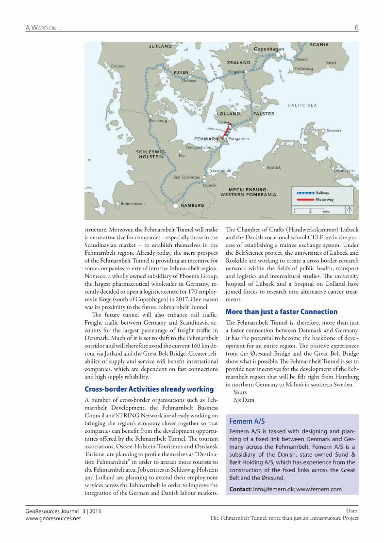
Danish Experiences in Construction of fixed LinksDenmark is already well experienced in the construc-tion of fixed links: the Great Belt Bridge, which was completed in 1998, connects the large Danish islands of Zealand and Funen and has resulted in a significant increase in traffic and stronger geographical integration between western and eastern Denmark. Two years lat-er, the Øresund Bridge, which connects Denmark and Sweden, gave rise to the Øresund region and within ten years, the number of daily commuters rose from 2,000 to 20,000. Both infrastructure projects have led to sig-nificant developments and have proved to be more than just infrastructure projects. Indeed their benefits to so-ciety are substantial.
Great Belt BridgeIn September 2014, the Danish Transport Ministry published an ex post analysis on the socio-economic significance of the Great Belt Bridge. The study es-timates the direct total benefit for Danish society at about EUR 48.6 billion within the first 50 years after the bridge’s opening. This corresponds to approximate-ly EUR 1 billion per year, which does not include the non-quantifiable benefits.
The construction of the Great Belt Bridge resulted in a much larger catchment area for job-seekers while employers found that the employment pool had ex-panded. The number of commuters between Funen and Zealand rose by 72 % between 1998 and 2011. To-day, around 30,000 vehicles cross the Great Belt Bridge every day and 2015 is set to become another record year. In July, a record-breaking 37,314 vehicles crossed the bridge every day. By way of comparison, before the opening of the Great Belt Bridge, just 7,500 vehicles made use of the ferry services.
Øresund Bridge
The Øresund Bridge between Copenhagen and Malmö has had a significant effect on the development of the Øresund region. The bridge has made it possible for many people to live in one country and work in the other. As a result of the significantly lower house prices in Sweden, many Danes moved to Malmö after the opening of the bridge while continuing to work in Copenhagen. Because of the better job opportuni-ties and the considerably higher salaries in Denmark, many Swedes found work in the greater Copenhagen area without having to move away from Malmö. Many young people from Malmö were able to find trainee-ships in Copenhagen. Today, 19,000 vehicles cross the Øresund Bridge every day.
Fehmarnbelt Tunnel shortens Travel TimesThe Fehmarnbelt Tunnel is set to become a similar suc-cess story. The tunnel will help to embed Hamburg, Lübeck, Ostholstein, Lolland-Falster and the Øresund region around Copenhagen into one common region with nearly 9 million people. This will provide a unique opportunity to capitalise on the strengths of the various regions in the Fehmarnbelt.
Shorter travel times will enable companies to save time and costs, which will increase their productivity and competitiveness while the extended catchment area will attract new clients and suppliers. Regional compa-nies will immediately benefit from the improved infra-
GeoResources Journal 3 | 2015
6A Word on ...
The Fehmarnbelt Tunnel: more than just an Infrastructure ProjectDam:
www.georesources.net
The Chamber of Crafts (Handwerkskammer) Lübeck and the Danish vocational school CELF are in the pro-cess of establishing a trainee exchange system. Under the BeltScience project, the universities of Lübeck and Roskilde are working to create a cross-border research network within the fields of public health, transport and logistics and intercultural studies. The university hospital of Lübeck and a hospital on Lolland have joined forces to research into alternative cancer treat-ments.
More than just a faster ConnectionThe Fehmarnbelt Tunnel is, therefore, more than just a faster connection between Denmark and Germany. It has the potential to become the backbone of devel-opment for an entire region. The positive experiences from the Øresund Bridge and the Great Belt Bridge show what is possible. The Fehmarnbelt Tunnel is set to provide new incentives for the development of the Feh-marnbelt region that will be felt right from Hamburg in northern Germany to Malmö in southern Sweden.
Yours Ajs Dam
Femern A/SFemern A/S is tasked with designing and plan-ning of a fixed link between Denmark and Ger-many across the Fehmarnbelt. Femern A/S is a subsidiary of the Danish, state-owned Sund & Bælt Holding A/S, which has experience from the construction of the fixed links across the Great Belt and the Øresund.
Contact: [email protected]; www.femern.com
structure. Moreover, the Fehmarnbelt Tunnel will make it more attractive for companies – especially those in the Scandinavian market – to establish themselves in the Fehmarnbelt region. Already today, the mere prospect of the Fehmarnbelt Tunnel is providing an incentive for some companies to extend into the Fehmarnbelt region. Nomeco, a wholly owned subsidiary of Phoenix Group, the largest pharmaceutical wholesaler in Germany, re-cently decided to open a logistics centre for 170 employ-ees in Køge (south of Copenhagen) in 2017. One reason was its proximity to the future Fehmarnbelt Tunnel.
The future tunnel will also enhance rail traffic. Freight traffic between Germany and Scandinavia ac-counts for the largest percentage of freight traffic in Denmark. Much of it is set to shift to the Fehmarnbelt corridor and will therefore avoid the current 160 km de-tour via Jutland and the Great Belt Bridge. Greater reli-ability of supply and service will benefit international companies, which are dependent on fast connections and high supply reliability.
Cross-border Activities already workingA number of cross-border organisations such as Feh-marnbelt Development, the Fehmarnbelt Business Council and STRING Network are already working on bringing the region’s economy closer together so that companies can benefit from the development opportu-nities offered by the Fehmarnbelt Tunnel. The tourism associations, Ostsee-Holstein-Tourismus and Østdansk Turisme, are planning to profile themselves as “Destina-tion Fehmarnbelt” in order to attract more tourists to the Fehmarnbelt area. Job centres in Schleswig-Holstein and Lolland are planning to extend their employment services across the Fehmarnbelt in order to improve the integration of the German and Danish labour markets.
GeoResources Journal 3 | 2015
7 Geotechnics
Dresden Old Masters Picture Gallery in the Zwinger – Part 2: Injections for Enlarging a TunnelGeppert, Jähnig and Tintelnot:
www.georesources.net
Creative geotechnical Solutions for Renovating the Dresden Old Masters Picture Gallery in the ZwingerPart 2: Injections for Enlarging a Tunnel
Dipl.-Geol. Annett Geppert and Dipl.-Ing (FH) Jens Jähnig, Jähnig GmbH, Dorfhain, GermanyGötz Tintelnot, TPH Bausysteme GmbH, Norderstedt, Germany
General
As previously described in Part 1 of this report [1, 2] the Jähnig GmbH located in the Dresden region was commissioned to redevelop the Old Masters Picture Gallery in the east wing of the Semperbau at the Dres-den Zwinger. Part 1 contains general information re-lating to the state-owned Sächsische Immobilien- und Baumanagement (SIB) renovation project carried out in conjunction with the State Art Collections Dresden and explains how a piling foundation for a new freight elevator was produced.
This second part of the report concentrates on injec-tions designed to consolidate the ground for enlarging a tunnel. In the Old Masters Picture Gallery’s new ex-hibition concept the tunnel is integrated in the exhibi-tion serving as an underground passage for visitors.
Firstly the general conditions for enlarging the tun-nel are explained along with the ground situation and the approach applied. The main part of the report deals with general pointers for selecting the injection method to consolidate the soil, determining the grout-ing concept for enlarging the tunnel in the Zwinger, trial injections undertaken on the spot and how grout-ing was executed. This part of the report concludes with a summary.
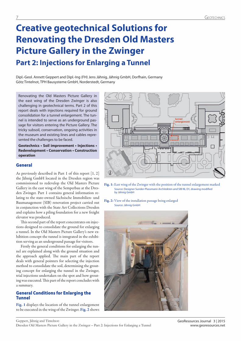
General Conditions for Enlarging the TunnelFig. 1 displays the location of the tunnel enlargement to be executed in the wing of the Zwinger. Fig. 2 shows
Renovating the Old Masters Picture Gallery in the east wing of the Dresden Zwinger is also challenging in geotechnical terms. Part 2 of this report deals with injections required for ground consolidation for a tunnel enlargement. The tun-nel is intended to serve as an underground pas-sage for visitors entering the Picture Gallery. The tricky subsoil, conservation, ongoing activities in the museum and existing lines and cables repre-sented the challenges to be faced.
Geotechnics • Soil improvement • Injections • Redevelopment • Conservation • Construction operation
Fig. 2: View of the installation passage being enlarged Source: Jähnig GmbH
Fig. 1: East wing of the Zwinger with the position of the tunnel enlargement marked Source: Designer Sunder-Plassmann Architekten and SIB NL D1, drawing modified by Jähnig GmbH
GeoResources Journal 3 | 2015
8Geotechnics
Dresden Old Masters Picture Gallery in the Zwinger – Part 2: Injections for Enlarging a TunnelGeppert, Jähnig and Tintelnot:
www.georesources.net
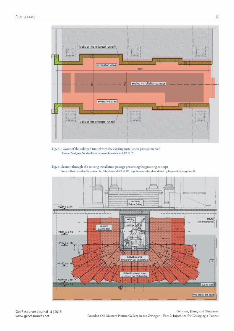
Fig. 3: Layout of the enlarged tunnel with the existing installation passage marked Source: Designer Sunder-Plassmann Architekten and SIB NL D1
Fig. 4: Section through the existing installation passage presenting the grouting concept Source: Basic Sunder-Plassmann Architekten and SIB NL D1, supplemented and modified by Geppert, Jähnig GmbH
9 Geotechnics
the narrow installation passage to be enlarged, in other words, the initial status. The constricted working area in the narrow passage was further restricted by cables and a heating duct, which could not simply be removed on account of ongoing activities at the museum. The basic diagram of the enlargement area in Fig. 3 indi-cates that the clear passage width amounting to al-most 1.50 m of the 11 m long passage was expanded practically threefold. In addition, the clear height was increased by more than one metre as shown in the sec-tion in Fig. 4. Fig. 4 also indicates that the tunnel runs directly beneath the vestibule, i. e. the Picture Gallery’s entrance zone – with a high frequency of visitors. Dur-ing the entire conversion process the intention was to ensure that the museum could continue to operate without any disturbances via the installation passage. As a result, the enlargement could only be completed by trenchless means.
Ground Situation and applied SolutionThe required ground investigation was carried out by the Baugrund Dresden Ingenieurgesellschaft mbH un-der highly constricted space conditions from the exist-ing installation passage. Exploratory drilling that was originally planned below the vestibule could not be
executed as there was not sufficient knowledge available pertaining to the status of the lines and cables.
Two vertical and one horizontal percussion drill holes as well as a dynamic probe were executed. As shown in Fig. 4 a largely loosely to medium-densely bedded fill was encountered directly beneath the cellar floor as well as to the side of the installation passage with an average thickness of 2 m. River gravels and sands were located underneath a 30 cm thick intermediate layer of swamp loam.
Investigation of the composition and properties of the ground layers revealed that the statically relevant fill was not sufficiently stable for a vertical excavation. As a result, soil stabilisation was resorted to for the trenchless excavation and reduced the amount of shoring and sup-port measures at the face and walls. An independently supporting body of soil was to be created by grouting. The location and dimensions are provided in Fig. 4.
Grouting Method and Soil StabilisationDuring grouting an injection agent is installed in the pores of the soil or in the cracks of the rock. By means of chemical reaction or physical change of state the in-jection agent hardens after the grouting process thus retaining its shape and position. The grouting method,
TPH.waterproofi ng systems
Joint sealing Injection technology Restoration Protection Tunneling
Polymer Stabilizing Geological injection (PSGi)
Complete sealing systems for tunneling
Reliable systems for stopping of water inrush
TPH Bausysteme GmbH | Nordportbogen 8 | D - 22848 Norderstedt | Tel. + 49 (0) 40 / 52 90 66 78-0 | www.tph-bausysteme.com

GeoResources Journal 3 | 2015
10Geotechnics
Dresden Old Masters Picture Gallery in the Zwinger – Part 2: Injections for Enlarging a TunnelGeppert, Jähnig and Tintelnot:
www.georesources.net
ter and cannot set. In addition, the mortar would cause further water to access the ground, something that is critical in the event of heaving soils.
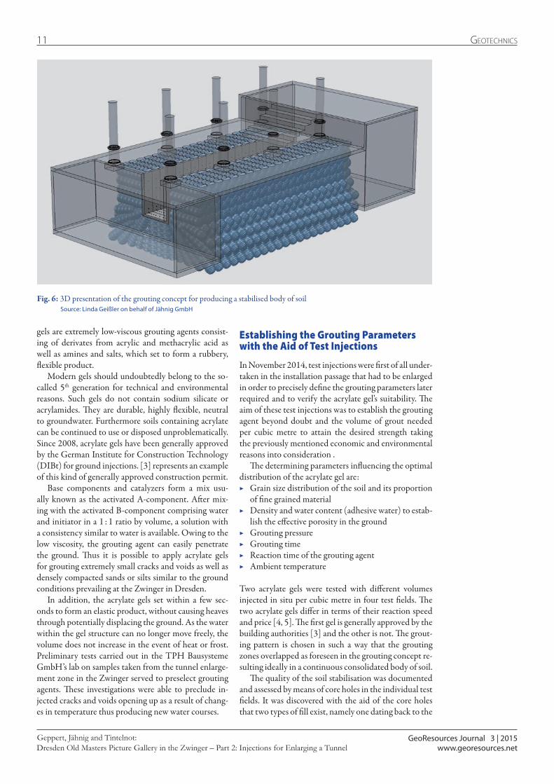
Grouting ConceptThe grouting concept was devised jointly by the Jähnig GmbH as contractor and a special company for grout-ing technology, which manufactures its own grouting agents and equipment. In the process, the client’s wishes were taken into account. First of all, an effort was made to create a body of soil with the required strengths of 4 N/mm² for the tunnel enlargement in the Zwinger. The geometry and dimensions are shown in Figs. 4 and 6. Given the state of the prevailing ground the gap be-tween injecting ports was set at 60 cm. The layers were staggered to overlap one another horizontally so that the individual injection zones were interlocked.
Furthermore the concept foresaw the option of dif-ferentiating the strengths attained for economic as well as ecological reasons. Thus for instance in the excava-tion area a reduced strength, tailing off to roughly half of the scheduled 4 N/mm² strength value was required for creating a stable trench wall, which allowed the complete tunnel height to be excavated without restric-tion. As this meant the volume of the grouting agent could be reduced, costs could also be lowered. In addi-tion, the lower strength also facilitated the subsequent demolition work.
The application of acrylate gels as grouting agent was possible for stabilising the soil in this project. Acrylate
Fig. 5: Application possibilities for grouting agents depending on the permeability of the prevailing soil Source: TPH Bausysteme GmbH
the grouting pressure and the grouting agent must be chosen in keeping with the purpose, the geological, physical and chemical properties of the ground, the wa-ter conditions and other relevant general conditions. It is essential that aspects of a technical nature relating to the grouting process are considered at an early stage of planning.
The main purpose of the injections for enlarging the tunnel in the Zwinger was soil stabilisation. However, a waterproofing effect was also achieved.
During jet grouting, a cement-based liquid injection agent is applied to the ground at extreme pressure of up to 800 bar. Such high pressures can cause heaves affect-ing the ground, which had to be avoided at all costs in the historic Zwinger building and in the direct vicin-ity of ongoing museum operations. Consequently, low pump pressures for the injection process made sense.
Many aspects have to be considered when selecting the grouting agent. Extensive experience and knowledge are imperative for assessing the interaction between the ground and grouting agent. It generally applies that the more finely grained and compact the soft ground is and the lower its permeability, the more limited the choice of suitable grouting agents will be. Fig. 5 displays the range of application for various grouting agents depend-ing on the soil’s permeability. Furthermore, the water conditions exert a substantial influence on the choice of grouting agent. Thus cement mortars cannot be applied if the soil is affected by a strong flow of current as the injected cement emulsion is dissolved by the groundwa-
GeoResources Journal 3 | 2015
11 Geotechnics
Dresden Old Masters Picture Gallery in the Zwinger – Part 2: Injections for Enlarging a TunnelGeppert, Jähnig and Tintelnot:
www.georesources.net
gels are extremely low-viscous grouting agents consist-ing of derivates from acrylic and methacrylic acid as well as amines and salts, which set to form a rubbery, flexible product.
Modern gels should undoubtedly belong to the so-called 5th generation for technical and environmental reasons. Such gels do not contain sodium silicate or acrylamides. They are durable, highly flexible, neutral to groundwater. Furthermore soils containing acrylate can be continued to use or disposed unproblematically. Since 2008, acrylate gels have been generally approved by the German Institute for Construction Technology (DIBt) for ground injections. [3] represents an example of this kind of generally approved construction permit.
Base components and catalyzers form a mix usu-ally known as the activated A-component. After mix-ing with the activated B-component comprising water and initiator in a 1 : 1 ratio by volume, a solution with a consistency similar to water is available. Owing to the low viscosity, the grouting agent can easily penetrate the ground. Thus it is possible to apply acrylate gels for grouting extremely small cracks and voids as well as densely compacted sands or silts similar to the ground conditions prevailing at the Zwinger in Dresden.
In addition, the acrylate gels set within a few sec-onds to form an elastic product, without causing heaves through potentially displacing the ground. As the water within the gel structure can no longer move freely, the volume does not increase in the event of heat or frost. Preliminary tests carried out in the TPH Bausysteme GmbH’s lab on samples taken from the tunnel enlarge-ment zone in the Zwinger served to preselect grouting agents. These investigations were able to preclude in-jected cracks and voids opening up as a result of chang-es in temperature thus producing new water courses.
Fig. 6: 3D presentation of the grouting concept for producing a stabilised body of soil Source: Linda Geißler on behalf of Jähnig GmbH
Establishing the Grouting Parameters with the Aid of Test Injections
In November 2014, test injections were first of all under-taken in the installation passage that had to be enlarged in order to precisely define the grouting parameters later required and to verify the acrylate gel’s suitability. The aim of these test injections was to establish the grouting agent beyond doubt and the volume of grout needed per cubic metre to attain the desired strength taking the previously mentioned economic and environmental reasons into consideration .
The determining parameters influencing the optimal distribution of the acrylate gel are:
▶ Grain size distribution of the soil and its proportion of fine grained material
▶ Density and water content (adhesive water) to estab-lish the effective porosity in the ground
▶ Grouting pressure ▶ Grouting time ▶ Reaction time of the grouting agent ▶ Ambient temperature
Two acrylate gels were tested with different volumes injected in situ per cubic metre in four test fields. The two acrylate gels differ in terms of their reaction speed and price [4, 5]. The first gel is generally approved by the building authorities [3] and the other is not. The grout-ing pattern is chosen in such a way that the grouting zones overlapped as foreseen in the grouting concept re-sulting ideally in a continuous consolidated body of soil.
The quality of the soil stabilisation was documented and assessed by means of core holes in the individual test fields. It was discovered with the aid of the core holes that two types of fill exist, namely one dating back to the
GeoResources Journal 3 | 2015
12Geotechnics
Dresden Old Masters Picture Gallery in the Zwinger – Part 2: Injections for Enlarging a TunnelGeppert, Jähnig and Tintelnot:
www.georesources.net
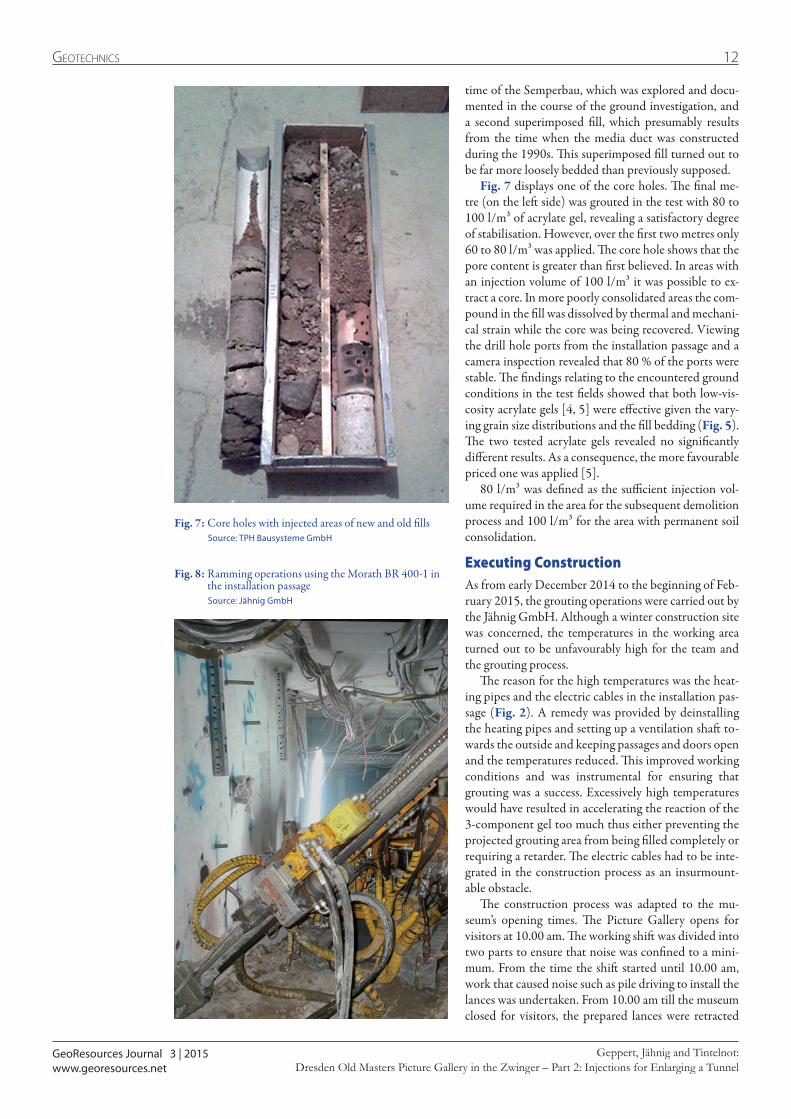
time of the Semperbau, which was explored and docu-mented in the course of the ground investigation, and a second superimposed fill, which presumably results from the time when the media duct was constructed during the 1990s. This superimposed fill turned out to be far more loosely bedded than previously supposed.
Fig. 7 displays one of the core holes. The final me-tre (on the left side) was grouted in the test with 80 to 100 l/m³ of acrylate gel, revealing a satisfactory degree of stabilisation. However, over the first two metres only 60 to 80 l/m³ was applied. The core hole shows that the pore content is greater than first believed. In areas with an injection volume of 100 l/m³ it was possible to ex-tract a core. In more poorly consolidated areas the com-pound in the fill was dissolved by thermal and mechani-cal strain while the core was being recovered. Viewing the drill hole ports from the installation passage and a camera inspection revealed that 80 % of the ports were stable. The findings relating to the encountered ground conditions in the test fields showed that both low-vis-cosity acrylate gels [4, 5] were effective given the vary-ing grain size distributions and the fill bedding (Fig. 5). The two tested acrylate gels revealed no significantly different results. As a consequence, the more favourable priced one was applied [5].
80 l/m³ was defined as the sufficient injection vol-ume required in the area for the subsequent demolition process and 100 l/m³ for the area with permanent soil consolidation.
Executing ConstructionAs from early December 2014 to the beginning of Feb-ruary 2015, the grouting operations were carried out by the Jähnig GmbH. Although a winter construction site was concerned, the temperatures in the working area turned out to be unfavourably high for the team and the grouting process.
The reason for the high temperatures was the heat-ing pipes and the electric cables in the installation pas-sage (Fig. 2). A remedy was provided by deinstalling the heating pipes and setting up a ventilation shaft to-wards the outside and keeping passages and doors open and the temperatures reduced. This improved working conditions and was instrumental for ensuring that grouting was a success. Excessively high temperatures would have resulted in accelerating the reaction of the 3-component gel too much thus either preventing the projected grouting area from being filled completely or requiring a retarder. The electric cables had to be inte-grated in the construction process as an insurmount-able obstacle.
The construction process was adapted to the mu-seum’s opening times. The Picture Gallery opens for visitors at 10.00 am. The working shift was divided into two parts to ensure that noise was confined to a mini-mum. From the time the shift started until 10.00 am, work that caused noise such as pile driving to install the lances was undertaken. From 10.00 am till the museum closed for visitors, the prepared lances were retracted
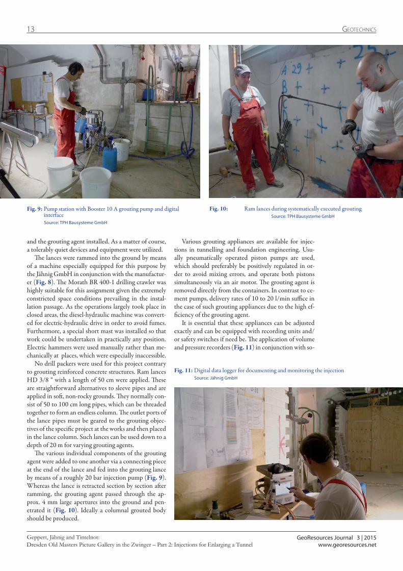
Fig. 8: Ramming operations using the Morath BR 400-1 in the installation passage
Source: Jähnig GmbH
Fig. 7: Core holes with injected areas of new and old fills Source: TPH Bausysteme GmbH
GeoResources Journal 3 | 2015
13 Geotechnics
Dresden Old Masters Picture Gallery in the Zwinger – Part 2: Injections for Enlarging a TunnelGeppert, Jähnig and Tintelnot:
www.georesources.net
Fig. 9: Pump station with Booster 10 A grouting pump and digital interface
Source: TPH Bausysteme GmbH
Fig. 10: Ram lances during systematically executed grouting Source: TPH Bausysteme GmbH
and the grouting agent installed. As a matter of course, a tolerably quiet devices and equipment were utilized.
The lances were rammed into the ground by means of a machine especially equipped for this purpose by the Jähnig GmbH in conjunction with the manufactur-er (Fig. 8). The Morath BR 400-1 drilling crawler was highly suitable for this assignment given the extremely constricted space conditions prevailing in the instal-lation passage. As the operations largely took place in closed areas, the diesel-hydraulic machine was convert-ed for electric-hydraulic drive in order to avoid fumes. Furthermore, a special short mast was installed so that work could be undertaken in practically any position. Electric hammers were used manually rather than me-chanically at places, which were especially inaccessible.
No drill packers were used for this project contrary to grouting reinforced concrete structures. Ram lances HD 3/8 “ with a length of 50 cm were applied. These are straightforward alternatives to sleeve pipes and are applied in soft, non-rocky grounds. They normally con-sist of 50 to 100 cm long pipes, which can be threaded together to form an endless column. The outlet ports of the lance pipes must be geared to the grouting objec-tives of the specific project at the works and then placed in the lance column. Such lances can be used down to a depth of 20 m for varying grouting agents.
The various individual components of the grouting agent were added to one another via a connecting piece at the end of the lance and fed into the grouting lance by means of a roughly 20 bar injection pump (Fig. 9). Whereas the lance is retracted section by section after ramming, the grouting agent passed through the ap-prox. 4 mm large apertures into the ground and pen-etrated it (Fig. 10). Ideally a columnal grouted body should be produced.
Fig. 11: Digital data logger for documenting and monitoring the injection Source: Jähnig GmbH
Various grouting appliances are available for injec-tions in tunnelling and foundation engineering. Usu-ally pneumatically operated piston pumps are used, which should preferably be positively regulated in or-der to avoid mixing errors, and operate both pistons simultaneously via an air motor. The grouting agent is removed directly from the containers. In contrast to ce-ment pumps, delivery rates of 10 to 20 l/min suffice in the case of such grouting appliances due to the high ef-ficiency of the grouting agent.
It is essential that these appliances can be adjusted exactly and can be equipped with recording units and/or safety switches if need be. The application of volume and pressure recorders (Fig. 11) in conjunction with so-

GeoResources Journal 3 | 2015
14Geotechnics
Dresden Old Masters Picture Gallery in the Zwinger – Part 2: Injections for Enlarging a TunnelGeppert, Jähnig and Tintelnot:
www.georesources.net
this way, effective decisions were taken in spite of the prevailing critical soil conditions and the sensitive framework criteria resulting from conservation and on-going museum operation. The demands of a technical, ecological, economic and construction operational na-ture that were posed, were thus fulfilled. The strived for strengths were attained and manual demolition for the tunnel enlargement still remained an option.
After grouting was completed, the trenchless excava-tion commenced in February 2015, which is the subject of Part 3 of this report.
References Geppert, A.; Jähnig, J.; Tintelnot, G.: Kreative Geo-
technische Lösungen für die Sanierung der Dresdner Gemäldegalerie Alte Meister im Zwinger – Teil 2: In-jektionen für eine Tunnelerweiterung. GeoResources Zeitschrift, 2 | 2015, S. 7 - 15
[1] Jähnig, J.; Geppert, A.: Kreative Geo technische Lösun-gen für die Sanierung der Dresdner Gemäldegalerie Alte Meister im Zwinger – Teil 1: Gründung eines neuen Las-tenaufzugs. GeoResources Zeitschrift, 1 | 2015, S. 9 - 13
[2] Jähnig, J.; Geppert, A.: Creative geotechnical Solutions for Renovatin the Dresden Old Masters Picture Gellery in the Zwinger – Part 1: Foundation for an nes Freight Elvator. GeoResources Journal 2 | 2015, S. 9 - 13
[3] Deutsches Institut für Bautechnik (DIBt): Allge-meine bauaufsichtliche Zulassung für Hydrogel “RUB-BERTITE” als Schleierinjektion. Zulassungsnummer Z-101.29-3, Geltungsdauer vom 1. Januar 2014 bis zum 1. Januar 2019
[4] TPH Bausysteme GmbH: Technisches Datenblatt für RUBBERTITE für Schleierinjektion. Stand 26.03.2014.
[5] TPH Bausysteme GmbH: Technisches Datenblatt für ECOCRYL. Stand 17.03.2014.
Fig. 12: Ground saturated with acrylate gel Source: Jähnig GmbH
phisticated grouting assignments is most advisable by means of which limits can be set and so-called unma-nipulatable abort criteria can be prescribed by means of separate software and corresponding storage technique (e. g. SD card). The soil characteristic values previously determined and general conditions, the selected grout-ing programme and the planners’ specifications repre-sent the basis for the values.
A team of on average three to four persons worked first of all on day shifts and later on during the night as well to produce the stabilised bodies of soil shown in Figs. 4 and 6. Thanks to the grouting concept that was previously described as many as 30 lances up to 4 m in length were installed per shift. Altogether, around 20,000 litres of acrylate gel was injected and a consoli-dated body of soil with a volume of roughly 225 m³ cre-ated. Around the half of the body of soil was located in the subsequent demolition area and was grouted using the lower grouting agent volume of 80 l/m³. In this way, altogether roughly more than 10 % grouting agent as well as its transportation into the tricky to ac-cess installation passage was saved. Furthermore, subse-quent extraction was facilitated on account of the lower strength.
SummarySoil stabilisation represented an essential and important measure to carry out the tunnel enlargement for the un-derground museum passage. Fig. 12 shows the areas grouted with acrylate gel with the successful injection process identified in blue.
The grouting concept was chosen and the grouting parameters established based on the experience of the responsible contractor and the special company for grouting technology as well as the test field results. In

GeoResources Journal 3 | 2015
15 Geotechnics
Dresden Old Masters Picture Gallery in the Zwinger – Part 2: Injections for Enlarging a TunnelGeppert, Jähnig and Tintelnot:
www.georesources.net
Dipl.-Geol. Annett GeppertAfter qualifying as a draftswoman specializing in road construction, foun-dation engineering and landscaping, she studied geology/paleontology at the TU Bergakademie Freiberg concentrat-ing on geotechnics/engineering geology. During her period of study, a close association with the Jähnig GmbH evolved.Since gaining her diploma as geologist and Master of Science, she has worked for the Jähnig GmbH and has established herself in marketing in addition to geology and geotechnics.
Contact: [email protected]
Dipl.-Ing. (FH) Jens Jähnigstudied in Cottbus at the School of Civil En-gineering and gained his degree in 1990. He has specialized rock and soil stabilization ever since. After a short phase as construction manager for the Felssicherung Königl Company, he founded the firm of Jens Jähnig Felssicherung in 1992. He has functioned as managing director of the Jähnig GmbH since 1996. Thanks to his innovative ideas and visions the company is thriving.The company specializes in drill process tech-nology in various types of soil, rock and slope supporting by means of protective netting against rockfalls, safety fences and shotcrete as well as foundations and upgrading foundations of structures.
Contact: [email protected]
Götz Tintelnotis the CEO of TPH Bausysteme GmbH.The TPH Bausysteme GmbH has been one of the leading compa-nies in the world for grouting and water-proofing technology for all of 50 years. It can look back on ex-perience from projects in some 50 countries, responds to innovations and is thus involved intensively in the further development of grouting agents and methods.
Contact: [email protected]

GeoResources Journal 3 | 2015
16Tunnelling
Gotthard Base Tunnel: The Sedrun Shaft Hoisting Systems – Part 2: Conversion and Operating PhaseFlender:
www.georesources.net
Gotthard Base Tunnel:The Sedrun Shaft Hoisting SystemsPart 2: Conversion and Operating PhaseMichael Flender, Siemag Tecberg GmbH, Haiger, Germany
1 IntroductionAfter dealing with the tunnel construction phase in Part 1 of the report [1, 2], Part 2 examines the concept and functions of the new, ultimate hoisting systems for the Sedrun shafts (Lot D). Towards this end, the dis-
The 57 km long Gotthard Base Tunnel was pro-duced in five contract sections with three inter-mediate points of attack. The Sedrun intermedi-ate point of attack consists of two blind shafts some 820 m deep, which could only be reached via a roughly kilometre long access tunnel. The complex, tricky general conditions and the high demands placed on the availability of the shaft hoisting systems were and still are a particular challenge for building and operating the facilities.
This second part of the report concentrates on dismantling and modifying the shafts (Lot 356) and the functions of the ultimate hoisting systems (Lot D) of the Sedrun shafts for the rail tunnel’s operating phase. This called for a well harmonized logistics and installation concept.
Part 1 dealt with the building and operation of the shaft hoisting systems as a hoisting, material and man riding shaft and installations for cooling the air in the Faido tunnel section for the tunnel construction phase.
Tunnelling • Shaft construction • Switzerland • Sub-contractors • Shaft hoisting • Automation
Fig. 1: Shaft hoisting systems in Shaft I at Sedrun for the GBT operating phase Source: Siemag Tecberg GmbH, unless indicated otherwise
mantling technology (Lot 356) as well as modifying the shaft hoisting facilities will be dealt with. The com-plex and tricky general conditions posed by the major Sedrun construction site called for well harmonized logistics and installation concept during the conversion phase, which e. g. also had to take into consideration roads kept free of snow for heavy transports. Assurance of high availability for the shaft hoisting facilities being dismantled as well as their replacements represented the determining factors.
2 Classifying the Sedrun Shafts in the GBT Project
Shaft I in Sedrun was described as the tunnel’s “lifeline” during the entire construction phase of the GBT. After all the ultimate success of how construction progressed in the Sedrun part-section actually depended on the shaft hoisting systems in Shaft I. Consequently Shaft I exercised a major influence on the overall scheduling process for producing the GBT. Shaft I also took over a key function in the final phase as the GBT was prepared for to become operational – especially when the tun-nel opening was brought forward from 2017 to 2016 so that all buffer times were eliminated and a strict time-

GeoResources Journal 3 | 2015
17 Tunnelling
Gotthard Base Tunnel: The Sedrun Shaft Hoisting Systems – Part 2: Conversion and Operating PhaseFlender:
www.georesources.net
table for modifying the shaft hoisting systems by spring 2014 had to be adhered to.
The ultimate hoisting systems for the two Sedrun shafts provide for inspection, maintenance and the servicing of the installations located in the shafts dur-ing the GBT rail operating phase. The power and data cables in the shaft for supplying the tunnel tubes in general at the shaft head and a water pressure line to provide a constant supply of water at the bottom of the shaft deserve particular mention here. The new Lot D shaft hoisting facilities shown in Fig. 1 were mainly produced for inspecting Shaft I and further systems such as the supply lines and devised for assembling and replacing cables. However, manriding right to the shaft bottom is also possible so that service staff can be trans-ported. In future, shaft inspections are undertaken by means of a circular inspection platform (IPF) weighing 15 t running on steel guides, which can be operated in Shaft I with a 2 x 560 kW rated 2-rope hoist (IPF winch) at up to 4 m/s. The IPF’s payload amounts to 5 t. A 400 kW shaft hoist, the so-called cable support-ing winch (CS winch), was installed to ensure that ca-bles could be assembled safely and efficiently. The CS winch’s payload amounts to some 15.5 t.
Manriding and inspection of the Shaft II is carried out with an inspection cage, which is operated in the shaft via the mobile shaft winch. The upcast Shaft II was closed with a demountable shaft cover to extract the op-erating ventilation air.
Siemag Tecberg found itself repeatedly faced with enormous challenges in developing and planning the execution of the systems with regard to production, as-sembly and operation, which required special designs as a result of the unalterable general conditions and the changing requirements encountered during the con-struction phase of this extremely large construction site.
Measures to avoid errors, outfalls and impermissible risks of damage were resorted to during planning and development of the new hoisting systems for Lot D. The RAMS process providing a systematic approach and analysis devised for rail systems was applied to ca-ter for the required availability and safety goals for the shaft hoisting systems. RAMS stands for Reliability, Availability, Maintenance and Safety. The RAMS anal-ysis relates to the entire electromechanical installations for the new shaft hoisting systems, such as for example, the electric switch cabinets, transformers and hoisting machines.
The fact that practically all transports to the shaft head, to the shafts and to the bottom of the shaft had to be undertaken via the 1 km long access tunnel in Se-drun was for instance, of decisive logistical and struc-tural significance. As the access tunnel also had to be modified, temporary closures had to be included when planning the schedule to avoid mutual obstructions and standstills on the construction site.
The concepts for the resources and special designs were developed and built in close collaboration with the AlpTransit Gotthard AG and the Ingenieurgemein-
schaft Gotthard-Basistunnel Süd (IG GBTS). Well-es-tablished and viable relations as well as close and ongo-ing coordination were essential with the client, the IG GBTS, the Transco Sedrun JV, the Deutsche Montan Technologie GmbH (DMT) and especially the respon-sible sub-contractors.
3 Conversion Phase for the Shaft Hoisting Systems and Construction Activities in Shaft I
In addition to dismantling the existing shaft hoist-ing systems in Lot 356 and setting up the Lot D shaft hoisting systems, all other machines located in the shaft and installations from other contract sections had to be dismantled and replaced. The necessary dismantling and assembly activities as well as the required construc-tion work in and around the shaft were undertaken in conjunction with various contract sections. However, these operations were always coordinated and accompa-nied through Siemag Tecberg’s own operating staff. The company deployed around 20 shaft-experienced mem-bers of staff for dismantling, assembly and starting up operations.
The basic requirement for carrying out all activities in Shaft I was an approved and operational rescue con-cept for all phases of disassembly and assembly. The main conversion phases and the application of the shaft hoist-ing systems in Lots 356 and D are described as follows.
3.1 Dismantling Phase in Lot 356 and Construction Work in Shaft I
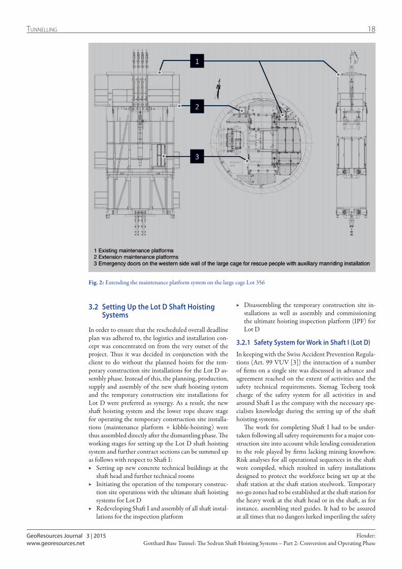
In November 2011, the Siemag Tecberg was commis-sioned by the Transco Sedrun JV to supply new, fold-out working stages for the existing large cage (Fig. 2) for the forthcoming disassembly and assembly operations. The existing maintenance platform system on the large cage was extended and started operating in May 2012. Extra fold-out working stages were also added to the central floor and the base frame for concreting opera-tions. In this way, a maintenance platform system with relocatable and extendable working stages as well as cor-responding detachable handrails and protective roof structures was available. Thanks to this inspection plat-form system it was possible to undertake the following operations in the various shaft sectors safely:
▶ Disassembly and backfilling of the shaft sump ▶ Disassembly of the shaft installations and backfilling
of the pump chambers and water reservoir in the shaft ▶ Disassembling the hoisting facilities at the shaft sta-
tion ▶ Setting up the new shaft station steelwork and the
new concrete in the MFS at the shaft bottom ▶ Disassembling the head frame and hoisting systems,
the rope sheave station and API pipelines at the shaft head
The shaft hoisting systems and all shaft installations from Lot 356 were decommissioned in 2012 and dis-mantled by the end of 2013.
GeoResources Journal 3 | 2015
18Tunnelling
Gotthard Base Tunnel: The Sedrun Shaft Hoisting Systems – Part 2: Conversion and Operating PhaseFlender:
www.georesources.net
3.2 Setting Up the Lot D Shaft Hoisting Systems
In order to ensure that the rescheduled overall deadline plan was adhered to, the logistics and installation con-cept was concentrated on from the very outset of the project. Thus it was decided in conjunction with the client to do without the planned hoists for the tem-porary construction site installations for the Lot D as-sembly phase. Instead of this, the planning, production, supply and assembly of the new shaft hoisting system and the temporary construction site installations for Lot D were preferred as synergy. As a result, the new shaft hoisting system and the lower rope sheave stage for operating the temporary construction site installa-tions (maintenance platform + kibble-hoisting) were thus assembled directly after the dismantling phase. The working stages for setting up the Lot D shaft hoisting system and further contract sections can be summed up as follows with respect to Shaft I:
▶ Setting up new concrete technical buildings at the shaft head and further technical rooms
▶ Initiating the operation of the temporary construc-tion site operations with the ultimate shaft hoisting systems for Lot D
▶ Redeveloping Shaft I and assembly of all shaft instal-lations for the inspection platform
▶ Disassembling the temporary construction site in-stallations as well as assembly and commissioning the ultimate hoisting inspection platform (IPF) for Lot D
3.2.1 Safety System for Work in Shaft I (Lot D)
In keeping with the Swiss Accident Prevention Regula-tions (Art. 99 VUV [3]) the interaction of a number of firms on a single site was discussed in advance and agreement reached on the extent of activities and the safety technical requirements. Siemag Tecberg took charge of the safety system for all activities in and around Shaft I as the company with the necessary spe-cialists knowledge during the setting up of the shaft hoisting systems.
The work for completing Shaft I had to be under-taken following all safety requirements for a major con-struction site into account while lending consideration to the role played by firms lacking mining knowhow. Risk analyses for all operational sequences in the shaft were compiled, which resulted in safety installations designed to protect the workforce being set up at the shaft station at the shaft station steelwork. Temporary no-go zones had to be established at the shaft station for the heavy work at the shaft head or in the shaft, as for instance, assembling steel guides. It had to be assured at all times that no dangers lurked imperiling the safety
Fig. 2: Extending the maintenance platform system on the large cage Lot 356
GeoResources Journal 3 | 2015
19 Tunnelling
Gotthard Base Tunnel: The Sedrun Shaft Hoisting Systems – Part 2: Conversion and Operating PhaseFlender:
www.georesources.net
will be dealt with in the article that follows in this edition of GeoResources).
The IPF winch was operated as a maintenance hoist-ing system during the assembly phase. During the GBT’s operating phase the IPF takes over a twin function in keeping with Table 1 and can be operated as a medium-sized manriding hoisting or maintenance hoisting sys-tem. Use in accordance with higher demands on ensur-ing the safety of persons is decisive as far as the design is concerned, which in this case relates to the technical requirements for a medium-sized manriding hoisting system [6].
The cable supporting winch (CS winch) was classi-fied as a medium-sized manriding installation for kibble hoisting operations and designed according to the same technical requirements as the IPF winch. During the GBT operating phase on the other hand, the CS winch will be classified according to TAS as a “shaft winch” for fitting cables in that case [6].
4 Shaft Hoisting Systems for the GBT Operating Phase (Lot D)
4.1 OverviewBy and large, the services embraced the development, planning of execution, production, assembly and com-missioning of the following facilities and parts of facili-ties presented in Fig. 1:
▶ Conveyances (Chapter 4.3) ▷ Inspection platform in Shaft I (Chapter 4.3.1) ▷ Rescue cage Shaft I (Chapter 4.3.2) ▷ Inspection cage in Shaft II (Chapter 4.3.3)
▶ Shaft hoisting systems (Chapter 4.4) ▷ Inspection platform winch (IPF winch) (Chapter
4.4.2) ▷ Cable supporting winch (CS winch) (Chapter
4.4.3) ▶ Reeling winches and ancillary elements for cable as-
sembly (Chapter 4.5) ▶ Rope sheave stages at the shaft head (Chapter 4.6)
▷ Lower rope sheave platform and limiting beams (Chapter 4.6.1)
of the members of staff at the shaft bottom while these activities were being executed.
The periods for this assembly procedure were always coordinated with the client and all affected firms at an early stage to avoid standstills and mutual obstructions.
3.2.2 Classifying the new Lot D Shaft Hoisting Systems according to Use
The new Lot D hoisting systems in Shaft Sedrun I were designed in accordance with the codes of practice of the German Mine Ordinance for Shaft and inclined Hoisting Systems [4] and the relevant Technical Re-quirements for Shaft and inclined Shaft Systems [5] just like the shaft hoisting system for the Lot 356 tun-nelling phase. The intended use and in turn, the classi-fication of the system in keeping with TAS and BVOS, are determining for the system-specific assessment of shaft hoisting systems. In Germany, shaft hoisting sys-tems are documented according to a standard system of pre-testing and approval. The system’s specification is arrived at by means of so-called “Technical Data Sheets” and related documents such as drawings, static calculations, descriptions, functional and switch plans. A distinction is drawn between the Technical Data Sheet for Shaft Maintenance Systems (TDS) and Shaft Inspection Systems (TDB). A shorter form exists for platform systems, the Technical Data Sheet for Stage-Hoisting Systems (TDBü). In keeping with TAS the system classification provides the technical require-ments that must be adhered to for designing the hoist-ing system. The engines for the shaft hoisting systems for Lot D (IPF and CS winches) are devised for speeds of up to 4 m/s and defined as medium-sized manriding hoisting system according to BVOS. These definitions are also derived from the classifications for shaft hoist-ing systems described in Table 1 according to BVOS and TAS [6].
During the assembly phase the new shaft hoisting systems were first used in conjunction with the tem-porary construction site installations consisting of a 3-stage maintenance platform with kibble hoisting (Please note: the use of the temporary site installations
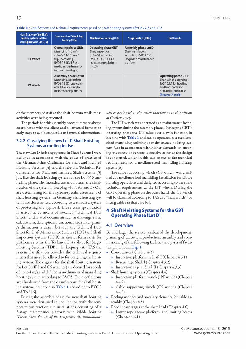
Table 1: Classifications and technical requirements posed on shaft hoisting systems after BVOS and TAS
Classifications of the Shaft Hoisting systems Lot D ac-
cording BVOS and TAS [4, 5]
“medium-sized” Manriding-Hoisting (TDS) Maintenance Hoisting (TDB) Stage Hoisting (TDBü) Shaft winch
IPF Winch
Operating phase GBT: Manriding (> 2 m/s, < 4m/s; 11-20 pers./trip), according BVOS § 3 (1), IPF as a medium sized manrid-ing platform (Fig. 4)
Operating phase GBT: Shaft inspection (< 4m/s), according BVOS § 2 (3) IPF as a maintenance platform (Fig. 3)
Assembly phase Lot D: Shaft installation, according BVOS § 2 (7) Unguided maintenance platform
CS Winch
Assembly phase Lot D: Manriding, according BVOS § 3 (2) rope guid-ed kibble hoisting to maintenance platform
- - Operating phase GBT: Shaft winch according TAS 10.1.1 for hooking and transportation of material and cable (Figures 7 and 8)

GeoResources Journal 3 | 2015
20Tunnelling
Gotthard Base Tunnel: The Sedrun Shaft Hoisting Systems – Part 2: Conversion and Operating PhaseFlender:
www.georesources.net
▷ Upper rope sheave platform with revolving ad-justable swivelling platform (Chapter 4.6.2)
▶ Airlock bank doors Shaft I (Chapter 4.7) ▶ Control and monitoring units ▶ Shaft station installations (Chapter 4.8)
▷ Shaft station steelwork cover at the shaft bottom (Chapter 4.8.1)
▷ Overwind braking device (Chapter 4.8.2)
4.2 New Concept for the Shaft Hoisting Systems – Exploiting Synergies
The parameters of the logistics and installation concept were considered when developing and designing the individual components of the Lot D shaft hoisting sys-tems. The clearance profiles of the access tunnel for ex-ample had to be taken into account, as a result of which the machine frame had to consist of multi-sectional welded steel construction for transport reasons then screwed together.
The tender for the new hoisting systems for Lot D permitted the components of the existing shaft hoisting facilities in Lot 356 to be taken over and utilized. The further exploitation of the following components was
agreed on with the client as a worthwhile measure dur-ing the Lot D conception phase:
▶ The existing hoisting machine fundament with the securely connected base plates for the old hoisting machines and brake stands were in a very good state and were able to be used for the Lot D shaft hoisting systems.
▶ The two new hoisting units were set on a massive machine frame, which catered for the safe distribu-tion of force into the existing base plates. Around 184 t of steelwork and engineering was deployed in the hoisting machine room.
▶ The main beams for the upper and lower rope sheave platforms were reutilized at the shaft inset. These major existing parts first of all served to support the new rope sheave platforms and secondly to safely distribute the force into the rock. In addition, the further utilization of the existing supporting struc-tures simplified the dismantling and assembly of the rope sheave platforms. Around 113 t of steelwork and engineering was involved in the head of blind shaft inset.
The synergy effects that were employed led to a great deal of money and time being saved, something which had a particularly beneficial outcome in ensuring that the narrow timetable was adhered to.
Certain groups of components, such as the adjust-able swivelling device, were subjected to thorough scrutiny in their final assembled state at the assembly halls in Haiger prior to being shipped. Subsequently the groups of components were given the green light for be-ing delivered and assembled.
4.3 Conveyances
4.3.1 Inspection Platform in Shaft IThe circular inspection platform (IPF) of the medium-sized manriding installation in Shaft I possesses a diam-eter of 6.4 m, a height of 8 m and a net weight of around 15 t. The IPF’s nominal payload amounts to 5 t, with an off-centre load of up to 3 t (e. g. cable drums) able to be carried on the base frame. The IPF is suspended on two ropes of the single drum blair winder. The suspension device, comprising a seesaw arrangement and a chain sling, compensates for the rope forces as well as static and dynamic changes in rope length during the wind-ing process. The slack rope protection installations are integrated in this suspension device. In the shaft the IPF is operated by roller guides with rubber torsion spring and guide shoes passing through two steel guidances lying opposite one another, with 7 m track gauge. The aggregate located centrally on the base frame caters for the independent supply of power for the lights and to operate the tools.
The gates for the IPF are to be found at the shaft head in the west and the shaft station in the south. Access to the IPF at the shaft head is facilitated by a platform, which also houses the control stand in a container. The
Fig. 3: Inspection platform (IPF) as maintenance platform with pluggable railings in parked position
GeoResources Journal 3 | 2015
21 Tunnelling
Gotthard Base Tunnel: The Sedrun Shaft Hoisting Systems – Part 2: Conversion and Operating PhaseFlender:
www.georesources.net
gap as danger zone between the access platform and the IPF is bridged by an integrated adjustable platform moved by hand. Should the IPF not be in use, it can be lowered on to the closed airlock bank doors. In this case, access is accomplished by means of a ladder via the negotiable closing bank doors from below to reach the parked IPF. The extendable access platform with over-head protection is located at the shaft station to bridge over the gap between the bottom at the shaft station and the IPF.
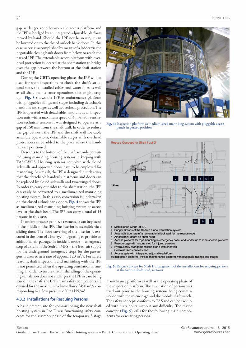
During the GBT’s operating phase, the IPF will be used for shaft inspections to check the shaft’s struc-tural state, the installed cables and water lines as well as all shaft maintenance operations that might crop up. Fig. 3 shows the IPF as maintenance platform with pluggable railings and stages including detachable handrails and stages as well as overhead protection. The IPF is operated with detachable handrails as an inspec-tion unit with a maximum speed of 4 m/s. For ventila-tion technical reasons it was designed to operate at a gap of 750 mm from the shaft wall. In order to reduce the gap between the IPF and the shaft wall for cable assembly operations, detachable stages with overhead protection can be added to the place where the hand-rails are positioned.
Descents to the bottom of the shaft are only permit-ted using manriding hoisting systems in keeping with TAS/BVOS. Hoisting systems complete with closed sidewalls and approved doors have to be employed for manriding. As a result, the IPF is designed in such a way that the detachable handrails, platforms and doors can be replaced by closed sidewalls and two-winged doors. In order to carry out rides to the shaft station, the IPF can easily be converted to a medium-sized manriding hoisting system. In this case, conversion is undertaken on the closed airlock bank doors. Fig. 4 shows the IPF as medium-sized manriding hoisting system at access level at the shaft head. The IPF can carry a total of 15 persons in this case.
In order to rescue people, a rescue cage can be placed in the middle of the IPF. The interior is accessible via a sliding door. The floor covering of the interior is exe-cuted in the form of a honeycomb grating to provide an additional air passage. In incident mode – emergency stop of a train in the Sedrun MFS – the fresh air supply for the underground emergency stops for the passen-gers is assured at a rate of approx. 120 m³/s. For safety reasons, shaft inspections and manriding with the IPF is not permitted when the operating ventilation is run-ning. In order to ensure that mishandling of the operat-ing ventilation does not endanger the IPF in case being stuck in the shaft, the IPF’s main safety components are devised for the maximum volume flow of 450 m³/s cor-responding to a flow pressure of 0.21 kN/m².
4.3.2 Installations for Rescuing PersonsA basic prerequisite for commissioning the new shaft hoisting system in Lot D was functioning safety con-cepts for the assembly phase of the temporary 3-stage
Fig. 4: Inspection platform as medium-sized manriding system with pluggable access panels in parked position
maintenance platform as well as the operating phase of the inspection platform. The evacuation of persons was tried out prior to the hoisting systems being commis-sioned with the rescue cage and the mobile shaft winch. The safety concepts conform to TAS and can be execut-ed within six hours without any difficulty. The rescue concept (Fig. 5) calls for the following main compo-nents for evacuating persons:
Fig. 5: Rescue concept for Shaft I: arrangement of the installations for rescuing persons at the Sedrun shaft head, sections
GeoResources Journal 3 | 2015
22Tunnelling
Gotthard Base Tunnel: The Sedrun Shaft Hoisting Systems – Part 2: Conversion and Operating PhaseFlender:
www.georesources.net
▶ Mobile shaft winch (Lot 372) ▶ Rescue platform to place the rope ▶ Rescue crane with bracket to be anchored in the con-
crete floor ▶ Rescue cage with room for a rescue sled to recover
injured persons
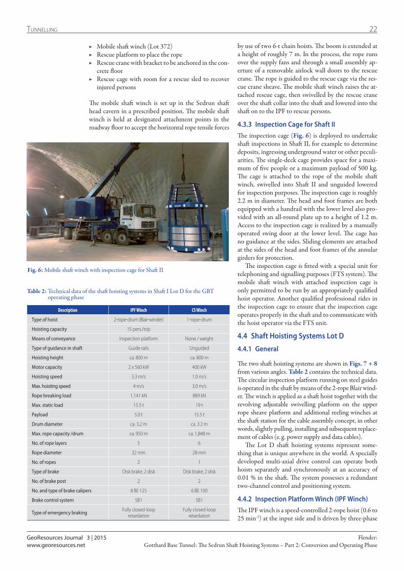
The mobile shaft winch is set up in the Sedrun shaft head cavern in a prescribed position. The mobile shaft winch is held at designated attachment points in the roadway floor to accept the horizontal rope tensile forces
by use of two 6-t chain hoists. The boom is extended at a height of roughly 7 m. In the process, the rope runs over the supply fans and through a small assembly ap-erture of a removable airlock wall doors to the rescue crane. The rope is guided to the rescue cage via the res-cue crane sheave. The mobile shaft winch raises the at-tached rescue cage, then swivelled by the rescue crane over the shaft collar into the shaft and lowered into the shaft on to the IPF to rescue persons.
4.3.3 Inspection Cage for Shaft IIThe inspection cage (Fig. 6) is deployed to undertake shaft inspections in Shaft II, for example to determine deposits, ingressing underground water or other peculi-arities. The single-deck cage provides space for a maxi-mum of five people or a maximum payload of 500 kg. The cage is attached to the rope of the mobile shaft winch, swivelled into Shaft II and unguided lowered for inspection purposes. The inspection cage is roughly 2.2 m in diameter. The head and foot frames are both equipped with a handrail with the lower level also pro-vided with an all-round plate up to a height of 1.2 m. Access to the inspection cage is realized by a manually operated swing door at the lower level. The cage has no guidance at the sides. Sliding elements are attached at the sides of the head and foot frames of the annular girders for protection.
The inspection cage is fitted with a special unit for telephoning and signalling purposes (FTS system). The mobile shaft winch with attached inspection cage is only permitted to be run by an appropriately qualified hoist operator. Another qualified professional rides in the inspection cage to ensure that the inspection cage operates properly in the shaft and to communicate with the hoist operator via the FTS unit.
4.4 Shaft Hoisting Systems Lot D
4.4.1 General
The two shaft hoisting systems are shown in Figs. 7 + 8 from various angles. Table 2 contains the technical data. The circular inspection platform running on steel guides is operated in the shaft by means of the 2-rope Blair wind-er. The winch is applied as a shaft hoist together with the revolving adjustable swivelling platform on the upper rope sheave platform and additional reeling winches at the shaft station for the cable assembly concept, in other words, slightly pulling, installing and subsequent replace-ment of cables (e. g. power supply and data cables).
The Lot D shaft hoisting systems represent some-thing that is unique anywhere in the world. A specially developed multi-axial drive control can operate both hoists separately and synchronously at an accuracy of 0.01 % in the shaft. The system possesses a redundant two-channel control and positioning system.
4.4.2 Inspection Platform Winch (IPF Winch)The IPF winch is a speed-controlled 2-rope hoist (0.6 to 25 min-1) at the input side and is driven by three-phase
Description IPF Winch CS Winch
Type of hoist 2-rope-drum (Blair-winder) 1-rope-drum
Hoisting capacity 15 pers./trip -
Means of conveyance Inspection platform None / weight
Type of guidance in shaft Guide rails Unguided
Hoisting height ca. 800 m ca. 800 m
Motor capacity 2 x 560 kW 400 kW
Hoisting speed 3.3 m/s 1.0 m/s
Max. hoisting speed 4 m/s 3.0 m/s
Rope breaking load 1,141 kN 889 kN
Max. static load 15.5 t 19 t
Payload 5.0 t 15.5 t
Drum diameter ca. 3,2 m ca. 3.2 m
Max. rope capacity /drum ca. 950 m ca. 1,848 m
No. of rope layers 5 6
Rope diameter 32 mm 28 mm
No. of ropes 2 1
Type of brake Disk brake, 2 disk Disk brake, 2 disk
No. of brake post 2 2
No. and type of brake calipers 8 BE 125 6 BE 100
Brake control system SB1 SB1
Type of emergency braking Fully closed-loop retardation
Fully closed-loop retardation
Table 2: Technical data of the shaft hoisting systems in Shaft I Lot D for the GBT operating phase
Fig. 6: Mobile shaft winch with inspection cage for Shaft II
GeoResources Journal 3 | 2015
23 Tunnelling
Gotthard Base Tunnel: The Sedrun Shaft Hoisting Systems – Part 2: Conversion and Operating PhaseFlender:
www.georesources.net
supporting rope runs underlay and possesses a nominal diameter of 28 mm.
The speed-controlled (0.16 to 20 min-1) CS winch is driven by a three-phase motor (400 kW) and a bevel helical gear unit. The driving shaft runs on dual anti-friction bearings. The drive motor and the gear unit are connected with each other by an elastic jaw coupling with motor brake.
The braking forces produced by the combined driv-ing and safety brake are distributed over two brake stands each with four pairs of brake elements (totalling 12 x BE 100). These act on one brake disc per drum. The Siemag disc brake control SB 1 with electro-hydraulical-ly regulated safety brake is utilized for load-independent adjustable deceleration values.
During the assembly phase the CS winch was utilized for operating the temporary kibble hoisting system. A guide cradle with kibble was attached to the IPF ropes of the temporary maintance platform. The CS winch was used as a medium-sized manriding hoisting system during this phase and set up in keeping with Table 1. The CS winch’s driving machine thus was equipped with a reversible gear. The maximum travelling speed for hoisting the kibble amounted to 3 m/s. During the operating phase the winch serves as a shaft winch. In this case, the speed is restricted to 1 m/s for transport-ing material as well as assembling cables.
4.5 Reeling Winches and ancillary Elements for Cable Assembly
Safe and efficient handling of the ropes and cables is of paramount significance given increasing depth and in turn, increasing loads when cables are being assembled in the shaft. Two electrically operated reeling winches and a guide sheave were supplied for the complicated cable assembly sequences starting from the shaft station
current motors (2 x 560 kW) via a bevel helical gear unit.
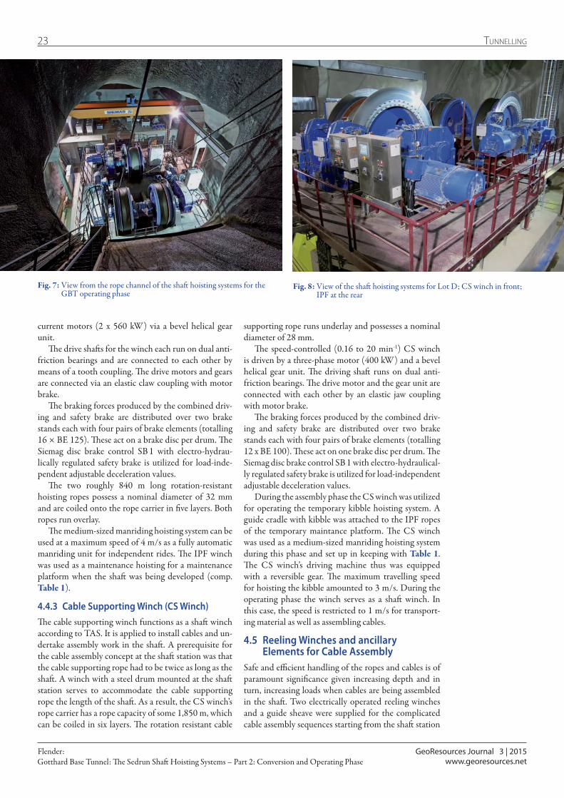
The drive shafts for the winch each run on dual anti-friction bearings and are connected to each other by means of a tooth coupling. The drive motors and gears are connected via an elastic claw coupling with motor brake.
The braking forces produced by the combined driv-ing and safety brake are distributed over two brake stands each with four pairs of brake elements (totalling 16 × BE 125). These act on a brake disc per drum. The Siemag disc brake control SB 1 with electro-hydrau-lically regulated safety brake is utilized for load-inde-pendent adjustable deceleration values.
The two roughly 840 m long rotation-resistant hoisting ropes possess a nominal diameter of 32 mm and are coiled onto the rope carrier in five layers. Both ropes run overlay.
The medium-sized manriding hoisting system can be used at a maximum speed of 4 m/s as a fully automatic manriding unit for independent rides. The IPF winch was used as a maintenance hoisting for a maintenance platform when the shaft was being developed (comp. Table 1).
4.4.3 Cable Supporting Winch (CS Winch)The cable supporting winch functions as a shaft winch according to TAS. It is applied to install cables and un-dertake assembly work in the shaft. A prerequisite for the cable assembly concept at the shaft station was that the cable supporting rope had to be twice as long as the shaft. A winch with a steel drum mounted at the shaft station serves to accommodate the cable supporting rope the length of the shaft. As a result, the CS winch’s rope carrier has a rope capacity of some 1,850 m, which can be coiled in six layers. The rotation resistant cable
Fig. 7: View from the rope channel of the shaft hoisting systems for the GBT operating phase
Fig. 8: View of the shaft hoisting systems for Lot D; CS winch in front; IPF at the rear

GeoResources Journal 3 | 2015
24Tunnelling
Gotthard Base Tunnel: The Sedrun Shaft Hoisting Systems – Part 2: Conversion and Operating PhaseFlender:
www.georesources.net
at Sedrun. The drives of the two reeling winches oper-ate independently, i. e. they do not depend on the IPF and CS winch control system (Table 3). The operators can control the speed and the running direction of the reeling winches via a manual control unit. The double-shoe brake works according to the discharge principle, i. e. the brake gripping force is produced by a group of weights so that the coiled rope or cable can be pulled from the reeling winch with a defined counter-pull force (shown in Fig. 1).
Fig. 9 displays the two reeling winches set up at the shaft station, which are operated together with the CS winch at the shaft head. Table 3 provides the technical data. The reeling winch (Fig. 9, at the rear, left) pos-sesses a steel drum with 1.5 m diameter for coiling the cable supporting rope for the CS winch or some other rope.
The second reeling winch serves to accept varying large and wide cable drums produced by different man-ufacturers. The basic frame of this reeling winch can be correspondingly modified for the various cable drums.
4.6 Rope Sheave Stages at the Shaft HeadThe design of the new rope sheave platforms at the shaft head is shown in Fig. 10 and Fig. 11 displays a photo of the integrated revolving adjustable swivelling platform. The rope sheave platforms are set up on the main girders taken over from Lot 356 and the concrete foundation located between the hoisting system room and Shaft I to safely transfer forces in the rock. The rope sheaves for the IPF winch are to be found on the lower rope sheave platform. An adjustable swivelling platform rotatable by 360° (revolving platform) is located on the upper rope sheave platform to guide the cable supporting rope into the appropriate cable sectors in Shaft I (Fig. 11).
4.6.1 Lower Rope Sheave Platform and limiting Beams
The rope sheaves for the IPF winch are set up on the lower rope sheave platform. During the assembly phase, the CS winch’s two vertical rope sheaves for the rope-guided kibble manriding hoisting system are located here.
Contrary to TAS specifications an overwind pro-tection device for the IPF was found unnecessary and therefore was not used in the upper shaft head area. It was established that no upwards directed force can be present when the IPF winch travels upwards – for in-stance in the event of a power cut. The IPF is brought to a standstill within a sufficiently short distance through gravity. Uncontrolled overrunning at high speed can be precluded as the IPF’s travelling speed was restricted to 1 m/s by the hoisting controler in the shaft head area and furthermore there is a free height of 20 m until the arresting devices are reached. As a result of these obser-vations and measures that were undertaken an equiva-lent safety level was attained. The limiting beams serve as a final overrunning buffer and are mounted below the lower rope sheave stage [6].
Table 3: Technical data for the two reeling winches
Reeler With steel drum For cable drums
Drum diameter 1,500 mm 4,000 mm/ 3,200 mm
Torque 11.64 kNm 11.64 kNm
Rope traction force 51 to 35 kN 20 to 10 kN
Rope speed 0 to 0.36 m/s 0 to 1.2 m/s
Gear ratio 79.75 : 1 79.75 : 1
Chain gear 21 / 45 21 / 80
Engine speed 975 rpm 975 rpm
Weight without drum 7,350 kg 9,500 kg
Permissible gross weight 38,000 kg 38,000 kg
Fig. 10: Rope sheave platform with integrated revolving adjustable swivelling platform
Fig. 9: Set-up of the two reeling winches for assembling cables at the shaft bottom
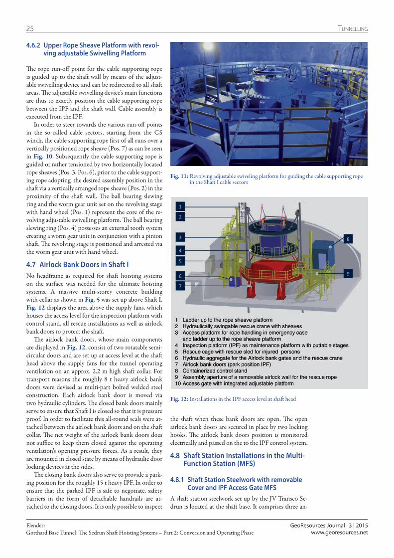
GeoResources Journal 3 | 2015
25 Tunnelling
Gotthard Base Tunnel: The Sedrun Shaft Hoisting Systems – Part 2: Conversion and Operating PhaseFlender:
www.georesources.net
4.6.2 Upper Rope Sheave Platform with revol-ving adjustable Swivelling Platform
The rope run-off point for the cable supporting rope is guided up to the shaft wall by means of the adjust-able swivelling device and can be redirected to all shaft areas. The adjustable swivelling device’s main functions are thus to exactly position the cable supporting rope between the IPF and the shaft wall. Cable assembly is executed from the IPF.
In order to steer towards the various run-off points in the so-called cable sectors, starting from the CS winch, the cable supporting rope first of all runs over a vertically positioned rope sheave (Pos. 7) as can be seen in Fig. 10. Subsequently the cable supporting rope is guided or rather tensioned by two horizontally located rope sheaves (Pos. 3, Pos. 6), prior to the cable support-ing rope adopting the desired assembly position in the shaft via a vertically arranged rope sheave (Pos. 2) in the proximity of the shaft wall. The ball bearing slewing ring and the worm gear unit set on the revolving stage with hand wheel (Pos. 1) represent the core of the re-volving adjustable swivelling platform. The ball bearing slewing ring (Pos. 4) possesses an external tooth system creating a worm gear unit in conjunction with a pinion shaft. The revolving stage is positioned and arrested via the worm gear unit with hand wheel.
4.7 Airlock Bank Doors in Shaft INo headframe as required for shaft hoisting systems on the surface was needed for the ultimate hoisting systems. A massive multi-storey concrete building with cellar as shown in Fig. 5 was set up above Shaft I. Fig. 12 displays the area above the supply fans, which houses the access level for the inspection platform with control stand, all rescue installations as well as airlock bank doors to protect the shaft.
The airlock bank doors, whose main components are displayed in Fig. 12, consist of two rotatable semi-circular doors and are set up at access level at the shaft head above the supply fans for the tunnel operating ventilation on an approx. 2.2 m high shaft collar. For transport reasons the roughly 8 t heavy airlock bank doors were devised as multi-part bolted welded steel construction. Each airlock bank door is moved via two hydraulic cylinders. The closed bank doors mainly serve to ensure that Shaft I is closed so that it is pressure proof. In order to facilitate this all-round seals were at-tached between the airlock bank doors and on the shaft collar. The net weight of the airlock bank doors does not suffice to keep them closed against the operating ventilation’s opening pressure forces. As a result, they are mounted in closed state by means of hydraulic door locking devices at the sides.
The closing bank doors also serve to provide a park-ing position for the roughly 15 t heavy IPF. In order to ensure that the parked IPF is safe to negotiate, safety barriers in the form of detachable handrails are at-tached to the closing doors. It is only possible to inspect
the shaft when these bank doors are open. The open airlock bank doors are secured in place by two locking hooks. The airlock bank doors position is monitored electrically and passed on the to the IPF control system.
4.8 Shaft Station Installations in the Multi-Function Station (MFS)
4.8.1 Shaft Station Steelwork with removable Cover and IPF Access Gate MFS
A shaft station steelwork set up by the JV Transco Se-drun is located at the shaft base. It comprises three an-
Fig. 11: Revolving adjustable swiveling platform for guiding the cable supporting rope in the Shaft I cable sectors
Fig. 12: Installations in the IPF access level at shaft head

GeoResources Journal 3 | 2015
26Tunnelling
Gotthard Base Tunnel: The Sedrun Shaft Hoisting Systems – Part 2: Conversion and Operating PhaseFlender:
www.georesources.net
nular girders and five support girders. The round shaft station steelwork shown in Fig. 13 is firmly connected with the western concrete wall acting as an call bell sys-tem thus representing an essential component of the shaft hoisting system. A manually operated access plat-form with overhead protection integrated in the shaft station steelwork permits the IPF facility to be entered and exited in a safe manner.
The safety installations at the shaft station steelwork were devised in the form of safety access panels and high-tensile wire mesh screen for easy removal. It was essential to ensure that the safety cover installations es-pecially in the upper and central sections of the shaft station steelwork allow a sufficient amount of operating ventilation (450 m³/s) to pass through quite apart from their actual protective function. Furthermore, apertures as well as access possibilities had to be allowed for in the upper shaft station steelwork area for the designated power supply and data cables as well as a water pipeline.
As a consequence, safety mesh screen were hung up as curtains in the upper and central sections of the shaft station steelwork, which were simply opened if required. These safety mesh screens are attached to a continuous steel rope mounted to the shaft wall above the shaft station steelwork.
In the lower section of the shaft station steelwork perforated removable access panels as partitioning safe-ty installations were foreseen as is customary in min-ing. The supporting steel structure specially devised for the round station steelwork enables the roughly 35 kg heavy perforated plate segments to be dismantled easily and without complications if cables have to be assem-bled in future.
4.8.2 Overwind Braking Devices in the Shaft Sump
Fig. 14 shows the overwind braking devices – Type Sie-mag Tecberg Safety Arrestor – subsequently known as the SSA system. The old shaft sump was filled up with material. A massive concrete slab was then positioned to float on the backfilled shaft sump to round things off. As the fill material is unlikely to be seriously affected by settlement, the base slab was not connected to the shaft wall. The introduction of braking forces into the shaft wall, which is customary in mining, had to be avoided.
For this reason the SSA system was devised as a self-supporting steel structure, guided by four brackets at the sides to cope with settlement. The braking forces and the SSA system’s own weight are supported by the steel structure and transferred to the base slab in a verti-cal direction. The SSA system is designed to cope with a total weight of 21,000 kg for the IPF and an impact speed of 4 m/s. It operates with a maximum braking path of 2.4 m given full payload. The arrestor frame geometry is devised in such a way that the arrestor aggregate mounted below the IPF platform can dip between the arrestor frames in the event of impact.
5 Summary – Part 2Shaft I possessed a key function for the conversion phase of the shaft hoisting systems and shafts in Sedrun. It also played an essential role in ensuring that the over-all timetable for the Gotthard Base Tunnel (GBT) was adhered to. The amount of time available for the con-version phase called for ongoing optimizations of the logistics and installation concept. The substantial and complex steelwork and engineering components were
Fig. 13: Shaft station steelwork with shaft access gate, call bell system, removable access panels and high-tensile wire mesh screen
Fig. 14: Overwind braking device Siemag Tecberg Safety Arrestor (SSA) at the shaft bottom frame
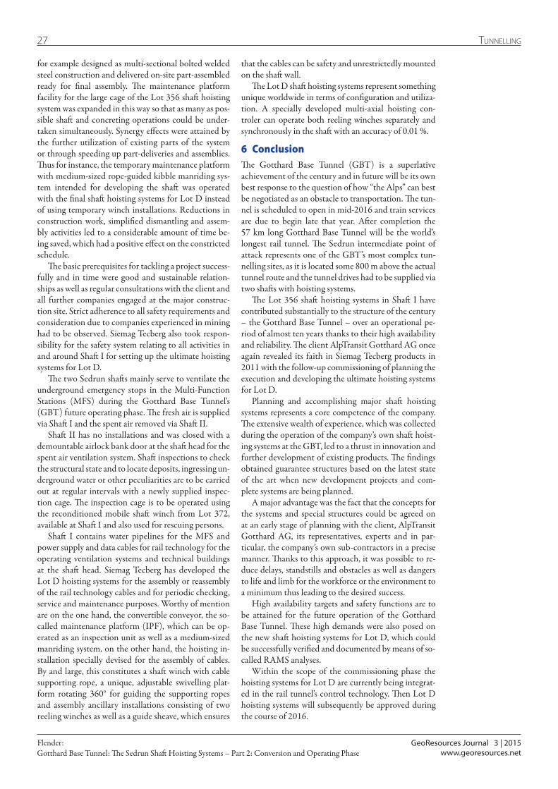
GeoResources Journal 3 | 2015
27 Tunnelling
Gotthard Base Tunnel: The Sedrun Shaft Hoisting Systems – Part 2: Conversion and Operating PhaseFlender:
www.georesources.net
for example designed as multi-sectional bolted welded steel construction and delivered on-site part-assembled ready for final assembly. The maintenance platform facility for the large cage of the Lot 356 shaft hoisting system was expanded in this way so that as many as pos-sible shaft and concreting operations could be under-taken simultaneously. Synergy effects were attained by the further utilization of existing parts of the system or through speeding up part-deliveries and assemblies. Thus for instance, the temporary maintenance platform with medium-sized rope-guided kibble manriding sys-tem intended for developing the shaft was operated with the final shaft hoisting systems for Lot D instead of using temporary winch installations. Reductions in construction work, simplified dismantling and assem-bly activities led to a considerable amount of time be-ing saved, which had a positive effect on the constricted schedule.
The basic prerequisites for tackling a project success-fully and in time were good and sustainable relation-ships as well as regular consultations with the client and all further companies engaged at the major construc-tion site. Strict adherence to all safety requirements and consideration due to companies experienced in mining had to be observed. Siemag Tecberg also took respon-sibility for the safety system relating to all activities in and around Shaft I for setting up the ultimate hoisting systems for Lot D.
The two Sedrun shafts mainly serve to ventilate the underground emergency stops in the Multi-Function Stations (MFS) during the Gotthard Base Tunnel’s (GBT) future operating phase. The fresh air is supplied via Shaft I and the spent air removed via Shaft II.
Shaft II has no installations and was closed with a demountable airlock bank door at the shaft head for the spent air ventilation system. Shaft inspections to check the structural state and to locate deposits, ingressing un-derground water or other peculiarities are to be carried out at regular intervals with a newly supplied inspec-tion cage. The inspection cage is to be operated using the reconditioned mobile shaft winch from Lot 372, available at Shaft I and also used for rescuing persons.
Shaft I contains water pipelines for the MFS and power supply and data cables for rail technology for the operating ventilation systems and technical buildings at the shaft head. Siemag Tecberg has developed the Lot D hoisting systems for the assembly or reassembly of the rail technology cables and for periodic checking, service and maintenance purposes. Worthy of mention are on the one hand, the convertible conveyor, the so-called maintenance platform (IPF), which can be op-erated as an inspection unit as well as a medium-sized manriding system, on the other hand, the hoisting in-stallation specially devised for the assembly of cables. By and large, this constitutes a shaft winch with cable supporting rope, a unique, adjustable swivelling plat-form rotating 360° for guiding the supporting ropes and assembly ancillary installations consisting of two reeling winches as well as a guide sheave, which ensures
that the cables can be safety and unrestrictedly mounted on the shaft wall.
The Lot D shaft hoisting systems represent something unique worldwide in terms of configuration and utiliza-tion. A specially developed multi-axial hoisting con-troler can operate both reeling winches separately and synchronously in the shaft with an accuracy of 0.01 %.
6 ConclusionThe Gotthard Base Tunnel (GBT) is a superlative achievement of the century and in future will be its own best response to the question of how “the Alps” can best be negotiated as an obstacle to transportation. The tun-nel is scheduled to open in mid-2016 and train services are due to begin late that year. After completion the 57 km long Gotthard Base Tunnel will be the world’s longest rail tunnel. The Sedrun intermediate point of attack represents one of the GBT’s most complex tun-nelling sites, as it is located some 800 m above the actual tunnel route and the tunnel drives had to be supplied via two shafts with hoisting systems.
The Lot 356 shaft hoisting systems in Shaft I have contributed substantially to the structure of the century – the Gotthard Base Tunnel – over an operational pe-riod of almost ten years thanks to their high availability and reliability. The client AlpTransit Gotthard AG once again revealed its faith in Siemag Tecberg products in 2011 with the follow-up commissioning of planning the execution and developing the ultimate hoisting systems for Lot D.
Planning and accomplishing major shaft hoisting systems represents a core competence of the company. The extensive wealth of experience, which was collected during the operation of the company’s own shaft hoist-ing systems at the GBT, led to a thrust in innovation and further development of existing products. The findings obtained guarantee structures based on the latest state of the art when new development projects and com-plete systems are being planned.
A major advantage was the fact that the concepts for the systems and special structures could be agreed on at an early stage of planning with the client, AlpTransit Gotthard AG, its representatives, experts and in par-ticular, the company’s own sub-contractors in a precise manner. Thanks to this approach, it was possible to re-duce delays, standstills and obstacles as well as dangers to life and limb for the workforce or the environment to a minimum thus leading to the desired success.
High availability targets and safety functions are to be attained for the future operation of the Gotthard Base Tunnel. These high demands were also posed on the new shaft hoisting systems for Lot D, which could be successfully verified and documented by means of so-called RAMS analyses.
Within the scope of the commissioning phase the hoisting systems for Lot D are currently being integrat-ed in the rail tunnel’s control technology. Then Lot D hoisting systems will subsequently be approved during the course of 2016.
28Tunnelling
7 References
[1] Flender, M. (2015). Gotthard-Basistunnel: Die Schachtförderanlagen von Sedrun – Teil 1: Rohbauphase. GeoResources Zeitschrift, (1-2015), 25-34.
[2] Flender, M. (2015). Gotthard Base Tunnel: The Sedrun Shaft Hoisting Systems – Part 1: Tunnel Construction Phase. GeoResources Journal (2-2015), 18-28.
[3] Schweizer Unfallverhütungsvorschriften, Art. 9 VUV: https://www.koordination.ch/de/online-handbuch/uvg/unfallverhuetung/arbeitssicherheit/pflichten/#c39664 Online: zuletzt aufgerufen am 24.8.2015
[4] Bergverordnung für Schacht- und Schrägförderanlagen (BVOS) Stand: 15.10.2003
[5] Technische Anforderungen an Schacht- und Schrägförderanlagen (TAS) Stand: Dezember 2005
[6] Interner Prüfbericht der DMT, unveröffentlicht
AlpTransit Gotthard AGThe AlpTransit Gotthard AG is the client for the new Gotthard axis rail route passing through the Alps including the Gotthard and Ceneri Base Tun-nels. Founded in 1998, the SBB subsidiary today employs around 160 staff at its Lucerne head-quarters and at its branches in Altford, Sedrun, Faido and Bellinzona.
AuthorDipl.-Ing. Michael Flender (born 1978), Project Manager Hoisting Technology, SIEMAG TECBERG GmbH, was the re-sponsible part-project manager for upgrad-ing the mechanical components for the Sedrun shaft hoisting systems from 2011 to initial operation in 2014.
Contact: [email protected]
Take advantage of the opportunity at the “tunnellers’ get-together” to learn all about future topics for the industry and exchange views with colleagues from all over the world. Attend the STUVA Conference from December 1–3 in Dortmund!
More than 1,500 participants from over 20 countries
The world’s No. 1 event for underground construction
Accompanying exhibition with more than 150 exhibitors from home and abroad
STUVA Conference 2015
International Forum for Tunnels and Infrastructure
December 1–3, 2015 · Dortmund, Germany
www.stuva-conference.comwww.stuva-expo.com
STUVA e. V.Mathias-Brueggen-Str. 41, D-50827 Köln/ColognePhone +49 221 59795-0, Fax +49 221 59795-50E-Mail: [email protected]
New focus on tunnel operation!
STUVA-Tagung_Anz_EN_210x142_2015-08-28.indd 1 28.08.15 14:13
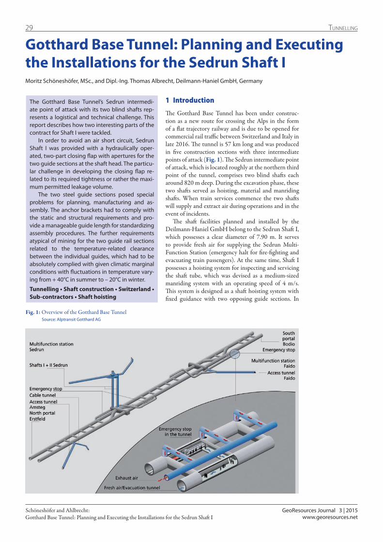
GeoResources Journal 3 | 2015
29 Tunnelling
Gotthard Base Tunnel: Planning and Executing the Installations for the Sedrun Shaft ISchöneshöfer and Ahlbrecht:
www.georesources.net
Gotthard Base Tunnel: Planning and Executing the Installations for the Sedrun Shaft IMoritz Schöneshöfer, MSc., and Dipl.-Ing. Thomas Albrecht, Deilmann-Haniel GmbH, Germany
1 Introduction
The Gotthard Base Tunnel has been under construc-tion as a new route for crossing the Alps in the form of a flat trajectory railway and is due to be opened for commercial rail traffic between Switzerland and Italy in late 2016. The tunnel is 57 km long and was produced in five construction sections with three intermediate points of attack (Fig. 1). The Sedrun intermediate point of attack, which is located roughly at the northern third point of the tunnel, comprises two blind shafts each around 820 m deep. During the excavation phase, these two shafts served as hoisting, material and manriding shafts. When train services commence the two shafts will supply and extract air during operations and in the event of incidents.
The shaft facilities planned and installed by the Deilmann-Haniel GmbH belong to the Sedrun Shaft I, which possesses a clear diameter of 7.90 m. It serves to provide fresh air for supplying the Sedrun Multi-Function Station (emergency halt for fire-fighting and evacuating train passengers). At the same time, Shaft I possesses a hoisting system for inspecting and servicing the shaft tube, which was devised as a medium-sized manriding system with an operating speed of 4 m/s. This system is designed as a shaft hoisting system with fixed guidance with two opposing guide sections. In
The Gotthard Base Tunnel’s Sedrun intermedi-ate point of attack with its two blind shafts rep-resents a logistical and technical challenge. This report describes how two interesting parts of the contract for Shaft I were tackled.
In order to avoid an air short circuit, Sedrun Shaft I was provided with a hydraulically oper-ated, two-part closing flap with apertures for the two guide sections at the shaft head. The particu-lar challenge in developing the closing flap re-lated to its required tightness or rather the maxi-mum permitted leakage volume.
The two steel guide sections posed special problems for planning, manufacturing and as-sembly. The anchor brackets had to comply with the static and structural requirements and pro-vide a manageable guide length for standardizing assembly procedures. The further requirements atypical of mining for the two guide rail sections related to the temperature-related clearance between the individual guides, which had to be absolutely complied with given climatic marginal conditions with fluctuations in temperature vary-ing from + 40°C in summer to – 20°C in winter.
Tunnelling • Shaft construction • Switzerland • Sub-contractors • Shaft hoisting
Fig. 1: Overview of the Gotthard Base Tunnel Source: Alptransit Gotthard AG
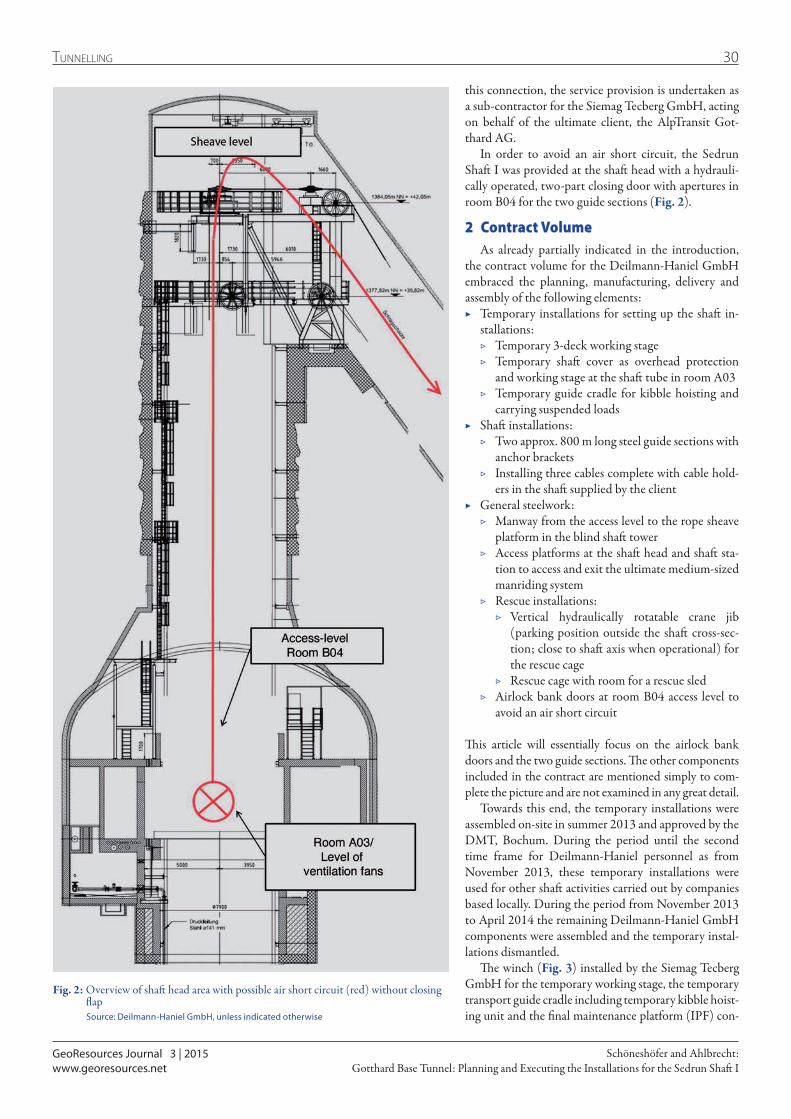
GeoResources Journal 3 | 2015
30Tunnelling
Gotthard Base Tunnel: Planning and Executing the Installations for the Sedrun Shaft ISchöneshöfer and Ahlbrecht:
www.georesources.net
this connection, the service provision is undertaken as a sub-contractor for the Siemag Tecberg GmbH, acting on behalf of the ultimate client, the AlpTransit Got-thard AG.
In order to avoid an air short circuit, the Sedrun Shaft I was provided at the shaft head with a hydrauli-cally operated, two-part closing door with apertures in room B04 for the two guide sections (Fig. 2).
2 Contract VolumeAs already partially indicated in the introduction,
the contract volume for the Deilmann-Haniel GmbH embraced the planning, manufacturing, delivery and assembly of the following elements:
▶ Temporary installations for setting up the shaft in-stallations:
▷ Temporary 3-deck working stage ▷ Temporary shaft cover as overhead protection
and working stage at the shaft tube in room A03 ▷ Temporary guide cradle for kibble hoisting and
carrying suspended loads ▶ Shaft installations:
▷ Two approx. 800 m long steel guide sections with anchor brackets
▷ Installing three cables complete with cable hold-ers in the shaft supplied by the client
▶ General steelwork: ▷ Manway from the access level to the rope sheave
platform in the blind shaft tower ▷ Access platforms at the shaft head and shaft sta-
tion to access and exit the ultimate medium-sized manriding system
▷ Rescue installations: ▷ Vertical hydraulically rotatable crane jib
(parking position outside the shaft cross-sec-tion; close to shaft axis when operational) for the rescue cage
▷ Rescue cage with room for a rescue sled ▷ Airlock bank doors at room B04 access level to
avoid an air short circuit
This article will essentially focus on the airlock bank doors and the two guide sections. The other components included in the contract are mentioned simply to com-plete the picture and are not examined in any great detail.
Towards this end, the temporary installations were assembled on-site in summer 2013 and approved by the DMT, Bochum. During the period until the second time frame for Deilmann-Haniel personnel as from November 2013, these temporary installations were used for other shaft activities carried out by companies based locally. During the period from November 2013 to April 2014 the remaining Deilmann-Haniel GmbH components were assembled and the temporary instal-lations dismantled.
The winch (Fig. 3) installed by the Siemag Tecberg GmbH for the temporary working stage, the temporary transport guide cradle including temporary kibble hoist-ing unit and the final maintenance platform (IPF) con-
Fig. 2: Overview of shaft head area with possible air short circuit (red) without closing flap
Source: Deilmann-Haniel GmbH, unless indicated otherwise

GeoResources Journal 3 | 2015
31 Tunnelling
Gotthard Base Tunnel: Planning and Executing the Installations for the Sedrun Shaft ISchöneshöfer and Ahlbrecht:
www.georesources.net
sists of a single drum blair machine with 2 ropes, which is devised for speeds of up to 4 m/s. A further drum hoisting system (cable supporting rope winch) is avail-able for the transport guide cradle together with the kib-ble hoisting system and for the subsequent insertion of high and medium voltage cables in the Sedrun Shaft I.
The hoist’s special feature is that the cable support-ing winch can be operated synchronized with the stage winch unit. Furthermore, the depth accuracy achieved when using the stage winch is extremely large. Vertical positioning within the range of a few cm can be at-tained without any difficulty.
3 Planning ServicesVarious challenges and special features had to be tack-led and taken into consideration during the technical and organizational planning process. These are exam-ined individually as follows.
3.1 Technical Challenges and special Features
At this point the two-part airlock bank doors and the two guide sections deserve particular mention. Essentially, the airlock bank doors represents the de-velopment of a prototype, which caters for practically no time-related margin for corrective procedures be-tween in-house acceptance on the part of the supplier (manufacturer) and on-site installation. The two guide sections had to comply with requirements atypical of mining, which affected planning, production as well as assembly.
3.1.1 Airlock Bank DoorsThe two-part hydraulic airlock bank doors (Fig. 4) was executed as a modular structure, with each half com-prising four individual segments, which were bolted together on-site. The airlock bank doors’ overall diam-eter amounts to approx. 8.0 m given a weight of roughly 8.0 t per half.
Each half rests on two main brackets by means of a hydraulic cylinder. Two locking brackets were set up at the face side of the two halves outside the shaft cross-section, which extend a locking wedge on to an abut-ment when the airlock bank door is in closed mode to secure the door against the ventilation overpressure produced by the air intake fans located underneath. As the airlock bank doors is located within the path trav-elled by the IPF and the IPF’s parking position in stand-ard mode lies above the closed protection door, both guide sections had to pass through the door. Towards this end, apertures were provided in the door, through which the guides could be fed. The special challenge in developing the airlock bank doors related to the required tightness or rather the maximum permissible leakage volume flow. Four elements were identified as possible sources of leakages:
▶ The face between the two door halves ▶ The airlock bank doors’ contact area on the concrete
shaft collar
Fig. 3: Siemag Tecberg winch unit
Fig. 4: Overview of the closing flap
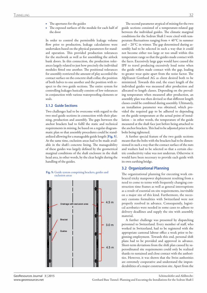
GeoResources Journal 3 | 2015
32Tunnelling
Gotthard Base Tunnel: Planning and Executing the Installations for the Sedrun Shaft ISchöneshöfer and Ahlbrecht:
www.georesources.net
The second parameter atypical of mining for the two guide sections consisted of a temperature-related gap between the individual guides. The climatic marginal conditions for the Sedrun Shaft I were cited with tem-perature fluctuations ranging from + 40 °C in summer and – 20 °C in winter. The gap determined during as-sembly had to be selected in such a way that it could not become either too large or too small within this temperature range so that the guides made contact with the faces. Excessively large gaps would have caused the IPF to travel producing excessively loud noise when the guide rollers made contact with the gap, leading to greater wear quite apart from the noise factor. The AlpTransit Gotthard AG as client desired both to be minimized. Towards this end, the exact length of the individual guides was measured after production and allocated to length classes. Depending on the prevail-ing temperature when measured after production, an assembly plan was then devised so that different length classes could be combined during assembly. Ultimately, an installation parameter was obtained, which pro-vided the required gap to be adhered to depending on the guide temperature at the actual point of instal-lation – in other words, the temperature of the guide measured at the shaft face just before being attached to the anchor brackets. This had to be adjusted prior to the bolts being tightened.
A further special feature of the two guide sections meant that the bolts with the brackets had to be dimen-sioned in such a way that the contact surface of the nuts and washers had to be selected so that a certain elec-tric conductivity value was not underrun. Otherwise it would have been necessary to provide each guide with its own earthing bridge.
3.2 Organizational PlanningThe organizational planning for executing work em-braced tricky manpower deployment resulting from a need to come to terms with frequently changing con-struction time frames as well as general interruptions as a result of essential on-site requirements, inevitable on a major site of this kind. Furthermore, the neces-sary customs formalities with Switzerland were not properly resolved in advance. Consequently, logisti-cal acrobatics were needed in some cases to adhere to delivery deadlines and supply the site with assembly material.
A further challenge was presented by dispatching personnel to Switzerland. Every member of staff, who worked in Switzerland, had to be registered with the appropriate cantonal labour office a week prior to be-ginning employment. Towards this end, personal shift plans had to be provided and approved in advance. Short-term deviations from the shift plan caused by su-perordinated site requirements could only be realized thanks to sustained and close contact with the authori-ties. However, it was shown that the Swiss authorities are extremely cooperative and understand the impon-derabilities of a major construction site. Apart from the
Fig. 5: Guide system comprising brackets, guides and exclusion areas
▶ The apertures for the guides ▶ The exposed surfaces of the module for each half of
the door
In order to control the permissible leakage volume flow prior to production, leakage calculations were undertaken based on the physical parameters for stand-ard operation. This provided production tolerances for the steelwork as well as for assembling the airlock bank doors. In this connection, the production toler-ances largely related to just how precisely the individual modules fitted one another. The positional tolerances for assembly restricted the amount of play accorded the contact surface on the concrete shaft collar, the position of both halves to one another and the position with re-spect to the two guide sections. The entire system for controlling leakages basically consists of low tolerances in conjunction with various waterproofing elements or seals.
3.1.2 Guide SectionsTwo challenges had to be overcome with regard to the two steel guide sections in connection with their plan-ning, production and assembly. The gaps between the anchor brackets had to fulfil the static and technical requirements in mining, be based on a regular diagram-matic plan so that assembly procedures could be stand-ardized allowing for a manageable guide length (Fig. 5). At the same time, exclusion areas had to be made avail-able in the shaft’s concrete lining. The manage ability of these guides was largely defined by the geometrical marginal conditions of the shaft enclosure in the shaft head area, in other words, by the clear height during the handling of the guides.
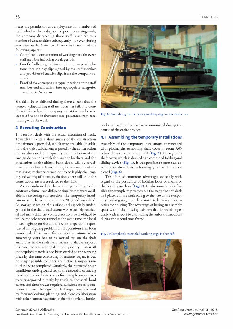
GeoResources Journal 3 | 2015
33 Tunnelling
Gotthard Base Tunnel: Planning and Executing the Installations for the Sedrun Shaft ISchöneshöfer and Ahlbrecht:
www.georesources.net
necessary permits to start employment for members of staff, who have been dispatched prior to starting work, the company dispatching those staff is subject to a number of checks either subsequently – or even during execution under Swiss law. These checks included the following aspects:
▶ Complete documentation of working time for every staff member including break periods
▶ Proof of adhering to Swiss minimum wage stipula-tions through pay slips signed by the staff member and provision of transfer slips from the company ac-count
▶ Proof of the corresponding qualifications of the staff member and allocation into appropriate categories according to Swiss law
Should it be established during these checks that the company dispatching staff members has failed to com-ply with Swiss law, the company will at the best be sub-ject to a fine and in the worst case, prevented from con-tinuing with the work.
4 Executing ConstructionThis section deals with the actual execution of work. Towards this end, a short survey of the construction time frames is provided, which were available. In addi-tion, the logistical challenges posed by the construction site are discussed. Subsequently the installation of the two guide sections with the anchor brackets and the installation of the airlock bank doors will be scruti-nized more closely. Even although the assembly of the remaining steelwork turned out to be highly challeng-ing and worthy of mention, the focus here will be on the construction measures related to the shaft.
As was indicated in the section pertaining to the contract volume, two different time frames were avail-able for executing construction. The temporary instal-lations were delivered in summer 2013 and assembled. As storage space on the surface and especially under-ground in the shaft head cavern was extremely restrict-ed and many different contract sections were obliged to utilize the sole access tunnel at the same time, the local micro-logistics on-site and the work preparation repre-sented an ongoing problem until operations had been completed. There were for instance situations when concreting work had to be carried out on the shaft enclosures in the shaft head cavern so that transport-ing concrete was accorded utmost priority. Unless all the required materials had been carried to the working place by the time concreting operations began, it was no longer possible to undertake further transports un-til these were completed. Similarly, the restricted space conditions underground led to the necessity of having to relocate stored material as for example major parts were transported directly by truck to the shaft head cavern and these trucks required sufficient room to ma-noeuvre there. The logistical challenges were mastered by forward-looking planning and close collaboration with other contract sections so that time-related bottle-
necks and reduced output were minimized during the course of the entire project.
4.1 Assembling the temporary InstallationsAssembly of the temporary installations commenced with placing the temporary shaft cover in room A03 below the access level room B04 (Fig. 2). Through this shaft cover, which is devised as a combined folding and sliding device (Fig. 4), it was possible to create an as-sembly area directly in the hoisting system with the door closed (Fig. 6).
This afforded enormous advantages especially with regard to the possibility of hoisting loads by means of the hoisting machine (Fig. 7). Furthermore, it was fea-sible for example to preassemble the stage deck by deck and place it in the shaft owing to the size of the tempo-rary working stage and the constricted access opportu-nities for hoisting. The advantage of having an assembly space within the hoisting axis revealed its worth espe-cially with respect to assembling the airlock bank doors during the second time frame.
Fig. 6: Assembling the temporary working stage on the shaft cover
Fig. 7: Completely assembled working stage in the shaft

GeoResources Journal 3 | 2015
34Tunnelling
Gotthard Base Tunnel: Planning and Executing the Installations for the Sedrun Shaft ISchöneshöfer and Ahlbrecht:
www.georesources.net
Fig. 10: Temporary working stages with drilling jigs
Fig. 9: Shaft head areaFig. 8: Shaft bottom area Source: AlpTransit Gotthard AG

GeoResources Journal 3 | 2015
35 Tunnelling
Gotthard Base Tunnel: Planning and Executing the Installations for the Sedrun Shaft ISchöneshöfer and Ahlbrecht:
www.georesources.net
4.2 Assembling the Guides and Anchor Brackets
Installing the guides and brackets was divided up into three partial steps:
▶ First stage ride, downwards: installing the brackets for the access level down to the sump (shaft bottom) (Fig. 8)
▶ Second stage ride, upwards: installing the guides from the sump to access level
▶ Third stage ride, upwards: installing the guides with preassembled brackets from the access level to the tower (Fig. 9)
For the first time a special system to reduce the amount of work was applied during the assembly of the anchor brackets. The objective was to avoid having to measure each anchor bracket individually and the application of a template. Instead the concept was to be in a position to install nine brackets all at once with the three-deck working stage set in one working position. In the pro-cess, it was not necessary to measure any of the nine brackets individually. This was made possible by fit-ting the temporary working stage with six drilling jigs (Fig. 10). The gaps between the decks were adjusted to the gaps for the brackets, namely 3.0 m from the up-per deck to the central deck and 4.5 m from the central deck of the lower one. By means of a drilling jig it was possible to drill all four anchor holes simultaneously without measuring (Fig. 11). At the same time, all
Fig. 11: Drilling the anchor holes with the drilling jigs
Fig. 12: Aligning the working stage vertically with plumb lasers (otl: off-plumb; otr: plumb)
three bracket levels could be drilled from a single work-ing stage position. This signifies that the working stage only ever required to be shifted by 12.0 m.
This system places particular challenges on the accu-racy of aligning the working stage in a drilling position. If the working stage is wrongly aligned this would lead to nine misaligned brackets. If each bracket is measured
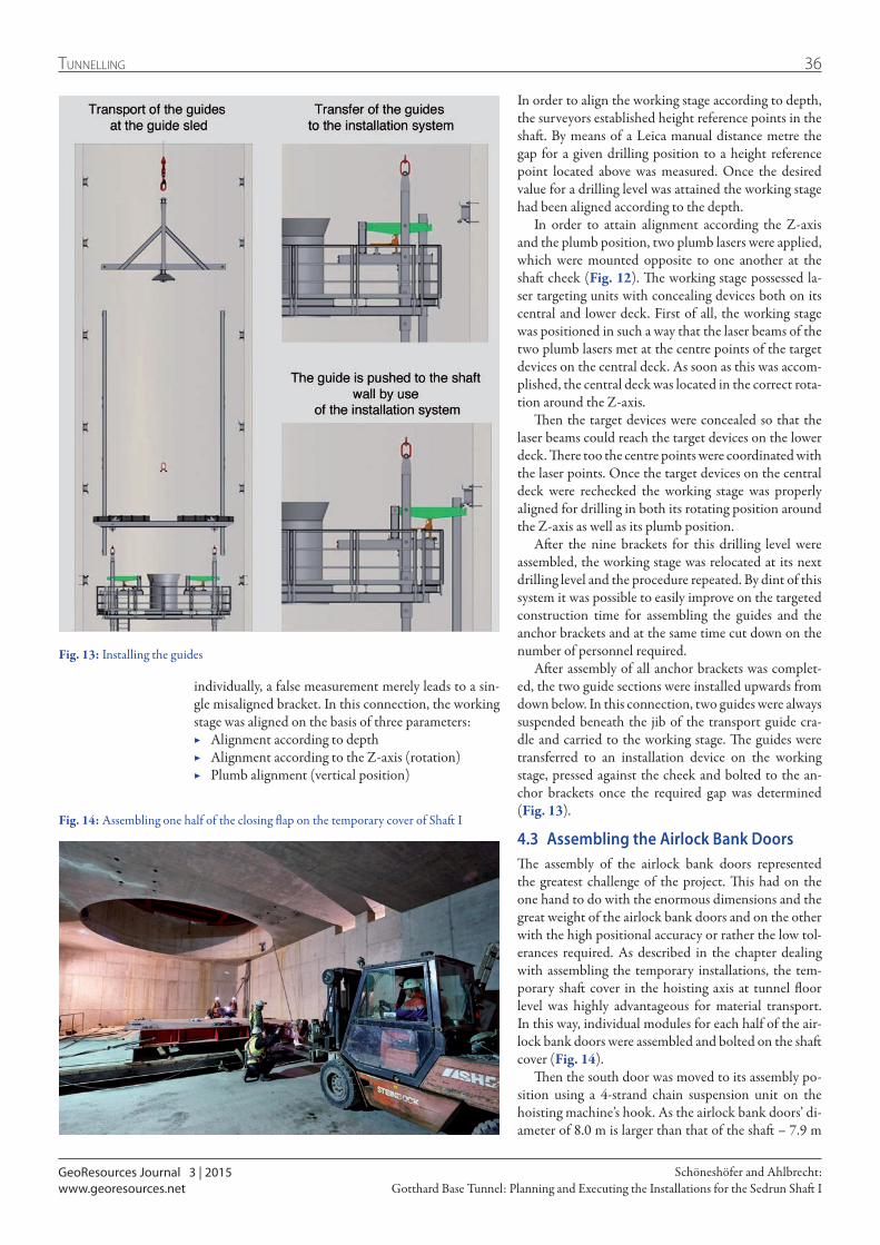
GeoResources Journal 3 | 2015
36Tunnelling
Gotthard Base Tunnel: Planning and Executing the Installations for the Sedrun Shaft ISchöneshöfer and Ahlbrecht:
www.georesources.net
In order to align the working stage according to depth, the surveyors established height reference points in the shaft. By means of a Leica manual distance metre the gap for a given drilling position to a height reference point located above was measured. Once the desired value for a drilling level was attained the working stage had been aligned according to the depth.
In order to attain alignment according the Z-axis and the plumb position, two plumb lasers were applied, which were mounted opposite to one another at the shaft cheek (Fig. 12). The working stage possessed la-ser targeting units with concealing devices both on its central and lower deck. First of all, the working stage was positioned in such a way that the laser beams of the two plumb lasers met at the centre points of the target devices on the central deck. As soon as this was accom-plished, the central deck was located in the correct rota-tion around the Z-axis.
Then the target devices were concealed so that the laser beams could reach the target devices on the lower deck. There too the centre points were coordinated with the laser points. Once the target devices on the central deck were rechecked the working stage was properly aligned for drilling in both its rotating position around the Z-axis as well as its plumb position.
After the nine brackets for this drilling level were assembled, the working stage was relocated at its next drilling level and the procedure repeated. By dint of this system it was possible to easily improve on the targeted construction time for assembling the guides and the anchor brackets and at the same time cut down on the number of personnel required.
After assembly of all anchor brackets was complet-ed, the two guide sections were installed upwards from down below. In this connection, two guides were always suspended beneath the jib of the transport guide cra-dle and carried to the working stage. The guides were transferred to an installation device on the working stage, pressed against the cheek and bolted to the an-chor brackets once the required gap was determined (Fig. 13).
4.3 Assembling the Airlock Bank DoorsThe assembly of the airlock bank doors represented the greatest challenge of the project. This had on the one hand to do with the enormous dimensions and the great weight of the airlock bank doors and on the other with the high positional accuracy or rather the low tol-erances required. As described in the chapter dealing with assembling the temporary installations, the tem-porary shaft cover in the hoisting axis at tunnel floor level was highly advantageous for material transport. In this way, individual modules for each half of the air-lock bank doors were assembled and bolted on the shaft cover (Fig. 14).
Then the south door was moved to its assembly po-sition using a 4-strand chain suspension unit on the hoisting machine’s hook. As the airlock bank doors’ di-ameter of 8.0 m is larger than that of the shaft – 7.9 m
Fig. 13: Installing the guides
Fig. 14: Assembling one half of the closing flap on the temporary cover of Shaft I
individually, a false measurement merely leads to a sin-gle misaligned bracket. In this connection, the working stage was aligned on the basis of three parameters:
▶ Alignment according to depth ▶ Alignment according to the Z-axis (rotation) ▶ Plumb alignment (vertical position)

GeoResources Journal 3 | 2015
37 Tunnelling
Gotthard Base Tunnel: Planning and Executing the Installations for the Sedrun Shaft ISchöneshöfer and Ahlbrecht:
www.georesources.net
– and furthermore a safety gap to the edge also had to be observed, the chain suspension unit was shortened at one side to place the airlock bank doors half in an inclined position (Figs. 15 to 19).
Assembly started with the south airlock bank door, as after one half was placed, the covered area of the shaft cross-section was too small to accommodate the second half. As, however, a crane was available in the south of the shaft tower, the south half was first of all tackled with the hoisting machine, temporarily bolted with the brackets and subsequently moved into a verti-cal position with the deck crane. In this way, the shaft cross-section was freed for the second half of the door and this could also be hoisted into the vertical posi-tion by means of the machine. Once both halves had reached their assembly position, the alignment work on the airlock bank doors began with accuracy of paramount importance to ensure that the previously described leakage points did not exceed the prescribed gap width.
Fig. 19: Completely assembled closing flap with the final adjustment of the gap width
Fig. 18: Bolting the flap halves with the main bracketsFig. 17: Setting on the shaft collar
Fig. 16: Positional corrections with auxiliary units and manual workFig. 15: Inclined half being hoisted

GeoResources Journal 3 | 2015
38Tunnelling
Gotthard Base Tunnel: Planning and Executing the Installations for the Sedrun Shaft ISchöneshöfer and Ahlbrecht:
www.georesources.net
portant and beneficial. In addition, it was shown that a great amount of time can be saved in executing the construction measures through technical optimizations and intricate systems, which support assembly opera-tions and which are interlinked conceptually with prac-tical processes.
Fig. 20: Assembly crew from the Deilmann-Haniel GmbH
Moritz Schöneshöfer, M.Sc.gained his master’s degree in energy and raw materials technology at the TU Clausthal in 2013.
He was involved in the Sedrun project as deputy operation site manager for the Deilmann-Haniel GmbH. Subsequently, he was engaged as project engineer to prepare for the sinking of two freezing shafts in Russia.
Contact: [email protected]
5 Conclusion
Seen overall the “Planning and Executing the Installa-tions for the Sedrun Shaft I” project involved techni-cal and organizational challenges. Admittedly, a great amount of effort was required to resolve them but at the same time all those involved enjoyed their task with new knowledge and recognitions being engendered (Fig. 20).
The project’s success clearly revealed that close and overlapping collaboration between the Technical Of-fice, which came up with the technical planning and the solution for the requirements posed on the structures, and the responsible assembly crews, was extremely im-
Dipl.-Ing. Thomas Ahlbrechtwas responsible for the Sedrun project as technical manager for Deilmann-Haniel in Dortmund. Other-wise he is in charge of shaft construction and freezing in production and permanent waste disposal sites as well as tunnelling in Germany and Europe. His duties also embrace the acquisition and processing of contracts.
Furthermore, he is responsible for recruiting staff, training apprentices as well as maintaining contacts with authorities and organizations and for German and international standardization activities.
As authorized signatory he is engaged in nu-merous internal organizational procedures with regard to coordination as well as fundamental strategic tasks on behalf of Deilmann-Haniel.
Contact: [email protected]
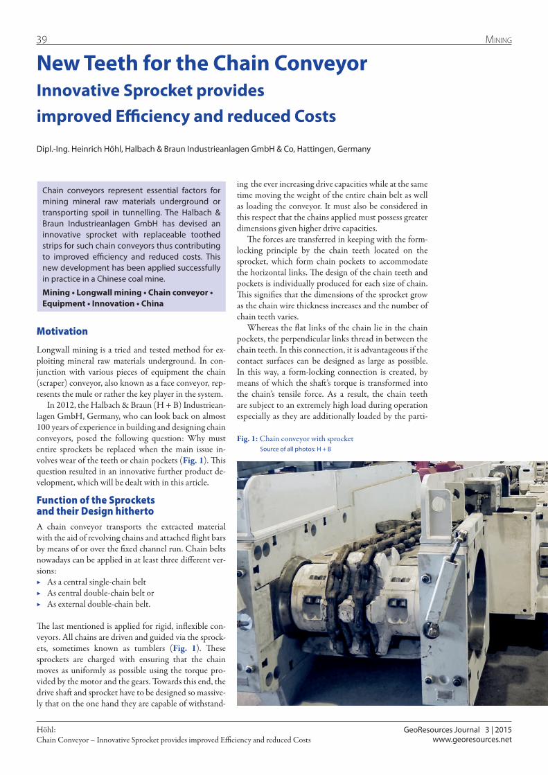
GeoResources Journal 3 | 2015
39 Mining
Chain Conveyor – Innovative Sprocket provides improved Efficiency and reduced CostsHöhl:
www.georesources.net
New Teeth for the Chain ConveyorInnovative Sprocket provides improved Efficiency and reduced Costs
Dipl.-Ing. Heinrich Höhl, Halbach & Braun Industrieanlagen GmbH & Co, Hattingen, Germany
Motivation
Longwall mining is a tried and tested method for ex-ploiting mineral raw materials underground. In con-junction with various pieces of equipment the chain (scraper) conveyor, also known as a face conveyor, rep-resents the mule or rather the key player in the system.
In 2012, the Halbach & Braun (H + B) Industriean-lagen GmbH, Germany, who can look back on almost 100 years of experience in building and designing chain conveyors, posed the following question: Why must entire sprockets be replaced when the main issue in-volves wear of the teeth or chain pockets (Fig. 1). This question resulted in an innovative further product de-velopment, which will be dealt with in this article.
Function of the Sprockets and their Design hithertoA chain conveyor transports the extracted material with the aid of revolving chains and attached flight bars by means of or over the fixed channel run. Chain belts nowadays can be applied in at least three different ver-sions:
▶ As a central single-chain belt ▶ As central double-chain belt or ▶ As external double-chain belt.
The last mentioned is applied for rigid, inflexible con-veyors. All chains are driven and guided via the sprock-ets, sometimes known as tumblers (Fig. 1). These sprockets are charged with ensuring that the chain moves as uniformly as possible using the torque pro-vided by the motor and the gears. Towards this end, the drive shaft and sprocket have to be designed so massive-ly that on the one hand they are capable of withstand-
Chain conveyors represent essential factors for mining mineral raw materials underground or transporting spoil in tunnelling. The Halbach & Braun Industrieanlagen GmbH has devised an innovative sprocket with replaceable toothed strips for such chain conveyors thus contributing to improved efficiency and reduced costs. This new development has been applied successfully in practice in a Chinese coal mine.
Mining • Longwall mining • Chain conveyor • Equipment • Innovation • China
Fig. 1: Chain conveyor with sprocket Source of all photos: H + B
ing the ever increasing drive capacities while at the same time moving the weight of the entire chain belt as well as loading the conveyor. It must also be considered in this respect that the chains applied must possess greater dimensions given higher drive capacities.
The forces are transferred in keeping with the form-locking principle by the chain teeth located on the sprocket, which form chain pockets to accommodate the horizontal links. The design of the chain teeth and pockets is individually produced for each size of chain. This signifies that the dimensions of the sprocket grow as the chain wire thickness increases and the number of chain teeth varies.
Whereas the flat links of the chain lie in the chain pockets, the perpendicular links thread in between the chain teeth. In this connection, it is advantageous if the contact surfaces can be designed as large as possible. In this way, a form-locking connection is created, by means of which the shaft’s torque is transformed into the chain’s tensile force. As a result, the chain teeth are subject to an extremely high load during operation especially as they are additionally loaded by the parti-
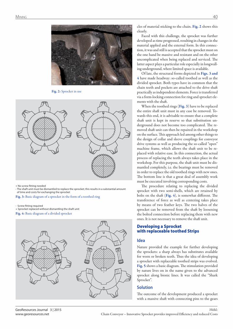
GeoResources Journal 3 | 2015
40Mining
Chain Conveyor – Innovative Sprocket provides improved Efficiency and reduced CostsHöhl:
www.georesources.net
cles of material sticking to the chain. Fig. 2 shows this clearly.
Faced with this challenge, the sprocket was further developed as time progressed, resulting in changes in the material applied and the external form. In this connec-tion, it was and still is accepted that the sprocket must on the one hand be massive and resistant and on the other uncomplicated when being replaced and serviced. The latter aspect plays a particular role especially in longwall-ing underground, where limited space is available.
Of late, the structural forms depicted in Figs. 3 and 4 have made headway: so-called toothed as well as the divided sprocket. Both types have in common that the chain teeth and pockets are attached to the drive shaft practically as independent elements. Force is transferred via a form-locking connection for ring and sprocket ele-ments with the shaft.
When the toothed rings (Fig. 3) have to be replaced the entire shaft unit must in any case be removed. To-wards this end, it is advisable to ensure that a complete shaft unit is kept in reserve so that substitution un-derground does not become too complicated. The re-moved shaft unit can then be repaired in the workshop on the surface. This approach led among other things to the design of collar and sleeve couplings for conveyor drive systems as well as producing the so-called “open” machine frame, which allows the shaft unit to be re-placed with relative ease. In this connection, the actual process of replacing the teeth always takes place in the workshop. For this purpose, the shaft unit must be dis-mantled completely, i.e. the bearings must be removed in order to replace the old toothed rings with new ones. The bottom line is that a great deal of assembly work must be executed involving corresponding costs.
The procedure relating to replacing the divided sprocket with two semi-shells, which are retained by bolts on the shaft (Fig. 4), is somewhat different. The transference of force as well as centering takes place by means of two feather keys. The two halves of the sprocket can be removed from the shaft by loosening the bolted connection before replacing them with new ones. It is not necessary to remove the shaft unit.
Developing a Sprocket with replaceable toothed Strips
IdeaNature provided the example for further developing the sprockets: a sharp always has substitutes available for worn or broken teeth. Thus the idea of developing a sprocket with replaceable toothed strips was evolved. Fig. 5 shows a basic diagram. The stimulation provided by nature lives on in the name given to the advanced sprocket along bionic lines. It was called the “Shark Sprocket”.
SolutionThe outcome of the development produced a sprocket with a massive shaft with connecting pins to the gears
Fig. 2: Sprocket in use
+ No screw fitting needed- The shaft unit must be dismantled to replace the sprocket; this results in a substantial amount
of time and costs for exchanging the sprocket
Fig. 3: Basic diagram of a sprocket in the form of a toothed ring
- Screw fitting required+ Sprocket replaced without dismantling the shaft unit
Fig. 4: Basic diagram of a divided sprocket
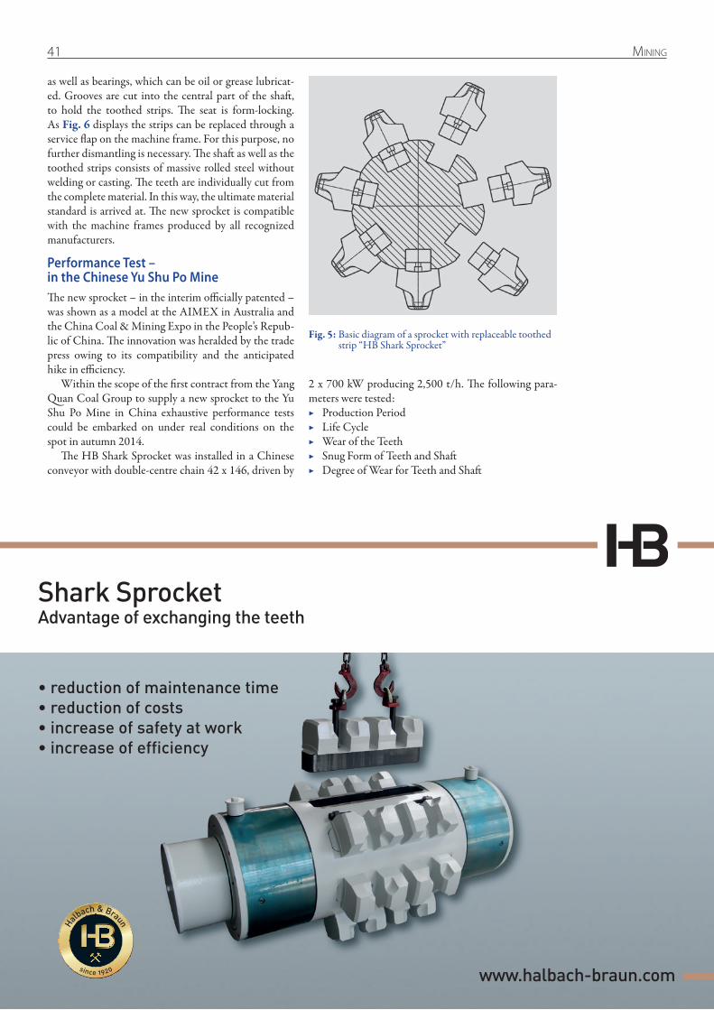
41 Mining
as well as bearings, which can be oil or grease lubricat-ed. Grooves are cut into the central part of the shaft, to hold the toothed strips. The seat is form-locking. As Fig. 6 displays the strips can be replaced through a service flap on the machine frame. For this purpose, no further dismantling is necessary. The shaft as well as the toothed strips consists of massive rolled steel without welding or casting. The teeth are individually cut from the complete material. In this way, the ultimate material standard is arrived at. The new sprocket is compatible with the machine frames produced by all recognized manufacturers.
Performance Test – in the Chinese Yu Shu Po MineThe new sprocket – in the interim officially patented – was shown as a model at the AIMEX in Australia and the China Coal & Mining Expo in the People’s Repub-lic of China. The innovation was heralded by the trade press owing to its compatibility and the anticipated hike in efficiency.
Within the scope of the first contract from the Yang Quan Coal Group to supply a new sprocket to the Yu Shu Po Mine in China exhaustive performance tests could be embarked on under real conditions on the spot in autumn 2014.
The HB Shark Sprocket was installed in a Chinese conveyor with double-centre chain 42 x 146, driven by
Shark SprocketAdvantage of exchanging the teeth
www.halbach-braun.com
• reduction of maintenance time• reduction of costs• increase of safety at work• increase of efficiency
2 x 700 kW producing 2,500 t/h. The following para-meters were tested:
▶ Production Period ▶ Life Cycle ▶ Wear of the Teeth ▶ Snug Form of Teeth and Shaft ▶ Degree of Wear for Teeth and Shaft
Fig. 5: Basic diagram of a sprocket with replaceable toothed strip “HB Shark Sprocket”

GeoResources Journal 3 | 2015
42Mining
Chain Conveyor – Innovative Sprocket provides improved Efficiency and reduced CostsHöhl:
www.georesources.net
The performance tests were executed by the local labour force in the Yang Quan Coal Group’s Yu Shu Po Coal Mine in a highly professional manner. No problems in the production process were recorded which resulted from the toothed strips. The sprocket functioned with-out causing any breakdowns; extraction work forged ahead. However, a leak in the labyrinth seal during the standard oil lubrication was established. Such leaks do, however, also occur in the case of types of sprockets used hitherto.
Given the conditions prevailing in the Yu Shu Po Mine wear on the teeth and teeth pockets was low as expected (Figs. 7 + 8). The snug fit of the replacement toothed strips turned out to be almost perfect. All measurements were within the range of production tol-erances. Problems caused by pollution or corrosion were not evident when the sprocket was removed. Damaged
Fig. 7: Visual comparison between a new toothed strip pocket (above) and a used one (below)
Fig. 8: Visual comparison between a new toothed strip pocket (otl) and a used one (otr)
Fig. 6: View of the toothed strip through the machine frame’s assembly flap
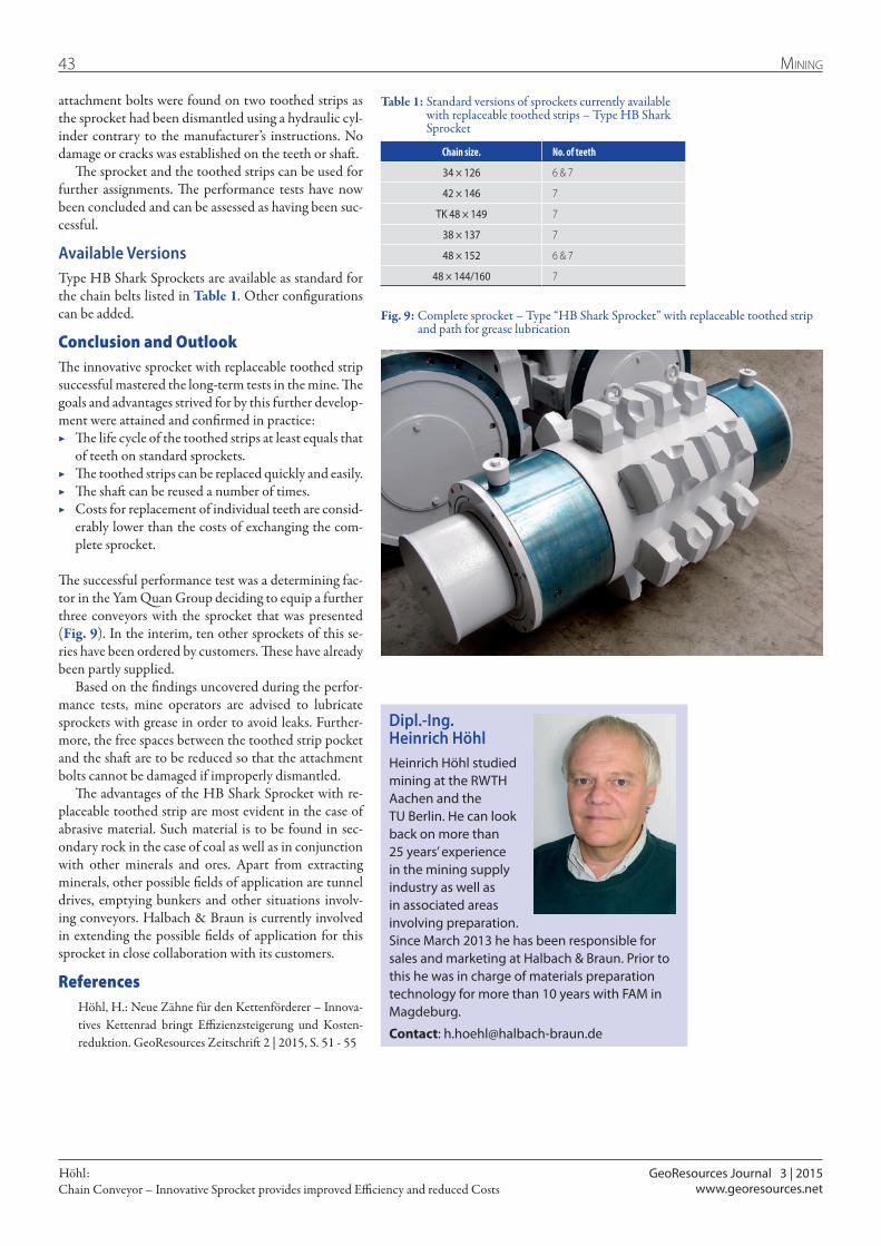
GeoResources Journal 3 | 2015
43 Mining
Chain Conveyor – Innovative Sprocket provides improved Efficiency and reduced CostsHöhl:
www.georesources.net
attachment bolts were found on two toothed strips as the sprocket had been dismantled using a hydraulic cyl-inder contrary to the manufacturer’s instructions. No damage or cracks was established on the teeth or shaft.
The sprocket and the toothed strips can be used for further assignments. The performance tests have now been concluded and can be assessed as having been suc-cessful.
Available VersionsType HB Shark Sprockets are available as standard for the chain belts listed in Table 1. Other configurations can be added.
Conclusion and Outlook The innovative sprocket with replaceable toothed strip successful mastered the long-term tests in the mine. The goals and advantages strived for by this further develop-ment were attained and confirmed in practice:
▶ The life cycle of the toothed strips at least equals that of teeth on standard sprockets.
▶ The toothed strips can be replaced quickly and easily. ▶ The shaft can be reused a number of times. ▶ Costs for replacement of individual teeth are consid-
erably lower than the costs of exchanging the com-plete sprocket.
The successful performance test was a determining fac-tor in the Yam Quan Group deciding to equip a further three conveyors with the sprocket that was presented (Fig. 9). In the interim, ten other sprockets of this se-ries have been ordered by customers. These have already been partly supplied.
Based on the findings uncovered during the perfor-mance tests, mine operators are advised to lubricate sprockets with grease in order to avoid leaks. Further-more, the free spaces between the toothed strip pocket and the shaft are to be reduced so that the attachment bolts cannot be damaged if improperly dismantled.
The advantages of the HB Shark Sprocket with re-placeable toothed strip are most evident in the case of abrasive material. Such material is to be found in sec-ondary rock in the case of coal as well as in conjunction with other minerals and ores. Apart from extracting minerals, other possible fields of application are tunnel drives, emptying bunkers and other situations involv-ing conveyors. Halbach & Braun is currently involved in extending the possible fields of application for this sprocket in close collaboration with its customers.
References Höhl, H.: Neue Zähne für den Kettenförderer – Innova-
tives Kettenrad bringt Effizienzsteigerung und Kosten-reduktion. GeoResources Zeitschrift 2 | 2015, S. 51 - 55
Dipl.-Ing. Heinrich HöhlHeinrich Höhl studied mining at the RWTH Aachen and the TU Berlin. He can look back on more than 25 years’ experience in the mining supply industry as well as in associated areas involving preparation. Since March 2013 he has been responsible for sales and marketing at Halbach & Braun. Prior to this he was in charge of materials preparation technology for more than 10 years with FAM in Magdeburg.
Contact: [email protected]
Chain size. No. of teeth
34 × 126 6 & 7
42 × 146 7
TK 48 × 149 7
38 × 137 7
48 × 152 6 & 7
48 × 144/160 7
Table 1: Standard versions of sprockets currently available with replaceable toothed strips – Type HB Shark Sprocket
Fig. 9: Complete sprocket – Type “HB Shark Sprocket” with replaceable toothed strip and path for grease lubrication
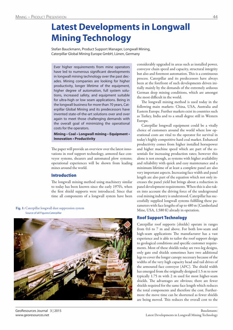
GeoResources Journal 3 | 2015
44Mining – Product Presentation
Latest Developments in Longwall Mining TechnologyBauckmann:
www.georesources.net
Latest Developments in Longwall Mining TechnologyStefan Bauckmann, Product Support Manager, Longwall Mining, Caterpillar Global Mining Europe GmbH, Lünen, Germany
The paper will provide an overview over the latest inno-vations in roof support technology, armored face con-veyor systems, shearers and automated plow systems; operational experiences will be shown from leading mines around the world.
IntroductionThe longwall mining method using machinery similar to today has been known since the early 1970’s, when the first shield supports were introduced. Since that time all components of a longwall system have been
Ever higher requirements from mine operators have led to numerous significant developments in longwall mining technology over the past dec-ades. Mining companies are looking for higher productivity, longer lifetime of the equipment, higher degree of automation, full system solu-tions, increased safety, and equipment suitable for ultra-high or low seam applications. Being in the longwall business for more than 70 years, Cat-erpillar Global Mining and its predecessors have invented state-of-the-art solutions over and over again to meet those challenging demands with the overall goal of minimizing the operational costs for the operators.
Mining • Coal • Longwall mining • Equipment • Innovation • Productivity
Fig. 1: Caterpillar longwall dust suppression system Source of all Figures:Caterpillar
considerably upgraded in areas such as installed power, conveyor chain speed and capacity, structural integrity but also and foremost automation. This is a continuous process. Caterpillar and its predecessors have always been at the forefront of such developments driven ini-tially mainly by the demands of the extremely arduous German deep mining conditions, which are amongst the most difficult in the world.
The longwall mining method is used today in the following main markets: China, USA, Australia and Eastern Europe. Further markets exist in countries such as Turkey, India and to a small degree still in Western Europe.
Caterpillar longwall equipment could be a vitally choice of customers around the world where low op-erational costs are vital to the operator for survival in today’s highly competitive hard coal market. Enhanced productivity comes from higher installed horsepower and higher machine speed which are part of the es-sentials for increasing production rates; however this alone is not enough, as systems with higher availability and reliability with quick and easy maintenance and a minimum lifetime of at least a complete panel are also very important aspects. Increasing face width and panel length are also part of the equation which not only in-creases the panel yield but brings about a reduction in panel development requirements. When this is also tak-en into account the driving force of the underground coal mining industry is understood. Caterpillar has suc-cessfully supplied longwall systems fulfilling these pa-rameters with face lengths of up to 480 m (Cumberland Mine, USA, 1,580 ft) already in operation.
Roof Support TechnologyCaterpillar roof supports (shields) operate in ranges from 0.6 to 7 m and above. For both low-seam and high-seam applications The manufacturer has a vast experience and is able to tailor the roof support design to geological conditions and specific customer require-ments. Most of these shields today are two-leg designs, only gate end shields sometimes have two additional legs to cover the longer canopy necessary because of the widths of the very high capacity head and tail drives of the armoured face conveyor (AFC). The shield width has emerged from the originally designed 1.5 m to now typically 1.75 m with 2 m used for most higher-seam shields. The advantages are obvious; there are fewer shields required for the same face length which reduces the total components and therefore the cost. Further-more the move time can be shortened as fewer shields are being moved. This reduces the overall cost to the
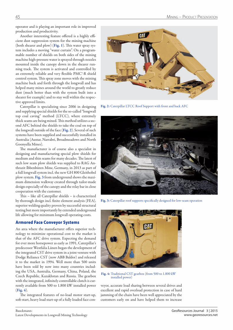
GeoResources Journal 3 | 2015
45 Mining – Product Presentation
Latest Developments in Longwall Mining TechnologyBauckmann:
www.georesources.net
operator and is playing an important role in improved production and productivity.
Another interesting feature offered is a highly effi-cient dust suppression system for the mining machine (both shearer and plow) (Fig. 1). This water spray sys-tem includes a moving “water curtain”. On a program-mable number of shields on both sides of the mining machine high-pressure water is sprayed through nozzles mounted inside the canopy down in the shearer run-ning track. The system is activated and controlled by an extremely reliable and very flexible PMC®-R shield control system. This spray zone moves with the mining machine back and forth through the longwall and has helped many mines around the world to greatly reduce dust (much better than with the system built into a shearer for example) and to stay well within the respec-tive approved limits.
Caterpillar is specializing since 2006 in designing and supplying special shields for the so-called “longwall top coal caving” method (LTCC), where extremely thick seams are being mined. This method utilizes a sec-ond AFC behind the shields to take the coal on top of the longwall outside of the face (Fig. 2). Several of such systems have been supplied and successfully installed in Australia (Austar, Narrabri, Broadmeadows and North Goonyella Mines).
The manufacturer is of course also a specialist in designing and manufacturing special plow shields for medium and thin seams for many decades. The latest of such low seam plow shields was supplied to RAG An-thrazit Ibbenbüren Mine, Germany, in 2013 as part of a full longwall system incl. the new GH 800 Gleithobel plow system. Fig. 3 from underground shows the maxi-mum dimension walkway created through tailor-made design especially of the canopy and the relay bar in close cooperation with the customer.
This – like all Caterpillar shields – is characterized by thorough design incl. finite element analysis (FEA), superior welding quality proven by successful structural testing but more importantly by extended underground life allowing for minimum longwall operating costs.
Armored Face Conveyor SystemsAn area where the manufacturer offers superior tech-nology to minimize operational cost to the market is that of the AFC drive system. Expecting the demand for ever more horsepower as early as 1991, Caterpillar’s predecessor Westfalia Lünen began the development of the integrated CST drive system in a joint venture with Dodge Reliance CST (now ABB Baldor) and released it to the market in 1994. Well more than 500 units have been sold by now into many countries includ-ing the USA, Australia, Germany, China, Poland, the Czech Republic, Kazakhstan and Russia. The gearbox with the integrated, infinitely controllable clutch is cur-rently available from 500 to 1.800 kW installed power (Fig. 4).
The integrated features of no-load motor start-up, soft-start, heavy load start-up of a fully loaded face con-
Fig. 2: Caterpillar LTCC Roof Support with front and back AFC
Fig. 4: Traditional CST gearbox (from 500 to 1.800 kW installed power)
Fig. 3: Caterpillar roof supports specifically designed for low-seam operation
veyor, accurate load sharing between several drives and excellent and rapid overload protection in case of hard jamming of the chain have been well appreciated by the customers early on and have helped them to increase

GeoResources Journal 3 | 2015
46Mining – Product Presentation
Latest Developments in Longwall Mining TechnologyBauckmann:
www.georesources.net
their running time and thus their productivity. The CST drive system (CST = controlled start transmis-sion) is the only available system where full break-down torque (BDT) is applied at all drives from all motors at the same time (synchronized heavy-load start-up). Essentially the CST allows a staggered motor start-up at whatever sequence as the AFC start-up sequence is performed totally independent of this. Normally the tail drive is engaged first to pull away any slack chain; as soon as that has happened all drives apply increas-ing torque simultaneously. Thus all drive will reach full BDT at the same time if this is required by the AFC. This is achieved through the intelligent and extremely fast realtime drive control system PMC-D. Therefore the BDT for the motors of a CST drive system will al-ways be less than with any other drive system. Further-more, as the CST couplings are only engaged when all motors are at full speed, there is an additional amount of kinetic energy which is used to start the AFC.
One slight disadvantage of the CST has always been the ability to be operated at lower speed. This is due to the fact that the cooling oil pumps (as well as the high-pressure pump for clutch operation) are driven by the main motor. If the main motor is slowed down, the cooling oil flow will be reduced exponentially. There-fore the CST would overheat under load. A revised ver-
Fig. 6: New EL3000 shearer during final testing at Caterpillar in Lünen
Fig. 5: Upgraded version of the CST gearbox with integrated pump motor
sion of the CST gearbox released in 2012 now offers a built-in electrical pump motor which is independent of the main AFC motor and thus allows infinitely lower AFC speed (Fig. 5).
The first of such innovative drive systems is in suc-cessful operation at Bogdanka Mine in Poland since 2012 in a complete plow system in conjunction with a VFD drive to operate and control the speed of the face conveyor and the plow motors.
ShearersCaterpillar has upgraded its Electra fleet of shearers over the last few years with the clear goal of further increasing reliability and availability while utilizing a new, common electronic platform to build on the lead-ing automation capabilities. The proven concept of a one-piece mainframe (can be designed as a three-piece mainframe for customers with transportation limita-tions) has been maintained. While this offers maximum protection to all major shearer components, a further advantage is that downtime due to difficult geological conditions is minimized as other shearers in such ardu-ous conditions are more frequently damaged.
The first next-generation EL3000 shearer went to work in 2012 in Australia’s Narrabri mine as part of a complete LTCC system (Fig. 6). Several more shear-ers of the same size are now in operation (mainly in Australia) as well as the smaller EL1000 and EL2000 machines. All own a common, newly developed control hard- and software, allowing more automation features while making maintenance and fault-finding easier than with the older electronics.
Automated Plow SystemsCaterpillar plow systems have been successfully used since the early 1940’s. This proven technology in its now fully automated version is installed in numerous faces not only in Germany but also in the USA, China, Kazakhstan, the Ukraine, Czech Republic, Mexico and Poland. Since the mid 1990’s, the Caterpillar plow systems feature an installed power for cutting of up to 2 x 400 kW at a plow speed of up to 3 m/s. Seams of any hardness are being mined, the maximum face length ap-plied to-date underground is 400 m wide and the maxi-
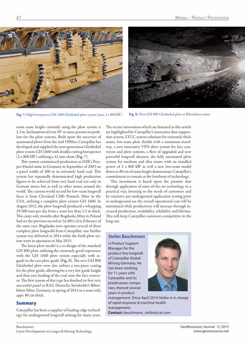
GeoResources Journal 3 | 2015
47 Mining – Product Presentation
Latest Developments in Longwall Mining TechnologyBauckmann:
www.georesources.net
mum seam height currently using the plow system is 2,3 m. Inclinations of even 50° or more present no prob-lem for the plow systems. Built upon the successes of automated plows from the mid 1990ies, Caterpillar has developed and supplied the next-generation Gleithobel plow system GH 1600 with double cutting horsepower (2 x 800 kW) utilizing a 42 mm chain (Fig. 7).
This system commenced production at DSK’s Pros-per-Haniel mine in Germany in September of 2003 on a panel width of 400 m in extremely hard coal. This system has repeatedly demonstrated high production figures to be achieved from very hard coal not only in German mines but as well in other mines around the world. The current world record for low-seam longwall faces is from Cleveland Cliffs Pinnacle Mine in the USA, utilizing a complete plow system GH 1600. In August 2012, the plow longwall produced a whopping 29.500 tons per day from a seam less than 1,5 m thick. This came only months after Bogdanka Mine in Poland had set the previous record at 24.400 t/d in February of the same year. Bogdanka now operates several of these complete plow longwalls from Caterpillar; one further system was delivered in 2014 while the forth plow sys-tem went in operation in May 2015.
The latest plow model is a re-design of the standard GH 800 plow, utilizing the extremely good experience with the GH 1600 plow system especially with re-gards to the cast plow guide (Fig. 8). The new GH 800 Gleithobel plow now also utilizes a one-piece casting for the plow guide, allowing for a very low guide height and thus easy loading of the coal onto the face convey-or. The first system of this type has finished its first very successful panel at RAG Deutsche Steinkohle’s Ibben-büren Mine, Germany, in spring of 2014 in a seam only appr. 80 cm thick.
SummaryCaterpillar has been a supplier of leading-edge technol-ogy for underground longwall mining for many years.
Fig. 7: High-horsepower GH 1600 Gleithobel plow system (max. 2 x 800 kW)
The recent innovations which are featured in this article are highlighted by Caterpillar’s innovative dust suppres-sion system, LTCC system solutions for extremely thick seams, low-seam plow shields with a maximum travel-way, a new innovative VFD drive system for face con-veyors and plow systems, a fleet of upgraded and new powerful longwall shearers, the fully automated plow system for medium and thin seams with an installed power of 2 x 800 kW as well a new low-seam model down to 80 cm of seam height demonstrate Caterpillar’s commitment to remain at the forefront of technology.
This investment is based upon the premise that through application of state-of-the-art technology in a practical way, listening to the needs of customers and by extensive pre-underground application testing prior to underground use the overall operational cost will be minimized while productivity will increase through in-creased production, availability, reliability and lifetime. This will keep Caterpillar customers competitive in the long run.
Stefan Bauckmannis Product Support Manager for the product line longwall of Caterpillar Global Mining Germany. He has been working for 11 years with Caterpillar and its predecessor compa-nies, thereof several years in product management. Since April 2014 Stefan is in charge of rapid response & machine health management. Contact: [email protected]
Fig. 8: New GH 800 Gleithobel plow at Ibbenbüren mine
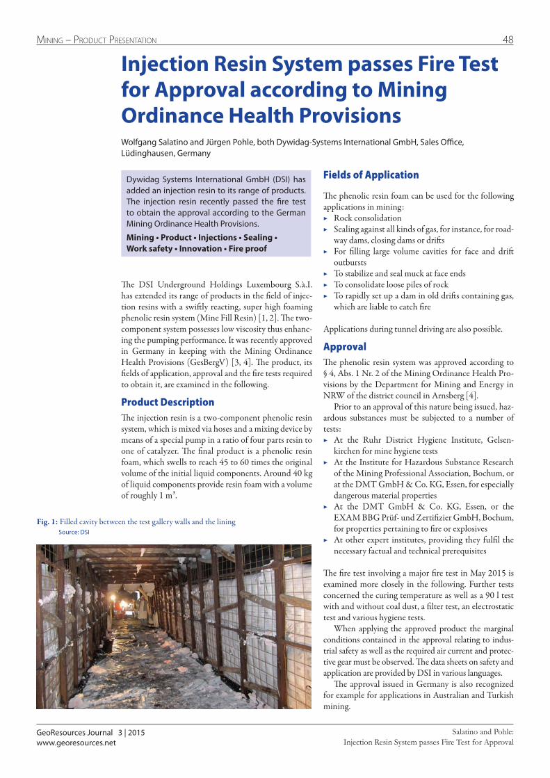
GeoResources Journal 3 | 2015
48Mining – Product Presentation
Injection Resin System passes Fire Test for ApprovalSalatino and Pohle:
www.georesources.net
Injection Resin System passes Fire Test for Approval according to Mining Ordinance Health ProvisionsWolfgang Salatino and Jürgen Pohle, both Dywidag-Systems International GmbH, Sales Office, Lüdinghausen, Germany
The DSI Underground Holdings Luxembourg S.à.I. has extended its range of products in the field of injec-tion resins with a swiftly reacting, super high foaming phenolic resin system (Mine Fill Resin) [1, 2]. The two-component system possesses low viscosity thus enhanc-ing the pumping performance. It was recently approved in Germany in keeping with the Mining Ordinance Health Provisions (GesBergV) [3, 4]. The product, its fields of application, approval and the fire tests required to obtain it, are examined in the following.
Product DescriptionThe injection resin is a two-component phenolic resin system, which is mixed via hoses and a mixing device by means of a special pump in a ratio of four parts resin to one of catalyzer. The final product is a phenolic resin foam, which swells to reach 45 to 60 times the original volume of the initial liquid components. Around 40 kg of liquid components provide resin foam with a volume of roughly 1 m³.
Dywidag Systems International GmbH (DSI) has added an injection resin to its range of products. The injection resin recently passed the fire test to obtain the approval according to the German Mining Ordinance Health Provisions.
Mining • Product • Injections • Sealing • Work safety • Innovation • Fire proof
Fields of Application
The phenolic resin foam can be used for the following applications in mining:
▶ Rock consolidation ▶ Sealing against all kinds of gas, for instance, for road-
way dams, closing dams or drifts ▶ For filling large volume cavities for face and drift
outbursts ▶ To stabilize and seal muck at face ends ▶ To consolidate loose piles of rock ▶ To rapidly set up a dam in old drifts containing gas,
which are liable to catch fire
Applications during tunnel driving are also possible.
ApprovalThe phenolic resin system was approved according to § 4, Abs. 1 Nr. 2 of the Mining Ordinance Health Pro-visions by the Department for Mining and Energy in NRW of the district council in Arnsberg [4].
Prior to an approval of this nature being issued, haz-ardous substances must be subjected to a number of tests:
▶ At the Ruhr District Hygiene Institute, Gelsen-kirchen for mine hygiene tests
▶ At the Institute for Hazardous Substance Research of the Mining Professional Association, Bochum, or at the DMT GmbH & Co. KG, Essen, for especially dangerous material properties
▶ At the DMT GmbH & Co. KG, Essen, or the EXAM BBG Prüf- und Zertifizier GmbH, Bochum, for properties pertaining to fire or explosives
▶ At other expert institutes, providing they fulfil the necessary factual and technical prerequisites
The fire test involving a major fire test in May 2015 is examined more closely in the following. Further tests concerned the curing temperature as well as a 90 l test with and without coal dust, a filter test, an electrostatic test and various hygiene tests.
When applying the approved product the marginal conditions contained in the approval relating to indus-trial safety as well as the required air current and protec-tive gear must be observed. The data sheets on safety and application are provided by DSI in various languages.
The approval issued in Germany is also recognized for example for applications in Australian and Turkish mining.
Fig. 1: Filled cavity between the test gallery walls and the lining Source: DSI

GeoResources Journal 3 | 2015
49 Mining – Product Presentation
Injection Resin System passes Fire Test for ApprovalSalatino and Pohle:
www.georesources.net
References
[1] DSI: Technical Data Sheet Mine-Fill Component A and Component B. May 2015
[2] DSI: Safety Data Sheets Mine-Fill A and Mine-Fill B. June 2015
[3] Bundesministerium der Justiz und für Verbraucherschutz: Bergverordnung zum gesundheitlichen Schutz der Be-schäftigten (Gesundheitsschutz-Bergverordnung - Ges-BergV). 31.07. 1991 (BGBl. I S. 1751), zuletzt geändert am 26.11.2010 (BGBl. I S. 1643)
[4] Bezirksregierung Arnsberg: Zulassungsbescheid für Zweikomponenten-Phenolharzsystem Mine Fill aufgr-und § 4 Abs. 1 Nr. 2 der GesBergV in aktuell gültiger Fas-sung. 18. August 2015
Fig. 2: Pump for injecting the phenolic resin foam Source: DSI
Fire Test
The fire test for the phenolic resin system was carried out in conjunction with the joint test conditions of the German Regional Mining Authority for general approval in keeping with § 4 in connection with Ap-pendix 5 of the GesBergV at the DMT GmbH & Co. KG’s test lab.
Preparations for the major test in a special gallery at the test lab required several days. Once a 13 m long section of the gallery had been prepared (Fig. 1), DSI and DMT installed tubular films and filled the cavities between the gallery walls and lining with the phenolic resins (Figs. 1 + 2). The filling process took almost three days. Once the foams had been installed the reinforce-ment matting and the tubular films had to be removed. In addition, the necessary measuring instruments were installed and the synthetic resins had to dry completely.
A fire seat was set up according to exact specifica-tions for the fire test (Fig. 3). The measuring units installed in the tunnel monitored the temperatures as well as the gas emissions. During the fire two specially trained fire officers stayed in the tunnel. The complete test was supervised from a control room on the surface (Fig. 4).
The fire reached temperatures exceeding 800 °C and was monitored overnight (Fig. 5). During the entire test the highest temperature measured for the phenolic resin foam body amounted to only 99.47 °C – a value, which is substantially below the maximum permitted temperature of 150 °C.
After a 24-h cooling period for the test set-up the phenolic resin foam body was cut open. It revealed a fine-pored, homogeneous structure and displayed no indications of carbonization. The phenolic resin system fulfilled the posed requirements and passed the fire test.
ConclusionDSI has passed the fire test in keeping with currently valid GesBergV requirements with its new phenolic resin system and possesses technical approval in accor-dance with GesBergV. The injection resin has already been successfully applied in various countries such as Australia, Russia and the UK.
Fig. 3: The fire source Source: DMT GmbH & Co. KG
Fig. 4: Control room for the fire test Source: DMT GmbH & Co. KG
Fig. 5: The fire Source: DMT GmbH & Co. KG
Wolfgang SalatinoHead of Sale of Mining Chemicals Europe
Contact: [email protected]
CFT is a system provider for dedusting andventilation technology. From project planningand design to the point of assembly and services.
CFT offers you high-quality and innovativesolutions available from one source in cooperationwith reputable partners.
Wengeler & Kalthoff
www.we-ka.de
MINING. TUNNELLING. CONSTRUCTION INDUSTRY. STEELMAKING.
Wengeler & Kalthoff produce one-off and series-manufactured boring and hammer drilling tools forspecial assignments and to any customer specification.
Tool functionality and long service life are ensuredthanks to a wide range of machining and finishing processes that deliver the required hardness, shapeand toughness for a cost effective and high performance result every time.
Tools for drilling and rockbolting
Wengeler & Kalthoff Hammerwerke GmbH & Co. KGWittener Straße 16458456 WittenGermany
Phone: +49 (23 24) 93 47-0Fax: +49 (23 24) 93 47-44E-Mail: [email protected]
Tools for drilling and rockbolting
We sink shafts.Any mineral. Any geology. Anywhere.For more than 125 years we have safely and successfully sunk more than 500 shafts with a depth of over 230,000 m.
We are a member of The Redpath Group, operating on all five continents and belonging to the world market leaders in the field of mine contracting and construction.
We provide our customers with a complete range of services from design and engineering to construction, maintenance, reconstruction and rehabilitation.
Contact us with your shaft-related inquiries.
DEILMANN-HANIEL GmbH
44317 Dortmund/Germany Tel +49 231 2891 395 Fax +49 231 2891 352
www.deilmann-haniel.com
Free
ze s
haft
Ura
lkal
i 1, U
st-J
aiw
a, R
ussi
a

bauma mining Special
In alphabetic order and provided
with keywords, the bauma
mining Special pilots you through
an exhibition of superlatives.
Order possible from now on.
Early Bird-discount til 23 Dec 2015!
Print documents til 20 Jan 2016.
Interested in participating?Send a short email to: [email protected]
and we`ll get back soon with all necessary information.
Portal for Mining, Tunnelling, Geotechnics and Equipment
Company portrait - prototype
bauma mining special 1 | 2016
www.georesources.net
GeoResources Verlag
We make the underground the foreground
Member-
ship:
GeoResources provides a portal and a jour-
nal on the topics of mining, tunnelling,
geotechnics and equipment.
You ask for news in the branch? New
order intakes? New figures from a stock
exchange noticed supplier? New peo-
ple? New positions? New products?
News about projects? The online portal
www.georesources.net has the answer. The
latest information is distributed on a day-
to-day basis. More than 30.000 profession-
als from more than 180 countries attend
the website every month.
Georesources Verlag wishes to set up
links between classical readers of printed
articles and the computer generation. In a
somewhat unconventional manner GeoRe-
sources combines the portal and the jour-
nal as well as geotechnics and mining.
The quarterly GeoResources Journal
contains detailed articles and papers on
what happens on the big building sites and
in raw materials production all over the
world as well as in the R&D divisions and
the relevant universities.
The GeoResources Journal is available
quarterly as a download on www.geore-
sources.net in English and German lan-
guage as well as a printed version.
Providers and service suppliers in the
relevant industries find with www.geore-
sources.net and GeoResources Journal a
stage for their advertisements and ban-
ners.
Contact: Manfred König
Address 1: Oleanderweg 12
Address 2:
Zip code: 47228
City: Duisburg
Country: Germany
Phone: +49 172 244 16 16
Email: [email protected]
Internet: www.georesources.net
Branches/Products/Services
Mining • Tunnelling • Geotechnics • Equipment • Communication • Public Relations
bauma-
booth:
Copies of GeoResources
Journals available
at C2.224 (c/o VDMA)
bauma 2016
Bergbaumaschinen
Baumaschinen
Innovation
Interview
Projekte
Zulieferer
Dienstleister
VDMA Mining
FABMünchen
International
GeoResources Verlag
ISSN | Digital 2364-0278 • Druck 2364-8414
www.georesources.net
Zeitschrift
Fachzeitschrift für Ressourcen, Bergbau, Geotechnik, Tunnelbau und Equipment01 | 2016
bauma Spezial
www.GeoResources.net
The compass for the bauma mining visitor.
with support of VDMA mining
Phot
o: fo
tolia
.dav
is
MK_Anzeige_bauma_Endvers._engl.indd 1 24.11.15 12:34