Embed Size (px)
Citation preview


J. Thermal Analysis, Vol. 37, pp. 1633-1656 (1991) page-2-
1. Introduction
Thermal behaviour investigations of organic and inorganic materials played a major role in my scientificcareer. Thirty years ago, when I introduced DTA as a new tool for understanding the structural behaviour ofpolyurethanes and oligo-urethanes, I had to build my own equipment. The bibliography of my Dr. rer. natThesis contained only two references dealing with the differential thermal analysis of organic polymers [1].Today, state-of-the-art materials characterization is routinely carried out using thermal analysis. In theaftermath of various catastrophic fires in France in 1970/73, it seemed useful to carry out research into newheat-resistant materials in the form of non-flammable and non-combustible «plastic materials». Thegeopolymers are the result of this research. My work and the developments carried out in the laboratories ofthe private research company CORDI SA since 1972, are on the creation of materials designed initially forstate-of-the-art technology, and now for the whole industry, with spin-off in other fields such as the arts andarchaeometry [2].
In 1978, looking for inorganic-polymer technologies, I was struck by the similar hydrothermal conditionswhich were controlling the synthesis of organic phenolic plastics on one hand, and of mineral feldspathoidsand zeolites on the other hand. Both syntheses require high pH values, concentrated alkali, atmosphericpressure, and thermoset at temperatures below 150°C. However, zeolites were synthesized exclusively foruse in the catalysis of organic compounds [3][4]. Study of the literature and of the patent data-banks dem-onstrates that, before 1978, the idea of using this mineral chemistry for the development of a new family ofmineral binders and mineral polymers, had been totally neglected.
The amorphous to semi-cristalline three dimensional silico-aluminate structures were christened«geopolymers» of the types [5]:
Poly(sialate) (-Si-O-Al-O-),Poly(sialate-siloxo) (-Si-O-Al-O-Si-O-),Poly(sialate-disiloxo) (-Si-O-Al-O-Si-O-Si-O-) .
Apart from Applied Archaeological Sciences (research carried out at Barry University, Miami, Florida), theaim of our R. & D. long term program was not academic [6]. This explains why very little scientific litera-ture is available on the subject of geopolymers. The majority of references disclosing this application ofmineralogy belongs to the patent-literature. The applications of this new family of mineral binders havebeen tested in pilot plants, in the E.E.C. and in the USA. A good many have reached the industrial stage.LONE STAR INDUSTRIES (USA): new class of special cements and blended cements: PYRAMENT*cements; HÜLS TROISDORF AG (Germany): building products and industrial uses, TROLIT* binders[7]; GEOPOLYMERE Sarl (France): advanced mineral binders for severe environments, temperature sta-ble resins for moulds and forms, GEOPOLYMITE* binders, ceramic-ceramic compositesGEOPOLYCERAM* [8][9][10].
2. Terminology
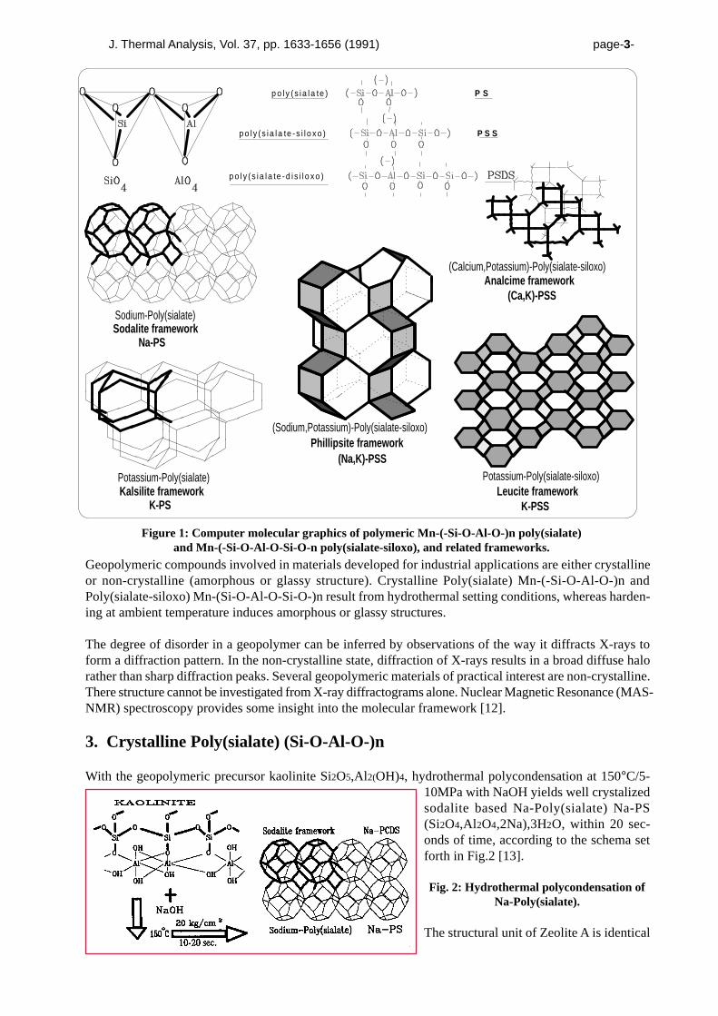
For the chemical designation of geopolymers based on silico-aluminates, poly(sialate) was suggested. Sialateis an abreviation for silicon-oxo-aluminate. The sialate network consists of SiO4 and AlO4 tetrahedra linkedalternately by sharing all the oxygens. Positive ions (Na+, K+, Li+, Ca++, Ba++, NH4+, H3O+) must bepresent in the framework cavities to balance the negative charge of Al3++ in IV-fold coordination.Poly(sialates) have this empirical formula: Mn{-(SiO2)z-AlO2}n, wH2Owherein M is a cation such as potassium, sodium or calcium, and «n» is a degree of polycondensation; «z»is 1, 2, 3 [11]. Poly(sialates) are chain and ring polymers with Si4+ and Al3+ in IV-fold coordination withoxygen and range from amorphous to semi-cristalline. Some related frameworks are displayed in Fig.1.
J. Thermal Analysis, Vol. 37, pp. 1633-1656 (1991) page-3-
Geopolymeric compounds involved in materials developed for industrial applications are either crystallineor non-crystalline (amorphous or glassy structure). Crystalline Poly(sialate) Mn-(-Si-O-Al-O-)n andPoly(sialate-siloxo) Mn-(Si-O-Al-O-Si-O-)n result from hydrothermal setting conditions, whereas harden-ing at ambient temperature induces amorphous or glassy structures.
The degree of disorder in a geopolymer can be inferred by observations of the way it diffracts X-rays toform a diffraction pattern. In the non-crystalline state, diffraction of X-rays results in a broad diffuse halorather than sharp diffraction peaks. Several geopolymeric materials of practical interest are non-crystalline.There structure cannot be investigated from X-ray diffractograms alone. Nuclear Magnetic Resonance (MAS-NMR) spectroscopy provides some insight into the molecular framework [12].
3. Crystalline Poly(sialate) (Si-O-Al-O-)n
With the geopolymeric precursor kaolinite Si2O5,Al2(OH)4, hydrothermal polycondensation at 150°C/5-10MPa with NaOH yields well crystalizedsodalite based Na-Poly(sialate) Na-PS(Si2O4,Al2O4,2Na),3H2O, within 20 sec-onds of time, according to the schema setforth in Fig.2 [13].
Fig. 2: Hydrothermal polycondensation ofNa-Poly(sialate).
The structural unit of Zeolite A is identical
Figure 1: Computer molecular graphics of polymeric Mn-(-Si-O-Al-O-)n poly(sialate)and Mn-(-Si-O-Al-O-Si-O-n poly(sialate-siloxo), and related frameworks.
Na-PS
Sodium-Poly(sialate)Sodalite framework
Kalsilite frameworkPotassium-Poly(sialate)
K-PS
Analcime framework(Ca,K)-PSS
Leucite frameworkK-PSS
Phillipsite framework
(Calcium,Potassium)-Poly(sialate-siloxo)
(Sodium,Potassium)-Poly(sialate-siloxo)
(Na,K)-PSSPotassium-Poly(sialate-siloxo)
p o l y (s i a l a te -d i s i l o x o )
p o l y (s i a l a te -s i l o x o ) P S S
p o l y (s i a l a te ) P S

J. Thermal Analysis, Vol. 37, pp. 1633-1656 (1991) page-4-
with that of Na-Poly(sialate) and is based on the sodalite cage (Fig.3). The 3-dimensional framework evolvesfrom the polycondensation of the dimer: cyclo-di-sialate (CDS). For Zeolite A the primary condensationunit is the tetramer cyclo-tetra-sialate which is formed in the solution prior to crystallization. The geopolymerK-PS, potassium-poly(sialate) results from the polycondensation with KOH instead of NaOH.
Fig. 3: Structural frameworks of Zeolite A and Na-Poly(sialate)
In 1976, the extremely reactive geopolymeric precursor alumino-silicate oxide (Si2O5,Al2O2) was used inthe manufacture of panels and tiles [14]. Yet the experimental conditions which control the hardening of theceramic paste, 150°C/15 MPa, do not favour any formation of single crystals, as is generally the case for thepreparation of zeolitic species. On the contrary, one obtains a hard microporous ceramic body. X-ray dif-fraction patterns (Fig.4) suggest a structure compris-ing a mixture of Na-PS and some Zeolite A, for short-time reaction (10-15 min). With longer reaction time,45-60 min., only the denser Na-PS is formed.
Fig. 4: X-ray diffractograms for ceramic bodiesobtained with alumino-silicate oxide (Si2O5,Al2O2);increasing reaction time. Typical d-values for Zeolite
A are shown only by the 10 min. reaction-timepattern.
4. Amorphous Poly(sialate-siloxo) (Si-O-Al-O-Si-O)n,(Na,K)-PSS, (Ca,K)-PSS and K-PSS
It is known that the mechanism of formation of crystalline zeolitic species with the ratio Si/Al>2 requiresthe silico-aluminate gels to be crystallized in a closed hydrothermal system at temperatures varying gener-ally from room temperature to about 175°C. In some cases, higher temperatures to 300°C are used. Thepressure is generally the autogenous pressure ap-proximately equivalent to the saturated vapour pres-sure (svp) of water at the temperature designated.The time required for crystallization varies from afew hours to several days. Aging time at room tem-perature is 24 hours; crystallization time at 100°Cfrom 50 to 100 hours [4]. For the K2O-Al2O3-SiO2system, crystallization temperatures range from150°C to 230°C. See Fig.5 [15].
Fig. 5: Crystallization temperature ranges for K2O-Al2O3-SiO2 system adapted from [15].
Yet geopolymer binders generally do not implement these hydrothermal conditions. However, in somecases, hydrothermal conditions may be found in the fabrication process of special fibre reinforced compos-ites which requires a relatively higher setting temperature in the 150°-180°C range. One hardening mecha-nism among others involves the chemical reaction of geopolymeric precursors such as alumino-silicateoxides (Al3+ in IV-fold coordination) with alkali polysilicates yielding polymeric Si-O-Al bonds. In order

J. Thermal Analysis, Vol. 37, pp. 1633-1656 (1991) page-5-
to emphasize the IV fold coordination of Al we usually write (Si2O5,Al2O2)n for these particular alumino-silicate oxides instead of (2SiO2,Al2O3) [16].
The fabrication of (Si2O5,Al 2O2)n is carried out (a) by calcining alumino-silicate hydroxides(Si2O5,Al2(OH)4), or (b) by condensation of SiO and Al2O vapors: (a) 2(Si2O5,Al2(OH)4) → 2 (Si2O5,Al2O2)n+ 4H2O (b) 4SiO (vapor) + 2Al2O (vapor) + 4O2 → (Si2O5,Al2O2)n with also production of: 2SiO + O2 → 2SiO2 (Condensed Silica Fume) Al2O + O2 → Al2O3 (Corundum)Geopolymerisation is exothermic and can be schematised as follows. It may be considered as the result ofthe polycondensation of still hypothetical monomers, the orthosialate ions:
It has been assumed that the syntheses are carried out through oligomers (dimer, trimer) which provide theactual unit structures of the three dimensional macromolecular edifice.
4.1 X-ray diffraction
The (Na,K)-PSS and K-PSS which result from the polycondensation of various alkali-alumino-silicatespresent in GOPOLYMITE binders, are actually X-ray amorphous materials which are difficult to character-ize. The X-ray diffraction patterns suggest however that (Na,K)-PSS, (Ca,K)-PSS and K-PSS consist ofdisordered frameworks of short-range order materials with structures similar to those of feldspatic glassesor crystalline zeolites. X-ray diffractograms for various K-PSS and (Na,K)-PSS samples described in Tab.1are displayed in Fig.6 . They reveal that the material has a diffuse halo peak at about 3.05-3.30A(27-29°2θmax, Cu Kα).
Fig. 6: X-ray diffractograms for (Na,K)-PSS and K-PSS binders of Tab.1.
KOH,NaOH
KOH,NaOH
O O
KOH,NaOH
KOH,NaOH
(Si2O5,Al2O2)n + nH2O → n(OH)3 -Si-O-Al-(OH)3
n(OH)3-Si -O-Al-(OH)3 → (Na,K)( -Si-O-Al-O-)n + 3nH2O
(Si2O5,Al2O2)n +nSiO2 + nH2O → n(OH)3-Si-O-Al-O-Si-(OH)3
n(OH)3-Si-O-Al-O-Si-(OH)3 → (Na,K)(-Si-O-Al-O-Si-O-)n +nH2O
O O O(OH)2
(OH)2
(-)
(-) (-)
(-)
(-) (-)
orthosialate (Na,K)-poly(sialate)
ortho(sialate-siloxo) (Na,K)-poly(sialate-siloxo)

J. Thermal Analysis, Vol. 37, pp. 1633-1656 (1991) page-6-
Table 1: °2θmax for (Na,K)-PSS and K-PSS binders.
mole mole Cu(Kα)Geopolymer Na2O+K2O/SiO2 SiO2/(Al2O2) 2θmax
(a) (Na,K)-PSS 0.235 4.02 27°(b) (Na,K)-PSS 0.386 3.98 29°(c) K-PSS 0.296 3.39 27°(d) K-PSS 0.366 4.11 28°
Comparison of the values of 2θmax for (Na,K)-PSS and K-(PSS) (Tab.1) with the values of the 2θmaxdiffraction peak for crystalline natural and synthetic framework silico-aluminates (Tab.2) reveals that (Na,K)-PSS and K-PSS binders are the amorphous equivalent of the major crystalline framework silico-aluminates,except Hydrosodalite and Analcime. Hydrosodalite with its typical sodalite cage, poly(sialate) (Si-O-Al-O-)n net-work, is not representative of GEOPOLYMITE binders.
Table 2: °2θmax (diffraction peak) for some natural and synthetic framework silico-aluminates.
Mineral mole mole Cu(Kα)(Framework silico-aluminate) Na2O+K2O/SiO2 SiO2/(Al 2O2) 2θmax
Leucite K(Si2AlO6) 0,25 4,0 27,24°Nepheline (Na,K)(SiAlO4) 0,50 2,0 29,46°Orthose K(Si3AlO8) 0,16 6,0 27,70°Albite Na(Si3AlO8) 0,16 6,0 27,86°Analcime Na(Si2AlO6).H2O 0,25 4,0 26-30°Phillipsite (K,Na)(Si2AlO6).H2O 0,25 4,0 27,9°Hydrosodalite Na(SiAlO4).H2O 0,50 2,0 24,2°Zeolite W (K-M) K(Si1.8AlO6).H2O 0,27 3,6 27,42°Zeolite G (K-G) K(Si1.95AlO6).H2O 0,26-0,37 2,6-4,15 30°Zeolite Z (K-F) K(SiAlO4).H2O 0,4 2,3 28,7°
It should be noted that these results comply with the chemical mechanism set forth for poly(sialate-siloxo) (Si-O-Al-O-Si-O-)n species. The three-dimensional framework assigned to (Na,K)-PSS is Phillipsite and Leucitefor the K-PSS geopolymers. Practical experience suggests that the formation of the Analcime framework neces-sitates the presence of soluble Ca++ ions in complement to Na++ or K+ ions. Crystallization within the Analcimeframework can also be induced by the addition of fillers which act as crystallization nucleus [16].
4.2 High-resolution Nuclear Magnetic Resonance, MAS-NMR spectroscopy
Magic-angle spinning MAS-NMR spectroscopy provides useful structural data for silico-aluminate species(zeolites, clays, ceramics, cements, geopolymers). In particular 29Si and 27Al MAS-NMR studies repre-sent a very powerful tool [17].
4.2.1. 27Al MAS-NMR spectroscopyEarlier investigations [18-20] showed that in aluminate anions, four-coordinated aluminium (with respect tooxygen) resonates at 60-80 ppm, and that in silico-aluminates, four-coordinated aluminium resonates at approxi-mately 50±20 ppm while six-coordinated aluminium resonates at about 0±10 ppm from [Al(H2O)6]3+ (Tab.3).
Table 3: Al-coordination in silico-aluminates and 27Al chemical shift after De Jong et al.[20]
Name Formula Coordination Chemical shift (ppm)
Anorthoclase (Na,K)AlSi3O8 4 54Orthoclase KAlSi3O8 4 53Sanidine KAlSi3O8 4 57K-Feldspar KAlSi3O8 4 54Nephiline NaAlSiO4 4 52Calcium aluminate Ca3Al4O7 4 71Sodium aluminate NaAlO2 4 76Muscovite KAl3Si3O11.H2O 6, 4 -1, 63Biotite K(Mg,Fe)3AlSi3O11.H2O 4 65

J. Thermal Analysis, Vol. 37, pp. 1633-1656 (1991) page-7-
The Loewenstein aluminium avoidance principle states that, whenever two tetrahedra are linked by oneoxygen bridge, only one can be occupied by Al and there can hence be no Al-O-Al bridges [21]. In theabsence of Al-O-Al linkages the environment of every Al atom is Al(4Si). The Lowenstein rule is obeyed inaluminosilicate anions.
The exclusion of Al-O-Al linkages sets the number of possibilities to five AlQn(nSi) structural units withn=0,1,2,3 and 4. Several resonances were identified in the spectra and the proposed interpretation of thevarious lines is that, in the series where AlQ denotes the central 4-coordinated Al atom and the correspond-ing elementary building units, the chemical shift decreases as set forth in Tabl.4. Some typical AlQn(nSi)geopolymeric units are displayed in Fig.7.
27Al MAS-NMR spectroscopy of all (Na,K)-PSS and K-PSS showed 27Al chemical shifts in the range of55 ppm from [Al(H2O)6]3+ identical to the spectrum displayed in Fig.8, which indicates that the aluminiumis of the AlQ4(4Si) type and is tetrahedrally coordinated. The absence of any other resonance and theextremely narrow peak at 55 ppm, excludes any residual singular building units of low molecular weightsuch as dimers and trimers. (Na,K)-PSS and K-PSS are true three-dimensional framework silico-aluminateswith polymeric building units.
Table 4: AlQn and corresponding building units with 27Al chemical shift from [Al(H2O)6]3+.
cyclo(disialte) poly(sialate-siloxo)cyclo(trisialate) di(sialate-siloxo)
aluminate ortho-sialate ortho(sialate-siloxo) poly(sialate)
AlQ0 AlQ1(1Si) AlQ2(2Si) AlQ3(3Si) AlQ4(4Si)79,5 74,3 69,5 64,2 55ppm from [Al(H2O)6]3+.
Fig. 7: AlQn(nSi) building units involved in geopolymeric reactions.
However, 27Al MAS-NMR cannot differentiate be-tween the various frameworks proposed for geopoly-meric materials based on poly(sialate) (Si-O-Al-O-)n,poly(sialate-siloxo) (Si-O-Al-O-Si-O-)n orpoly(sialate-disiloxo) (Si-O-Al-O-Si-O-Si-O-)n poly-meric building units. This differentiation can be car-ried out with 29Si MAS-NMR spectroscopy.
Fig. 8: 27Al MAS-NMR spectra for K-PSS

J. Thermal Analysis, Vol. 37, pp. 1633-1656 (1991) page-8-
4.2.2 29Si MAS-NMR Spectroscopy
As displayed in Fig.9, K-PSS gives abroad resonance at -94,5 ppm associ-ated with a signal at -87 ppm, a smallresonance at -81,5 ppm and a smallpeak at -79 ppm. The later resonanceat -79 ppm is narrow which means thatit relates to an ordered environmentdifferent from the disordered mainpart of the matrix. Broad resonancesare generally found in zeolitic gels,before crystallization of the zeolites.
Fig. 9: 29Si MAS-NMR spectra for K-PSS (GEOPOLYMITE)
(GEOPOLYMITE binder).
A previous study [21] has shown that the chemical shift of 29Si in an amorphous or highly disorderedenvironment is increased by approximately 5 ppm. The resonances found for «disordered» 29Si in K-PSS,namely -81,5 ppm, -87 ppm and -94,5 ppm, relate to «ordered» 29Si chemical shifts of 86,5 ppm, -92 ppm,-99,5 ppm which can beassigned to Q(4Al), Q(3Al)and Q(2Al) respectively(see Fig.10). The Q(4Al)resonance does not neces-sarily imply the presence ofpoly(sialate) (Si-O-Al-O)type species (kaliophilitefor example) which couldresult from thepolycondensation of(Si2O5,Al2O2) without in-ter-reaction with SiO2, assuggested above.
Indeed, silico-aluminates with an atomic ratio Si/Al >2 generally display several 29Si resonances suggest-ing that the Si and Al tetrahedras are not regularly ordered along the polymeric chains. Tab.5 displays 29SiMAS-NMR data for several natural and synthetic silico-aluminates which clearly show the presence of allQ(nAl) sites within the frameworks. On the other hand, silico-aluminates with atomic ratio Si/Al=1, onlyexhibit Si(4Al) sites.
Table 5: 29Si MAS-NMR spectra of zeolitic species (excerpt from [20])
29Si chemical shifts (ppm from TMS)Zeolite Formula Si/Al Si(4Al) Si(3Al) Si(2Al) Si(1Al) Si(0Al)
Zeolite A Na(AlSiO4).H2O 1.0 -88.9 - - - -Analcime Na(AlSi2O6).H2O 2.0 - -92.0 -96.3 -101.3 -108.0Gmelinite Na(AlSi2O6).H2O 2.0 -86.8 -91.7 -97.1 -102.7 -108.0Leucite K(AlSi2O6) 2.0 -81.0 -85.2 -91.6 -97.4 -101.0Sodalite Na(AlSiO4).H2O 1.0 -84.8 - - - -Mordenite Na(AlSi5O12).H2O 5.0 - - -100 -105.5 -111.6
The K-PSS 29Si MAS-NMR spectrum suggests that the structural model of K-PSS could be assigned tohydrated Leucite, in agreement with the proposed chemical mechanism suggested in earlier studies.The
Fig 10: Ranges of 29Si chemical shift for Si(nAl) building blocks inframework aluminosilicates [20]

J. Thermal Analysis, Vol. 37, pp. 1633-1656 (1991) page-9-
narrow 29Si shift at -79 ppm is related to nesosilicates (Q0,Q1), monomeric or dimeric silicates. As indi-cated previously this could be the result of the post-solubilization of solid SiO2 (silica fume) which becamedigested during the formation of the secondary K-PSS matrix [22].
5. Physical and thermal properties
The geopolymeric materials are «polymers», thus they transform, polycondense and adopt a shape rapidlyat low temperatures (a few hours at 30°C, a few minutes at 85°C and a few seconds with microwaves); butalso «geopolymers», thus they are mineral materials which are hard, weather resistant and which withstandhigh temperature. To sum up: they are used just like thermosetting organic resins, but are stable up to 1000-1200°C. The geopolymer resins (Geopolymite) commercially available in June 1990 are displayed in Ta-ble 6. State of the art geopolymer-tooling materials are poly(sialate-disiloxo), M-PSDS, and fluoro-poly(sialate-disiloxo), F,M-PSDS, geopolymers (**) [23]. F,M-PSDS geopolymers, the most promisingtooling resins, result from the conjunction of two advanced techniques: geopolymerization and sol-geltechnology. F,M-PSDS geopolymers [Patents Pending] comprise a geopolymeric network made ofpoly(sialate-disiloxo) associated with molecular silicon oxide SiO2 embedded within the matrix. The trappedmolecular SiO2 yields a low-porosity, highly-packed microstructure, with higher density (see Fig.11). Asdisplayed in Fig.12, Table 7 and Fig.13, physical properties of geopolymers, such as fusion temperature andcoefficient of thermal expansion CTE, are a function of the Si/Al ratio.
Table 6: Geopolymer resins and applications (**)
Resin Category Utilization
thermal insulationGEOPOLYMITE®PS2 Na-PS fire-resistant board
GEOPOLYMITE 711 K-PSS refractory for aluminum casting
high-performance cements,GEOPOLYMITE 50 (K,Ca)-PSS toxic wastes,
fire-resistant composites
fire-resistant compositesGEOPOLYMITE 70 K-PSS GEOPOLYCERAM composites
refractory for aluminum casting,fire-resistant composites,GEOPOLYCERAM compositestooling and structural composites
GEOPOLYMITE GP 140 K-PSDS for use-temperature range650°C-1000°C
fluro-poly(sialate-disiloxo) fire-resistant composites,GEOPOLYCERAM composites,
GEOPOLYMITE HTF1 tooling and structural compositesGEOPOLYMITE HTF2 (F,K,Na)-PSDS for use-temperature rangeGEOPOLYMITE HTF3 300°C-650°C

J. Thermal Analysis, Vol. 37, pp. 1633-1656 (1991) page-10-
K-PS
Na-PS
K-PSS
Na-PSS
K-PSDS
Na-PSDS
F,M-PSDS
0 0.2 0.4 0.6 0.8 1 1.2 1.4 1.6 1.8density, g/ml
K-PS
Na-PS
K-PSS
Na-PSS
K-PSDS
Na-PSDS
F,M-PSDS
0 200 400 600 800 1000 1200 1400fusion temperature °C
Formulations of castable geopolymer materials vary in degree of thermal expansion. Fig.13 displays acomparison between the coefficient of thermal expansion CTE for traditional materials and for geopolymers(K-PSS, K-PSDS, F,M-PSDS types). CTE values measured for geopolymers are those of commerciallyavailable Geopolymite resins, without any additional filler. CTE values are a function of the Si/Al ratio asdisclosed in Table 7. In the case of F,M-PSDS formulations, CTE values increase with the amount ofmolecular silicon oxide SiO2 packed inside the geopolymeric tri-dimensional network.
Fig. 13:Coefficient of thermal expansionfor geopolymers and tooling materials.
TABLE 7: Coefficient of thermalexpansion (CTE) for geopolymers (**).
Si/Al CTE .10-6/°C
K-PSS 2 4K-PSDS 3 6F,M-PSDS 1 3.5 10F,M-PSDS 2 5 15F,M-PSDS 3 20 25
Geopolymite resins are designed to match the CTE of steel, enabling them to be used with steel inserts orframes, or have a CTE matched to that of other metal, carbon-fiber/epoxy parts, or any organic resins.
6. Examples of applications:
6.1 Ceramic type materials: Low Temperature Geopolymeric Setting of ceramic.
Low Temperature Geopolymeric Setting (L.T.G.S.) takes place in alkaline conditions through an oligosialateprecursor (-Si-O-Al-O-) (Na) in concentra-tions from 2 to 6% by weight of the ceramicpaste. At drying temperatures (50°C to 250°C)the kaolinite in clays is transformed by LTGSinto a three dimensional compound of thepoly(sialate) Na-PS sodalite type, stable towater and possessing high mechanical strength(Fig.14) [24].
Fig. 14: L.T.G.S. on kaolinitic soils.Mechanical compressive strength in Mpa for
untreated and geopolymerised kaolinitic earth(with 3% by weight equivalent Na2O). Settingtemperature range between 20°C and 1000°C.
Fig. 11: Density of geopolymers (purematrix, without filler) (**).
Fig. 12: Fusion temperature of geopolymers(pure matrix) (**)
0 5 10 15 20 25
F , M - P S D S 3
F , M - P S D S 2
F , M - P S D S 1
K - P S D S
K - P S S
C e r a m i c s
A l u m i n u m
C o p p e r
S t e e l
G r a p h i t e / E p o x i
25 60 85 250 450 600 700 10000
10
20
30
40
Str
eng
th M
Pa
T°C
LTGS
untreated

J. Thermal Analysis, Vol. 37, pp. 1633-1656 (1991) page-11-
L.T.G.S. may dramatically enhance and modernisethe traditional ceramic industry. Oncegeopolymerised into PCDS (Na-poly(cyclodisialate)or PCTS (K-poly(cyclotrisialate), at 125-250°C, ce-ramic bodies may be ultra rapidly fired at 1000°C-1200°C, to produce high quality ceramics (Fig. 15)
Fig. 15: Fabrication of ceramic tile; energycomsumption in kcal/kg of tile for current, rapid
and geopolymerised methods and firing at1000°C-1200°C.
6.2 Toxic waste management
Zeolitic materials are known for their abilities to adsorb toxic chemical wastes. Geopolymers behave simi-larly to zeolites and feldspathoids. They immobilise hazardous elemental wastes within the geopolymericmatrix, as well as acting as a binder to convert semi-solid waste into an adhesive solid. Hazardous elementspresent in waste materials mixed with geopolymer compounds are «locked» into the three dimensionalframework of the geopolymeric matrix [25]. (Fig.16 and Fig.17). Ancient concretes and mortars demon-strate the exceptional durability of zeolitic cements, analagous to synthetic geopolymers discussed here,and are indicative of the erosional resistance which can be expected of modern geopolymeric cements.Al2O3/M2O oxide molar ratios (where M is sodium or potassium) in the range of 1.5 to 4.0 are suggested asoptimum for long term stability [26][27].
6.3 Geopolymeric binders and concretes.
Geopolymeric binders have been successfully intro-duced in the industry. They yield synthetic mineral prod-ucts with such properties as hard surfaces (4-7 on theMohs Scale), thermal stability, and high surface smooth-ness and precise mouldability [28]. Such products areuseful for tooling, for moulding art objets, ceramics,and the like, and as building materials.
Fig. 18: Strength retentions at elevated temperatures forconcretes made of Portland Cements (portland I, portlandIII), blended geopolymer-portland (PYRAMENT),blended geopolymers (K)-PSS (GEOPOLYMITE 711),(K,Ca)-PSS (GEOPOLYMITE 50). Hardening at ambienttemperature.
Current/old
Current/Rapid
Polymineral A
Polymineral B
0 1000 2000 3000 4000 5000
5000
2500
1550
800Energy consumption
kcal/kg of tile
0
100
200
300
400
Feed UntreatedLeachate
GeopolymerizedLeachate
pCi / l
Ra level2263840
Hg As Fe Mn Zr Cr Co Pb Cu V Mg0
10
20
30
40
50
60
70
80
90
100
% l
oc
ke
d i
n g
eo
po
lym
er
Fig. 17: Comparison of geopolymerised anduntreated uranium mining tailing. Loss during
leaching in pCi/l.
Fig. 16: Amount of hazardous elements lockedin the geopolymeric matrix.
0
20
40
60
80
100
120
0 200 400 600 800 1000 1200
Str
eng
th M
Pa
Temperature °C
Portland I
Portland III
PYRAMENT
(K)-PSS
(K,Ca)-PSS

J. Thermal Analysis, Vol. 37, pp. 1633-1656 (1991) page-12-
Fig. 19: Room temperature settingfor concretes made of geopolymeric
cements (GEOPOLYCEM) andportlands cements.
6.4 Geopolymeric concretes and the «Green-House» Global-Warming Challenge
Most of the 67 countries participating at the 3rd Plenary Session of the International Panel on ClimateChange (IPCC), Washington, D.C., February 1990, supported a proposal to reduce carbon dioxide emis-sions 20% by 2000. Sweden has already enacted legislation to freeze its carbon dioxide emissions at 1989levels. The West German minister for environment said he will propose that West Germany cuts its emis-sions of carbon dioxide 25% by 2005. [29]. It is expected that CO2 emissions can be lowered substantiallyby reducing fossil-fuel use and through new technology and energy conservation.
Yet CO2 emissions resulting from chemical reactions will continue to grow with industrial development.This is specifically the case for portland cement manufacturing. Cement (ordinary portland cement) resultsfrom the calcination of limestone (calcium carbonate) and silico-aluminous material according to the reac-tion:
5CaCO3 + 2SiO2 ⇒ (3CaO,SiO2)(2CaO,SiO2) + 5CO2
The production of 1 ton of cement generates 0.55 tons of CO2 and needs the combustion of carbon-fuel into0.40 tons of CO2. To simplify: 1 T of cement = 1 T of CO2.
The 1988 1 billion metric tons world productionof cement accounted for 1 billion metric tons ofCO2, i.e. 5% of the 1988 world CO2 emission.This is equivalent to the CO2 generated by theentire Japanese activity. Industrial developmentis strongly associated with the increase of cementand concrete production. Fig. 20 displays the an-nual world production of cement, and CO2 untilyear 2003. A freeze of the production at the 1989level recommended by Sweden - or the 20% re-duction by 2000- means a drastic change in thecementitious systems involved in the utilizationof concrete. Concretes should involve less cal-cium-based cements, the latter being replaced bymaterials providing similar or better cementitiousproperties. Geopolymeric concretes, sodium andpotassium based-cementitious materials, shouldprovide the answer to this issue.
6.5 Room temperature ceramic matrix for reinforced fiber-composites
In 1982 we started the development of a geopolymer matrix composite concept [30]. The objective was tofabricate moulding tools and patterns, to replace metal tooling for small production runs in the plasticprocessing industry and the foundry industry [31].
1 2 3 4 5 6 7 8 9 10 11 120
5
10
15
20
25
30
Co
mp
ress
ive
stre
ng
th M
Pa
Setting time, hours
Portland I
Portland III
Geopolymeric
0
500
1000
1500
2000
Y e a r
M i l l i o nT o n n e sA n n u a l C e m e n t P r o d u c t i o n
a n d C O E m i s s i o n2
g e o p o l y m e r i c
8 5 9 0 2 0 0 09 5
F r e e ze 1 9 9 0
calcium-free cement
Fig. 20: Predicted world annual production ofportland cement and connected CO2. Potential
market for geopolymeric cements assuming freeze ofportland production at 1989 level (Swedish
recommendation).

J. Thermal Analysis, Vol. 37, pp. 1633-1656 (1991) page-13-
Setting as our objective the fabrication of high-performance composite-tooling, we started basic researchaimed at new geopolymer resins providing very low viscosity and high mechanical strength, and havestudied the behaviour of various reinforcing materials currently on the market.
A wide range of alkaline resistant inorganic reinforcements has been combined with geopolymer matrices,in particular SiC fiber, with skills of the reinforced plastics/composites industry, and has yielded the non-burning, non smoking, non-toxic benefits of advanced ceramic/ceramic composite without that industry’shigh temperature, high energy processing.
Perhaps the fastest growing area is that of geopolymer/composite-tooling, Geopolyceram [32]. The rela-tionship between operating temperature, flexural strength and fiber type, is displayed in Fig.21. E-glass andCarbon fabrics should be used up to 450°C (842°F) with the F,M-PSDS matrix. Higher temperatures re-quire ceramic fibers such as SiC, Nicalon [33] fabrics, or Safil [34] aluminum oxide fibers. In all cases, ause-temperature higher than 700°C (1292°F) implies a M-PSDS matrix.
Fig. 21: 3-points flexural strength of geopolymer/composites in function of the use-temperature(equilibrated 0-90° fabrics). K-PSDS and F,M-PSDS matrices (**).
TABLE 8 Comparison between Geopolyceram SiC Fibre/K-PSS Geopolymite compositeand SiC Fibre/Ceramic Matrix composites [35]
Composite Processing Mean Strength(fibre/matrix) temp. °C MPa
Uncoated SiC/SiC ca.1400 135Coated SiC/SiC ca.1400 170SiC/Li Alum. Silicate ca.1400 860SiC/cordierite ca.1400 170SiC/ZrO ca.1400 180SiC/mullite ca.1400 80SiC/mullite-30%SiC/BN ca.1500 140SiC/Vycor Glass ca.1500 440SiC/VPS+50% BN ca.1500 320
SiC/K-PSS Geopolymite 70 380
*) Geopolymite, Geopolycem and Geopolyceram are trademarks of Cordi-Geopolymère SA, France.Pyrament is a trademark of Lone Star Industries Inc., USA. Trolit is a trademark of Hüls Troisdorf AG,Germany.
**) The data concerning K-PSDS and F,M-PSDS geopolymers were added during the final editing of thepaper (May 1990), providing updated informations. They were not disclosed at the Conference (see Ab-stract I 2 PL).
0
50
100
150
200
250
300
MPa
200 400 600 800 1000˚C
SiC
Carbon
E-Glass
0
50
100
150
200
250
300
SiC
E-Glass
200 400 600 800 1000˚C
MPa
Carbon

J. Thermal Analysis, Vol. 37, pp. 1633-1656 (1991) page-14-
References
1. J. Davidovits, Darstellung und Strukturuntersuchung von Diol-oligo-urethanen einheitlicherMolekülgrösse, Dr.rer.nat. thesis, University of Mainz, Germany, 1960.
2. J. Davidovits, Transfer and Exploitation of Scientific and Technical Information, EUR 7716, Com-mission of the European Communities, Luxembourg 1982, p. 316.
3. R.M. Barrer, Trans. Brit. Ceramic. Soc., 56 (1957), 155.4. D.W. Breck, Zeolite Molecular Sieves, J. Wiley & Son ed., New York 1974.5. J. Davidovits, SPE PACTEC ’79, Society of Plastic Engineers, Brookfield Center, USA 1979, p.151.6. J. Davidovits, Concrete International: Design & Construction, 9 N°12 (1987) 23.7. R. Weiss, Chemische Rundschau, 39, Nov. 21 (1986),p.1.8. P. Moch, P.Thebaut, L. Girardot, M. Davidovics, Geopolymer ’88, paper n° 10, Université de Tech-
nology Compiègne, France 1988.9. J. Orlinski, Geopolymer ’88, paper n° 9, Université de Technologie Compiègne, France 1988.
10. M. Guigon et J.L. Meyer, Geopolymer ’88, paper n° 16, Université de Technologie Compiègne,France 1988.
11. J. Davidovits, Geopolymer ’88, paper n° 2, Université de Technologie Compiègne, France 1988; seealso Proceedings of Geopolymer ’88, Vol.1, p. 25; Vol. 2, p. 149.
12. J. Davidovits, Geopolymer ’88, Vol. 2, p. 14913. J. Davidovits, US Patent 3.950.470, French Patent 2.204.999, French Patent 2.346.121; UK Patent
1.518.605; J. Davidovits and J.J. Legrand, US Patent 4.028.454, French Patent 2.324.427.14. J. Davidovits, J. Lavau, A. Emberger, French Patent 2.341.522.15. R.M. Barrer and J.W. Baynham, J. Chemical Soc. 1956, 2882.16. J. Davidovits, European Patent 026.687, European Patent 066.571, US Patent 4.349.386, US Patent
4.472.199.17. E. Lippmaa, M. Megi, A. Samoson, G. Engelhardt, A.R. Grimmer, J. Phys. Chem. Soc., 102 (1980)
4889.18. D. Müller, W. Gressner, H.J. Behrens, G. Scheler, Chem. Phys. Lett., 79 (1981), p. 59.19. B.H.W.S. De Jong, C.M. Schramm, V.E. Parziale, Geochemica et Cosmochimica Acta, 47 (1983)
1223.20. J. Klinowski, Progress in NMR Spectroscopy, 16 (1984) 237.21. W. Loewenstein, Am. Mineral., 39 (1954) 92.22. Z. Gabelica, J. Davidovits, H.J. Jakobsen, Geopolymer ’88, Vol. 1, paper nr 8, p. 6.23. M. Davidovics, J. Orlinski, J. Davidovits, Tooling for Composites Conference, Anaheim, USA, June
1990, Society of Manufacturing Engineers SME.24. C. Boutterin and J. Davidovits, Proceedings 22nd Symposium on Archaeometry, University of Brad-
ford, U.K. 1982, p. 213. See also French Patent 2.490.626 (1982).25. D.C. Comrie , Report CANMET Canada, DSS Contract N° 234406-9195/01SQ, Preliminary exami-
nation of the potential of geopolymers for use in mine tailings management, D. Comrie ConsultingMississauga, Ontario, 1988.
26. J. Davidovits, European Patent 338.060 (PCT WO 89/02766), US Patent Application 104.190, 198727. J. Davidovits and D. Comrie, Preprints Division Environ. Chemistry, Am. Chem. Soc. , Toronto,
(1988) 237.28. J. Davidovits, SPE PACTEC ’83, Society of Plastic Engineers, Brookfield Center, USA 1983, p. 222.29.Chemical & Engineering News, Washington D.C., March 5, 1990, p. 13.30.Report, Projet Matériaux 1982, P.0548, Ministère de la Recherche, Paris 1985.31. N. Davidovits, M. Davidovics, J. Davidovits, US Patent 4.888.311, European Patent 288.502 (PCT
WO 88/02741).32. J. Davidovits and M. Davidovics, ICCM & ECCM, Elsevier Applied Science, London 1987 Vol.1, p.
462.33. NICALON is registered trademark of Nippon Carbon & Co. Japan34. SAFIL is a registered trademark of I.C.I. Ltd, UK.35. J. Davidovits and M. Davidovics, Ceramic Eng. Sci. Proc., 9 (1988) 835.