Embed Size (px)
Citation preview

Geometry Simpli�cation
Carlos And�ujar
Universitat Polit�ecnica de Catalunya� Dept� LSI� Diagonal ���
E��� Barcelona� Spain
andujar�lsi�upc�es
February �� ����
Abstract
In this work we present the principles and applications of geometry simpli�cation�
focusing on simpli�cation of polygonal representations of solids and surfaces� Related
concepts such as multiresolution� level�of�detail and geometry compression are also
discussed� A characterization of surface simpli�cation methods is presented� including
a classi�cation� review and evaluation of the more relevant methods�
�

Contents
� Introduction �
� Geometric modeling �
�� Aims and branches of geometric modeling � � � � � � � � � � � � � � � � � � � � �
� Three�level view of modeling � � � � � � � � � � � � � � � � � � � � � � � � � � � �
�� Mathematical models of solids and surfaces � � � � � � � � � � � � � � � � � � � �
�� Representation of solids and surfaces � � � � � � � � � � � � � � � � � � � � � � � �
� Representation of visual information � � � � � � � � � � � � � � � � � � � � � � �
�� Polyhedral representations � � � � � � � � � � � � � � � � � � � � � � � � � � � � �
���� Voxel�based representations � � � � � � � � � � � � � � � � � � � � � � � � �
��� Octree�based representations � � � � � � � � � � � � � � � � � � � � � � � �
���� Surface reconstruction � � � � � � � � � � � � � � � � � � � � � � � � � � � ��
� Scope of geometry simpli�cation ��
��� De�nition of geometry simpli�cation � � � � � � � � � � � � � � � � � � � � � � � ��
�� Components of a simpli�cation process � � � � � � � � � � � � � � � � � � � � � � ��
��� Branches of geometry simpli�cation � � � � � � � � � � � � � � � � � � � � � � � � ��
��� Related disciplines � � � � � � � � � � � � � � � � � � � � � � � � � � � � � � � � � �
����� BRep construction from other schemes � � � � � � � � � � � � � � � � � � �
���� Geometry compression � � � � � � � � � � � � � � � � � � � � � � � � � � � �
����� Other kinds of simpli�cation in computer graphics � � � � � � � � � � � ��
�� Level of detail and multiresolution models � � � � � � � � � � � � � � � � � � � � ��
��� LOD�based algorithms � � � � � � � � � � � � � � � � � � � � � � � � � � � � � � � ��
� Applications ��
��� Operations over geometric models � � � � � � � � � � � � � � � � � � � � � � � � �
�� Pros and cons of using simpli�ed representations � � � � � � � � � � � � � � � � ��
��� Pros and cons of using compressed representations � � � � � � � � � � � � � � � ��
��� Pros and cons of using multiresolution models � � � � � � � � � � � � � � � � � � ��
�� Speci�c contexts for geometry simpli�cation � � � � � � � � � � � � � � � � � � � �
��� LOD�based real�time visualization � � � � � � � � � � � � � � � � � � � � � � � � ��
����� Representation selection � � � � � � � � � � � � � � � � � � � � � � � � � � ��
���� Model requirements � � � � � � � � � � � � � � � � � � � � � � � � � � � � �
����� The abrupt change problem � � � � � � � � � � � � � � � � � � � � � � � � �
����� Appearance preservation � � � � � � � � � � � � � � � � � � � � � � � � � �

��� Simpli�cation requirements for model transmission � � � � � � � � � � � � � � �
�� Simpli�cation requirements for geometric queries � � � � � � � � � � � � � � � � �
��� Summary of application�dependent requirements � � � � � � � � � � � � � � � � �
� Principles of geometry simpli�cation ��
�� Error control and measure � � � � � � � � � � � � � � � � � � � � � � � � � � � � � �
���� Metrics for approximation error � � � � � � � � � � � � � � � � � � � � � � �
��� Error components � � � � � � � � � � � � � � � � � � � � � � � � � � � � �
� Measuring model complexity � � � � � � � � � � � � � � � � � � � � � � � � � � �
�� Topology preservation vs� topology simpli�cation � � � � � � � � � � � � � � � � �
�� Curve Simpli�cation � � � � � � � � � � � � � � � � � � � � � � � � � � � � � � � � �
� Characterization of surface simpli�cation methods ��
��� Criteria about input domain � � � � � � � � � � � � � � � � � � � � � � � � � � � �
�� Criteria about approximation error � � � � � � � � � � � � � � � � � � � � � � � �
��� Criteria about output representations � � � � � � � � � � � � � � � � � � � � � � �
Surface simpli�cation strategies ��
��� Face reduction strategies � � � � � � � � � � � � � � � � � � � � � � � � � � � � � � ��
�� Local operators over triangle meshes � � � � � � � � � � � � � � � � � � � � � � � �
� Review of simpli�cation methods ��
�� Classi�cation of surface simpli�cation algorithms � � � � � � � � � � � � � � � � �
� Terrain simpli�cation methods � � � � � � � � � � � � � � � � � � � � � � � � � � �
��� Terrain simpli�cation using vertex�removal �Schroder� � � � � � � � � � ��
�� Mesh simpli�cation methods � � � � � � � � � � � � � � � � � � � � � � � � � � � � ��
���� Vertex�clustering �Rossignac� Borrel� � � � � � � � � � � � � � � � � � � � �
��� Decimation of triangle meshes �Schroeder et al�� � � � � � � � � � � � � ��
���� Simpli�cation envelopes �Cohen et al�� � � � � � � � � � � � � � � � � � ��
���� Simpli�cation through face removal �Hamman� � � � � � � � � � � � � � ��
��� Superfaces simpli�cation �Kalvin� Taylor� � � � � � � � � � � � � � � � � ��
���� Mesh optimization �Hoppe et al�� � � � � � � � � � � � � � � � � � � � � � ��
���� Re�tiling polygonal surfaces �Turk� � � � � � � � � � � � � � � � � � � � � ��
��� Multiresolution analysis �Eck at al�� � � � � � � � � � � � � � � � � � � � ��
�� Methods based on space decomposition models � � � � � � � � � � � � � � � � � �
���� SDM�based simpli�cation pattern � � � � � � � � � � � � � � � � � � � � � �
��� Discretization and loss of data � � � � � � � � � � � � � � � � � � � � � � ��
�

���� The surface reconstruction problem � � � � � � � � � � � � � � � � � � � � �
���� Ambiguity in surface reconstruction from �D pictures � � � � � � � � � �
��� Volume bu�ers �He� � � � � � � � � � � � � � � � � � � � � � � � � � � � � �
���� Simpli�cation using face octrees �Joan�Arinyo et al�� � � � � � � � � � � �
���� SDM�simpli�cation using colored octrees �Andujar et al�� � � � � � � � �
��� Discretized Marching Cubes �Montani et al�� � � � � � � � � � � � � � � �
���� Mesh Propagation �Howie� � � � � � � � � � � � � � � � � � � � � � � � � ��
Comparison of simpli�cation algorithms ��
��� Comparative tables � � � � � � � � � � � � � � � � � � � � � � � � � � � � � � � � � �
����� Domain � � � � � � � � � � � � � � � � � � � � � � � � � � � � � � � � � � � �
���� Support to visual information � � � � � � � � � � � � � � � � � � � � � � � �
����� Error bounded � � � � � � � � � � � � � � � � � � � � � � � � � � � � � � � �
����� Output models � � � � � � � � � � � � � � � � � � � � � � � � � � � � � � � �
���� Topology simpli�cation � � � � � � � � � � � � � � � � � � � � � � � � � � ��
�� Limitations of current simpli�cation methods � � � � � � � � � � � � � � � � � � ��
��� Concluding remarks � � � � � � � � � � � � � � � � � � � � � � � � � � � � � � � � ��
�

� Introduction
Using a one�million polygon model to display an object that covers a few pixels on the screenis both unnecessary and ine�cient� Even for close�ups of the object� our application mightnot require so much accuracy� or simply the model is too much complex to be renderedat interactive rates� Similar examples can be found not only in visualization but also ininterference detection� visibility analysis� transmission of models over networks� acousticmodeling� geometric querying and reverse engineering� All these tasks have in commonthat they can be processed more e�ciently using simpli�ed representations of the objectswhenever exact accuracy is not required�
Geometry simpli�cation deals with generation of geometric models that resemble the inputmodel but involve less faces� edges and vertices� Level of Detail is concerned to the possibilityof using di�erent representations of a geometric object having di�erent levels of accuracyand complexity� Multi�resolution models provide several level�of�detail representations of ageometric model and have become a powerful tool in many computer graphics applications�including CAD� virtual reality and scienti�c visualization� as they can accelerate the handlingof complex models by omitting unessential computation steps and reducing storage space�
Although multiresolution models are often obtained interactively �HG���� extensive researchis being performed in developing algorithms for the automatic generation of LOD represen�tations�
This work presents the principles and applications of geometry simpli�cation� includingtopics such as multiresolution models� level of detail and automatic simpli�cation methodsfor polyhedral models and triangle meshes�
The next section contains the geometric modeling background necessary for the rest ofsections� Section � de�nes the scope of geometry simpli�cation and related concepts suchas geometry compression� multiresolution and representation scheme conversion� Section �deals with general and speci�c applications of geometry simpli�cation� compression and mul�tiresolution� Model requirements for visualization� progressive transmission and geometricoperations are also discussed� The principles of geometry simpli�cation are presented inSection � including error control� reduction measurement and topology preservation issues�Section � introduces a new characterization of automatic geometry simpli�cation methods�Surface simpli�cation strategies are discussed in Section �� A classi�cation of surface sim�pli�cation methods is proposed in Section � where fundamental simpli�cation algorithmsare reviewed and characterized according to the proposed criteria� Finally� a comparisonand evaluation of relevant algorithms is presented in Section �� which also discusses currentlimitations and new trends of current surface simpli�cation algorithms�

� Geometric modeling
��� Aims and branches of geometric modeling
A model is an arti�cially constructed object that makes the observation of another objecteasier� Models are useful because certain characteristics of an object can be studied moreeasily regarding the model than its physical counterpart� Geometric modeling deals withrepresentation and processing of geometric information on n�dimensional objects �Man��From the point of view of geometry simpli�cation� the following branches of geometricmodeling are specially relevant�
� curve modeling
Curve modeling is devoted to the representation of curves one�dimensional curves�usually embedded in the plane or �D space�
� surface modeling
Surface modeling studies the representation of two�dimensional surfaces� Surface mod�els give detailed information on the geometry of a curved surface� but do not alwaysgive su�cient information for determining all geometric properties of the object po�tentially bounded by the surface�
� solid modeling
Solid modeling deals with complete and valid geometric representations of �D objectswhose interior is considered to be homogeneous and isotropic� By complete we meanthat representations must be adequate for answering arbitrary geometric questionsabout the object �Man�� By valid we mean bounded� regular sets with a two�manifoldboundary �Man��
� volume modeling
Volume modeling deals with representation of spatial properties of heterogeneous�anisotropic �D objects� Volume models are broadly used in medicine� earth sciences�biochemistry� biology� and �uid dynamics�
� �D modeling
�D modeling is devoted to representation of geometric and non�geometric informationon �D objects� A �D model is an object model �Man� including both geometricinformation �the geometric model� and nongeometric information� such as visual in�formation�
��� Three�level view of modeling
A rigorous view of modeling is based on distinguishing between three separate levels ofmodeling�
� physical objects
The aim of modeling is to study and argue about some real or imaginary things of ourworld�
�

� mathematical models
A mathematical model is a geometric model that has a clear and intuitive connectionwith its physical counterpart� Mathematical models are suitable for human reasoningbut often inappropriate for computer manipulation�
� representations
A representation scheme is a set of rules de�ning the mapping from a mathematicalmodel to another model suitable to computer manipulation� Such geometric modelis called representation� and consists of a �nite collection of basic elements called asymbols� The domain is the set of mathematical models that can be represented with arepresentation scheme� The extension of the domain depends on the expressive powerof the representation scheme�
��� Mathematical models of solids and surfaces
A two�manifold with boundary is a topological space where every point has a neighborhoodtopologically equivalent to an open disk of the two�dimensional euclidean space E�� ex�cept points on the edge of an open surface patch� Intuitively speaking� two�manifolds arenon�sel�ntersecting� open surfaces� Two�manifolds with boundary are the most commonmathematical model for surfaces not enclosing a volume�
A two�manifold is a topological space where every point has a neighborhood topologicallyequivalent to an open disk of E�� Intuitively� two�manifolds are non�sel�ntersecting� closedsurfaces� A two�manifold is said to be realizable if it encloses a �D volume �Man�� Ori�entable two�manifolds are the most common mathematical models for surfaces bounding avolume� and hence for solids�
��� Representation of solids and surfaces
Several representation schemes have been proposed in the literature for representing solidsand surfaces�
Constructive models represent a point set as a combination of primitive point sets� Eachprimitive is represented as an instance of a primitive type� Combination operations are setboolean operations �union� intersection� di�erence� complement��
Boundary models �Man� represent point sets in terms of its boundary� Objects are repre�sented by dividing their surface into a collection of connected components called faces� Thedivision is performed so that each face has a compact mathematical representation� e�g� theface lies on a planar� quadratic or parametric surface� The portion of the underlying surfacethat forms the face is trimmed out in terms of closed curves lying on such surface� Thiskind of representation is called boundary representation �BRep for short��
Space decomposition models �SDM for short� represent a point set as the union of disjointregions of the space called cells� Cells containing part of the object are labeled as blackand the rest are labeled as white� Unlike BRep models� SDM are suitable for representingvolume data� On this case� cells represent regions with homegeneous interior with respect tothe studied property� SDM are approximate models� as they cannot represent exactly mostsolids and surfaces �see �Req��� �Sam��b�� �Sam��c��� the accuracy of the SDM dependson the size of the cells� Tetrahedra� cubes and boxes are the more relevant cell geometries�SDM play a special role in geometry simpli�cation because solids and surfaces representedby these models can be trivially simpli�ed� just gluing adjacent cells� Furthermore� SDMprovide a simple and stable way of changing surface topology�
�
��� Representation of visual information
The most common surface appearance properties of �D models intended for real�time visu�alization are�
� color �di�use� ambient and specular re�ection coe�cients
Color is often de�ned in a per�object or per�face basis ��nal color depends on lightingcalculations� or per�vertex �radiosity output��
� texture images
Textures are often de�ned per�object or per�face�
� texture coordinates
Explicit texture coordinates are de�ned at corners or vertices� Implicit texture coor�dinates �i�e� texture mapping functions� are de�ned at faces or objects�
� surface normals
Real�time visualization systems use per�vertex normals for lighting computations�
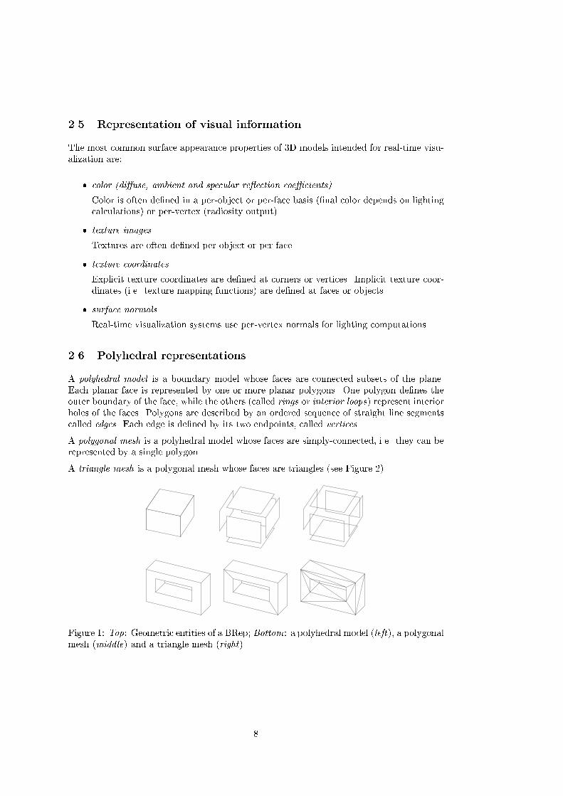
��� Polyhedral representations
A polyhedral model is a boundary model whose faces are connected subsets of the plane�Each planar face is represented by one or more planar polygons� One polygon de�nes theouter boundary of the face� while the others �called rings or interior loops� represent interiorholes of the faces� Polygons are described by an ordered sequence of straight line segmentscalled edges� Each edge is de�ned by its two endpoints� called vertices�
A polygonal mesh is a polyhedral model whose faces are simply�connected� i�e� they can berepresented by a single polygon�
A triangle mesh is a polygonal mesh whose faces are triangles �see Figure ��
Figure �� Top� Geometric entities of a BRep� Bottom� a polyhedral model �left�� a polygonalmesh �middle� and a triangle mesh �right�

Figure � Rendering of a mug represented with a triangle mesh �left�� voxel decomposition�midlle� and digital picture �right�
����� Voxel�based representations
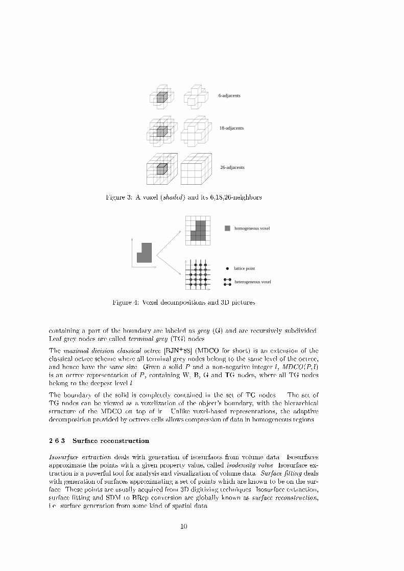
A voxel decomposition is a SDM whose cells are equal�sized cubes� called voxels� arranged ina regular array� Voxel decompositions are suitable for representing solid objects and volumedata� Solid objects are represented by labeling interior voxels as black �or �� and voxelsoutside the solid as white �or �� �see Figure �� For volume data representation� voxels arelabeled according to the the value of the property being modeled inside the voxel� In voxeldecompositions� the interior of voxels is considered to be homogeneous�
A �D picture is a set of points arranged in a regular grid de�ning equal�sized cubic cells�Points of a �D picture �called lattice points� are labeled according to the property beingstudied� The cubic cell de�ned by eight neighbor points is also called voxel� Unlike voxeldecompositions� �D pictures deal with voxels with non�homogeneous interior� since the prop�erty is only known at the lattice points� which coincide with voxel�s vertices �see Figure ��The space of interest can be conveniently scaled so that lattice points have integer coordi�nates� A �D digital picture is a set B � Z�� The elements of Z� are called points of thepicture� The points in B are called the black points of the picture� the points in Z��B arecalled the white points of the picture�
Two points in �D�space are said to be ��adjacent if they are distinct and each coordinateof one di�ers from the corresponding coordinate of the other by at most �� two points � �adjacent if they are ��adjacent and di�er in at most two of their coordinates� two points��adjacent if they are ��adjacent and di�er in at most one coordinate� In terms of voxels���adjacent voxels share a face� edge or vertex� ��adjacent voxels share a face or edge� and��adjacent voxels share only face� An n�neighbor of a point �resp� voxel� p is a point �resp�voxel� that is n�adjacent to p �see Figure ��� A set S of points is n�connected if S cannotbe partitioned into two sets that are not n�adjacent to each other�
����� Octree�based representations
The octree representation uses a recursive subdivision of a cubic universe into eight octantsthat are arranged into an �ary tree� In the classical octree representation �Sam��a� �COfor short�� each node consists of a code �often called color� and eight pointers towards eightsons� Nodes corresponding to cubic regions completely inside the object are labeled asblack �B�� Nodes corresponding to cubic regions completely outside the object are labeledas white �W�� White and black nodes are leaves� i�e� they are no further subdivided� Nodes
�
6-adjacents
18-adjacents
26-adjacents
Figure �� A voxel �shaded� and its ������neighbors
homogeneous voxel
lattice point
heterogeneous voxel
Figure �� Voxel decompositions and �D pictures
containing a part of the boundary are labeled as grey �G� and are recursively subdivided�Leaf grey nodes are called terminal grey �TG� nodes�
The maximal division classical octree �BJN�� �MDCO for short� is an extension of theclassical octree scheme where all terminal grey nodes belong to the same level of the octree�and hence have the same size� Given a solid P and a non�negative integer l� MDCO�P� l�is an octree representation of P � containing W� B� G and TG nodes� where all TG nodesbelong to the deepest level l�
The boundary of the solid is completely contained in the set of TG nodes� The set ofTG nodes can be viewed as a voxelization of the object�s boundary� with the hierarchicalstructure of the MDCO on top of it� Unlike voxel�based representations� the adaptivedecomposition provided by octrees cells allows compression of data in homogeneous regions�
����� Surface reconstruction
Isosurface extraction deals with generation of isosurfaces from volume data� Isosurfacesapproximate the points with a given property value� called isodensity value� Isosurface ex�traction is a powerful tool for analysis and visualization of volume data� Surface �tting dealswith generation of surfaces approximating a set of points which are known to be on the sur�face� These points are usually acquired from �D digitizing techniques� Isosurface extraction�surface �tting and SDM to BRep conversion are globally known as surface reconstruction�i�e� surface generation from some kind of spatial data�
��

� Scope of geometry simpli�cation
��� Denition of geometry simplication
Geometry Simpli�cation studies the simpli�cation of geometric models� i�e� the generationof geometric models that resemble the input model but involve less symbols� In order to becalled simpli�cation� the representation scheme must be preserved�
��� Components of a simplication process
The geometric model to be simpli�ed is called input model� and the underlying physicalobject represented by this model is called original object� The result of the simpli�cationprocess is referred as output or simpli�ed model� The input and the output models areslightly di�erent representations of the original object di�ering in complexity and accuracy�
The approximation error is a quanti�cation of the di�erence between the input model andthe simpli�ed model� The metric used for such a quanti�cation is called error metric� Whenthe error metric is expensive to compute� cheap error estimations are used instead�
Since geometric �delity and symbol reduction are opposite goals� the amount of reduction ofthe simpli�cation process is de�ned by user�de�ned parameters called reduction parameters�
��� Branches of geometry simplication
Depending on the dimension of the original object� several kinds of geometry simpli�cationmust be distinguished�
� curve simpli�cation
Curve simpli�cation deals with simpli�cation of curves embedded in a two�dimensionalor a three�dimensional space�
� surface simpli�cation
Surface simpli�cation deals with simpli�cation of surfaces embedded in a three�dimensionalspace�
� solid simpli�cation
Surface simpli�cation deals with simpli�cation of three�dimensional solids�
� volume simpli�cation
Volume simpli�cation deals with simpli�cation of volume models�
Two branches of surface simpli�cation are specially relevant�
� terrain simpli�cation
Terrain simpli�cation deals with simpli�cation of digital terrain models �DTM��
� isosurface simpli�cation
Isosurface simpli�cation deals with simpli�cation of boundary models generated byisosurface extraction techniques from volume data�
��

Furthermore� surface simpli�cation can be classi�ed according to the representation schemeused for the input and output models�
� arbitrary polyhedra simpli�cation
Polyhedra simpli�cation deals with simpli�cation of polyhedral models of solids andsurfaces�
� triangle mesh simpli�cation
Triangle mesh simpli�cation �mesh simpli�cation for short� deals with simpli�cationof triangle mesh representations of solids and surfaces�
��� Related disciplines
����� BRep construction from other schemes
As we pointed out in de�nition of geometry simpli�cation �Section ����� the representationscheme of the input model is preserved through the simpli�cation process� For instance�if the input model is a polygonal mesh� the output model must be a polygonal mesh too�When the representation schemes of the input and output models are di�erent� then we callthe process scheme conversion instead of simpli�cation� Scheme conversion is closely relatedto simpli�cation because sometimes is an alternative for generating level�of�detail represen�tations of an object� Evaluation is a kind of scheme conversion specially important for level�of�detail generation of curve� surface and solid models� Evaluation is the conversion from animplicit model into an explicit model� Examples of implicit models are parametric represen�tation of curves �Bezier� Splines����� surfaces �NURBS���� and solids �CSG�� Generation oflevel�of�detail boundary representations from an implicit model is generally straightforwardsince these models support the evaluation with di�erent levels of accuracy� For instance�the spacing between samples in parameter space de�nes the accuracy of the evaluation ofa parametric curve or surface� Similarly� level�of�detail representations of primitive solidssuch as spheres� cones and cylinders are straightforward to generate�
If both a parametric and an explicit representation are available as input� the evaluation usu�ally gives better results when trying to generate accurate approximations of simple objects�for generating coarse representations of complex objects� topology simpli�cation techniquesare required�
����� Geometry compression
A concept quite related to geometry simpli�cation is geometry compression� Geometrysimpli�cation preserves the representation scheme� so symbol reduction �vertices� edges�loops� faces� is achieved at the expense of accuracy� and hence simpli�cation is generallylossy�
Unlike geometry simpli�cation� geometry compression deals with loss�less coding of geomet�ric models� A common example of geometry compression of polygonal meshes consists ofstoring vertex coordinates in a separate array� and represent polygons as ordered sequencesof indices to the vertex array instead of the actual coordinates� A still more e�cient codingof a triangle mesh is the triangle strips coding �HB����
Some compressed schemes� such as triangle strips� have a decompression so e�cient that canbe decompressed in real�time �even by specialized hardware�� Other compression schemesare used only for e�cient storing and transmission of models� since they require an expensive
�

decompression or appropriate API�s are not available� Unlike geometry simpli�cation� thenumber of symbols of the input model is preserved through the compression�decompressioncycle�
����� Other kinds of simpli�cation in computer graphics
Yet it is out of the scope of this work� it is worth to mention other kinds of compression andsimpli�cation used in computer graphics�
� still image simpli�cation and compression
Run�length encoding is a simple and common loss�less compression scheme for stillimages� An example of lossy compression was de�ned by JPEG �Joi���� See �Cla� �for a review of compression of still images�
Unlike image compression� simpli�cation of images is achieved at the expense of imageresolution and involves minimizing �lters�
� video compression
Extensive work has been done in lossy and loss�less compression of digital video� See�Cla� � for a review of video compression schemes such as MPEG �MPFL���� �YL� ��
��� Level of detail and multiresolution models
Level of Detail is concerned to the possibility of using di�erent representations of a geometricobject having di�erent levels of accuracy and complexity�
Multiresolution models provide several level�of�detail representations of a geometric model�Such models have been proposed for e�cient handling of many geometric entities� curves�specially in GIS�� surfaces �mainly in computer graphics� virtual reality and GIS�� solids�computer graphics� CAD� virtual reality and object recognition� and volume data �scienti�cvisualization��
Multiresolution models must support the query for extracting a speci�c representation�Several architectures have been proposed in the literature�
� collection of LOD�s
A collection multiresolution model maintains a simple collection of independent LODrepresentations� The extraction of a speci�c representation is straightforward� Sinceeach representation is stored independently� the memory requirements is about thesum of the sizes of individual representations�
� hierarchical
A hierarchical multiresolution model maintains relations between consecutive LODrepresentations� so extraction of a speci�c representation requires several levels to beaccessed�
� incremental
An incremental multiresolution model maintains a compact structure from which dif�ferent LOD representations can be extracted� Usually this is achieved by storing acoarse representation and an ordered sequence of local updates� Extraction proceedsthrough the iterative application of updates starting from the coarse representation�until the representation has the required accuracy�
��

Regardless of the multiresolution model� the scene can adopt di�erent structures�
� per�scene LOD
The scene model involves a collection of LOD representations� each one containing adescription of all the objects in the scene� Coarse representations are used for inter�active tasks and accurate representations are used when accurate results are required�
� per�object LOD
The scene is represented by a tree or DAG� Terminal nodes correspond to individualobjects which are described by several LOD representations� The main advantage overthe per�scene approach is that each object can be processed at the optimum resolutiondepending on object�speci�c context�
� per�group LOD
Like in the per�object structure� the scene is represented by a tree or a DAG� but LODrepresentations are used not only for individual objects but also for groups� Existenceof LOD representation at intermediate levels provides a convenient way of representingcoarse representations of complex objects� For example� the coarser representation ofa house can be a textured box�
Generation of multiresolution models usually requires using a simpli�cation algorithm forthe generation of the LOD representations with varying reduction parameters�
��� LOD�based algorithms
LOD�based algoriths use multiresolution models to process geometric entities at the optimumresolution depending on application�speci�c contexts� For example� in real�time visualiza�tion� small� distant objects are displayed using coarse representations while close objects aredisplayed at full accuracy� In interactive collision detection� simpli�ed representations areused as a balanced solution between bounding boxes and the accurate representation�
The components of a LOD�based algorithm are a multiresolution model� and a selectionheuristic� The selection heuristic provides a mechanism to select the LOD representation tobe extracted from the multiresolution model according to speci�c application and contextrequirements�
An algorithmic paradigm related to LOD�based processing is that of context�varying geomet�ric processing� Such algorithms provide several ways to process geometric data dependingon accuracy and speed requirements� For instance� advanced display e�ects such as fog�anti�aliasing� texturing� and Gouraud shading are used or not depending on frame load� Amore sophisticated example found in high�end graphic systems is dynamic resolution� Dy�namic resolution is a dynamic adjustment of the virtual frame�bu�er resolution �used insuper�sampling�based anti�aliasing� in �ll�limited applications in order to get a �xed framerate� In these cases� the selection algorithm must select both the LOD representation andthe processing method�
��

� Applications
��� Operations over geometric models
As noted in de�nition of geometry simpli�cation �Section ����� simpli�ed representationsinvolve less symbols �vertices� edges� loops and faces� than their accurate counterparts� sosimpli�ed versions can be stored� processed and transmitted more e�ciently�
The following list contains the more relevant operations applied to geometric models� Manyof these operations can be done more e�ciently using simpli�ed representations�
� representation and storage
Geometric models need to be represented internally in main memory and stored innon�volatile media�
� transmission
Transmission of geometric models through computer networks is becoming more com�mon as the Internet and network�oriented standard formats such as VRML �ANM���are being used abroad�
Another kind of transmission� critical in high�end graphics hardware� is the communi�cation through the bus connecting the host with the graphics pipeline�
� real�time visualization
Visualization is used in conjunction with image�acceleration techniques� backfaceculling� viewing frustum culling� oclussion culling and LOD�based visualization� Oclus�sion culling requires visibility analysis preprocessing� and LOD�based visualizationrequires creation of multiresolution models�
� photo�realistic rendering
Photo�realistic rendering usually requires sophisticated techniques which currently can�not be applied in real�time� such as global illumination� ray�tracing� particle dynamicsand bump maps�
� collision detection
Collision detection �also known as interference detection� is usually used in real�timevisualization systems mock�up systems�
� spatial sound generation
Spatial sound generation is important in many virtual reality applications� Compu�tation of reverberation paths requires performing intersection tests between rays andrelevant objects of the scene� such as walls and �oors�
� boolean operations
Boolean operations �union� intersection� di�erence� etc�� are a powerful tool for creat�ing complex models from simple primitives�
� selection
Picking is used in CAD and other applications for selecting the objects to be a�ectedby future operations�
�

� geometric queries
Geometric queries range from volume and area computation� through integrity testsup to point inside solid tests and ray�solid intersection�
� scheme conversion
Geometric models often need to be converted to and from other representation schemes�
��� Pros and cons of using simplied representations
The potential gains of using simpli�ed representations are�
� store models more e�ciently� using less disk space to store them and less core memoryto represent them internally�
� reduce transmission times while sending models over computer networks�
� enable handling of complex scenes in limited hardware�
� accelerate real�time visualization by reducing the amount of data processed in moststages of the graphics pipeline� scene traversal� culling� data delivery� transformationand rasterization� Scene traversal cost depends on the number of symbols of sceneobjects� so reducing this number improves performance� The same argument holdsfor backface culling �depending on the number of faces� and real�time illumination�depending on the number of vertices�� Viewing frustum culling and oclussion cullingare already based on simple bounding volumes and constant visibility cells� respec�tively� However� preprocess required for oclussion culling �visibility analysis� can bedone more e�ciently with simpli�ed representations�
� accelerate photo�realistic rendering by reducing the amount of data being processedin scene traversal� vertex transformation� illumination computation� ray�tracing� etc�
� speed�up collision tests which depend on the number of symbols�
� faster geometric query processing� such as point inside solid test�
� accelerate spatial sound processing�
� apply boolean operations more e�ciently� When the simpli�cation process �ltersmodel degeneracies� boolean operations are also more robust�
� accelerate conversion to other representation schemes�
Simpli�cation gains will not be eclipsed by future hardware developments because manygeometric processing tasks have supra linear cost and because the size of geometric models isgrowing as long as more powerful hardware is becoming available� Advantages of simpli�edversions are more evident in processing tasks requiring supra linear running times sinceimprovements in hardware performance have little impact in the amount of data that canbe processed in real�time with such algorithms�
Unfortunately� there are several limitations of using simpli�ed representations�
� accuracy loss
Symbol reduction is achieved at the expense of accuracy loss� however� accuracy isfrequently higher than is required in many contexts �e�g� visualization of small� distantobjects��
��

� non�geometric data loss
When simplifying �D models� some non�geometric data may be lost during simpli�ca�tion� such as texture coordinates� per�vertex normals and surface properties�
��� Pros and cons of using compressed representations
The potential gains of using compressed representations are�
� store models more e�ciently� using less disk space to store them and less core memoryto represent them internally�
� dramatically reduce transmission times while sending models over computer networks�
� reduce bottlenecks while transmitting geometric data from the host to the graphicspipeline �e�g� triangle strips��
� accelerate per�vertex computations�
Like in simpli�cation� there are several limitations of using compressed representations�
� compression and decompression stages introduce an overhead� When decompressioncannot be done in real�time� compressed representations are used only for externalstorage and transmission over networks�
� some compression schemes are not fully loss�less� since they reduce vertex coordinatesaccuracy by vertex quanti�cation or prediction� Although this accuracy loss is smallcompared to simpli�cation techniques� integrity problems may appear when modifyingvertex coordinates �e�g� two�manifold surfaces become non�manifold��
� many current compression schemes do not fully support non�geometric data�
��� Pros and cons of using multiresolution models
Multiresolution models are the basis for LOD�based processing� With a few exceptions dis�cussed below� the gains of using simpli�ed representations can be obtained using multires�olution models� The main di�erence is that accuracy of the representation can be adjustedin real�time according to application�s requirements �e�g� need of interactive response� fromthe exact representation to a coarse one�
Per�object multiresolution models also allow this adjustment to be done in a per�objectbasis� according to application�s context �e�g� camera position�� Incremental multiresolutionmodels allow progressive transmission of geometric models over networks�
Like the previous approaches� using multiresolution representations has some limitations�
� multiresolution models need more storage and memory space than their single rep�resentation counterparts� specially multiresolution models maintaining collection ofindependent representations� which require about the sum of sizes of the representa�tions�
� only incremental multiresolution models can be transmitted e�ciently�
��
� representation selection and extraction introduce an overhead� Selection is criticalwhen its goal is to provide a �xed frame rate in real�time visualization� Extraction ismore expensive in incremental multiresolution models�
� LOD�based processing requires multiresolution models to be generated� There arethree ways of generating multiresolution models� interactively by hand �Cro�� �HG����i�e� modeling from scratch� as in old �ight simulators�� by automatic simpli�cationand by scheme conversion� The multiresolution model is generally computed previouslybecause existing methods are still too slow to be applied in real time�
� once created� multiresolution models are harder to update than single representations�for instance� color and textures changes must be spreaded over all LOD representations�
��� Specic contexts for geometry simplication
There are several contexts where simpli�cation is specially important�
� scenes inherently complex
Applications in areas such as automobile and shipbuilding design require huge modelscontaining hundreds or millions of objects �AAB���a��
� verbose representations due to the acquisition process
We say that a representation is redundant when the represented object can be describedwith the same accuracy and in the same representation scheme using less symbols�An example of redundant representations are polyhedral models containing adjacentcoplanar faces�
A representation is said to be verbose when the represented object can be describedwith an application�acceptable accuracy in the same representation scheme using lesssymbols� An example of verbose representations are those containing adjacent� quasi�coplanar faces�
Sometimes the complexity of the representation is due to the acquisition process�Surface �tting algorithms generate surface representations from spatial data acquiredthrough laser scanners� magnetic��eld digitizers� etc� Isosurface extraction algorithmsgenerate surface representations from volume data acquired through CT�scan� MRI�etc� Usually these reconstruction methods produce verbose representations becausethey are non�adaptive� i�e� they produce representations with the same symbol densityalong the surface� regardless of surface curvature� Most reconstruction methods areunable to create large faces even in almost planar regions because face size is limitedby grid spacing �Kal���
� limitations of the representation scheme
Polyhedral models have a limited expressive power� only polyhedral objects can beexactly represented� Objects involving curved faces are represented by tesselating thesurface in planar patches� Objects with a mathematical description as much simple asa sphere require a large number of planar faces for accurate representation�
� disparity between accuracy requirements
A geometric model is frequently used by many applications and users during the lifecycle of the product� Objects are modeled with a high level of accuracy since theseproducts are usually manufactured from CAD output� However� other tasks such aspublic presentations and walkthroughs do not require such accuracy� Another example
�
is the representation of a car required by an automobile design application comparedto the that required by a tra�c simulation application�
� limitation of resources
Sometimes a geometric model cannot be processed by some applications because re�source limitation� the model can be too large to �t in the memory of the workstationor communication lines might be too slow to provide remote access at reasonable rates�
� need for interactive response
Many computer graphics applications require interactive output� but even high�endworkstations are unable to interactively display the huge amounts of polygonal dataavailable in industrial and academic areas� Frame rate is critical in applications suchas virtual reality where head�mounted displays with low frame rates produce disorien�tation�
Simpli�cation and multiresolution models have become a powerful tool in many areas� includ�ing CAD� GIS� virtual reality and scienti�c visualization� in tasks such as real�time visualiza�tion� progressive transmission� visibility analysis� acoustic modeling� geometric computation�verbosity reduction of reconstructed surfaces and multiresolution interactive modeling�
A few examples of speci�c applications include shipbuilding design� automobile design� ve�hicle simulators and VR walkthroughs�
��� LOD�based real�time visualization
The most obvious application of multiresolution models is found in real�time visualizationdue to the range from which an object can be seen in an interactive �ythrough� Objects thatcover a small portion of the screen can be displayed using coarse representations withoutseriously a�ecting image quality� Accurate representations are reserved for close� importantobjects� The need of multiresolution objects was originally stated in �Cla��� and discussedin �Cro�� where a representation selection based on the number of pixels covered by thebounding box of the object is proposed�
LOD�based real�time visualization is one of the image acceleration techniques� Anothersoftware�based image acceleration technique is oclusion culling� based on visibility analysis�Visibility analysis calculates those portions of the scene potentially visible from a speci�cpoint of view and store them in an appropriate structure which is accessed in real timefor occlusion culling �FvDFH���� Most visibility processing approaches are based on spacesubdivision in constant visibility cells �FST��� �TH���� �Smi����
As any LOD�based processing� LOD�based real�time visualization requires a multiresolutionmodel and a selection algorithm�
����� Representation selection
Representation selection in real�time visualization may pursue three di�erent goals�
� constant frame rate
the goal is to provide a constant frame rate trying to keep image quality as much aspossible� the minimum frame rate is de�ned by the user�
��

� constant image quality
the goal is to display the scene as fast as possible while maintaining a �xed� user�de�nedimage quality�
� optimum ratio
the goal is to provide an optimum ratio between image quality and frame rate� auser�de�ned parameter weights these opposite goals�
Multiresolution models must contain information for the selection algorithm such as theapproximation error of each representation� In visualization�oriented multiresolution models�a list of ranges at which each LOD representation must be displayed can be provided insteadof approximation errors� Ranges are de�ned by the minimum and maximum distances tothe observer for a given representation� This approach is adopted in VRML �ANM��� andOpen Inventor LOD�nodes�
Selection algorithms can be classi�ed as follows �FS����
� static selection
Static selection is based on estimating image error from the approximation error ofeach representation and the camera settings of the current frame� Static selectiondoes not take into account system performance and graphics pipeline load� It is usefulfor providing constant image quality� but frame rate is not �xed neither reasonablybounded�
� dynamic selection
Dynamic selection �also known as system�adaptive� takes into account current sys�tem performance� so frame rate homogeneity is increased� Dynamic selection can bereactive or predictive� Reactive selection uses history data about rendering times ofprevious frames to increase or decrease the threshold used for selecting representationsas in the static approach� Performance of LOD�based rendering based on reactive se�lection is highly dependent on frame coherence� Predictive selection tries to estimatefuture image complexity �FS��� in order to provide a �xed frame rate�
Regardless of the selection algorithm� there are several heuristics to evaluate the impact ofusing a simpli�ed representation in the image quality�
� pixels covered
Pixels covered by the object on the screen is the most common and simple heuristicused for LOD selection� This area is estimated by projecting its bounding box overthe screen plane�
� application�speci�c importance
Some objects have special meaning for the application� For instance� backgroundobjects in a crane simulator are far less important than cables and containers�
� proximity to focus area
This heuristic is based on distribution of photosensitive cells in the human retina�Assuming that human interest is centered on the center of the displayed image� objectsin the periferia can be displayed using simpli�ed representations� This heuristic isspecially useful when image is displayed through immersive systems such as head�mounted displays and CAVE�s�
�

� speed of the object
Objects than move rapidly with respect to the observer are hardly perceived so greaterimage error is acceptable�
����� Model requirements
Multiresolution models to be used only for real�time visualization have speci�c properties�
� model integrity relaxation
real�time visualization applications are somewhat less concerned with model integritythan other operations� so in many visualization applications� model integrity is notenforced� interpenetrating faces� repeated vertices� non�manifold boundaries and othermodel degeneracies are not relevant unless they impact the resulting image�
� visual information
visualization in some applications require a high degree of realism� so material prop�erties are combined with geometric models to produce �D models� LOD�based visual�ization requires not only geometric approximation but also appearance preservation�
� use of textures instead of complex shapes
An impostor is any �D model that retains less visual information than the originalbut can be displayed more e�ciently �MS� �� Impostors range from simpli�ed repre�sentations through textured boxes up to billboards� Billboards are textured polygonswhich are dynamically oriented so they always face the observer �RH���� Billboardsare useful for representing complex shapes with axial symmetry�
Due to these speci�c properties� many simpli�cation methods create visualization orientedmodels� such �RB��� which creates representations containing dangling points and lines�
����� The abrupt change problem
Image artifacts a�ect LOD�based visualization based on collection of LOD representations�Since each representation is stored separately� the number of levels of detail must necessarilybe small� and hence changes between two consecutive levels are abrupt� causing undesirablee�ects during transition from a level to another� Human visual system is specially sensibleto such popping e�ects�
There are many solutions to this problem� One approach consists of using simpli�ed repre�sentations only when image impact is very low� so just a few pixels are involved� Unfortu�nately� this approach is incompatible with the goal of maintaining a �xed frame rate� Somehigh�end API�s provide a mechanism to reduce these artifacts� In IRIS Performer �Eck����an image�space smooth transition is achieved by a weighted blending of both representationsin a small interval around the switch point�
Some surface simpli�cation methods allow a smooth transition between two consecutiveLOD representations �RB���� �Tur��� �HHK�� �� �Eea� �� �DLW���� using parameterizedrepresentations or incremental multiresolution models� but extraction overhead� which mustbe done in visualization time� may exceed the speed�up of the LOD�based visualization�
The previous techniques are not mutually exclusive� and both object�space and image�spacesmoothing techniques can be used together to reduce perception of image artifacts�
�

����� Appearance preservation
The �nal color of image pixels depends on many factors� some of them are �D model�independent� such as the lighting model� properties of light sources� and atmospheric e�ects�and other are included in the �D model� Visualization�oriented simpli�cation is concernedwith preservation of model�dependent visual properties�
� normal preservation
The overall orientation of faces should be preserved� since on�screen color in mostlighting models depends on surface normals� Radiosity models� which store �nal colorinformation in a per�vertex basis� are an exception to these rule� In this case� the sim�pli�ed representations must preserve the per�vertex or per�corner color information� Amethod for surface appearance simpli�cation which do not require the preservation ofoverall orientation of faces is presented in �COM��� The method is based on a param�eterization of the triangulated surface and the storage of surface appearance attributesin normal and color maps� Although it achieves very realistic approximations of com�plex shapes and provides a bound in the resulting image error� normal maps are stillavailable only in prototyped hardware �OL��� and texture maps increase rasterizationcost and can decrease overall performance if the graphics subsystem is �ll�limited�
� material properties preservation
Other surface appearance attributes� such as color and texture� must be preserved�When these parameters come on a per�face basis� faces with di�erent values for suchattributes can be merged together only if the impact on the resulting image is accept�able� Unfortunately� surface simpli�cation methods e�ectively handling such appear�ance attributes are still very rare �see �CPD����� �Hop�����
�� Simplication requirements for model transmission
Simpli�cation� compression and multiresolution models have di�erent applications in trans�mission of geometric models over computer networks� specially the Internet�
A simpli�ed representation can be transmitted faster as it involves less symbols than theaccurate representation� assuming that the simpli�ed representation replaces the accurateone�
Compression techniques allow quick� loss�less transmission as they code geometry and inci�dence information using less bits than uncompressed representations�
Multiresolution models require more time to be completely transmitted� but they allowprogressive transmission� a very coarse representation of a huge model can be downloadedin a few seconds� This very simple representation is re�ned as transmission proceeds untilit becomes the accurate representation �NAM����
Incremental multiresolution models are specially suitable for progressive transmission �Hop���since total transmission time is not too much greater than the transmission time requiredby the accurate representation� Simpli�cation algorithms based on multiresolution analysis�i�e� wavelets� �DLW���� �Eea� �� �CPD���� and progressive meshes �Hop��� are speciallysuitable for progressive transmission�
Multiresolution models storing a collection of independent LOD representations are alsouseful as they may contain a coarse representation used as a thumbnail of the model� fromwhich the user decides whether download or not the accurate representation�

��� Simplication requirements for geometric queries
Simpli�ed and multiresolution models have di�erent applications in geometric operationssuch as collision detection� visibility analysis� etc�
A simpli�ed representation can be processed faster as it involves less symbols than theaccurate representation�
There are two ways of using simpli�ed representations in geometric queries� In the lossyapproach� all queries are processed using simpli�ed representations� so reported results arealways approximate� In the loss�less approach� average running times of query operationscan be decremented by providing a quick answer report in simple cases� The precedents ofthis technique are bounding volumes such as bounding boxes and bounding spheres� whichin fact are super�simpli�ed representations� An example of loss�less query acceleration viasimpli�ed representation is found in collision detection� A preliminary test uses a simplebounding representation to quickly discard trivial cases of non�intersection�
In �Vel�� a hierarchical multiresolution model for geometric query acceleration is discussed�Collection of LODs based multiresolution models are being used for collision detection�AAB���a��
��� Summary of application�dependent requirements
The following table shows the requirements of simpli�ed� compressed and multiresolutionmodels according to the target application�
Use Model requirementsstorage compressed representationshost�graphics transmission real�time decompressiontransmission over networks incremental recovering
Figure � Requirements for compression
Use Model requirementsreal�time visualization appearance preservationvisibility analysis bounded errorcollision detection bounded errorgeometric queries bounded error� integrity enforcementreverberation sound topology simpli�cation
Figure �� Requirements for simpli�ed models
Use Model requirementsreal�time visualization appearance preservation� smooth transitionvisibility analysis bounded error� bounding volumescollision detection bounded error� bounding volumesprogressive transmission incremental multiresolution
Figure �� Requirements for multiresolution models
�

� Principles of geometry simpli�cation
��� Error control and measure
As noted in de�nition of geometry simpli�cation �Section ����� symbol reduction is achievedby simpli�cation algorithms at the expense of accuracy�
The approximation error is a quanti�cation of the di�erence between the input model and thesimpli�ed model� The metric used for such a quanti�cation is called error metric� When theerror metric is expensive to compute� cheap error estimations are used instead� Regardlessof the error metric adopted� approximation error is measured in object coordinates andhence it is application�independent�
Processing geometric objects using simpli�ed representations instead of accurate represen�tations produces an error in the result� called result error� which is consequence of theapproximation error� Result error can be viewed as the approximation error measured in re�sult space� Result error nature and quanti�cation is operation�dependent� In visualization�image error measures the color pixel di�erence of the image obtained using the simpli��ed representation compared to that obtained with the accurate representation� Geometricqueries with boolean output� such as collision detection� may report incorrect answers forsome inputs when using simpli�ed representations� In this case� result error depends onthe size of the set of inputs for which the test reports incorrect answers� called range er�ror� Similarly� reverberation sound operations measure the sound wave error� and geometriccomputations such as volume and area computation measure the error of the scalar valuereturned by the query� called scalar error�
The error perceived by the user is the result error and not the approximation error� so boththe reduction parameter and representation selection in LOD�based processing should bebased on result error and not on approximation error� However� there are three handicaps inusing result error for such purpose� First� result error measurement is operation�dependent�second� actual result error values are context�dependent� e�g� image error depends on lightingmodel� point of view� etc� Finally� in most applications result error is hard to evaluate� Dueto this problems� result error is roughly estimated using the approximation error�
����� Metrics for approximation error
Metrics used for the approximation error are critical because the approximation error is usedboth during simpli�cation process and during LOD selection to estimate the result error�
The most relevant scheme for the evaluation of the approximation error between two surfacerepresentations S and S� has two components� a distance function and a norm� The distancefunction is de�ned on S� on S� or on both surfaces� The approximation error is evaluatedwith any function norm such as L� or L��
The most useful metric for comparing two surfaces is the Hausdor� distance �Gr�u���� TheHausdor� distance dH of a surface S with respect to S� is de�ned as
dH�S� S�� � maxS �minS ��dist�p� p����� ���
where dist is the Euclidean distance between two points� The symmetric Hausdor� distancedSH is de�ned as
dSH�S� S�� � max �dH�S� S��� dH�S�� S��� ��
�

����� Error components
�D models contain geometric and surface properties for visualization realism� Sometimessurface properties are de�ned globally� i�e� in a per�object basis� and sometimes are de�nedlocally� in a per�face� per�vertex o per�corner basis�
Ideally� a metric for the approximation error must be good enough to ensure that if theapproximation error is bounded in the sense de�ned by the metric then the result erroris also reasonably bounded� Approximation error metrics for bounding range and scalarerrors can be based only on geometric properties� Unfortunately� geometric approximationerror is not enough to reasonably bound image error� In addition to the geometric error��D model simpli�cation for visualization applications must deal with the error producedby modifying appearance attributes in the simpli�ed representations� so the approximationerror has several components� the geometric error� and an error for each visual propertyde�ned�
��� Measuring model complexity
Polyhedral representations have two kinds of complexity� geometric complexity� which de�pends on the number of faces� loops� edges and vertices of the model� and topology com�plexity� which depends on topology invariants of the represented surface such as the genusand the number of shells� Geometric and topology complexity are closely related by theEuler�Poincare formula
v � e� f � �s� g� � h� ���
where v� e� f � s� g and h are resp� the number of vertices� edges� faces� shells� genus andrings �interior loops in faces��
An application�independent approach for measuring geometric complexity is based on sumof the geometric entities of the polyhedral model� f � e� v� where f � e and v are resp� thenumber of faces� edges and vertices�
The application�dependent version of the previous index is de�ned as�
fcf � ece � vcv� ���
where cf � ce and cv are resp� the application�dependent unit cost of processing a face� edgeor vertex� For evaluation of storage requirements� cf � ce and cv are resp� the number of bitsrequired for storing a face� edge or vertex� Note that in some applications only one of thesemagnitudes is relevant� For example� backface culling cost depends only on the number offaces� wire�frame visualization depends on the number of edges� and per�vertex lighting costdepends only on the number of vertices�
Since geometric magnitudes are related by Euler�s formula� some of them can be computedfrom the others� In the particular case of triangle meshes representing closed manifolds� anyof f � e� v is enough for computing the others� since �f � e �PRS��� assuming one shelland genus zero�
When comparing geometric complexity of two polyhedral representations� several metricshave been proposed� The most simple approach is�
f � f �� � �
where f and f � are the number of faces of the input and output representations� resp� Thisis the most used metric for measuring complexity of triangle meshes �RB���� although it isnot suitable for arbitrary polyhedral models since it ignores face complexity�

A face ratio does not depend on the absolute size of the model ��SZL����
f
f �� ���
We propose a new metric for measuring geometric complexity of arbitrary polyhedral models�This metric is required for comparing simpli�cation methods generating triangle meshes withmethods generating arbitrary polyhedral models�
f � e� v
f � � e� � v�� ���
��� Topology preservation vs� topology simplication
Geometric simpli�cation deals with simpli�cation of the geometric complexity of polyhedralmodels� Topology simpli�cation deals with simpli�cation of the topology complexity of poly�hedral models� Since in polyhedral models topology is implicitly represented by geometricsymbols� by topology simpli�cation we mean the appropriate modi�cation of the surfacetopology in order to further reduce geometric complexity� Note that topology simpli�cationoften involves genus and shell reduction� but in some cases involves genus or shell creation�
Topology preservation is required in some applications such as medicine visualization andmolecular modeling� where presence or absence of tunnels is critical for correct data inter�pretation� specially if the simpli�ed simpli�cation is intended to substitute the input repre�sentation� However� topology preservation limits the amount of symbol reduction �Hea���specially in topologically complex objects and assemblies� Topology simpli�cation is suitablewhenever surface topology has not essential meaning or when the simpli�ed representationis intended to be part of a multiresolution model�
��� Curve Simplication
Curve simpli�cation deals with simpli�cation of polygonal curves embedded in D or �Dspace� Curve simpli�cation is a well known problem� There exists many di�erent approachesand plenty of methods �see �HI��� �II�� �Vel��� �ET��� �Bal����
Polygonal curves are represented by an ordered sequence p�� � � �� pn of points called vertices�The vertices of the simpli�ed curve are usually a subset of the original vertices� so thesimpli�ed curve can be represented by pi� � � � �� pim � where � � i� � i� � � � � � im � n�
Metrics to mesure the approximation error between curves are quite simple� All metrics arebased on comparing each edge pj � pk of the simpli�ed curve with the edges pj � � � �� pk beingrepresented by this edge �see Figure ��
The most common error metrics for curve simpli�cation are de�ned as follows �II� �seeFigure ���
� e� �distance edge�vertices
e� � maxl�dist�segment�pj � pk�� pl�� where l ranges from j to k�
� e �distance straight line�vertices or parallel strip error
e � maxl�dist�line�pj � pk�� pl�� where l ranges from j to k�
�
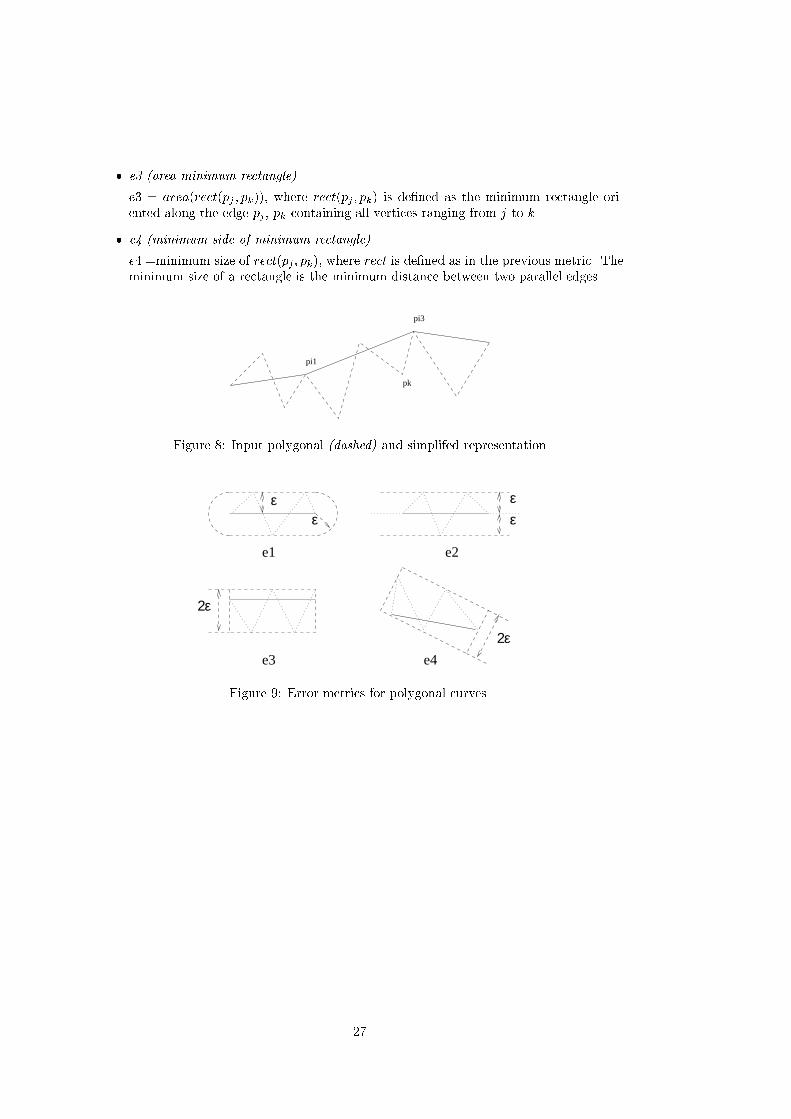
� e� �area minimum rectangle
e� � area�rect�pj � pk��� where rect�pj � pk� is de�ned as the minimum rectangle ori�ented along the edge pj � pk containing all vertices ranging from j to k�
� e� �minimum side of minimum rectangle
e� �minimum size of rect�pj � pk�� where rect is de�ned as in the previous metric� Theminimum size of a rectangle is the minimum distance between two parallel edges�
pi3
pi1
pk
Figure � Input polygonal �dashed and simplifed representation
εε
εε
2ε
2ε
e1 e2
e3 e4
Figure �� Error metrics for polygonal curves�
�

� Characterization of surface simpli�cation methods
In this section a new characterization of surface simpli�cation methods is proposed� Thesecriteria are grouped according whether they refer to input domain� approximation error�output domain� or algorithm internals�
��� Criteria about input domain
� representation scheme domain
This work focuses on simpli�cation of solids and surfaces represented by polygonalmodels� However� some surface simpli�cation methods accept as input other kinds ofrepresentation schemes in addition to boundary representations� such as constructivemodels or space decomposition models�
� geometric domain
Some simpli�cation algorithms require the input representation to have particular ge�ometric properties� such as convex surface or orthogonal faces� Other methods requiretwo�manifold� non self�intersecting surfaces� This criterion includes pure geometricproperties and the incidence properties de�ned by the topology of vertices� edges andfaces�
� topology domain
Some simpli�cation algorithms require the input representation to describe a surfacewith particular topology� such as genus zero or single shell surfaces� Note that in thiscriterion we are interested in the topology of surfaces� not in the topology of geometricelements �vertices� edges� faces��
� focus domain
Focus domain is the set of input representations for which the simpli�cation algorithmis oriented� such as reconstructed surfaces�
� scalability
Scalability measures how easy is to apply the simpli�cation algorithm to large amountsof objects� Need of human intervention and non�intuitive user�de�ned parametersdecrease scalability�
� appearance preservation
This criterion indicates how the simpli�cation algorithm handles visual informationsuch as color and textures� There are three approaches� no support at all �visual infois discarded�� partial support �visual info is not taken into account during the simpli��cation process� but it is included in the simpli�ed representation� and full support�the simpli�cation process takes as input both geometric and visual information� bothare simpli�ed and present in the simpli�ed representation�� Partial support usuallyinvolves no vertex creation� so texture coordinates� vertex normals� etc� can be directlyimported from the input representation�
��� Criteria about approximation error
� user�de�ned parameters
This criterion is concerned with user�de�ned parameters required for the simpli�cationalgorithm�

� reduction parameter speci�cation
This criterion refers to how the reduction parameter is de�ned� The reduction parame�ter is user�de�ned and indicates in some way the desired degree of simpli�cation� Thereare three ways of describing the reduction parameter� min�� min� and weighting� Inthe min� approach� the reduction parameter gives the size desired for the simpli�edrepresentation� by means of the number or percentage of vertices� edges or faces� andthe simpli�cation algorithm tries to generate a representation with required size withthe minimum approximation error� In the min� approach� the reduction parametergives the maximum approximation error acceptable� and the simpli�cation algorithmtries to generate a representation within this bound with the minimum number ofgeometric entities� In the weighting approach� the reduction parameter is a weight forthe opposite goals of accuracy and concision�
� error metric
The approximation error can be measured in many ways� such as the Hausdor� distancebetween two surfaces�
� bounded error
This criterion indicates whether the user can de�ne the maximum approximation error�using the min� approach� or not�
� error report
This criterion indicates whether the simpli�cation algorithm allows the approximationerror to be reported after simpli�cation�
��� Criteria about output representations
� representation scheme output
This criterion refers to the representation scheme of the output� a particular BRep�polyhedral model� polygon mesh or triangle mesh�� or multiresolution model �collec�tion of LODs� hierarchical or incremental�� Some methods generate compressed BRep�such as triangle strips to represent triangle meshes�
� geometric properties
Geometric properties of the simpli�ed representations� For instance� preservation ofrelevant features such as sharp edges�
� vertex creation
This criterion indicates whether the simpli�cation algorithm generates vertices at newpositions� or vertices of simpli�ed representations are subsets of input vertices�
� topology preservation
This criterion indicates whether the simpli�ed representation represents a surface topo�logically equivalent to the input surface� or the simpli�cation algorithm is able tochange surface topology� Surface topology is determined by topological invariantssuch as genus and number of shells�
� smooth transition
This criterion indicates whether the simpli�cation algorithm provides some mechanismfor smooth transition between consecutive LOD�s� in order to avoid the abrupt changeproblem�
�

� simpli�cation limit
This criterion indicates the simpli�ed representation generated by the simpli�cationalgorithm when maximum face reduction is demanded�
��
� Surface simpli�cation strategies
Surface simpli�cation methods can proceed top�down or bottom�up� In top�down methodsthe key ingredient is a face reduction process� Top�down methods build a working repre�sentation initially set to the input representation� and reduce the number of faces by someface reduction strategy� so accurate representations are produced �rst than coarse ones�because coarse representations require more face reduction steps than accurate ones� Inbottom�up methods the key ingredient is a re�nement process� Bottom�up methods startfrom a very rough approximation and increase the number of faces by some re�nementstrategy� so coarse representations are produced �rst than accurate ones� because accuraterepresentations require more re�nement steps than coarse ones�
�� Face reduction strategies
A classi�cation of face reduction strategies depends on the internal representation adopted�There are basically two approaches� those using directly a polyhedral BRep and those usinga SDM�
Face reducion strategies based on polyhedral BReps are�
� vertex clustering
The vertex clustering strategy consists of grouping close vertices in groups called clus�ters� All vertices inside a cluster are replaced by a single vertex� called cluster represen�tant� These replacements cause many edges and faces to collapse� Repeated collapsedentities are removed� This strategy is adopted in �RB���� �Tan��� and �Red����
� incremental face reduction
Incremental face reduction �also known as decimation� works by the iterative elim�ination of geometric entities through a local reduction operator chosen upon localgeometric optimality criteria� Local reduction operators are the basis of the majorityof simpli�cation methods �SZL��� �Gue���� �RR���� �AS���� �GH���� �Ham���� �DZ�����KCHN���� �HH���� �KT��� � �KT���� �CCMS���� �BBCS���� �HDD����� �Hop���� �Hop���and �PH����
� re�tiling
The re�tiling strategy consists of introducing new vertices on the original representationwhich are moved over maximal curvature locations� then a new triangulation is builtincluding the original and the new vertices� �nally� original vertices are removed by alocal reduction operator� This strategy was originally proposed in �Tur���
� wavelet decomposition
Simpli�cation based on wavelet decomposition proceeds through two steps� re�meshing�where a simple mesh approximating the input surface is generated� and wavelet param�eterization� Wavelet decomposition is used in several simpli�cation methods �Eea� ���DLW���� �CPD���� and �GSG����
Face reduction strategies based on SDM �rst convert the input representation into a SDM�a polyhedral surface is then constructed from the SDM� Accuracy level is determined bySDM cell size�
��

�� Local operators over triangle meshes
In this section we compare the mesh operators� which are the key ingredient of the majorityof surface simpli�cation methods� specially those following an incremental face reductionstrategy� Local operators either reduce mesh complexity �reduction operators� or improvethe �tting of the simpli�ed mesh ��tting operators��
The following reduction operators have been proposed in the geometry simpli�cation liter�ature �see Figure ����
� vertex�removal
The vertex�removal operator takes as parameter the vertex to be removed� The vertexand its t incident triangles are removed� The resulting hole is triangulated using t� triangles� The only computed parameter is the new incidence graph of the hole�striangulation� since no new vertices are inserted� The operator reduces the overallnumber of faces by two� the number of edges by three and the number of verticesby one� Except in degenerate cases which can be easily identi�ed by inspection ofthe incidence graph� the vertex�removal operator preserves the topology of the mesh�To avoid self�intersections� additional geometric tests are required� The selection ofthe vertex to be removed is commonly based on a curvature estimation at the vertex�Vertices with low curvature values are removed �rst� The vertex removal operator isused in �SZL��� �ea���� �SL��� and in most terrain simpli�cation methods�
� edge�collapse
The edge�collapse operator takes as parameter the edge to be collapsed� or its equiva�lent� a pair of vertices sharing an edge� The two vertices are collapsed in one vertex�As a result of this collapse� the triangles sharing the edge degenerate in a segment andare removed� The only computed parameter is the new vertex position� which usuallyis that of one of the two old vertices� or a weighted average� The operator reducesthe number of faces by two� the number of edges by three and the number of verticesby one� Except in degenerate cases which can be easily identi�ed by inspection of theincidence graph� the edge�collapse operator preserves the topology of the mesh� Toavoid self�intersections� additional geometric tests are required� The selection of theedge to be removed is commonly based on an estimation of the error in the Hausdor�distance sense� Usually� feasible edge�collapse operators are computed in a previousstep� and stored in priority queue ordered by error� The edge�collapse operator is usedin most of the state�of�the�art methods� �RR���� �Gue���� �AS���� �Hop���� �Hop����
� vertex�clustering
The vertex�clustering of v vertices is conceptually equivalent to v�� vertex�clusteringoperation involving just two vertices �pair contraction�� so we will review only thislatter form� The pair contraction operator takes as parameter the two vertices tobe collapsed� When these vertices are connected along an edge� this operation is anedge�collapse� but disconnected vertices are also allowed to be collapsed� If the lattercase� only the number of vertices is reduced� otherwise� the triangles sharing the edgedegenerate in a segment and are removed� The only computed parameter is the newvertex position� which usually is that of one of the two old vertices� or a weightedaverage� If the vertices are connected by an edge� the operator reduces the numberof faces by two� the number of edges by three and the number of vertices by one�otherwise only reduces the number of vertices� Unlike previous reduction operators� thepair contraction does not preserve the topology of the mesh� and creates non�manifoldmeshes� To avoid self�intersections� additional geometric tests are required� In the
�

simpler methods� the selection of the vertices to be collapsed is based on geometricproximity� Usually� several vertices are clustered at a time� The vertex�clusteringoperator is used in �RB���� �RR���� �Red���� �GH����
� face�removal
The face�removal takes as parameter the triangle T to be removed� This triangle and allits neighbors sharing one vertex with T are removed� The resulting hole is triangulatedwith the help of a new vertex� The computed parameters are the coordinates of thenew vertex� and the incidence graph of the triangulation� The operator reduces thenumber of faces by four� the number of edges by six and the number of vertices by two�Except in degenerate cases which can be identi�ed �Ham���� the face�removal operatorpreserves the topology of the mesh� Due to the high number of triangles involved�incremental methods using face�removal rapidly arrive to a mesh which cannot befurther simpli�ed while maintaining its validity� stopping at representations whereother simpler operators such as edge�collapse could be applied� The face removaloperator is used in �Ham����
In addition to reduction operators� which modify the count of the geometric entities of themesh� surface simpli�cation methods often rely on �tting operators�
� edge��ip
The edge��ip operator �also known as edge�swap� takes as parameter two adjacenttriangles �or their shared edge�� The non�planar quadrilateral resulting of mergingtogether both triangles is triangulated using the opposite diagonal� There are nocomputed parameters� The edge��ip operator preserves the topology of the meshbut not the incidence graph� To avoid self�intersections� additional geometric testsare required� The edge��ip is used for two purposes� a� to improve the �tting ofthe simpli�cation to the original surface� in non��at regions� and b� to create well�shaped triangles� in �at�regions� The edge��ip operator is used in �Hop���� �CCMS�����BBCS���� to minimize the error produced by another previous operator� such as edge�collapse�
� vertex�displacement
The vertex�displacement operator take as parameter the vertex to be moved� Theonly computed parameters are the new coordinates� usually given as an o�set vector�The vertex�displacement operator preserves the topology of the mesh and the incidencegraph� To avoid self�intersections� additional geometric tests are required� The vertex�displacement is used to locally improve the �tting of the simpli�cation to the originalsurface� Its relevance is due to the fact that the vertex displacement is closed in thedomain of valid triangle meshes �i�e� it preserves the validity�� this does not hold forarbitrary polyhedra� since vertex�displacement would produce non�planar faces�
In our opinion edge�collapse is the most suitable operator for face reduction� There aretwo reasons for that� its simplicity �only a�ecting two triangles at a time�� allowing furthersimpli�cation when other operators cannot be applied� and its generality� in the sense thatall topology�preserving reduction operators can be derived from a series of edge�collapsesand edge��ips�
� One vertex�removal can be replaced by an edge�collapse and several edge��ips�
� The multiple vertex�clustering of n vertices can be replaced by n� � vertex�clusteringof two vertices� which in turn is a generalization of edge�collapse to arbitrary pairs ofvertices�
��

c
b
a d
e
f
Figure ��� Reduction and �tting operators� a� vertex�removal� b� edge�collapse� c� vertex�clustering� d� face�removal� e� edge��ip and f� vertex�displacement�
� One face�removal can be replaced by two vertex removal� and hence by two edge�collapses and several edge��ips� Note that� in the face�removal we are considering� thetriangulation is performed introducing a new vertex� Otherwise� three edge�collapsesinstead of two would be necessary�
��

Review of simpli�cation methods
��� Classication of surface simplication algorithms
Here we propose a new classi�cation of surface simpli�cation methods� Recall that nonpolyhedral surface simpli�cation� and loss�less compression are out the scope of this work�
A �rst group of simpli�cation methods are terrain simpli�cation methods� Terrain modelshave special properties that are taken into account by terrain simpli�cation methods� simplesurface topology� they can be represented using elevation grids� error measurement is simple�etc�
The second group is formed by triangle mesh simpli�cation methods �mesh simpli�cation forshort�� Mesh simpli�cation methods are classi�ed according to the face reduction strategy�vertex clustering� incremental face reduction� re�tiling or wavelet decomposition�
The third main group includes all methods based on space decomposition models�
SS
�������������������������������������������������������
Terrain �SR���
Mesh simplif
�������������������������������������
Bottom�up� �Vel���
Clustering� �RB���� �Red��� �Tan��� �GH��
Incremental
���������������
vertex� �SZL���� �ea��� �SL��
edge� �Gue��� �RR��� �AS��� �HDD����� �Hop��� �Hop��� �PH��
face� �Ham����
faces� �DZ���� �KCHN���� �HH���� �KT�� � �KT���
edge� ip� �CCMS��� �BBCS��
Re�tiling� �Tur���
Wavelets� �DLW���� �Eea���� �CPD���� �GSG��
Based on SDM
�Voxels� �HHK����� �Hea��� �MSS���� �HB���
Octrees� �JAS���� �AAB��a�� �AAB��a�
��� Terrain simplication methods
Terrain simpli�cation deals with simpli�cation of digital terrain models �DTM for short��DTM models are broadly used in Geometric Information Systems �GIS for short�� The mostcommon representations for DTM are�
� points on a regular grid
The array of height values is imported together with the grid information �resolution�location of the sampled area� etc��
� scattered points
Scattered sampling poings can be imported as a list of coordinates together with heightvalues�
�
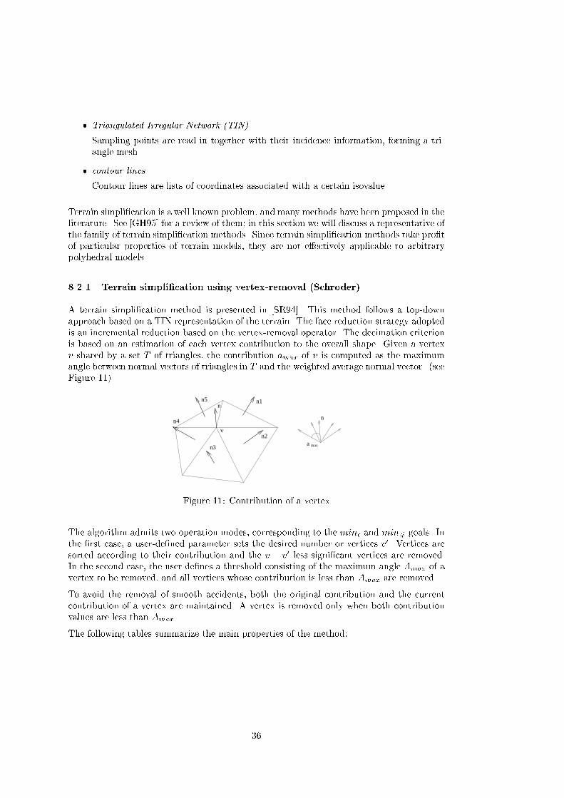
� Triangulated Irregular Network �TIN
Sampling points are read in together with their incidence information� forming a tri�angle mesh�
� contour lines
Contour lines are lists of coordinates associated with a certain isovalue�
Terrain simpli�cation is a well known problem� and many methods have been proposed in theliterature� See �GH� � for a review of them� in this section we will discuss a representative ofthe family of terrain simpli�cation methods� Since terrain simpli�cation methods take pro�tof particular properties of terrain models� they are not e�ectively applicable to arbitrarypolyhedral models�
����� Terrain simpli�cation using vertex�removal Schroder�
A terrain simpli�cation method is presented in �SR���� This method follows a top�downapproach based on a TIN representation of the terrain� The face reduction strategy adoptedis an incremental reduction based on the vertex�removal operator� The decimation criterionis based on an estimation of each vertex contribution to the overall shape� Given a vertexv shared by a set T of triangles� the contribution amax of v is computed as the maximumangle between normal vectors of triangles in T and the weighted average normal vector� �seeFigure ����
a max
n
vn2
n1n5
n4
n3
n
Figure ��� Contribution of a vertex
The algorithm admits two operation modes� corresponding to the min� and min� goals� Inthe �rst case� a user�de�ned parameter sets the desired number or vertices v�� Vertices aresorted according to their contribution and the v � v� less signi�cant vertices are removed�In the second case� the user de�nes a threshold consisting of the maximum angle Amax of avertex to be removed� and all vertices whose contribution is less than Amax are removed�
To avoid the removal of smooth accidents� both the original contribution and the currentcontribution of a vertex are maintained� A vertex is removed only when both contributionvalues are less than Amax�
The following tables summarize the main properties of the method�
��

Terrain simpli�cation using vertex�removal �Schroder�
Input
Representation scheme Triangle meshGeometric domain Terrain modelTopology domain UnrestrictedFocus domain Terrain modelsAppearance preservation Color can be included in decimation criteria
Approximation error
User�defined parameters Maximum angle Amax or target number of verticesReduction parameter Maximum angle Amax or target number of verticesError measurement LocalBounded error NoError report No
Output
Output Scheme Triangle meshGeometric properties Preserves even very small sharp edgesVertex creation NoTopology preservation NoSimplification limit Mesh with no trianglesUsability GoodTopology tests NoneSmooth transition No
The main contribution of this work with respect to the method proposed in �SZL�� is thenew criterion for vertex removal� which takes into account both the original contributionand the current contribution after some simpli�cation steps�
��� Mesh simplication methods
Mesh simpli�cation methods work with triangle meshes� To simplify arbitrary polyhedralmodels� a prior triangulation of the faces is required� In addition� these models producesimpli�ed representations involving only triangular faces�
As far as we know� all top�down methods internally using BRep representations always dealwith triangle meshes instead of arbitrary polyhedral models� There are two main reasons forthat� on one hand� in many cases the input representation is triangulated �as triangulatedis the output of most surface reconstruction methods� or needs to be triangulated �forvisualization purposes�� on the other hand� incidence relations of triangle meshes are farsimple than arbitrary polyhedra �And�b�� The �rst outcome of this fact is that reductionoperators become simpler� For instance� we can modify the coordinates of a vertex in atriangle mesh without producing a non�planar face� fact that does not hold on non�triangularmodels�
In this section we review the most relevant mesh simpli�cation methods �RB���� �SZL����ea���� �Ham���� �Tur��� �HDD����� �Eea� �� �DLW���� �CPD���� and �KT���� althoughother methods have been proposed �Hop���� �BBCS���� �KS���� �DZ���� �GGS� ��
��
����� Vertex�clustering Rossignac� Borrel�
A simple yet e�cient visualization�orientedmesh simpli�cation method is proposed in �RB����The face reduction strategy is based on all�at�once vertex�clustering� The method proceedsthrough �ve steps�
� weigth computation
For each vertex� a weight measuring its perceptual importance is computed� Theweight computation is based on the maximum angle and lengths of edges inciding atthe vertex�
� triangulation
If the input representation is not a triangle mesh� faces are triangulated�
� vertex grouping
Nearby vertices are grouped into clusters through gridding or coordinate truncation�The reduction parameter is de�ned by the grid subdivision�
� synthesis
Each vertex cluster is uni�ed in a single vertex� computed as the weithed average ofthe vertices inside the cluster �for a smoothing e�ect� or just the vertex with maximumweight �for detail removal��
� elimination
Vertex clustering causes many triangles to collapse into edges or points� In this step�repeated collapsed entities are removed� The result representation involves triangles�segments and points as primitives�
The main advantage of this method is that it is very simple and e�cient� and that thereduction parameter is very intuitive� Vertex positions can be parameterized so transitionbetween consecutive LOD levels is smooth�
Since this method is visualization�oriented� model integrity is very relaxed and the methodproduces simpli�ed representations with dangling triangles� segments and points�
�
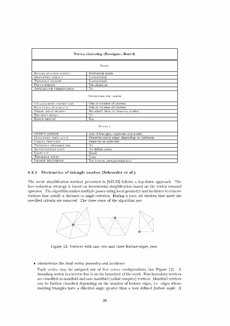
Vertex�clustering �Rossignac� Borrel�
Input
Representation scheme Polyhedral modelGeometric domain UnrestrictedTopology domain UnrestrictedFocus domain VisualizationAppearance preservation No
Approximation error
User�defined parameters Size or number of clustersReduction parameter Size or number of clustersError measurement Hausdor� distance between meshesBounded error NoError report Yes
Output
Output Scheme List of triangles� segments and pointsGeometric properties Preserves sharp edges depending on synthesisVertex creation Depends on synthesisTopology preservation NoSimplification limit An isolate pointUsability GoodTopology tests NoneSmooth transition Yes �vertex parameterization�
����� Decimation of triangle meshes Schroeder et al��
The mesh simpli�cation method presented in �SZL�� follows a top�down approach� Theface reduction strategy is based on incremental simpli�cation based on the vertex�removaloperator� The algorithm makes multiple passes using local geometry and incidence to removevertices that satisfy a distance or angle criterion� During a pass� all vertices that meet thespeci�ed criteria are removed� The three steps of the algorithm are�
Figure �� Vertices with one� two and three feature edges� resp�
� characterize the local vertex geometry and incidence
Each vertex may be assigned one of �ve vertex con�gurations �see Figure ��� Aboundary vertex is a vertex that is on the boundary of the mesh� Non�boundary verticesare classi�ed as manifold and non�manifold �called complex � vertices� Manifold verticescan be further classi�ed depending on the number of feature edges� i�e� edges whoseinciding triangles have a dihedral angle greater than a user�de�ned feature angle� A
��

vertex without feature edges is a simple vertex� A vertex used by two feature edges isan interior edge vertex� If one� three or more feature edges use the vertex� the vertexis classi�ed as corner vertex�
� evaluate the decimation criteria
Vertex evaluation depends on its classi�cation and on user�de�ned parameters� Auser�de�ned parameter determines whether feature edges must be preserved or not�Boundary vertices are evaluated according to an edge�vertex distance� Complex ver�tices are not deleted from the mesh� Simple vertices are evaluated measuring thedistance to an average plane� When feature edge preservation is selected� corner andinterior edge vertices are evaluated according to an edge�vertex distance� Otherwise�the distance to an average plane is used instead�
� apply the vertex�removal operator
The vertex and its associated triangles are removed� The resulting hole� which is star�shaped� is triangulated using a recursive splitting algorithm� Several tests are madein order to preserve the surface topology�
Unfortunately� the local error is accumulated through many iterations so the �nal approxi�mation error is not bounded�
Decimation of triangle meshes �Schroeder et al��
Input
Representation scheme Triangle meshGeometric domain UnrestrictedTopology domain UnrestrictedFocus domain UnrestrictedAppearance preservation Partial �no vertex creation�
Approximation error
User�defined parameters Reduction percentage or target number of vertices� edgepreservation �boolean�� feature angle� maximum distance
Reduction parameter Reduction percentage or target number of verticesError measurement LocalBounded error NoError report No
Output
Output Scheme Triangle meshGeometric properties Smoothes or preserves feature edges depending on parametersVertex creation NoTopology preservation YesSimplification limit Tetrahedron �for genus � meshes�Usability GoodTopology tests Many tests after triangulationSmooth transition No
����� Simpli�cation envelopes Cohen et al��
A general framework for a family of mesh simpli�cation methods is presented in �ea����
��
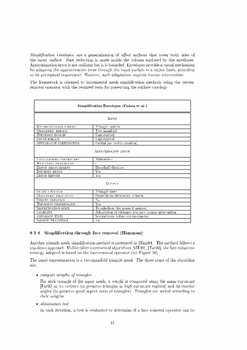
Simpli�cation envelopes� are a generalization of o�set surfaces that cover both sides ofthe input surface� Face reduction is made inside the volume enclosed by the envelopes�Approximation error is not uniform but it is bounded� Envelopes provide a visual mechanismfor adapting the approximation error through the input surface in a region basis� accordingto its perceptual importance� However� such adaptation requires human intervention�
The framework is oriented to incremental mesh simpli�cation methods using the vertex�removal operator with the required tests for preserving the surface topology�
Simpli�cation Envelopes �Cohen et al��
Input
Representation scheme Triangle meshesGeometric domain Two�manifoldTopology domain UnrestrictedFocus domain UnrestrictedAppearance preservation Partial �no vertex creation�
Approximation error
User�defined parameters Tolerance �Reduction parameter �
Error measurement Hausdor� distanceBounded error YesError report Yes
Output
Output Scheme Triangle meshGeometric properties Depends on decimation criteriaVertex creation NoTopology preservation YesSimplification limit Tetrahedron �for genus � meshes�Usability Adaptation of tolerance requires human interventionTopology tests Several tests before vertex�removalSmooth transition No
����� Simpli�cation through face removal Hamman�
Another triangle mesh simpli�cation method is presented in �Ham���� The method follows atop�down approach� Unlike other incremental algorithms �SZL��� �Tur��� the face reductionstrategy adopted is based on the face�removal operator �see Figure ����
The input representation is a two�manifold triangle mesh� The three steps of the algorithmare�
� compute weigths of triangles
For each triangle of the input mesh� a weigth is computed using the main curvature�Far��� at its vertices �to preserve triangles at high curvature regions� and its interiorangles �to preserve good aspect ratio of triangles�� Triangles are sorted according totheir weigths�
� elimination test
In each iteration� a test is evaluated to determine if a face removal operator can be
��

applied to the triangle with minimum weigth without changing mesh topology� Givena triangle T � its corona is the set of triangles sharing some vertex with T � excludingT itself �see Figure �� a�� A corona is called connected if it can be cyclically orderedso that each pair of consecutive triangles share an edge �see Figure �� b�� A coronais cyclic if it contains a subset of cardinality three where each triangle shares an edgewith two triangles �see Figure �� c y d�� Only triangles whose coronas are connectedand are cyclic can be removed� An additional halfspace criterion test guarantees thatresulting holes can be triangulated preserving the mesh topology�
� face removal
If all decimation criteria are meet� the triangle and its corona are removed� Theresulting hole is triangulated inserting a new vertex �see Figure �� e�� Then� someedge�split operators are applied over the new triangulation in order to improve theaspect ratio of new triangles �see Figure �� f�� Finally� a weigth is computed for eachnew triangle�
T
T TT T
a) b) c) d)
f)e)
Figure ��� a� A triangle and its corona� b� disconnected corona c� cyclic corona� d� acycliccorona� e� triangulation� f� diagonal interchange
The incremental simpli�cation stops when some user�de�ned reduction ratio is reached orwhen no more triangles can be deleted without changing mesh topology�
Since decimation criteria is based on curvature� and local errors are accumulated� the globalapproximation error is not bounded� Decimation can stop prematurely in still complexmeshes due to the large number of triangles and tests involved in decimation criteria�
�

Simpli�cation through face removal �Hamman�
Input
Representation scheme Triangle meshGeometric domain Two�manifoldTopology domain UnrestrictedFocus domain Tessellations of polynomial surfacesAppearance preservation No
Approximation error
User�defined parameters Reduction percentageReduction parameter Reduction percentageError measurement LocalBounded error NoError report No
Output
Output Scheme Triangle meshGeometric properties Two�manifold� good aspect ratioVertex creation YesTopology preservation YesSimplification limit Often is unable to reduce up to a tetrahedronUsability GoodTopology tests Connected� cyclic and halfspace tests in each iterationSmooth transition No
����� Superfaces simpli�cation Kalvin� Taylor�
A method for polyhedra simpli�cation using superfaces is presented in �KT����
The three steps of the algorithm are�
� superface creation
A superface is the non�planar contour of a set of connected faces of the input polyhe�dron� Superface creation is a greedy process of grouping adjacent faces �no geometricchanges are introduced yet�� Grouping criteria involve a planarity test �the distancebetween superface vertices and a set of planes approximated by an ellipsoid must beless than some user�de�ned Dmax�� an orientation test �the angle between the facebeing inserted in the superface and an average plane must be less than an user�de�ned�max�� a test for avoiding fold�over of the surface and an aspect ratio test computedas perimeter��area� Superface grouping stops when every input face belongs to asuperface�
� border straightening
The countour of each superface is divided into segments which are simpli�ed witha D polygonal simpli�cation method� The maximum deviation allowed for the Dsimpli�cation is computed from Dmax and �max�
� superface triangulation
Since superfaces are non�planar contours� they must be triangulated� Its vertices areprojected into an average plane and the superface is divided in star�shaped polygons�which are independently triangulated�
��

Although the input representation might contain arbitrary faces� the method only producestriangles� Since planarity� orientation and fold�over tests does not take into account face area�non�planar regions cannot be simpli�ed even when involved faces are small� Unfortunately�the simpli�ed mesh can self�intersect when the input does not� since two triangles fromdi�erent superfaces may intersect�
Superfaces simpli�cation �Kalvin� Taylor�
Input
Representation scheme Polyhedral modelGeometric domain UnrestrictedTopology domain UnrestrictedFocus domain LocalAppearance preservation Partial �no vertex creation�
Approximation error
User�defined parameters Dmax� �max� dmax
Reduction parameter Dmax� dmax� �max
Error measurement Distance between input vertices and simplied meshBounded error Yes� �Dmax
Error report Yes
Output
Output Scheme Triangle meshGeometric properties Might produce sel�ntersectionsVertex creation NoTopology preservation YesSimplification limit Tetrahedron �for genus � meshes�Usability RegularTopology tests No reportedSmooth transition No
����� Mesh optimization Hoppe et al��
A mesh simpli�cation using an optimization approach is presented in �HDD����� Thismethod follows a top�down approach based on a triangle mesh representation� The facereduction strategy adopted is an incremental reduction based on four local operators� edge�colapse� edge�split� edge��ip and vertex displacement� Unlike other incremental approaches�whose face reduction is driven by local criteria� in the method proposed in �HDD���� facereduction is directed by minimization of an energy function�
The energy function is de�ned over the domain of triangle meshes and models the oppositegoals of concise representation and �delity to the original mesh� Given the incidence graphK and the vertices V of the input mesh� the energy function is de�ned as the sum of threecomponents�
E�K�V � � Edist�K�V � �Erep�K� �Espring�K�V � ��
Edist measures �delity to the input mesh as the sum of squared distances of the pointsin X from the current mesh� where X is a set of points over the original mesh computedby uniform sampling� Edist�K�V � �
Pd��xi�M�� Erep measures the concision of the
��
representation and is proportional to the number of vertices� Erep�K� � crepv� where crepis a user�de�ned weight constant� Espring is a somewhat arti�cial component for keepingthe simpli�ed mesh from deviate in regions with low density of samples in X � measured asthe sum of edge lengths� The need of such component is a direct consequence of measuringthe approximation error as point to surface distance� because displacement of mesh verticeswithout no sampled points close to them have no e�ect on Edist� Unfortunately� Espring
has lateral e�ects as it penalties long edges� A user�de�ned constant� cspring weights thiscomponent�
The optimization problem is decomposed into two nested subproblems� although the methoddoes not guarantee the detection of the energy function global minimum�
� vertex optimization
Vertex optimization deals with optimizing the energy function by changing vertexcoordinates while preserving mesh incidence� Vertex optimization is based on thevertex displacement operator� First� for each point in X the closest point on thecurrent mesh is computed� Then� vertex positions are changed by square minimization�
� connectivity optimization
Connectivity optimization deals with optimizing the energy function by changing theincidence graph of the mesh through local operators while preserving vertex locations�Connectivity optimization is based on a reduction operator �edge�collapse�� a re�ne�ment operator �edge�split� and a �tting operator �edge��ip� �see Figure ���� Theedge�split is the inverse operation of an edge�collapse� The methods preserves surfacetopology since only legal �i�e� topology preserving� operators are applied�
The main advantage of this approach is the high quality of the simpli�ed representation�consequence of the energy function minimization and of changing vertex positions� Thealgorithm can also be used for surface �tting to an irregular point set�
Unfortunately� long processing times are required� Since approximation error is measuredusing a set of sampled points� the user is required to provide a weight cspring for the Espring
component� Since user�de�ned parameters are non�intuitive� unit�less weigth constants� theyare di�cult to set up �specially the reduction parameter crep� and results are hard to predict�The approximation error is unbounded�
�

Mesh optimization �Hoppe et al��
Input
Representation scheme Triangle meshGeometric domain Two�manifoldTopology domain UnrestrictedFocus domain UnrestrictedAppearance preservation Yes �in a subsequent work�
Approximation error
User�defined parameters Crep� Espring �unit�less� and number of samplesReduction parameter Crep
Error measurement distance between samples and simpli�ed meshBounded error No� in the Hausdor� distance senseError report Edist
Output
Output Scheme Triangle meshesGeometric properties Depends on sampling� Might preserve feature edgesVertex creation YesTopology preservation YesSimplification limit Tetrahedron �for genus � meshes�Usability Poor �non�intuitive parameters�Topology tests Tests in each iterationSmooth transition Yes �in a subsequent work�
���� Re�tiling polygonal surfaces Turk�
A mesh simpli�cation method based on an original re�tiling approach is presented in �Tur���The method follows a top�down approach� The face reduction strategy is based on a vertex�removal operator�
The three steps of the algorithm are�
� generate �nal vertices
The �rst step is to choose a set of points that will� at a later step� become the verticesof a new triangular tessellation of the surface� The number of points is user�de�nedand provides a mechanism for selecting the reduction degree� Once all points havebeen randomly placed on the surface� a relaxation procedure is applied to move eachpoint away from its nearby points through evaluation of repulsion forces�
� insert new vertices in the input mesh
The new vertices are inserted in the original polygons� and faces are triangulatedusing both the new and old vertices� This intermediate representation is called mutualtessellation� and it is topologically equivalent to the input surface�
� remove old vertices
The method �nally tries to remove old vertices using a vertex�removal operator� Oldvertices are not removed when the operation changes the surface topology� Unlike themethod proposed in �SZL��� topology preservation tests are made before the hole istriangulated� The result representation involves the new vertices and some old vertices�
��

The main advantage of this approach over other incremental methods based on the vertex�removal operator is that it is capable of creating vertices at new positions� Unfortunately�the approximation error is not bounded� and new vertices are placed without taking intoaccount surface curvature� so the method does not preserve sharped edges and vertices�
Re�tiling polygonal surfaces �Turk�
Input
Representation scheme Polyhedral modelGeometric domain Two manifoldTopology domain UnrestrictedFocus domain Smooth surfaceAppearance preservation No
Approximation error
User�defined parameters Target number of verticesReduction parameter Target number of vertices �the result might include more ver�
tices�Error measurement NoBounded error NoError report No
Output
Output Scheme Triangle meshGeometric properties Does not preserve feature edgesVertex creation YesTopology preservation YesSimplification limit Tetrahedron �for genus � meshes�Usability GoodTopology tests Tests for all input verticesSmooth transition Yes
����� Multiresolution analysis Eck at al��
A wavelet�based mesh simpli�cation method �You���� �RBC���� �Sak� �� �Dau�� is pre�sented in �Eea� �� The method is a generalization of a previous multiresolution analysismethod �DLW��� that overcomes the subdivision connectivity limitation� A triangle meshhas subdivision connectivity when it can be obtained from a simple mesh through the recur�sive ��to�� subdivision presented in Figure ���
Figure ��� ��to�� subdivision connectivity
The two steps of the algorithm are�
��

� re�meshing
The input mesh M is approximated by another mesh topologically equivalent butwith subdivision connectivity� First� a very simple mesh is computed using Voronoidiagrams �PM �� Then� a parameterization ofM over this simple domain is computed�Finally� ��to�� subdivisions are applied over the simple domain� inserting new verticesuntil the Hausdor� distance between Mj and M is bounded by a user�de�ned ���
� wavelet parameterization
The second step is based on multiresolution analysis �DLW���� The parameterizationis decomposed into a low�resolution part and a sequence of local correction terms calledwavelet coe�cients� Decomposition tolerance is user�de�ned as ���
Topology preservation is inherent to the method� The number of triangles of the originalmesh is doubled in the approximated mesh� Since multiresolution analysis cannot be applieddirectly over the input mesh� the �nal multiresolution representation is lossy even at thehigher level of the decomposition�
Multiresolution analysis �Eck at al��
Input
Representation scheme Triangle meshGeometric domain UnrestrictedTopology domain UnrestrictedFocus domain UnrestrictedAppearance preservation No
Approximation error
User�defined parameters Remeshing tolerance �� and decomposition tolerance ��Reduction parameter �� and ��Error measurement L� of Hausdor� distanceBounded error YesError report Yes
Output
Output Scheme Multiresolution of triangle meshesGeometric properties No reportedVertex creation YesTopology preservation YesSimplification limit Domain meshUsability RegularTopology tests NoSmooth transition Yes
��� Methods based on space decomposition models
����� SDM�based simpli�cation pattern
Polyhedral surface simpli�cation using intermediate SDM was originally proposed in �AAB� a�and �HHK�� �� SDM�based simpli�cation proceeds through three steps�
�
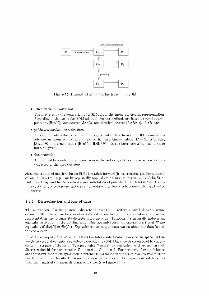
2
1
P
P
P
O
O
n
surface reconstruction
discretization
prunning
P
n
2
1O
Figure � � Example of simpli�cation based on a SDM
� BRep to SDM conversion
The �rst step is the generation of a SDM from the input polyhedral representation�According to the particular SDM adopted� current methods are based on voxel decom�positions �Hea���� face octrees �JAS� � and classical octrees �AAB� a�� �AAB���a��
� polyhedral surface reconstruction
This step involves the extraction of a polyhedral surface from the SDM� Some meth�ods use an isosurface extraction approach� using binary values �JAS� �� �AAB� a���AAB���a� or scalar values �Hea���� �HHK�� �� In the later case a isodensity valuemust be given�
� face reduction
An optional face reduction process reduces the verbosity of the surface representationsextracted in the previous step�
Since generation of multiresolution SDM is straightforward �it just requires glueing adjacentcells�� the last two steps can be repeatedly applied over coarse representations of the SDM�see Figure � �� and hence produce a multiresolution of polyhedral representations� A mul�tiresolution of octree representations can be obtained by iteratively pruning the last level ofthe octree�
����� Discretization and loss of data
The conversion of a BRep into a discrete representation �either a voxel decomposition�octree or �D picture� can be viewed as a discretization function dis that takes a polyhedralrepresentation and returns its discrete representation� Function dis naturally induces anequivalence relation in the polyhedra domain� two polyhedral representations P and P � areequivalent i� dis�P � � dis�P ��� Equivalence classes give information about the data lost inthe conversion�
In voxel decompositions� voxel represents the solid inside a cubic region of the space� Whitevoxels correspond to regions completely outside the solid� black voxels correspond to regionscontaining a part of the solid� Two polyhedra P and P � are equivalent with respect to suchdiscretization i� for each voxel c� P � c � � � P � � c � �� Furthermore� if two polyhedraare equivalent then their symmetric di�erence is contained in the set of black voxels of theirvoxelization� The Hausdor� distance between the interior of two equivalent solids is lessthan the length of the main diagonal of a voxel �see Figure �� b��
��

In �D digital pictures� which represent solid objects through a regular grid of points� twopolyhedra are equivalent i� for each lattice point p� p � P � p � P �� and hence� thesymmetric di�erence is not con�ned to any particular region and the Hausdor� distance isnot reasonably bounded �see Figure �� a��
B)
A)
Figure ��� Equivalent polyhedra with respect to a �D picture �a� and a voxel decomposition�b�
����� The surface reconstruction problem
Surface reconstruction from discrete data is a well known problem �Kal��� �PTN���� �GW�����KR��� In this section we review the main problems encountered in reconstructing polyhe�dral surfaces from octree and voxel�based representations� from the point of view of SDM�based simpli�cation�
Isosurface extraction algorithms can be classi�ed into two main groups �Kal��� D algo�rithms and �D algorithms� In D algorithms� volume data is processed as a series of D slices�surface reconstruction proceeds through two steps� �rst� a D contour is extracted from eachslice� and then a surface is generated by merging contours of adjacent slices �see Figure ����Contour�based surface reconstruction algorithms produce verbose representations becauseface size is limited by the distance between slices� Furthermore� contour matching oftenrequires human intervention due to the ambiguity problem�
Figure ��� Surface reconstruction algorithms based on contours
�

In �D algorithms� both the geometry and the incidence of the representation is generateddirectly from the SDM� There basically two families of such methods �Kal��� block�formor cuberille methods �FLP�� and beveled�form of marching cubes methods� Block�formmethods are based on voxel decompositions and generate surfaces gluing the square facesshared by voxels of di�erent color�
Beveled�form methods are often based on volume data sampled at regular points representedas �D pictures� Marching Cubes �LC�� is the most used representant of this family�
A block�form method cannot be applied directly from a �D picture� a mapping from a �Dpicture to a voxel decomposition is required before calling a cuberille�like reconstructionalgorithm� The most common mapping is to generate voxels centered at the lattice pointsand whose length is equal to the grid spacing �see Figure � a�� An alternative is consid�ering the voxels de�ned by adjacent lattice points� and whose color is determined by localneighborhood �see Figure � b��
C)
B)
A)
Figure �� Mappings between voxel decompositions and pictures
Similarly� beveled�form algorithms cannot be applied directly to a voxel decomposition� amapping to a �D picture is required �rst� A simple example generates lattice points at thecenter of each voxel �Figure � c��
����� Ambiguity in surface reconstruction from �D pictures
Since SDM only o�er approximate representations of polyhedra� each SDM can be recon�structed as several slightly di�erent polyhedra� called interpretations� Interpretations mightbe geometrically and also topologically di�erent� yielding to the ambiguity problem of surfacereconstruction from �D pictures� Ambiguity occurs at several levels�
�
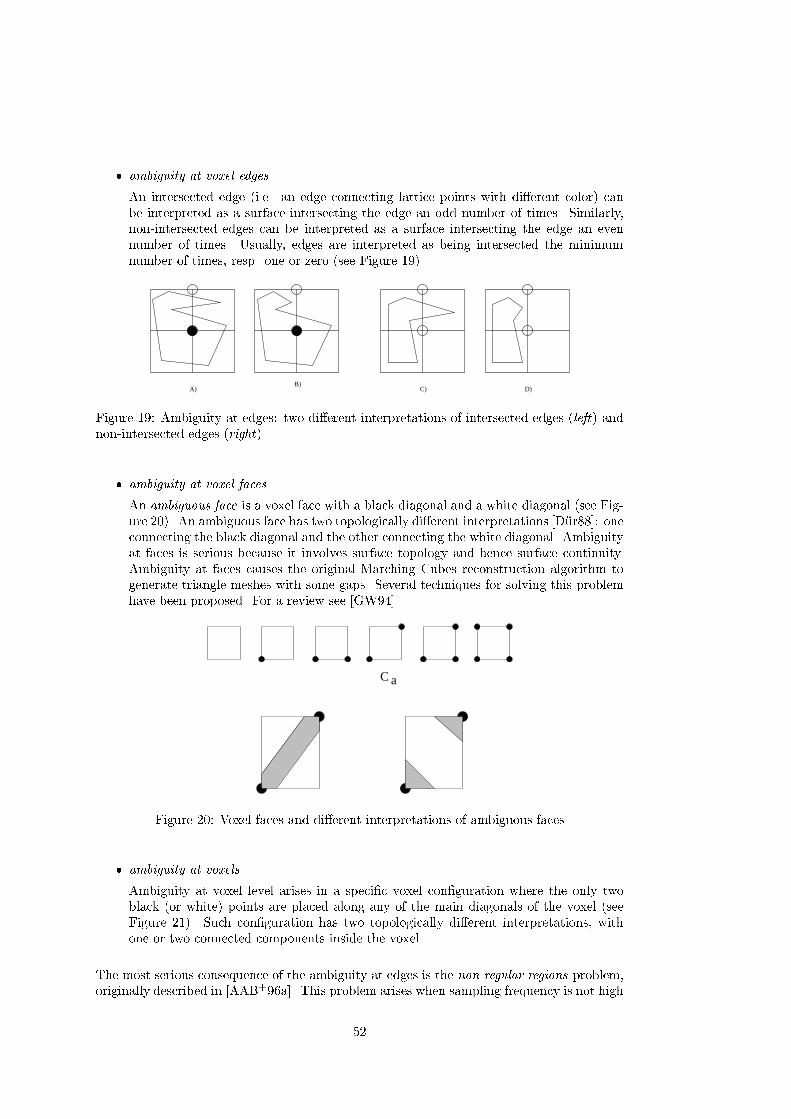
� ambiguity at voxel edges
An intersected edge �i�e� an edge connecting lattice points with di�erent color� canbe interpreted as a surface intersecting the edge an odd number of times� Similarly�non�intersected edges can be interpreted as a surface intersecting the edge an evennumber of times� Usually� edges are interpreted as being intersected the minimumnumber of times� resp� one or zero �see Figure ����
A)B)
C) D)
Figure ��� Ambiguity at edges� two di�erent interpretations of intersected edges �left� andnon�intersected edges �right�
� ambiguity at voxel faces
An ambiguous face is a voxel face with a black diagonal and a white diagonal �see Fig�ure ��� An ambiguous face has two topologically di�erent interpretations �D�ur�� oneconnecting the black diagonal and the other connecting the white diagonal� Ambiguityat faces is serious because it involves surface topology and hence surface continuity�Ambiguity at faces causes the original Marching Cubes reconstruction algorithm togenerate triangle meshes with some gaps� Several techniques for solving this problemhave been proposed� For a review see �GW����
aC
Figure �� Voxel faces and di�erent interpretations of ambiguous faces
� ambiguity at voxels
Ambiguity at voxel level arises in a speci�c voxel con�guration where the only twoblack �or white� points are placed along any of the main diagonals of the voxel �seeFigure ��� Such con�guration has two topologically di�erent interpretations� withone or two connected components inside the voxel�
The most serious consequence of the ambiguity at edges is the non�regular regions problem�originally described in �AAB���a�� This problem arises when sampling frequency is not high

Figure �� An ambiguous voxel with its di�erent interpretations
enough to capture thin surface features� Given a �D picture� a non�regular region is a �Dvolume that does not intersect any lattice point� and hence this �D volume is not representedin the picture� Non�regular regions can be arbitrarily large �see Figure �� although theymeet the following local thickness criterion� �p � S q � S j dmax�p� q� � l� where S is thenon�regular region� l is the grid spacing and dmax�p� q� � max�jpx�qxj� jpy�qyj� jpz�qzj��Non�regular regions existence depends not only on grid spacing but also on grid alignment�By de�nition� non�regular regions intersect voxel edges an even number of times� but due tothe edge ambiguity� these edges are interpreted as non�stabbed edges and hence non�regularregions are not reconstructed by isosurface extraction algorithms �see Figure ���
Voxel size~
Figure � Example of non�regular region
Figure �� Non�regular region corresponding to a solid �left� and to a cavity �right�
����� Volume bu�ers He�
A mesh simpli�cation method based on signal processing is presented in �HHK�� �� Theface reduction strategy is based on discretization into a �D picture followed by isosurfaceextraction� The main contribution of the method is the de�nition of the �D picture fromthe input representation�
The two steps of the algorithm are�
� sampling and �ltering
The input object is sampled and low�pass �ltered resulting in a �D picture where each
�

lattice point �i� j� k� has assigned a density f�i� j� k�� The density value depends on theamount of solid in the point�s neighborhood� and is computed as the following integralrestricted to the solid�
f�i� j� k� �
Z Z Zh�x� y� z�dxdydz ���
where h�x� y� z� is a low�pass �lter with an spheric support of radius R and linearlyweighted so that solid contribution is maximum in the center c and null at distanceR� h�p� � �R� dist�p� c���R� Actually� this �lter with �nite support is approximatedby a pre�computed discrete �lter�
� isosurface extraction
The result simpli�cation is generated by applying an isosurface extraction algorithmto the �D picture� The isosurface extraction method adopted is Marching Cubes� Theuser or the application must provide an isodensity value�
This method can be easily extended to support simpli�cation of non�polygonal representa�tions provided that they represent a closed �D volume� Since the low�pass �lter removeshigh�frequency details� the result representations are more smooth than the input represen�tation� Unfortunately� Marching Cubes produces verbose representations� involving manyfaces even in low�curvature regions� The approximation error is not bounded�
Voxel Based Object Simpli�cation
Input
Representation scheme UnrestrictedGeometric domain UnrestrictedTopology domain Surface enclosing a �D volumeFocus domain Smooth surfacesAppearance preservation No
Approximation error
User�defined parameters Grid spacing and �lter radiusReduction parameter Grid spacingError measurement NoBounded error NoError report No
Output
Output Scheme Triangle meshGeometric properties Two�manifold� no sharp edge preservationVertex creation YesTopology preservation NoSimplification limit OctahedronUsability GoodTopology tests N�ASmooth transition Anti�aliasing using several layers is reported
����� Simpli�cation using face octrees Joan�Arinyo et al��
An isosurface extraction method suitable for SDM�based simpli�cation is presented in �JAS� ��The method generates low�verbosity polygonal models from a voxel decomposition�
�

The four steps of the algorithm are�
� generate quadrilateral mesh
The �rst step computes a quadrilateral mesh covering the set of boundary voxels� Avoxel is said to be a boundary voxel when at least one of its ��neighbors is white�Quadrilaterals are de�ned by connecting the centers of four ��adjacent boundary vox�els�
� relax quadrilateral mesh
The quadrilateral mesh is relaxed using an energy function for moving mesh vertices�as in Geometrically Deformed Models �GDM for short� �MBL����� Relaxation isconstrained so that the vertices of the GDM lie inside the voxel they represent� Therelaxed GDM may include dangling quadrilaterals� which are removed from the mesh�
� generate face octree
A plane is computed for each vertex of the relaxed GDM� The plane is de�ned soit contains the vertex and its normal vector is computed as the normal average ofneighbor triangles� A face octree �Bru��� is generated by merging face nodes as muchas possible using as tolerance the length of the main diagonal of voxels�
� surface extraction
A surface is extracted from the face octree and the relaxed GDM� For each face noden of the face octree� the GDM vertices that lie inside n are projected into the planeassociated to n� Quadrilaterals whose four projected vertices lie inside node n aremerged together to generate a planar polygon� Quadrilaterals whose projected verticesbelong to di�erent face nodes are triangulated�
The main contribution of the reconstruction is that face�s size is not limited by voxel�s size�This method can be used for surface and solid simpli�cation using the basic scheme of SDM�based simpli�cation algorithms �see table below�� However� the reconstruction method isunable to reconstruct non�regular regions and some regular regions� for instance regions ofxxn voxels� Approximation error is bounded only in reconstructed regions�

Simpli�cation using face octrees �Joan�Arinyo et al��
Input
Representation scheme Any scheme� but must be translated to a voxel decompositionGeometric domain UnrestrictedTopology domain Surface must enclose a �D volumeFocus domain UnrestrictedAppearance preservation No
Approximation error
User�defined parameters Voxel size or number of divisionsReduction parameter Voxel size or number of divisionsError measurement Hausdor� distanceBounded error NoError report No
Output
Output Scheme Polyhedral modelGeometric properties Two�manifold� no self�intersectingVertex creation YesTopology preservation NoSimplification limit Empty model �no faces�Usability GoodTopology tests N�ASmooth transition No
���� SDM�simpli�cation using colored octrees Andujar et al��
An octree�based surface simpli�cation algorithm is presented in �AAB���a�� Given a poly�hedral solid P � a multiresolution of two�manifold� polyhedral solids s�� � � � � sn is generated sothat distH�P� si� � �i and face��si� � face��si���� where distH is the Hausdor� distancede�ned over the points on the solid�s boundary and f�ig is an increasing series of tolerances�
The face reduction strategy is based on using an intermediate SDM called maximal divisionclassical octree �MDCO for short� �BJN���
The method combines two di�erent kinds of voxel information� On one hand� terminal nodesof the MDCO track the surface on cubic regions� on the other hand� colors at terminal nodescorners capture solid presence at punctual places�
There are � � � di�erent con�gurations of the eight colors of terminal nodes �LC����Sri��� These con�gurations can be grouped by rotations ans symmetries into �� equivalenceclasses� �see Figure ���
The three steps of the algorithm are �see Figure ��
� BRep to MDCO conversion
The colored MDCO representation of the input polyhedron is generated by two si�multaneous processes of recursive space subdivision and clipping of polyhedron�s faces�CH��
TG nodes with all its vertices with the same color are called non�regular nodes� other�wise� they are called regular nodes� The following �gure shows proposed classi�cationof terminal nodes�
�

4 5 6
8 9 10 117 12 13
0 1 2 3
4
6
2 3
7
10
5
Figure �� The �� equivalence classes of voxels
Node
�������������������������������������������������������������������������������������
White
Back
TG
���������������������������������������������������������������������������
regular
���������������������������������������������������������������
unambiguous� ������������
r b
b b
b b
b b
r r
b b
b b
b b
r r
b b
r b
b b
r r
b b
r r
b b
r r
r b
r b
b b
r b
r b
r r
b b
ambiguous
�����������������������������
by face� ������������
r b
b r
b b
b b
b b
b r
r r
b b
b b
b r
b r
r b
b r
b r
r b
r b
r r
b b
r b
b r
b r
r b
r b
b r
by cube� �b b
b r
r b
b b
non�regular� �b b
b b
b b
b b
� generate multiresolution of MDCO
A multiresolution series of octrees with decreasing depth is generated by iterativelypruning the last level of the octree �see Figure � ��
� deambiguate TG nodes
Ambiguous TG nodes are subdivided so that resulting nodes are unambiguous� Then�TG nodes are classi�ed to de�ne a discrete topology where in nodes belong to discretefaces� on nodes belong to discrete edges and join nodes are discrete vertices �seeFigure �� The resulting structure is called TG�map�
� re�ne TG�map
The TG�map is re�ned until it de�nes a realizable topology� i�e�� until there exists afeasible polyhedron with the topology de�ned by the TG�map� Re�nement is con�
�

ducted by minimization of an energy function penalizing non�planar of discrete facesand non�linearly separable regions which cause non�planar faces to be splited and onand join nodes to be moved�
� geometry realization
A polyhedron is generated from the TG�map� A vertex is created for each join nodeand the incidence graph is de�ned by on and in nodes� Geometry is generated bymoving vertices minimizing the energy function�
P TGMAPi TGMAP-2Mi TGMAP-REFi PiMDCOi
MDCOi-1 TGMAPi-1 TGMAP-2Mi-1 TGMAP-REFi-1 Pi-1
MDCOo TGMAPo TGMAP-2Mo TGMAP-REFo Po
Figure � SDM�based simpli�cation using colored MDCO
A) B) C)
Figure �� �a� Original solid� �b� in� on and join nodes� �c� on and join nodes
Generated polyhedra are two�manifold and the approximation error is bounded in the Haus�dor� distance sense� Unlike previous approaches� this method produces faces with arbitrarysize and complexity �even with holes��

SDM�simpli�cation using colored octrees �Andujar et al��
Input
Representation scheme Polyhedral modelGeometric domain UnrestrictedTopology domain Surface must enclose a �D volumeFocus domain UnrestrictedAppearance preservation No
Approximation error
User�defined parameters Octree depthReduction parameter Octree depthError measurement Hausdor� distanceBounded error YesError report Yes
Output
Output Scheme Polyhedral modelGeometric properties Two�manifold� no sel�ntersectingVertex creation YesTopology preservation NoSimplification limit CubeUsability GoodTopology tests N�ASmooth transition No
����� Discretized Marching Cubes Montani et al��
A less verbose version of the original Marching Cubes� called DiscMC� is presented in�MSS���� The surface is enforced to intersect the edges at the midpoint� instead of comput�ing the intersection point by interpolation� Final vertices can be created only at �� di�erentlocations of a voxel �see Figure �a�� and faces may have only �� di�erent plane orientationswith respect to a voxel� x � c� y � c� z � c� x� y � c�x� z � c� y � z � c� x� y � z � c�
The look�up table is similar to that of MC� but some classes are reconstructed using rectan�gles instead of triangles� The ambiguity problem of MC is avoided by explicitly consideringthe complements of classes �� � y � �see Figure ���
The two steps of the surface reconstruction are�
� generate discrete faces
For each voxel intersected by the surface� DiscMC uses the look�up table to generatethe triangles and rectangles inside the voxel� Generated faces are inserted in any of�� hash tables depending on face orientation� For indexing the hash table� shape codeand cube index are used�
� coplanar faces merging
Each hash table is examined for adjacent faces� Adjacent coplanar faces are mergedwith the help of Freeman chains�
This surface extraction technique can be used in a SDM�based simpli�cation algorithm�Unfortunately� planar regions are reconstructed verbosily when their orientations di�er fromthe �� DiscMC orientations �see Figure �b��
�

1 2 1 2
a)
b)
Figure �� a� Possible vertex locations in DiscMC� b� planar regions of the original isurface�left� are simpli�ed if their orientation coincides with any of the �� DiscMC face orientations�and complicated otherwise �right�
Discretized Marching Cubes �Montani et al��
Input
Representation scheme Any scheme� but must be translated to a �D pictureGeometric domain UnrestrictedTopology domain Surface must enclose a �D volumeFocus domain Volume dataAppearance preservation No
Approximation error
User�defined parameters Voxel size of number of divisionsReduction parameter Voxel size of number of divisionsError measurement Hausdor� distanceBounded error No �non�regular regions�Error report No
Output
Output Scheme Polyhedral modelGeometric properties Two�manifold� only �� orientations for facesVertex creation YesTopology preservation NoSimplification limit OctahedronUsability GoodTopology tests N�ASmooth transition No
���� Mesh Propagation Howie�
Another surface reconstruction method from volume data is presented in �HB���� Themethod generates the same triangle mesh than a corrected MC� but represented more ef�
��

�ciently using triangle strips� Triangle strips allow the storage of t triangles using t � vertices� and in addition to require less space� they can be rendered more e�ciently bygraphics hardware�
Like other surface extraction approaches� Mesh Propagation can be used for a SDM�basedsimpli�cation method� Unfortunately� the method reduces storage requirements but doesnot reduce the number of faces of verbose MC meshes�
Mesh Propagation
Input
Representation scheme Any scheme� converted into voxelsGeometric domain UnrestrictedTopology domain UnrestrictedFocus domain Volume dataAppearance preservation No
Approximation error
User�defined parameters Voxel size or number of divisionsReduction parameter Voxel size or number of divisionsError measurement Hausdor� distanceBounded error NoError report No
Output
Output Scheme Triangle StripsGeometric properties Like Marching CubesVertex creation YesTopology preservation NoSimplification limit OctahedronUsability GoodTopology tests N�A�Smooth transition No�
��

Comparison of simpli�cation algorithms
��� Comparative tables
���� Domain
All simpli�cation methods based on SDM are restricted to surfaces enclosing a �D volume�since the SDM construction requires the point�inside�solid query� The rest of methods aredevoted to triangle meshes or triangulate the faces at the beginning �Figure �� Trianglemesh representation is easier to simplify than other polyhedral representations because thesimplicity of its incidence relations�
�SR��� Triangle mesh from DTM�HDD���� Two�manifold triangle mesh�RB��� Triangle mesh�SZL��� Triangle mesh�Tur��� Two�manifold triangle mesh�ea��� Two�manifold triangle mesh�Ham��� Two�manifold triangle mesh�KT��� Polyhedral model�Eea�� Surface enclosing a �D volume
�HHK��� Surface enclosing a �D volume�JAS�� Surface enclosing a �D volume�AAB���a� Surface enclosing a �D volume
Figure � Domain
���� Support to visual information
Only a few methods take into account visual information during the simpli�cation process�see �CPD����� �Hop����� Some methods provide a partial support� since the set of �nalvertices is a subset of the input ones� per�vertex information �such as normal or texturecoordinates� can be imported from the input vertices� SDM�based methods do not provideany support to appearance preservation �Figure ���
���� Error bounded
The absence of reasonable bounds of the approximation error is still the most importantlimitation of many surface simpli�cation methods �see Figure ����
���� Output models
The majority of surface simpli�cation methods produce triangle meshes� Only some SDM�based methods are capable of producing faces of arbitrary complexity �Figure ���� Poly�hedral representations have a number of advantages with respect to triangle meshes� theyare more general �a triangle mesh is a particular case of polyhedral representation� andconcise� Polyhedral representations are specially suitable in operations whose running timesdepend on number of faces instead of the number of vertices� such as backface culling and
�

�SR��� Partial�HDD���� No�RB��� No�SZL��� Partial�Tur��� No�ea��� Partial�Ham��� No�KT��� Partial�Eea�� No
�HHK��� No�JAS�� No�AAB���a� No
Figure �� Support to visual information
�SR��� No�HDD���� No�RB��� Yes�SZL��� No�Tur��� No�ea��� Yes�Ham��� No�KT��� Yes�Eea�� Yes
�HHK��� No�JAS�� No�AAB���a� Yes
Figure ��� Error bounded
operations involving BSP trees� Triangulated representations and triangle strips are oftenpreferred for real�time visualization� but triangulation of a polyhedral model is loss�less andstraightforward�
���� Topology simpli�cation
Only SDM�based methods simplify topology while maintaining a two�manifold surface� Therest of methods preserve topology� or simplify it producing invalid BReps �Figure ���
��� Limitations of current simplication methods
The main limitations of current simpli�cation methods are�
� lack of topology simpli�cation� required for coarse representations of very complexobjects�
� invalid representations� i�e� non�manifold� sel�ntersecting� isolated segments� etc��
� unbounded approximation error�
��

�SR��� Triangle mesh�HDD���� Triangle mesh�RB��� Mesh of triangles� segments and points�SZL��� Triangle mesh�Tur��� Triangle mesh�ea��� Triangle mesh�Ham��� Triangle mesh�KT��� Triangle mesh�Eea�� Triangle mesh
�HHK��� Triangle mesh�JAS�� Polyhedron�AAB���a� Polyhedron
Figure ��� Output models
�SR��� No�HDD���� No�RB��� Yes�SZL��� No�Tur��� No�ea��� No�Ham��� No�KT��� No�Eea�� No
�HHK��� Yes�JAS�� Yes�AAB���a� Yes
Figure �� Topology simpli�cation
� limitation to triangle meshes �suitable for visualization but not as generic representa�tion��
From the point of view of visualization applications� appearance preserving methods are stillrare and current methods produce triangle meshes instead of triangle strips�
��� Concluding remarks
A general simpli�cation algorithm should have these properties�
� capable of accepting arbitrary polyhedral models as input�
� capable of producing valid polyhedral models with arbitrary faces�
� possibility of selecting topology preservation or simpli�cation�
� high scalability and usability� intuitive reduction parameters� and no human interven�tion required�
��

For visualization�oriented methods�
� appearance preservation�
� capable of producing tri�strips and quad�strips�
� capable of smooth transitions�
�

References
�AAB� a� D� Ayala� C� And ujar� and P� Brunet� Automatic simpli�cation of orthogo�nal polyhedra� In D�W� Fellner� editor� Modelling Virtual Worlds DistribuitedGraphics� pages ���!���� Internationallen Workshop MVD�� � In�x� ��� �
�AAB� b� D� Ayala� C� And ujar� and P� Brunet� MDCO to BRep conversion algo�rithm� Technical Report LSI�� ����R� Universitat Polit�ecnica de Catalunya�Dept� Llenguatges i Sistemes Inform�atics� ��� �
�AAB���a� C� And ujar� D� Ayala� P� Brunet� R� Joan� and J� Sol e� Automatic generationof multiresolution boundary representations� Computer Graphics Forum� � ���������
�AAB���b� C� And ujar� D� Ayala� P� Brunet� R� Joan� and J� Sol e� Automatic generation ofmultiresolution boundary representations� Technical Report LSI�����R� Uni�versitat Polit�ecnica de Catalunya� Dept� Llenguatges i Sistemes Inform�atics������
�AAB���a� F� Alonso� C� And ujar� P� Brunet� L� Garc "a� Isabel Navazo� and A� Vinacua�Virtual reality tools in shipbuilding design� ����� Proceedings of TeamCAD�GVU�NIST Workshop on Collaborative Design� Atlanta� Georgia�
�AAB��b� C� And ujar� D� Ayala� and P� Brunet� Volume�based polyhedra simpli�ca�tion using tg�maps� Technical Report LSI������R� Universitat Polit�ecnica deCatalunya� Dept� Llenguatges i Sistemes Inform�atics� �����
�ABAB��� C� And ujar� J� Burguera� D� Ayala� and P� Brunet� Alice� Un visualizador paraentornos de realidad virtual� In CEIG���� IV Congreso Espa�nol de Inform�aticaGr�a�ca� Zaragoza� �����
�And�a� Carlos And ujar� The discretized polyhedra simpli�cation� A framework forpolyhedra simpli�cation based on decomposition schemes� Technical report�Universitat Politecnica de Catalunya� LSI���XR� ����
�And�b� Carlos Andujar� Simpli�cacion de modelos poliedricos �written in spanish��Technical report� Universitat Politecnica de Catalunya� LSI����T� ����
�And�c� Carlos And ujar� Space e�cient connectivity test for n�dimensional images�Computers � Graphics� ���� �! � August ���� ISSN ���������
�ANM��� Andrea L� Ames� David R� Nadeau� and John L� Moreland� The VRML ��sourcebook� Wiley� New York� NY� USA� second edition� �����
�AS��� M��E� Algorri and F� Schmitt� Mesh simpli�cation� Computer Graphics Forum�� ����C��!C�� September �����
�Bal�� D�H� Ballard� Strip trees� a hierarchical representation for curves� Communi�cations ACM� �� ��� ! � ����
�BBCS��� Chandrajit L� Bajaj� Fausto Bernardini� Jindong Chen� and Daniel Schikore�Automatic reconstruction of �d cad models� In Proc� of Theory and Practice ofGeometric Modelling� �����
�BJN�� P� Brunet� R� Juan� Isabel Navazo� J� Sole� and D� Tost� Scienti�c Visualization�Advances and challenges� Academic Press� ���
��

�Bru��� P� Brunet� Face octrees� involved algorithms and applications� Report LSI������� Departament de Llenguatges i sistemes inform�atics� Universitat Polit�ecnicade Catalunya� �����
�CCMS��� A� Ciampalini� P� Cignoni� C� Montani� and R� Scopigno� Multiresolution dec�imation based on global error� The Visual Computer� Springer International���� ��!��� �����
�CH� H� Chen and T� Huang� A survey of construction and manipulation of octrees�Computer Vision� Graphics and Image Processing� ��� ���
�Cla��� J� H� Clark� Hierarchical geometric models for visible surface algorithms� Com�munications of the ACM� ������� ��! �� �����
�Cla� � R� J� Clarke� Digital compression of still Images and Video� London� ��� �
�COM�� Jonathan Cohen� Marc Olano� and Dinesh Manocha� Appearance�preservingsimpli�cation� Computer Graphics Proceedings� Annual Conference Series� ��� �ACM SIGGRAPH �� Proceedings� pages �� !�� ����
�CPD���� A� Certain� J� Popovic� T� DeRose� T� Duchamp� D� Salesin� and W� Stuetzle�Interactive multiresolution surface viewing� In Proc� SIGGRAPH� pages ��!��������
�Cro� F� C� Crow� A more �exible image generation environment� Computer Graphics��������!�� ���
�Dau�� I� Daubechies� Wavelets� S�I�A�M� Philadelphia� ����
�DLW��� Tony D� DeRose� M� Lounsbery� and J� Warren� Multiresolution analysis forsurfaces or arbitrary topological type� In Proc� SIGGRAPH� ����� Coursenotes�
�D�ur� M�J� D�urst� Additional reference to marching cubes� Computer Graphics� ������
�DZ��� Michael J� DeHaemer and Michael J� Zyda� Simpli�cation of objects renderedby polygonal appriximations� Computer � Graphics� � ����� !��� �����
�ea��� Jonathan Cohen et al� Simpli�cation Envelopes� ACM SIGGRAPH ��� Pro�ceedings� pages ���!�� �����
�Eck��� George Eckel� IRIS Performer Programmer�s Guide� Silicon Graphics� Inc�Document no� ������������ �����
�Eea� � Matthias Eck and et al� Multiresolution analysis of arbitrary meshes� In Proc�SIGGRAPH� pages ���!�� ��� �
�ET�� David Eu and Godfried Toussaint� On approximating polygonal curves in twoand three dimensions� Technical Report SOCS ��� � McGill University� Schoolof Computer Science� ����
�Far��� Gerald Farin� Curves and Surfaces for Computer�Aided Geometric Design� Aca�demic Press� New York� NY� USA� second edition� �����
�FLP�� Henry Fuchs� Marc Levoy� and Stephen M� Pizer� Interactive visualization of��D medical data� Computer� �����! �� August ����
��

�FS��� T�A� Funkhouser and C�H� Sequin� Adaptive display algorithm for interactiveframe rates during visualization of complex virtual environments� In Proc�SIGGRAPH� pages ��! �� ����� Computer Graphics Proceedings� AnnualConference Series�
�FST�� T� A� Funkhouser� C� H� Sequin� and S� J� Teller� Management of large amountsof data in interactive building walkthroughs� In ACM SIGGRAPH� ComputerGraphics ��� Symposium on interactive �D graphics� pages �� ! �� ����
�FvDFH��� J� D� Foley� A� van Dam� S� K� Feiner� and J� F� Hughes� Computer Graphics�Principles and Practice� Second Edition� Addison�Wesley� �����
�GGS� � Markus H� Gross� R� Gatti� and O� Staadt� Fast multiresolution surface mesh�ing� In Proc� IEEE Visualization ���� July ��� �
�GH� � Michael Garland and Paul S� Heckbert� Fast polygonal approximation of ter�rains and height �elds� Technical report� CS Dept�� Carnegie Mellon U�� Septem�ber ��� �
�GH��� Michael Garland and Paul S� Heckbert� Surface simpli�cation using quadric er�ror metrics� In SIGGRAPH �� Conference Proceedings� pages ��!��� AddisonWesley� August �����
�Gr�u��� Branko Gr�unbaum� Convex Polytopes� Interscience Publishers� New York� �����
�GSG��� Markus H� Gross� Oliver G� Staadt� and Roger Gatti� E�cient triangular surfaceapproximations using wavelets and quadtree data structures� IEEE Transactinson Visualization and Computer Graphics� ��� June �����
�Gue��� Andre Gueziec� Surface simpli�cation inside a tolerance volume� Technicalreport� Yorktown Heights� NY �� �� March ����� IBM Research Report RC�����
�GW��� Allen Van Gelder and Jane Wilhelms� Topological considerations in isosurfacegeneration� ACM Transactions on Graphics� ���������!�� � �����
�Ham��� B� Hamann� A data reduction scheme for triangulated surfaces� ComputerAided Geometric Design� ������!��� �����
�HB��� C� T� Howie and E� H� Blake� The mesh propagation algorithm for isosurfaceconstruction� In Proc� EUROGRAPHICS� pages � !��� ����� Eurographicsvol� �� no� ��
�HDD���� H� Hoppe� T� DeRose� T� Duchamp� J� McDonald� and W� Stuetzle� Meshoptimization� In Proc� SIGGRAPH� pages ��!�� ����� Computer GraphicsProceedings� Annual Conference Series�
�Hea��� Taosong He and et al� Controlled topology simpli�cation� IEEE Transactionson Visualization and Computer Graphics� ������!��� �����
�HG��� P�S� Heckbert and M� Garland� Multiresolution modelling for fast rendering�Proc� Graphics Interface ��� pages ��! �� May �����
�HH��� P� Hinker and C� Hansen� Geometric optimization� In Gregory M� Nielson andDan Bergeron� editors� Proceedings of the Visualization ��� Conference� pages��!�� � San Jose� CA� October ����� IEEE Computer Society Press�
�

�HHK�� � T� He� L� Hong� A� Kaufman� A� Varshney� and S� Wang� Voxel based objectsimpli�cation� In G�M� Nielson and D� Silver� editors� Visualization���� pages��!���� Atlanta� GA� October � ! November � ��� �
�HI�� Masao Iri Hiroshi Imai� Computational�geometric methods for polygonal ap�proximations of a curve� Computer Vision� Graphics and Image Processing������!��� ����
�Hop��� H� Hoppe� Progressive meshes� Computer Graphics� ���Annual ConferenceSeries����!��� �����
�Hop��� Hugues Hoppe� View�dependent re�nement of progressive meshes� In SIG�GRAPH �� Proceedings� pages ��!��� ACM SIGGRAPH� Addison Wesley�August ����� ISBN ������������
�II� H� Imai and M� Iri� Polygonal approximation of a curve� formulations andalgorithms� In G�T� Toussaint� editor� Computational Morphology� pages �� !�� Elsevier Science Publishers B�V� �North Holland�� ���
�JAS� � Robert Juan�Arinyo and Jaume Sol e� Constructing face octrees from voxel�based volume representations� Computer�Aided Design� ��������!���� ��� �
�Joi��� Joint Photographic Experts Group ISO�IEC� JTC�SC�WG� CCITT SGVIII�JPEG technical speci�cations� revision � Report JPEG� �R�� January �����
�Kal�� Alan Kalvin� A survey of algorithms for constructing surfaces from �d vol�ume data� Technical Report RC ������ IBM Research Division� T�J� WatsonResearch Center�� ����
�KCHN��� Alan D� Kalvin� Court B� Cutting� B� Haddad� and M� E� Noz� Constructingtopologically connected surfaces for the comprehensive analysis of �D medicalstructures� In Medical Imaging V� Image Processing� volume ��� � pages ��! � SPIE� February �����
�KR�� T� Y� Kong and A� Rosenfeld� Digital topology� Introduction and survey�Computer Vision� Graphics and Image Processing� ��� �!���� ����
�KS��� Reinhard Klein and W� Straber� Generation of multiresolution models fromcad data for real time rendering� In Proc� of Theory and Practice of GeometricModelling� �����
�KT��� Alan Kalvin and Russell Taylor� Superfaces� Polyhedral approximation withbounded error� Technical Report RC���� � IBM Research Division� T�J� Wat�son Research Center�� �����
�KT��� Alan D� Kalvin and Russell H� Taylor� Superfaces� Polygonal mesh simpli�ca�tion with bounded error� IEEE Computer Graphics and Applications� #�#����!��� �����
�LC�� William Lorensen and Harvey Cline� Marching cubes� A high resolution �dsurface construction algorithm� In Proc� SIGGRAPH� pages ��! �� ���� Com�puter Graphics vol� � no� ��
�Man� Martti Mantyla� An Introduction to Solid Modeling� Computer Science Press�Rockville� MD� ���
��

�MBL���� James Miller� David Breen� Willian Lorensen� Robert OBara� and MichaelWozny� Geometrically deformed models� A method for extracting closed geo�metric models from volume data� In Proc� SIGGRAPH� pages ��!�� �����Computer Graphics� vol� no� ��
�MPFL��� Joan L� Mitchell� William B� Pennebaker� Chad E� Frogg� and Didier J� Legall�MPEG Video Compression Standard� Chapman and Hall� New York� �����
�MS� � Paulo W� C� Maciel and Peter Shirley� Visual navigation of large environmentsusing textured clusters� In Pat Hanrahan and Jim Winget� editors� ���� Sym�posium on Interactive �D Graphics� pages � !��� ACM SIGGRAPH� April��� � ISBN �������������
�MSS��� C� Montani� R� Scateni� and R� Scopigno� Discretized marching cubes� InVisualization���� pages �!�� IEEE Computer Society Press� �����
�NAM��� David R� Nadeau� Andrea L� Ames� and John L� Moreland� Optimizing theperformance of VRML worlds� Dr� Dobb�s Journal of Software Tools� �������!�� �� � �� July �����
�OL�� Marc Olano and Anselmo Lastra� A shading language on graphics hardware�The pixel�ow shading system� Computer Graphics Proceedings� Annual Con�ference Series� ��� �ACM SIGGRAPH �� Proceedings� pages � �!��� ����
�PH��� Jovan Popovi c and Hugues Hoppe� Progressive simplicial complexes� In SIG�GRAPH �� Conference Proceedings� pages ��!�� ACM SIGGRAPH� Addi�son Wesley� August ����� ISBN ������������
�PM � F� Preparata and M�Shamos� Computational Geometry� Springer Verlag� �� �
�PRS�� A� Paoluzzi� M� Ramella� and A� Santarelli� Boolean algebra over linear poly�hedra� Computer�Aided Design� �������!��� ����
�PTN��� Anna Puig� D� Tost� and Isabel Navazo� Estat de l�art en modelatge i visual�itzacio de volum� Report LSI������T� �����
�RB��� J� Rossignac and P� Borrel� Multiresolution �D aproximations for renderingcomplex scenes� In Modeling in Computer Graphics� Springer�Verlag� �����
�RBC��� Mary Beth Ruskai� Gregory Beylkin� Ronald Coifman� Ingrid Daubechies�Stephane Mallat� Yves Meyer� and Louise Raphael� editors� Wavelets and TheirApplications� Jones and Bartlett Publishers� ����
�Red��� M� Reddy� SCROOGE� Perceptually�driven polygon reduction� ComputerGraphics Forum� � �������!��� ����� ISSN ������� �
�Req�� Aristides A� G� Requicha� Representations for rigid solids�theory� methods andsystems� ACM Computing Surveys� ��������!���� ����
�RH��� John Rohlf and James Helman� IRIS performer� A high performance mul�tiprocessing toolkit for real!Time �D graphics� In Andrew Glassner� editor�Proceedings of SIGGRAPH ��� �Orlando� Florida� July ���� ����� Com�puter Graphics Proceedings� Annual Conference Series� pages ��!�� � ACMSIGGRAPH� ACM Press� July ����� ISBN �������������
�RR��� R� Ronfard and J� Rossignac� Full�range approximation of triangulated poly�hedra� Computer Graphics Forum� � ����C��!C��� C��� September �����
��

�Sak� � Susumu Sakakibara� A Beginner�s Guide to Wavelets� Tokyo Denki Daigaku�Tokyo� Japan� ��� �
�Sam��a� H� Samet� Applications of spatial data structures� Computer Graphics� ImageProcessing and GIS� �����
�Sam��b� H� Samet� Applications of Spatial Data Structures� Computer Graphics� ImageProcessing� and GIS� Addison�Wesley� Reading� MA� �����
�Sam��c� Hanan Samet� The design and analysis of spatial data structures� Reading�Mass� � Addison�Wesley� ����� ��� p�� �Addison�Wesley series in computer sci�ence�� ����� �����
�SL��� Marc Soucy and Denis Laurendeau� Multiresolution surface modeling based onhierarchical triangulation� Computer Vision and Image Understanding� CVIU��������!��� January �����
�Smi��� Brian Smits� E�cient Hierarchical Radiosity for Complex Environments� Ph�D�thesis� Cornell University� Ithaca� NY� �����
�SR��� Florian Schroder and Patrick Robbach� Managing the complexity of digitalterrain models� Computer � Graphics� ������� !��� �����
�Sri�� Sargur N� Srihari� Representation of three�dimensional digital images� Com�puting Surveys� ���������!��� ����
�SZL�� W� J� Schroeder� J� A� Zarge� and W� E� Lorensen� Decimation of trianglemeshes� In Proc� SIGGRAPH� pages � !��� ���� Computer Graphics vol� �no� �
�Tan��� Kok�Lim Low Tiow�Seng Tan� Model simpli�cation using vertex�clustering�color plate S� ��� In Proceedings of the Symposium on Interactive �D Graph�ics� pages � !� New York� April�!�� ����� ACM Press�
�TH��� Seth Teller and Pat Hanrahan� Global visibility algorithms for illuminationcomputations� In Proc� SIGGRAPH� pages ��!��� ����� Computer Graphics�
�Tur�� Greg Turk� Re�tiling polygonal surfaces� In Proc� SIGGRAPH� pages !������� Computer Graphics vol� � no� �
�Vel�� R�C� Veltkamp� Closed Object Boundaries from Scattered Points� PhD thesis�Erasmus University Rotterdam� ����
�Vel��� Remco C� Veltkamp� �D computational morphology� In R� J� Hubbold andR� Juan� editors� Eurographics ���� pages �� !��� Oxford� UK� ����� Euro�graphics� Blackwell Publishers�
�YL� � B�L� Yeo and B� Liu� A uni�ed approach to temporal segmentation of motionJPEG and MPEG compressed video� In International Conference on Multime�dia Computing and Systems� IEEE Computer Society� May ��� �
�You��� R� K� Young� Wavelet Theory and Its Applications� Kluwer Academic Pub�������
��

�
�

�AAB���a� �AAB� a� �AAB���a� �ABAB��� �AAB� b� �AAB��b� �AAB���b� �And�c��And�a�
��


![[Sistemes de gestió de continguts] Pac 1](https://img.pdfslide.us/doc/110x75/577cd73c1a28ab9e789e6e0c/sistemes-de-gestio-de-continguts-pac-1.jpg)