Embed Size (px)
Citation preview
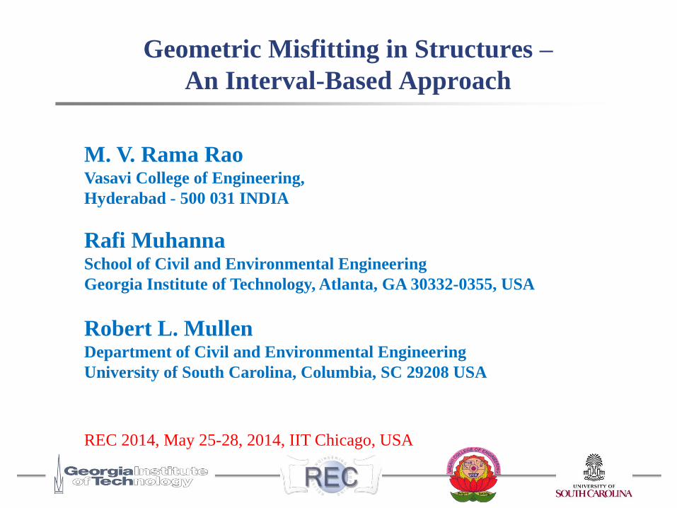
Geometric Misfitting in Structures –
An Interval-Based Approach
M. V. Rama RaoVasavi College of Engineering,
Hyderabad - 500 031 INDIA
Rafi MuhannaSchool of Civil and Environmental Engineering
Georgia Institute of Technology, Atlanta, GA 30332-0355, USA
Robert L. MullenDepartment of Civil and Environmental Engineering
University of South Carolina, Columbia, SC 29208 USA
REC 2014, May 25-28, 2014, IIT Chicago, USA
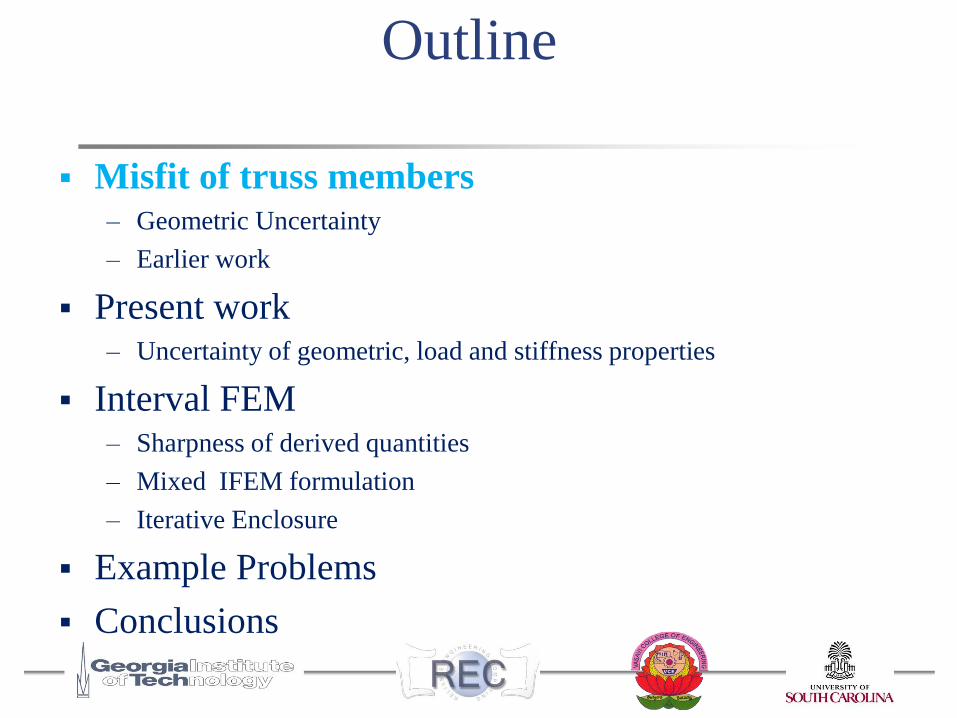
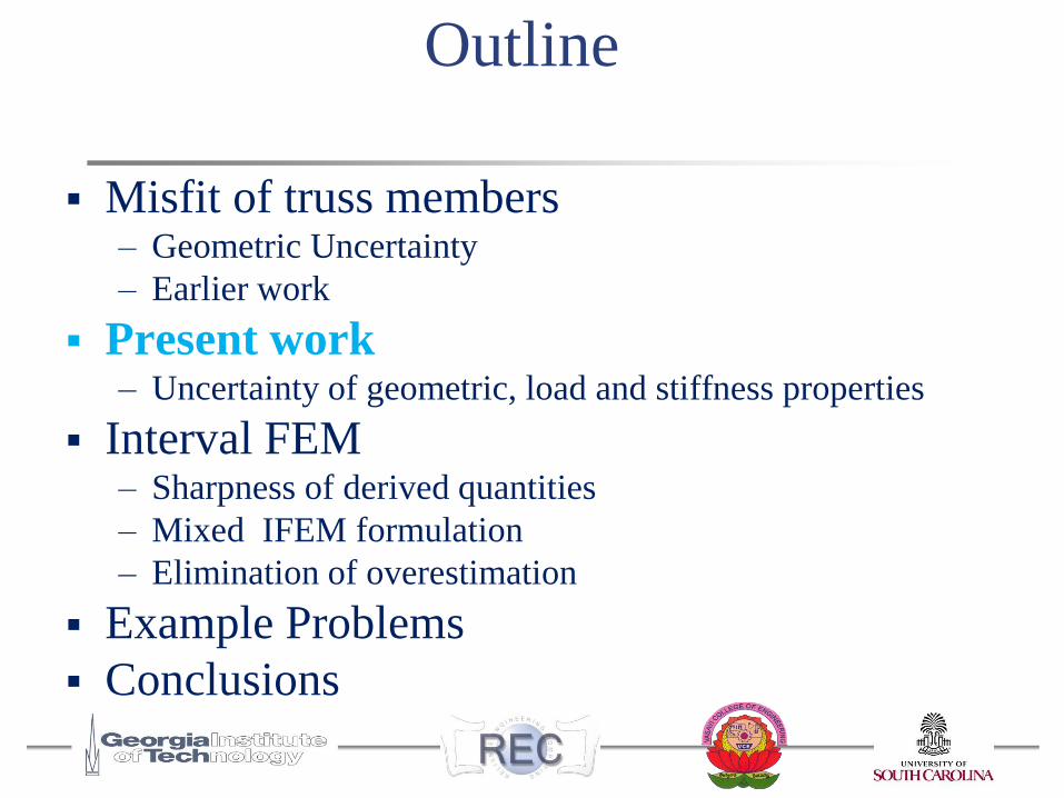
Outline
Misfit of truss members– Geometric Uncertainty
– Earlier work
Present work – Uncertainty of geometric, load and stiffness properties
Interval FEM– Sharpness of derived quantities
– Mixed IFEM formulation
– Iterative Enclosure
Example Problems
Conclusions
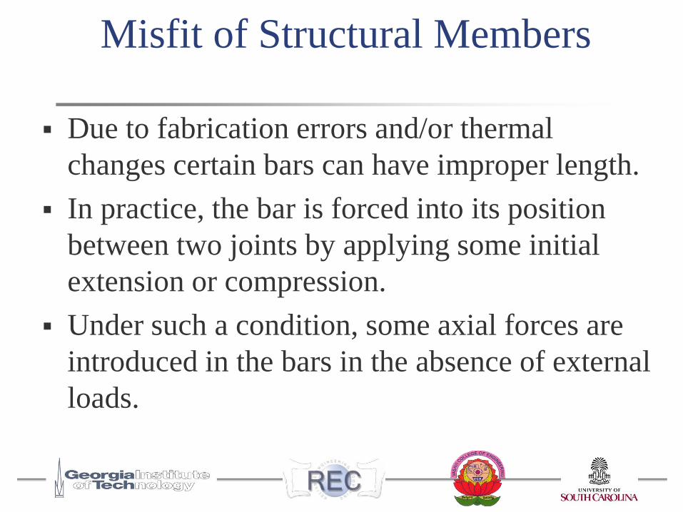
Misfit of Structural Members
Due to fabrication errors and/or thermal
changes certain bars can have improper length.
In practice, the bar is forced into its position
between two joints by applying some initial
extension or compression.
Under such a condition, some axial forces are
introduced in the bars in the absence of external
loads.
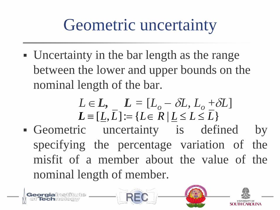
Uncertainty in the bar length as the range
between the lower and upper bounds on the
nominal length of the bar.
L L, L = [Lo L, Lo +L]
Geometric uncertainty is defined by
specifying the percentage variation of the
misfit of a member about the value of the
nominal length of member.
[ , ] : { | } L L L R L L LL
Geometric uncertainty
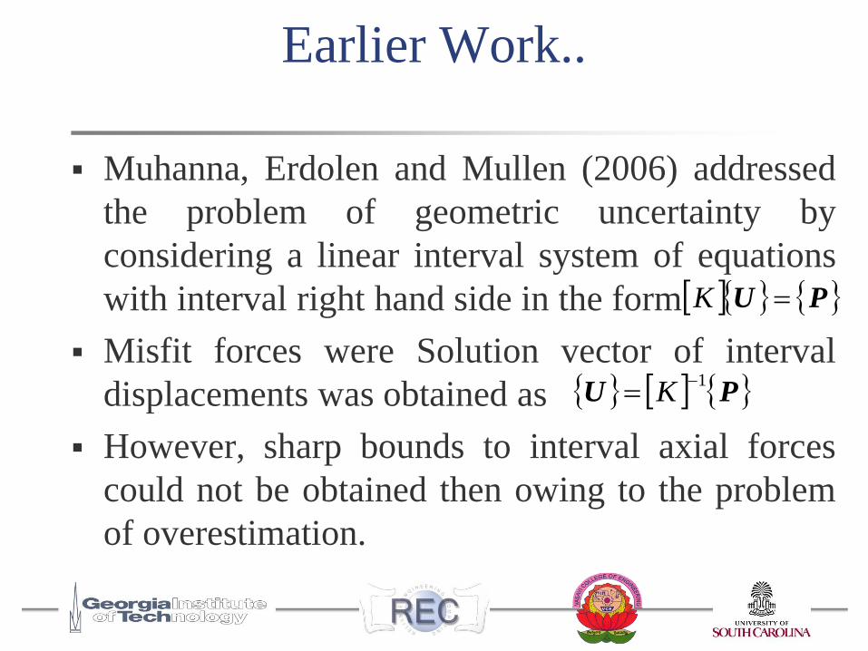
Earlier Work..
Muhanna, Erdolen and Mullen (2006) addressed
the problem of geometric uncertainty by
considering a linear interval system of equations
with interval right hand side in the form
Misfit forces were Solution vector of interval
displacements was obtained as
However, sharp bounds to interval axial forces
could not be obtained then owing to the problem
of overestimation.
PU1
K
PU K
Outline
Misfit of truss members– Geometric Uncertainty
– Earlier work
Present work – Uncertainty of geometric, load and stiffness properties
Interval FEM– Sharpness of derived quantities
– Mixed IFEM formulation
– Elimination of overestimation
Example Problems
Conclusions
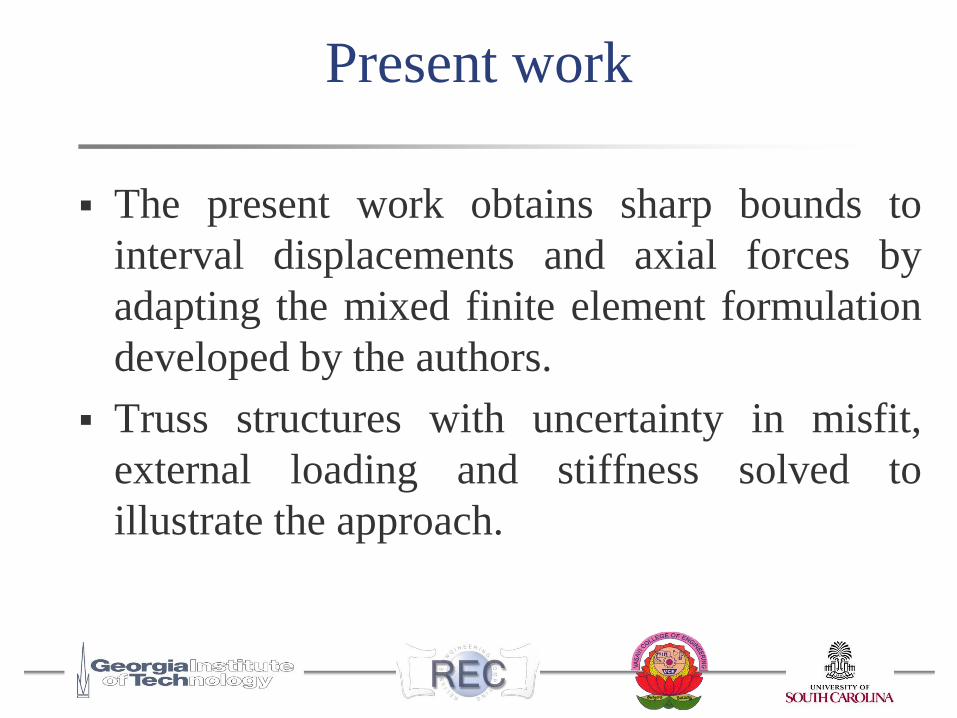
Present work
The present work obtains sharp bounds to
interval displacements and axial forces by
adapting the mixed finite element formulation
developed by the authors.
Truss structures with uncertainty in misfit,
external loading and stiffness solved to
illustrate the approach.
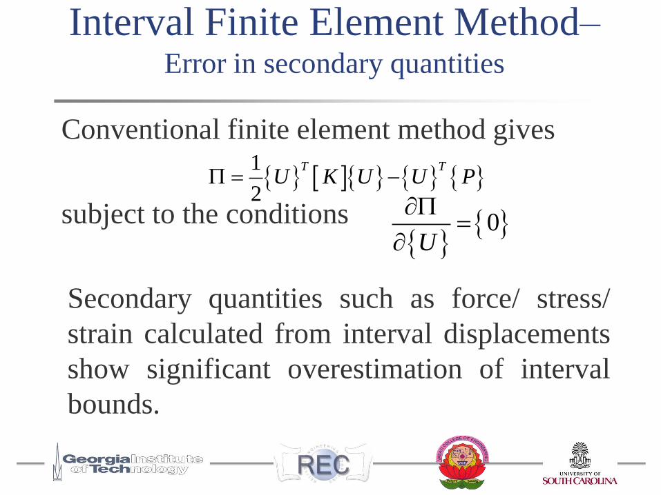
Interval Finite Element Method–Error in secondary quantities
Conventional finite element method gives
subject to the conditions
Secondary quantities such as force/ stress/
strain calculated from interval displacements
show significant overestimation of interval
bounds.
1
2
T TU K U U P
0
U
Mixed interval finite element formulation
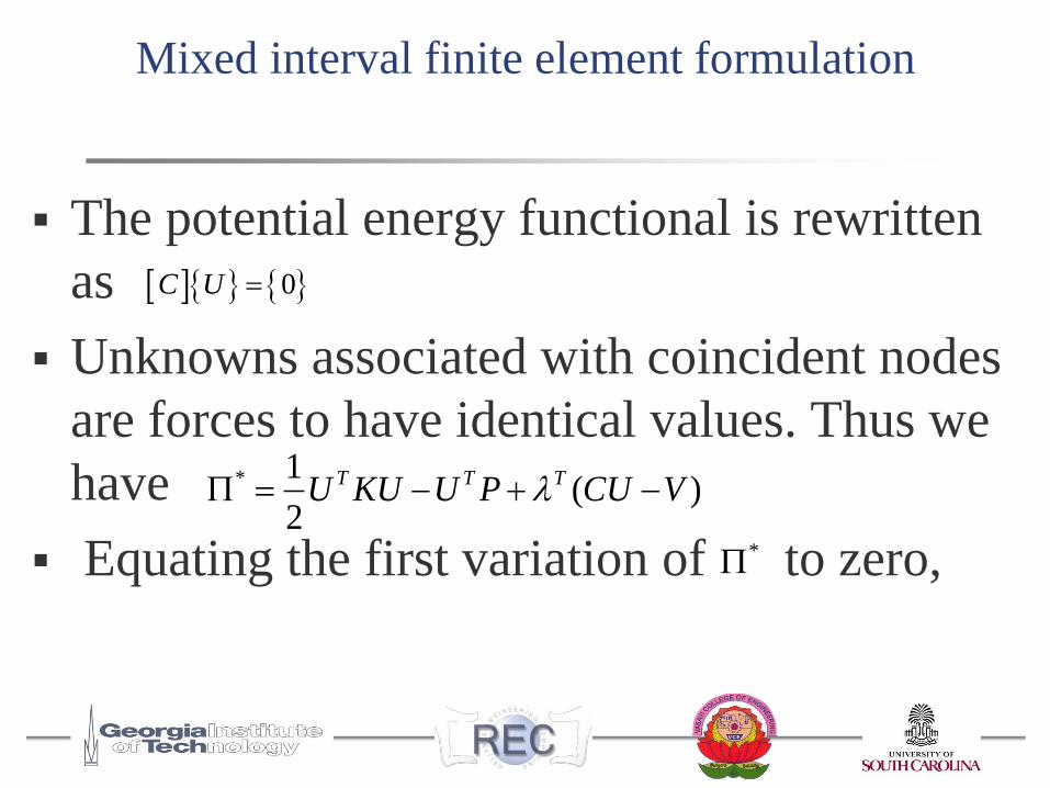
The potential energy functional is rewritten
as
Unknowns associated with coincident nodes
are forces to have identical values. Thus we
have
Equating the first variation of to zero,
* 1( )
2
T T TU KU U P CU V
*
0C U
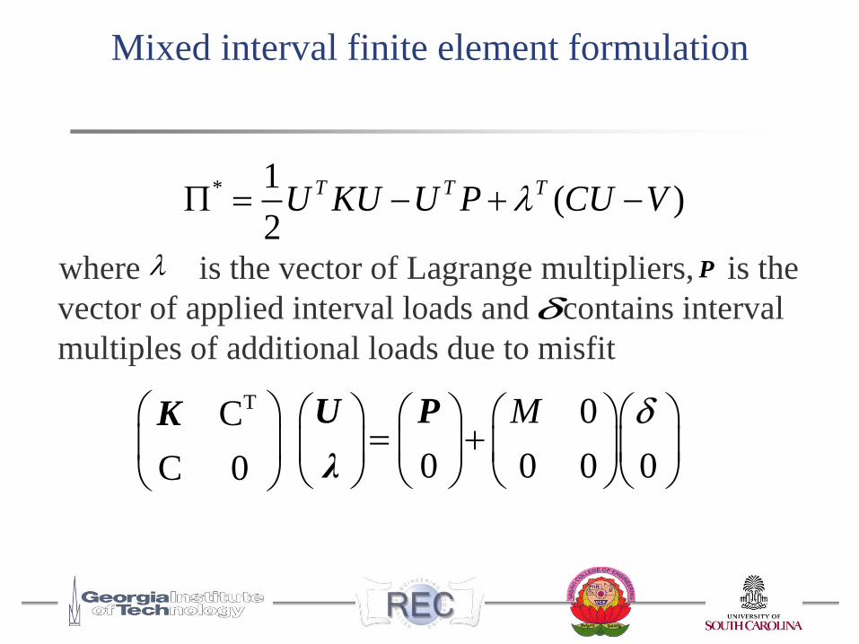
Mixed interval finite element formulation
where is the vector of Lagrange multipliers, is the
vector of applied interval loads and contains interval
multiples of additional loads due to misfit
* 1( )
2
T T TU KU U P CU V
T 0C
0 0 0 0C 0
M
U PK
λ
P
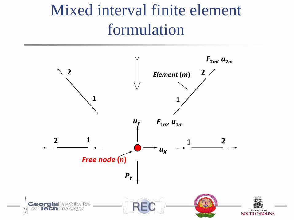
Mixed interval finite element
formulation
Element (m)
uY
uX
F2m, u2m
F1m, u1m
PY
2 2
12 1 2
1 1
Free node (n)
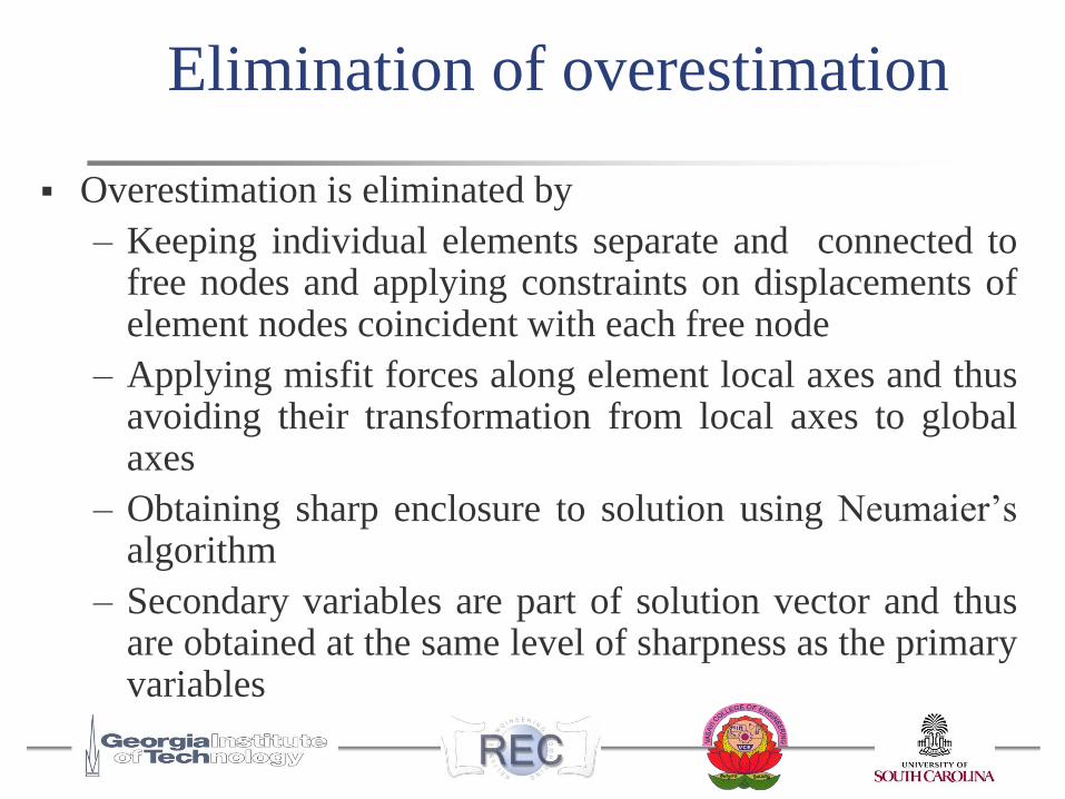
Elimination of overestimation
Overestimation is eliminated by
– Keeping individual elements separate and connected tofree nodes and applying constraints on displacements ofelement nodes coincident with each free node
– Applying misfit forces along element local axes and thusavoiding their transformation from local axes to globalaxes
– Obtaining sharp enclosure to solution using Neumaier’salgorithm
– Secondary variables are part of solution vector and thusare obtained at the same level of sharpness as the primaryvariables
Outline
Misfit of truss members– Geometric Uncertainty
– Earlier work
Present work – Uncertainty of geometric, load and stiffness properties
Interval FEM– Sharpness of derived quantities
– Mixed IFEM formulation
– Elimination of overestimation
Example Problems
Conclusions
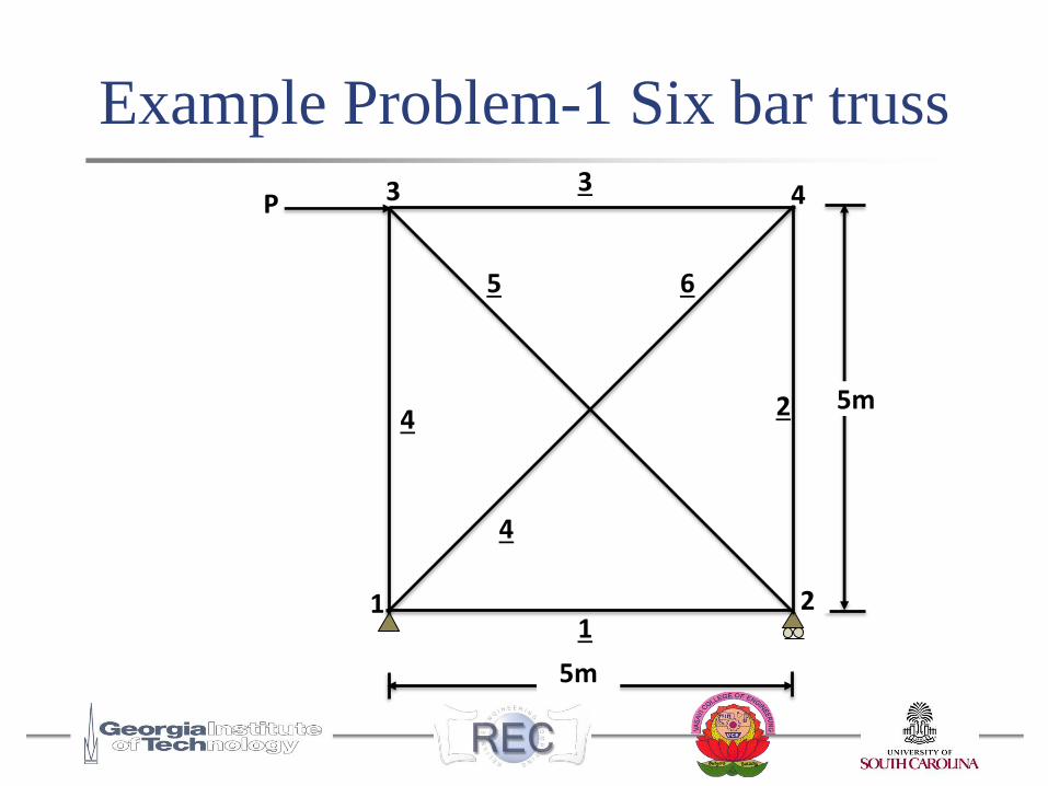
Example Problem-1 Six bar truss
5m
P
65
4 2
1
43
1
4
2
3
5m
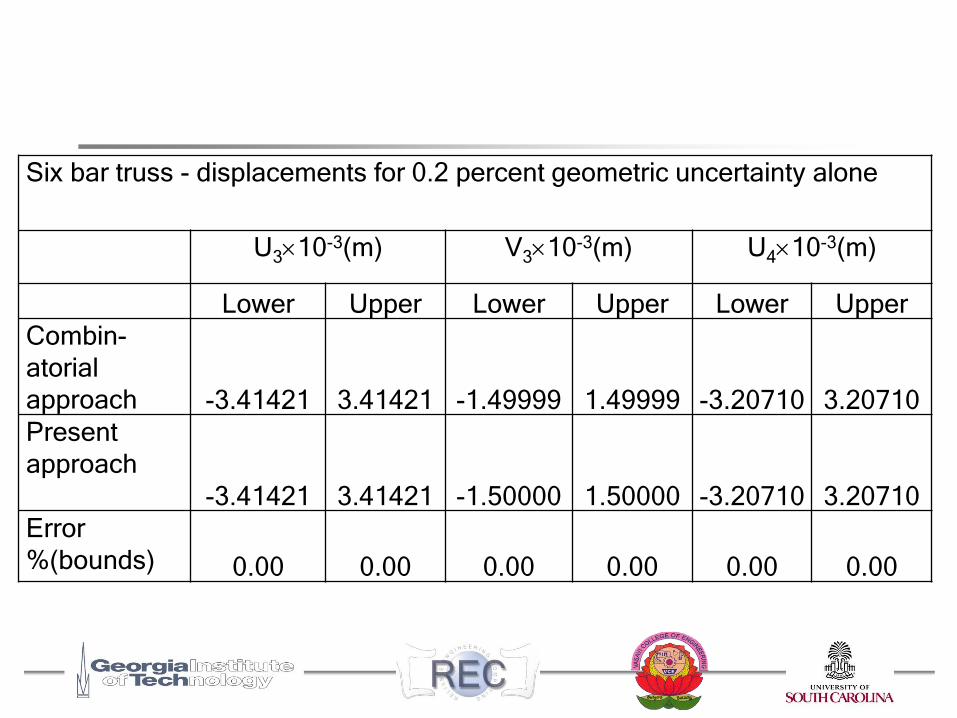
Six bar truss - displacements for 0.2 percent geometric uncertainty alone
U310-3(m) V310-3(m) U410-3(m)
Lower Upper Lower Upper Lower Upper
Combin-
atorial
approach -3.41421 3.41421 -1.49999 1.49999 -3.20710 3.20710
Present
approach
-3.41421 3.41421 -1.50000 1.50000 -3.20710 3.20710
Error
%(bounds) 0.00 0.00 0.00 0.00 0.00 0.00
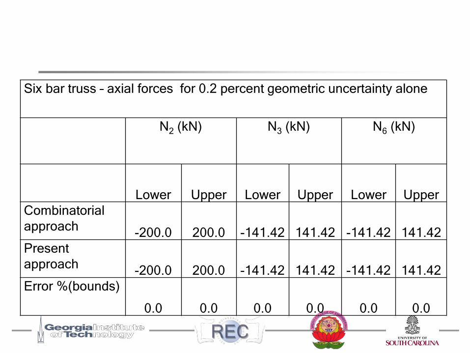
Six bar truss – axial forces for 0.2 percent geometric uncertainty alone
N2 (kN) N3 (kN) N6 (kN)
Lower Upper Lower Upper Lower Upper
Combinatorial
approach-200.0 200.0 -141.42 141.42 -141.42 141.42
Present
approach-200.0 200.0 -141.42 141.42 -141.42 141.42
Error %(bounds)
0.0 0.0 0.0 0.0 0.0 0.0
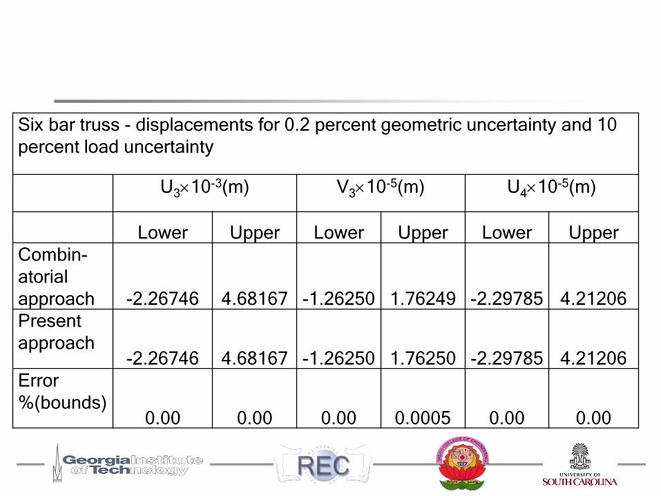
Six bar truss - displacements for 0.2 percent geometric uncertainty and 10
percent load uncertainty
U310-3(m) V310-5(m) U410-5(m)
Lower Upper Lower Upper Lower Upper
Combin-
atorial
approach -2.26746 4.68167 -1.26250 1.76249 -2.29785 4.21206
Present
approach-2.26746 4.68167 -1.26250 1.76250 -2.29785 4.21206
Error
%(bounds)0.00 0.00 0.00 0.0005 0.00 0.00
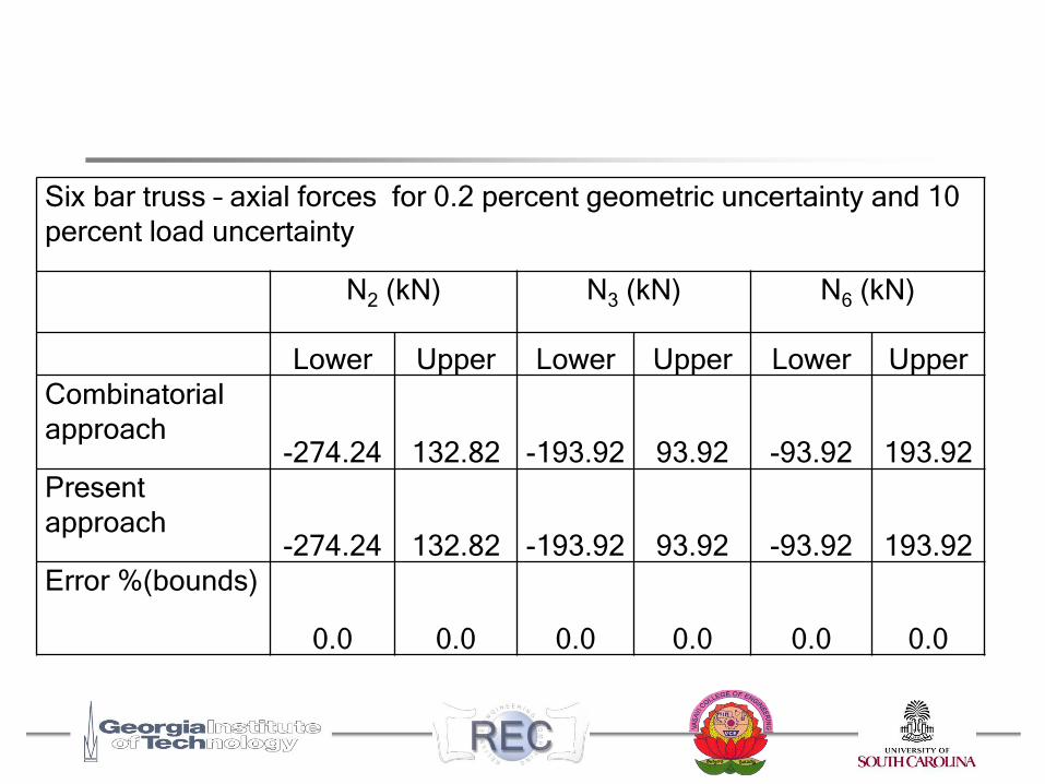
Six bar truss – axial forces for 0.2 percent geometric uncertainty and 10
percent load uncertainty
N2 (kN) N3 (kN) N6 (kN)
Lower Upper Lower Upper Lower Upper
Combinatorial
approach-274.24 132.82 -193.92 93.92 -93.92 193.92
Present
approach-274.24 132.82 -193.92 93.92 -93.92 193.92
Error %(bounds)
0.0 0.0 0.0 0.0 0.0 0.0
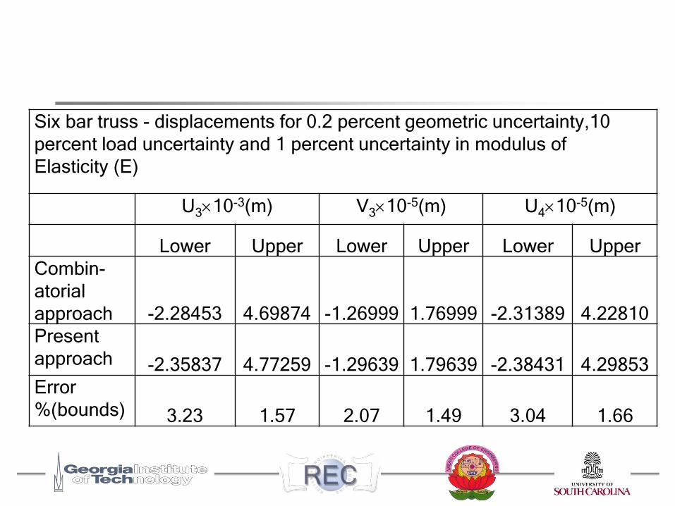
Six bar truss - displacements for 0.2 percent geometric uncertainty,10
percent load uncertainty and 1 percent uncertainty in modulus of
Elasticity (E)
U310-3(m) V310-5(m) U410-5(m)
Lower Upper Lower Upper Lower Upper
Combin-
atorial
approach -2.28453 4.69874 -1.26999 1.76999 -2.31389 4.22810
Present
approach -2.35837 4.77259 -1.29639 1.79639 -2.38431 4.29853
Error
%(bounds) 3.23 1.57 2.07 1.49 3.04 1.66
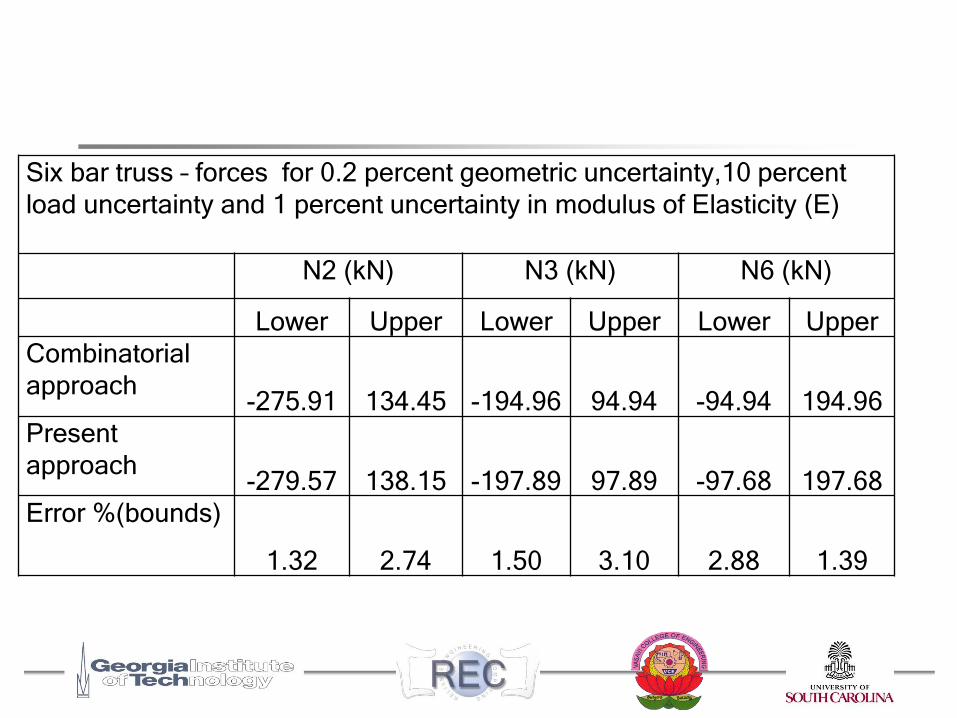
Six bar truss – forces for 0.2 percent geometric uncertainty,10 percent
load uncertainty and 1 percent uncertainty in modulus of Elasticity (E)
N2 (kN) N3 (kN) N6 (kN)
Lower Upper Lower Upper Lower Upper
Combinatorial
approach-275.91 134.45 -194.96 94.94 -94.94 194.96
Present
approach-279.57 138.15 -197.89 97.89 -97.68 197.68
Error %(bounds)
1.32 2.74 1.50 3.10 2.88 1.39
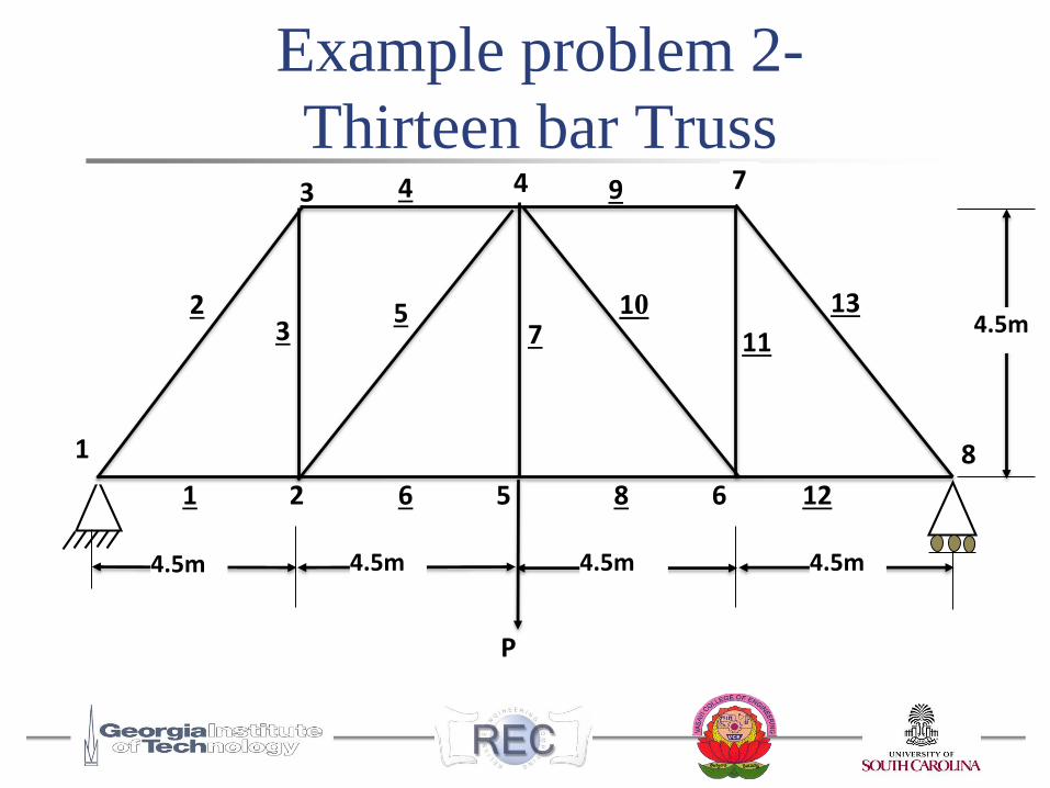
Example problem 2-
Thirteen bar Truss
P
4
8
12
13
11
10
9
8
7
6
53
4
2
1
73
652
1
4.5m 4.5mm4.5m 4.5m 4.5m
4.5m
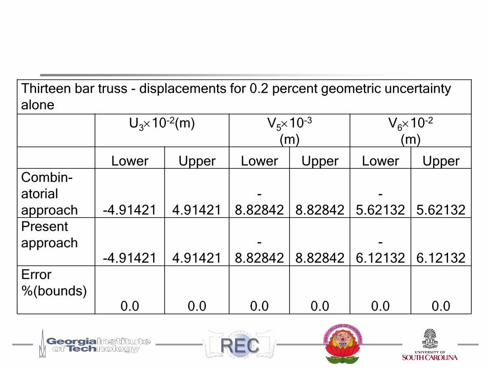
Thirteen bar truss - displacements for 0.2 percent geometric uncertainty
alone
U310-2(m) V510-3
(m)
V610-2
(m)
Lower Upper Lower Upper Lower Upper
Combin-
atorial
approach -4.91421 4.91421
-
8.82842 8.82842
-
5.62132 5.62132
Present
approach-4.91421 4.91421
-
8.82842 8.82842
-
6.12132 6.12132
Error
%(bounds)0.0 0.0 0.0 0.0 0.0 0.0
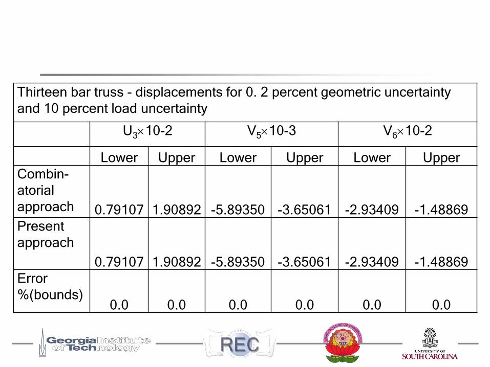
Thirteen bar truss - displacements for 0. 2 percent geometric uncertainty
and 10 percent load uncertainty
U310-2 V510-3 V610-2
Lower Upper Lower Upper Lower Upper
Combin-
atorial
approach 0.79107 1.90892 -5.89350 -3.65061 -2.93409 -1.48869
Present
approach
0.79107 1.90892 -5.89350 -3.65061 -2.93409 -1.48869
Error
%(bounds)0.0 0.0 0.0 0.0 0.0 0.0
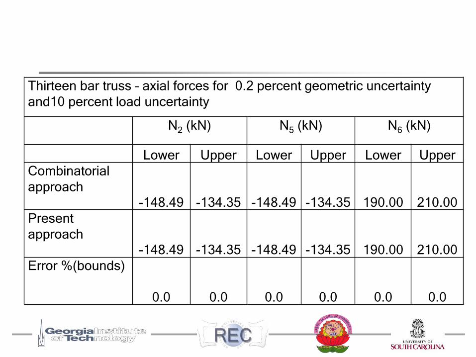
Thirteen bar truss – axial forces for 0.2 percent geometric uncertainty
and10 percent load uncertainty
N2 (kN) N5 (kN) N6 (kN)
Lower Upper Lower Upper Lower Upper
Combinatorial
approach
-148.49 -134.35 -148.49 -134.35 190.00 210.00
Present
approach
-148.49 -134.35 -148.49 -134.35 190.00 210.00
Error %(bounds)
0.0 0.0 0.0 0.0 0.0 0.0
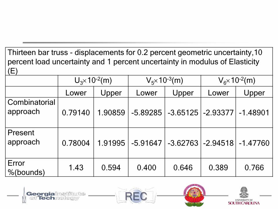
Thirteen bar truss - displacements for 0.2 percent geometric uncertainty,10
percent load uncertainty and 1 percent uncertainty in modulus of Elasticity
(E)
U310-2(m) V510-3(m) V610-2(m)
Lower Upper Lower Upper Lower Upper
Combinatorial
approach 0.79140 1.90859 -5.89285 -3.65125 -2.93377 -1.48901
Present
approach 0.78004 1.91995 -5.91647 -3.62763 -2.94518 -1.47760
Error
%(bounds)1.43 0.594 0.400 0.646 0.389 0.766
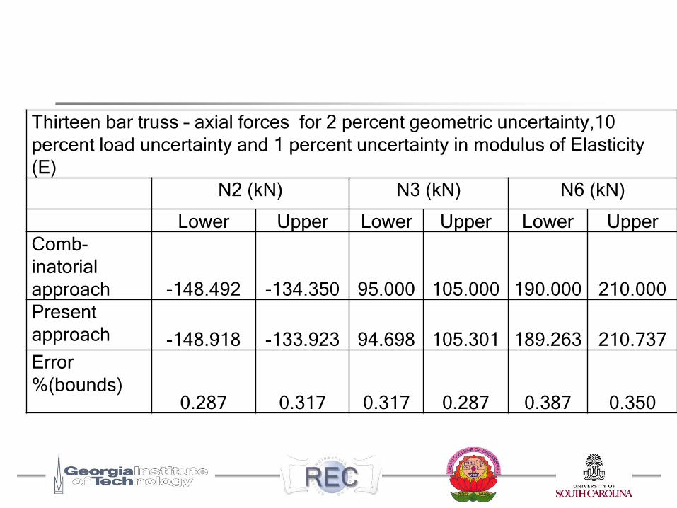
Thirteen bar truss – axial forces for 2 percent geometric uncertainty,10
percent load uncertainty and 1 percent uncertainty in modulus of Elasticity
(E)
N2 (kN) N3 (kN) N6 (kN)
Lower Upper Lower Upper Lower Upper
Comb-
inatorial
approach -148.492 -134.350 95.000 105.000 190.000 210.000
Present
approach -148.918 -133.923 94.698 105.301 189.263 210.737
Error
%(bounds)0.287 0.317 0.317 0.287 0.387 0.350
Outline
Misfit of truss members– Geometric Uncertainty
– Earlier work
Present work – Uncertainty of geometric, load and stiffness properties
Interval FEM– Sharpness of derived quantities
– Mixed IFEM formulation
– Iterative Enclosure
Results
Summary
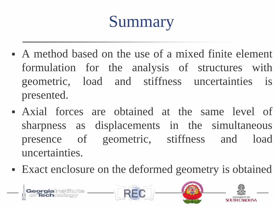
Summary
A method based on the use of a mixed finite element
formulation for the analysis of structures with
geometric, load and stiffness uncertainties is
presented.
Axial forces are obtained at the same level of
sharpness as displacements in the simultaneous
presence of geometric, stiffness and load
uncertainties.
Exact enclosure on the deformed geometry is obtained

Let us all be together.
Let us share everything
together. Let us carry out tasks
with collective effort.
Let our minds work together to
acquire knowledge.
Let us not harm each other.
Let peace pervade Universe.
-(Shanti Mantra ~3000 BC
- INDIA)
![arXiv:1108.4213v3 [math.NA] 7 Sep 201210 West 32nd Str, Bld E1, Room 208 Chicago, Illinois, USA 60616 igor@math.iit.edu, fasshauer@iit.edu and qye3@iit.edu Updated Version in International](https://img.pdfslide.us/doc/110x75/60b38ee9b2fdcc2e9964f1d3/arxiv11084213v3-mathna-7-sep-2012-10-west-32nd-str-bld-e1-room-208-chicago.jpg)