Embed Size (px)
Citation preview
8/3/2019 Geometric Dimension Ing Tolerancing Part2
http://slidepdf.com/reader/full/geometric-dimension-ing-tolerancing-part2 1/36
Geometric dimensioning &eometric dimensioning &
tolerancingolerancing (Part 2)Part 2)
KCEC 1101
8/3/2019 Geometric Dimension Ing Tolerancing Part2
http://slidepdf.com/reader/full/geometric-dimension-ing-tolerancing-part2 2/36
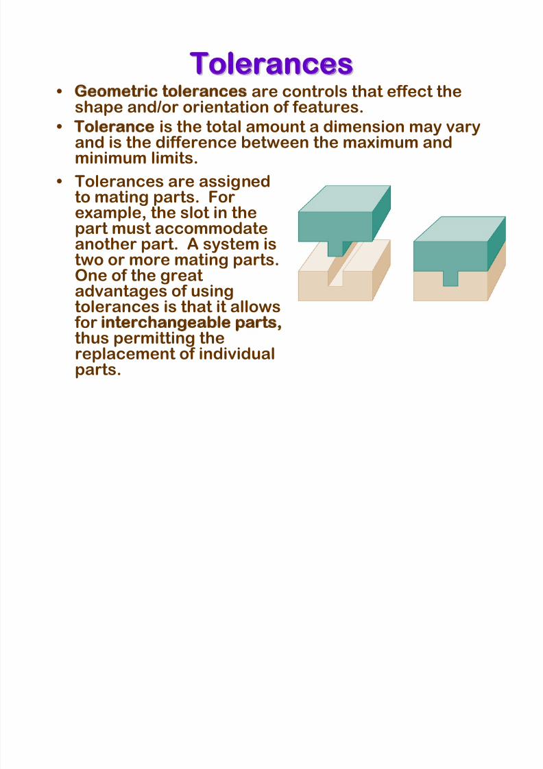
Tolerancesolerances• Geometric tolerances are controls that effect theshape and/or orientation of features.
• Tolerance is the total amount a dimension may vary
and is the difference between the maximum andminimum limits.
• Tolerances are assignedto mating parts. For
example, the slot in thepart must accommodateanother part. A system istwo or more mating parts.One of the great
advantages of usingtolerances is that it allows for interchangeable parts,thus permitting thereplacement of individualparts.
8/3/2019 Geometric Dimension Ing Tolerancing Part2
http://slidepdf.com/reader/full/geometric-dimension-ing-tolerancing-part2 3/36
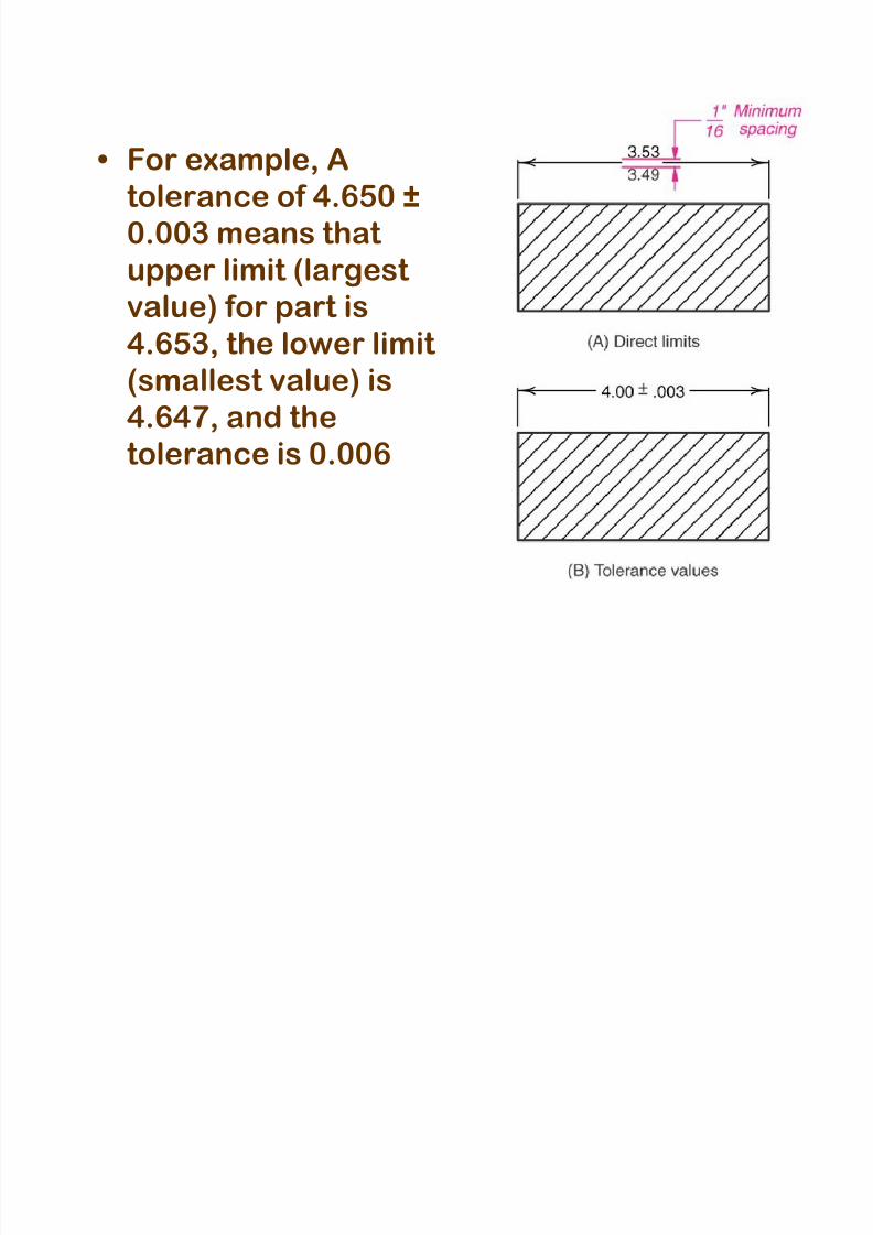
• For example, A
tolerance of 4.650 ±
0.003 means that upper limit (largest
value) for part is
4.653, the lower limit (smallest value) is
4.647, and the
tolerance is 0.006
8/3/2019 Geometric Dimension Ing Tolerancing Part2
http://slidepdf.com/reader/full/geometric-dimension-ing-tolerancing-part2 4/36
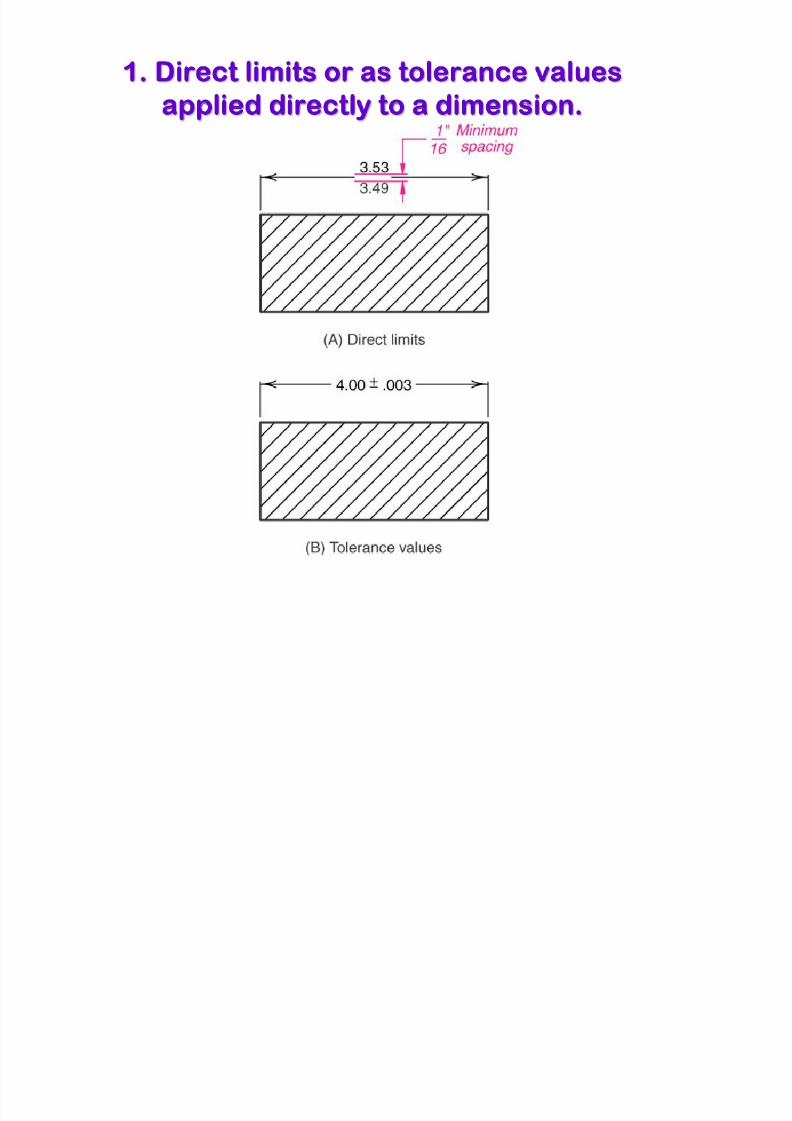
Tolerances are expressed as:olerances are expressed as:1. Direct limits, or as tolerance values
applied directly to a dimension2. Geometric tolerance
3. Notes referring to specific conditions
4. A general tolerance note in the title
block
8/3/2019 Geometric Dimension Ing Tolerancing Part2
http://slidepdf.com/reader/full/geometric-dimension-ing-tolerancing-part2 5/36
1. Direct limits or as tolerance values. Direct limits or as tolerance values
applied directly to a dimension.pplied directly to a dimension.
8/3/2019 Geometric Dimension Ing Tolerancing Part2
http://slidepdf.com/reader/full/geometric-dimension-ing-tolerancing-part2 6/36
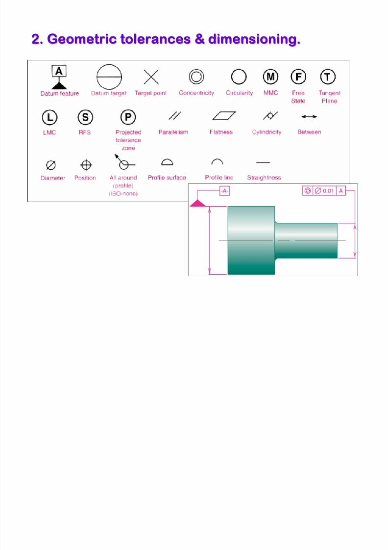
2. Geometric tolerances & dimensioning.. Geometric tolerances & dimensioning.
8/3/2019 Geometric Dimension Ing Tolerancing Part2
http://slidepdf.com/reader/full/geometric-dimension-ing-tolerancing-part2 7/36
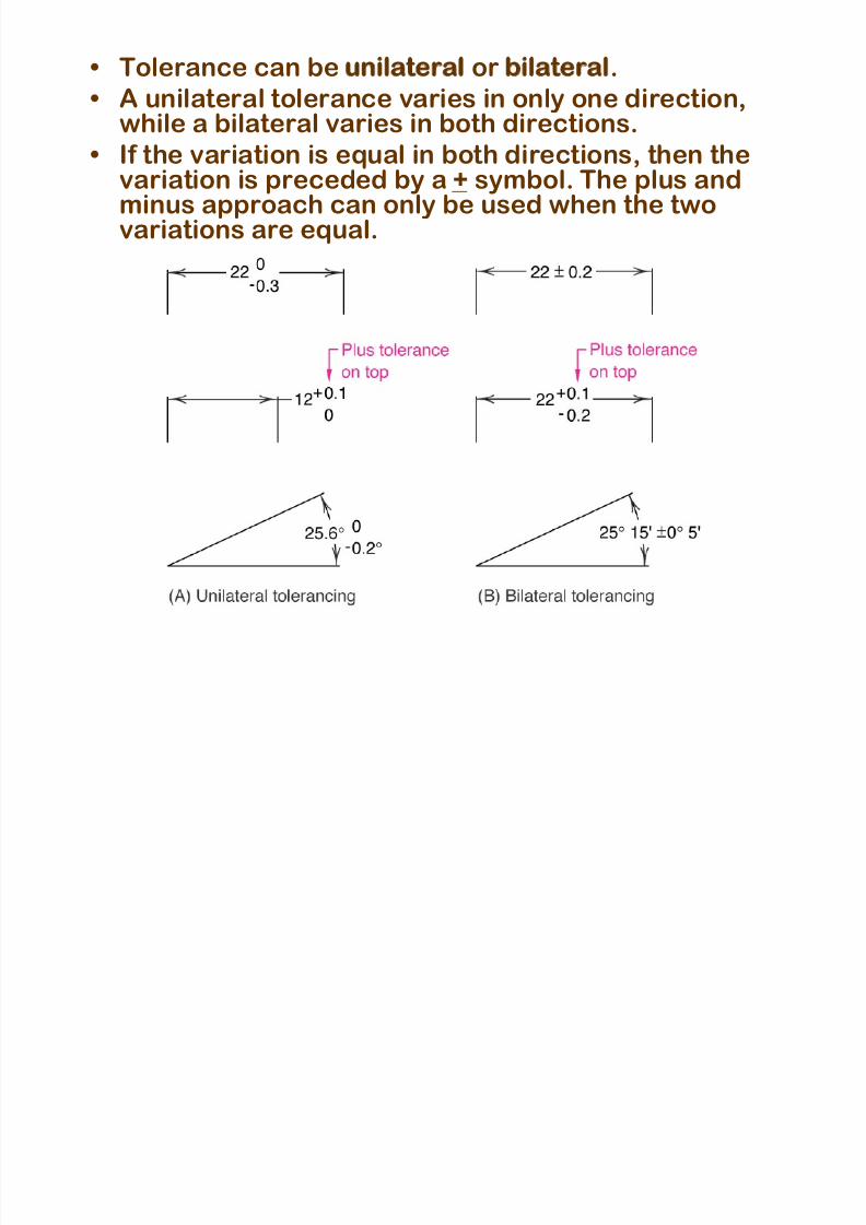
• Tolerance can be unilateral or bilateral.
• A unilateral tolerance varies in only one direction,while a bilateral varies in both directions.
• If the variation is equal in both directions, then thevariation is preceded by a + symbol. The plus andminus approach can only be used when the two
variations are equal.
8/3/2019 Geometric Dimension Ing Tolerancing Part2
http://slidepdf.com/reader/full/geometric-dimension-ing-tolerancing-part2 8/36
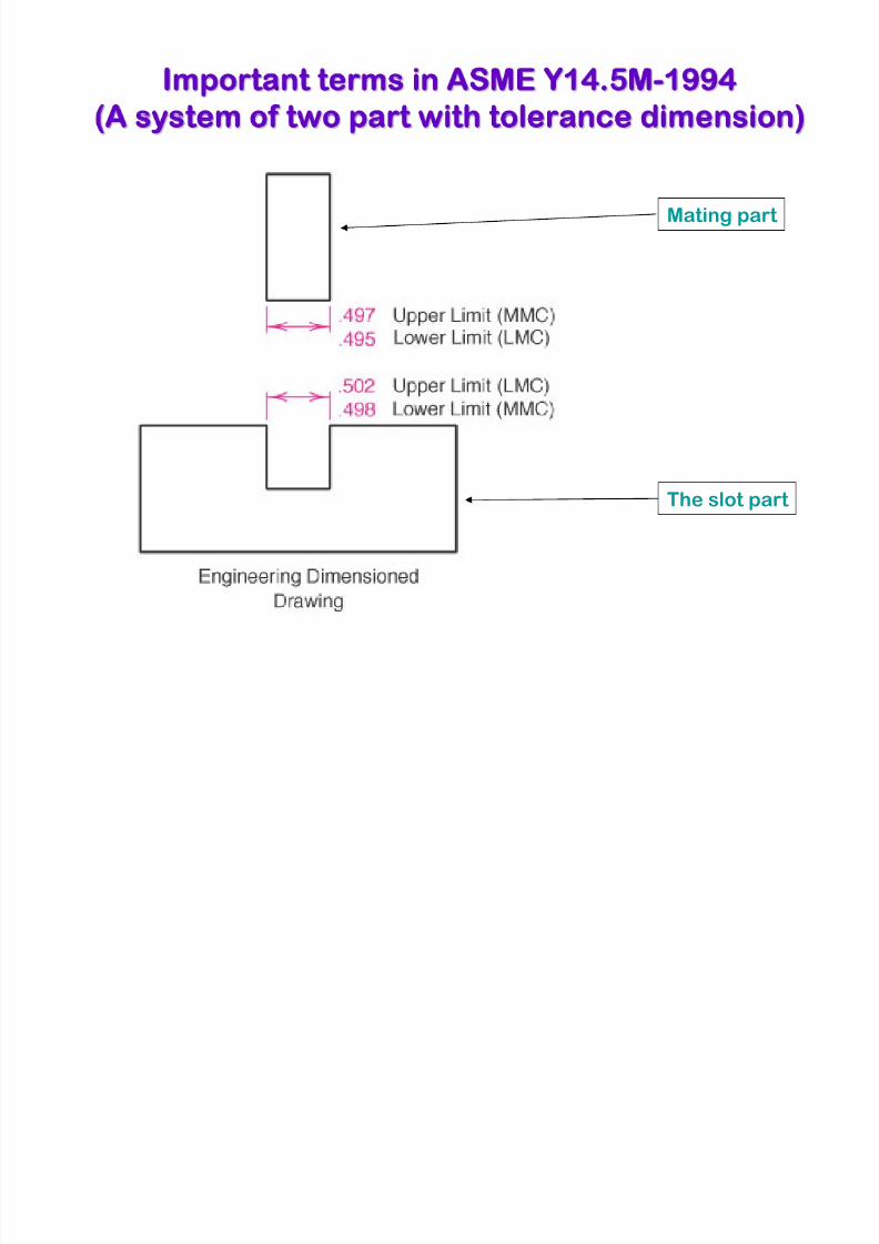
Important terms in ASME Y14.5Mmportant terms in ASME Y14.5M-1994994
(A system of two part with tolerance dimension)A system of two part with tolerance dimension)
Mating part
The slot part
8/3/2019 Geometric Dimension Ing Tolerancing Part2
http://slidepdf.com/reader/full/geometric-dimension-ing-tolerancing-part2 9/36
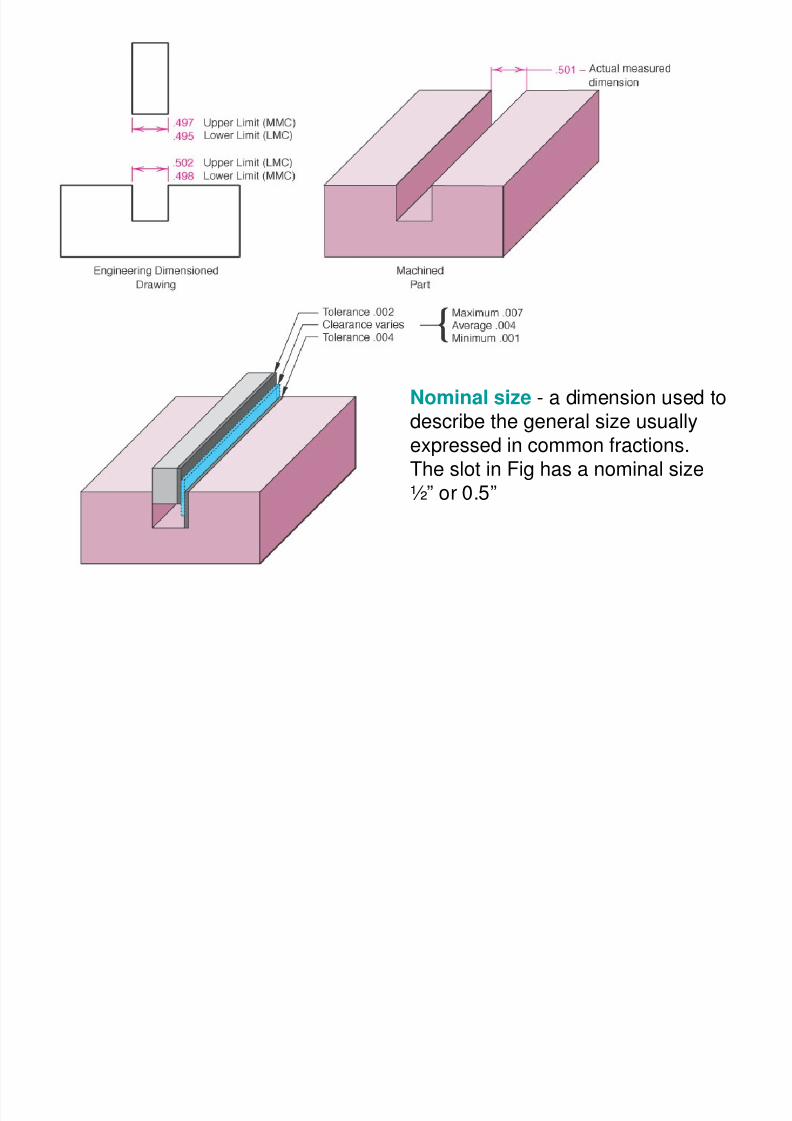
Nominal size - a dimension used to
describe the general size usuallyexpressed in common fractions.The slot in Fig has a nominal size½” or 0.5”

8/3/2019 Geometric Dimension Ing Tolerancing Part2
http://slidepdf.com/reader/full/geometric-dimension-ing-tolerancing-part2 10/36
Basic size the theoretical size used
as a starting point for the applicationof tolerances.The basic size of the slot in Fig is.500”.
8/3/2019 Geometric Dimension Ing Tolerancing Part2
http://slidepdf.com/reader/full/geometric-dimension-ing-tolerancing-part2 11/36
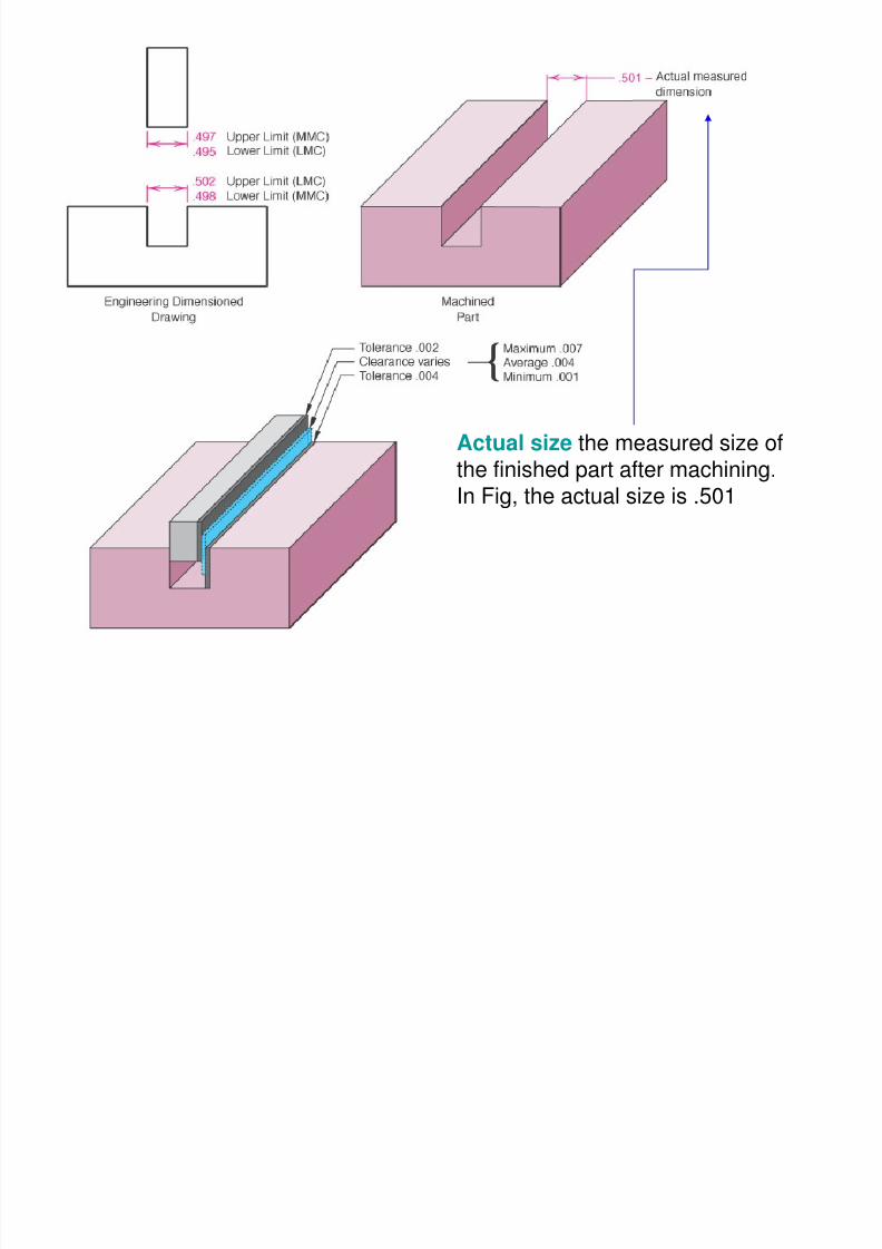
Actual size the measured size of
the finished part after machining.In Fig, the actual size is .501
8/3/2019 Geometric Dimension Ing Tolerancing Part2
http://slidepdf.com/reader/full/geometric-dimension-ing-tolerancing-part2 12/36
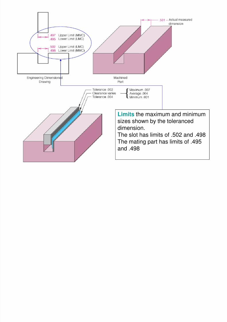
Limits the maximum and minimum
sizes shown by the toleranceddimension.The slot has limits of .502 and .498The mating part has limits of .495and .498
8/3/2019 Geometric Dimension Ing Tolerancing Part2
http://slidepdf.com/reader/full/geometric-dimension-ing-tolerancing-part2 13/36
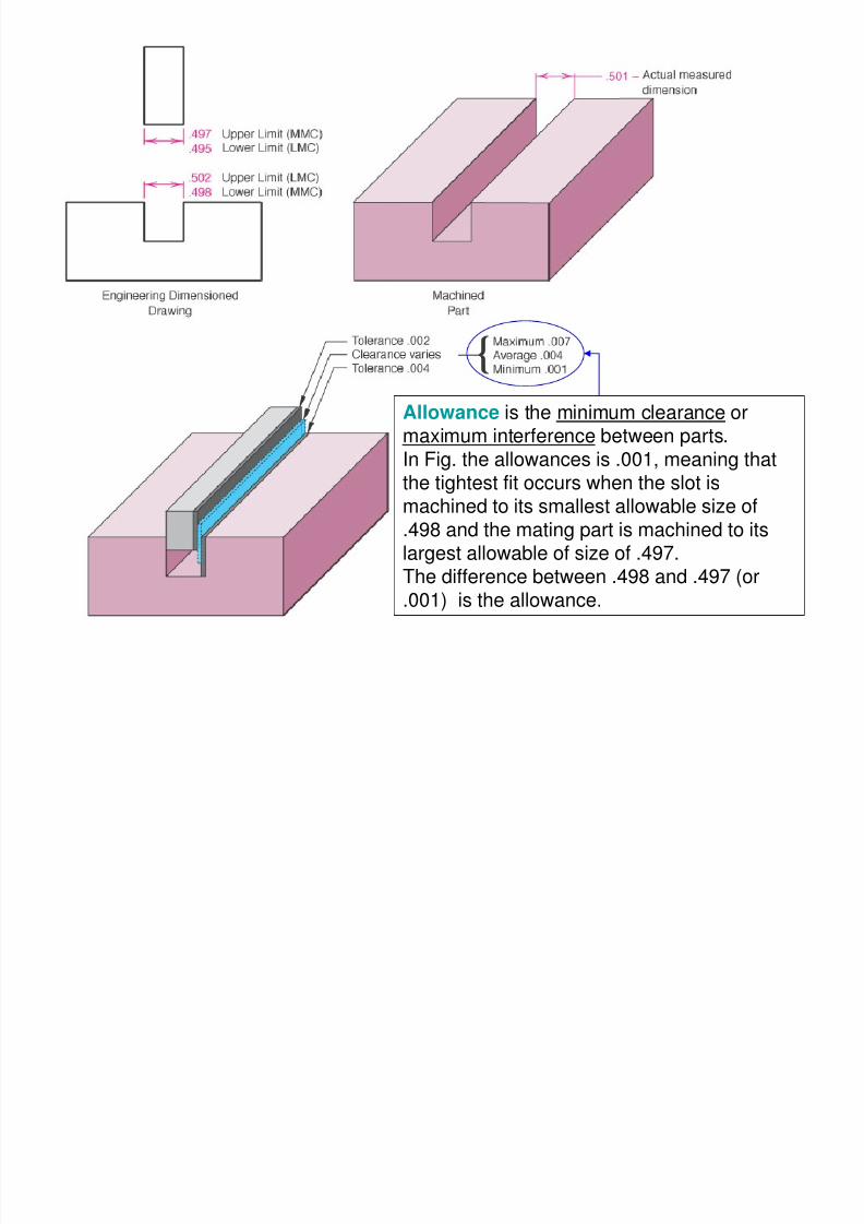
Allowance is the minimum clearance ormaximum interference between parts.
In Fig. the allowances is .001, meaning thatthe tightest fit occurs when the slot ismachined to its smallest allowable size of
.498 and the mating part is machined to itslargest allowable of size of .497.
The difference between .498 and .497 (or.001) is the allowance.
8/3/2019 Geometric Dimension Ing Tolerancing Part2
http://slidepdf.com/reader/full/geometric-dimension-ing-tolerancing-part2 14/36
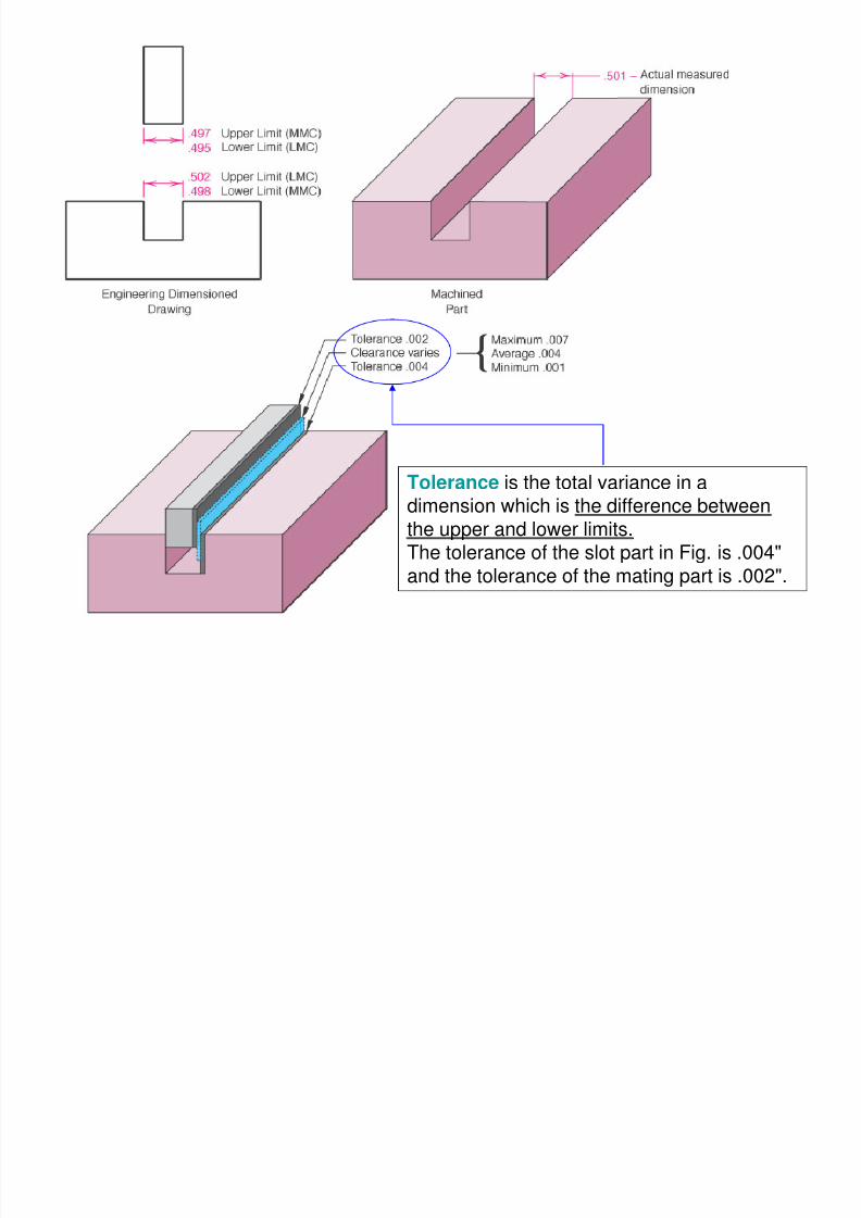
Tolerance is the total variance in adimension which is the difference between
the upper and lower limits.The tolerance of the slot part in Fig. is .004"
and the tolerance of the mating part is .002".
8/3/2019 Geometric Dimension Ing Tolerancing Part2
http://slidepdf.com/reader/full/geometric-dimension-ing-tolerancing-part2 15/36
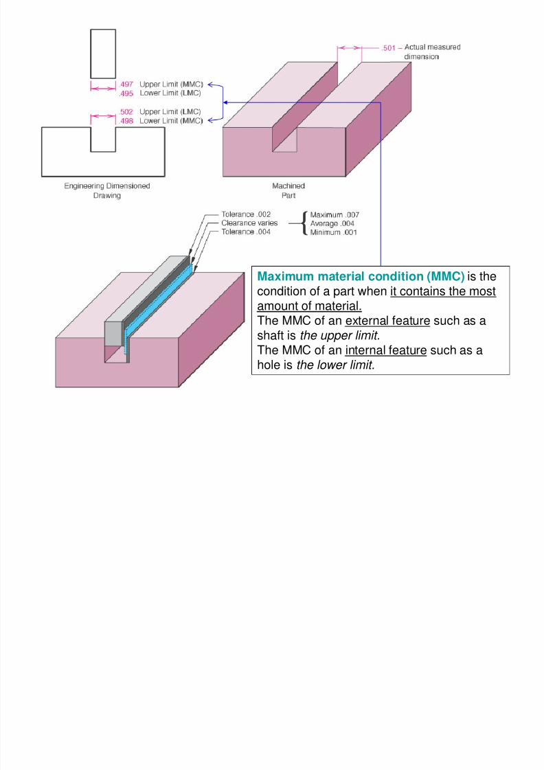
Maximum material condition (MMC) is the
condition of a part when it contains the mostamount of material.The MMC of an external feature such as a
shaft is the upper limit.
The MMC of an internal feature such as a
hole is the lower limit.
8/3/2019 Geometric Dimension Ing Tolerancing Part2
http://slidepdf.com/reader/full/geometric-dimension-ing-tolerancing-part2 16/36
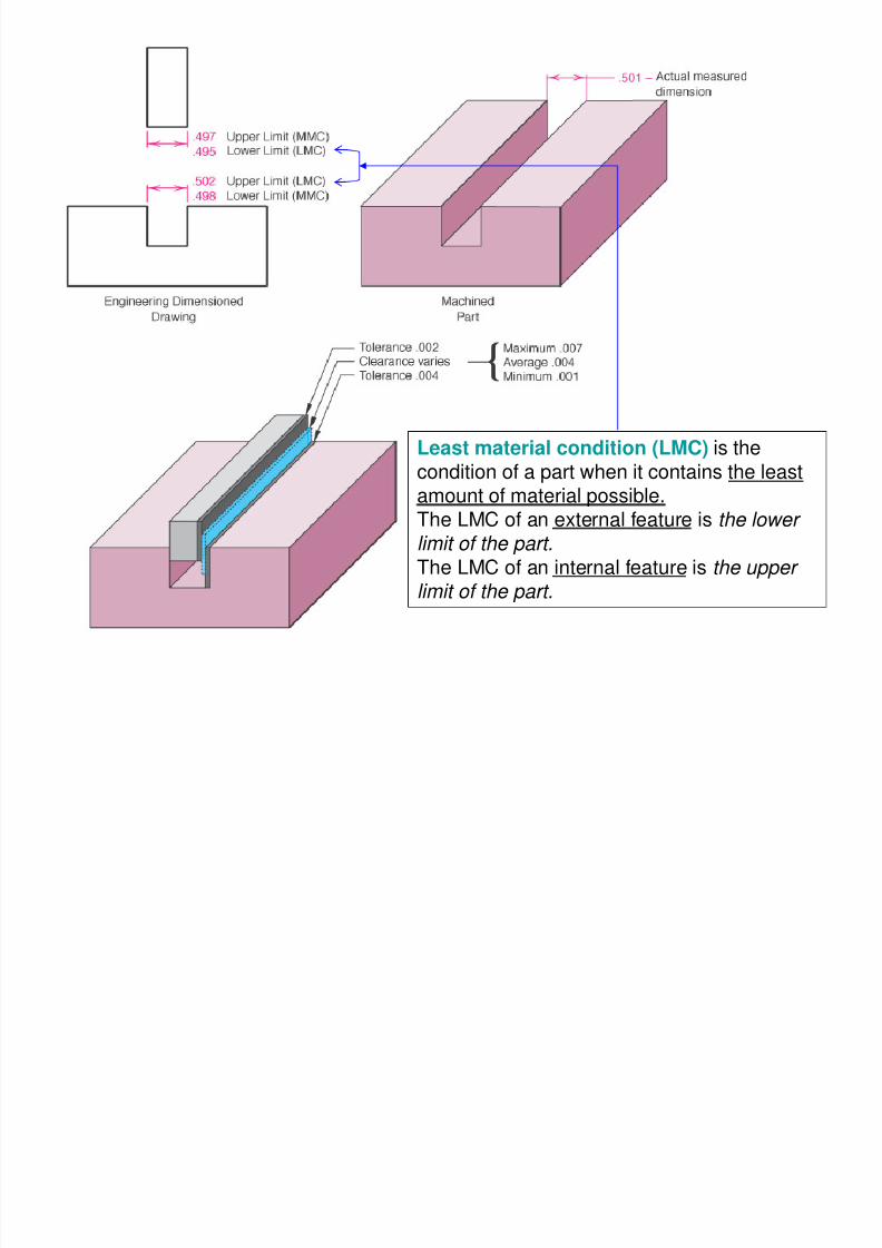
Least material condition (LMC) is the
condition of a part when it contains the leastamount of material possible.The LMC of an external feature is the lower
limit of the part.
The LMC of an internal feature is the upper
limit of the part.
8/3/2019 Geometric Dimension Ing Tolerancing Part2
http://slidepdf.com/reader/full/geometric-dimension-ing-tolerancing-part2 17/36
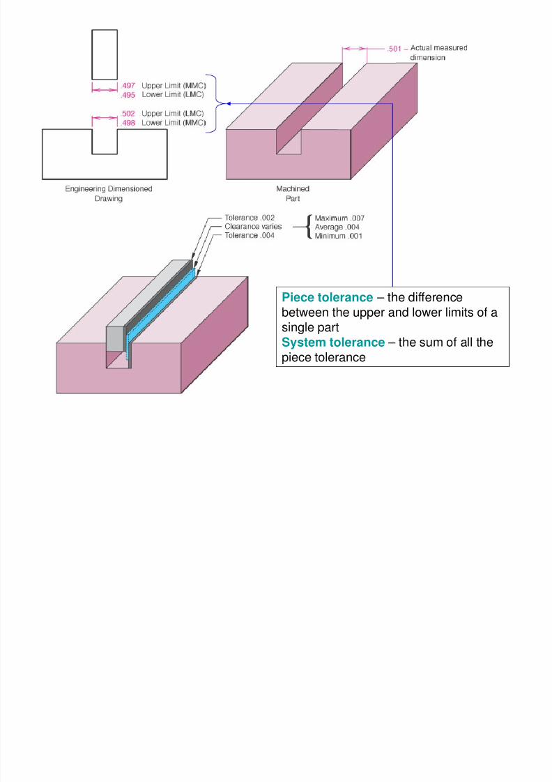
Piece tolerance – the differencebetween the upper and lower limits of asingle part
System tolerance – the sum of all the
piece tolerance
8/3/2019 Geometric Dimension Ing Tolerancing Part2
http://slidepdf.com/reader/full/geometric-dimension-ing-tolerancing-part2 18/36
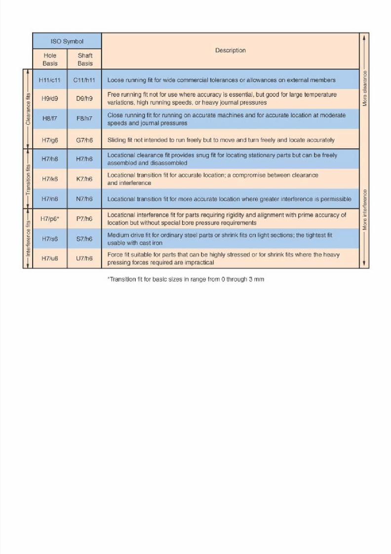
Fit typesit types
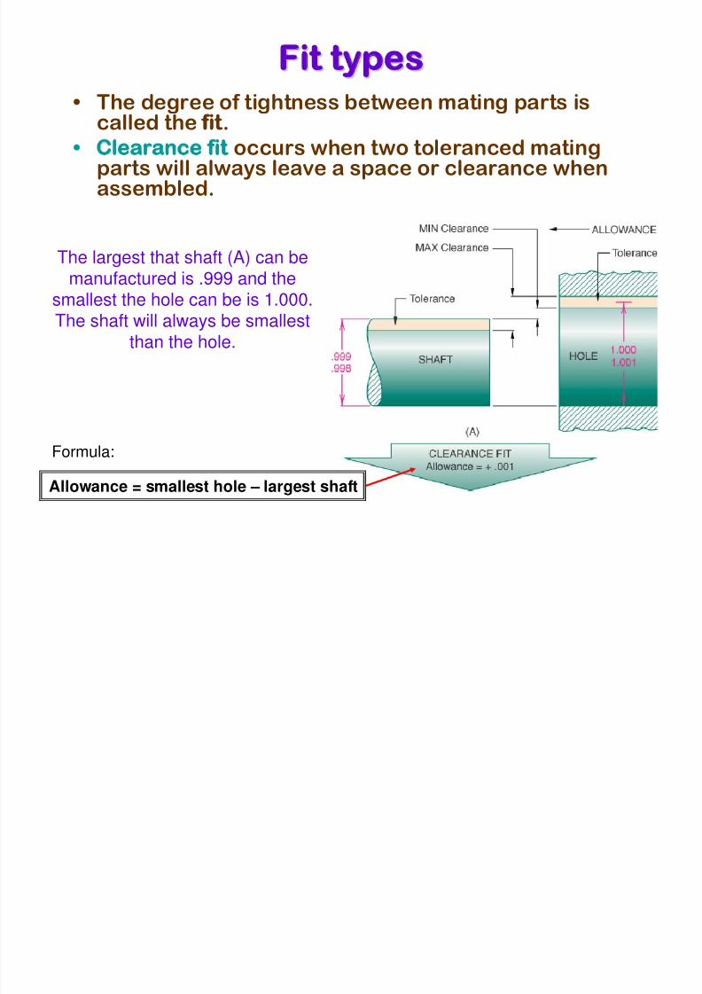
• The degree of tightness between mating parts iscalled the fit.
• Clearance fit occurs when two toleranced matingparts will always leave a space or clearance when
assembled.
The largest that shaft (A) can be
manufactured is .999 and thesmallest the hole can be is 1.000.The shaft will always be smallest
than the hole.
Allowance = smallest hole – largest shaft
Formula:
8/3/2019 Geometric Dimension Ing Tolerancing Part2
http://slidepdf.com/reader/full/geometric-dimension-ing-tolerancing-part2 19/36
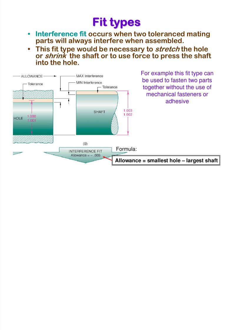
Fit typesit types• Interference fit occurs when two toleranced mating
parts will always interfere when assembled.
• This fit type would be necessary to stretch the holeor shrink the shaft or to use force to press the shaft
into the hole.For example this fit type canbe used to fasten two partstogether without the use of
mechanical fasteners oradhesive
Allowance = smallest hole – largest shaft
Formula:
8/3/2019 Geometric Dimension Ing Tolerancing Part2
http://slidepdf.com/reader/full/geometric-dimension-ing-tolerancing-part2 20/36
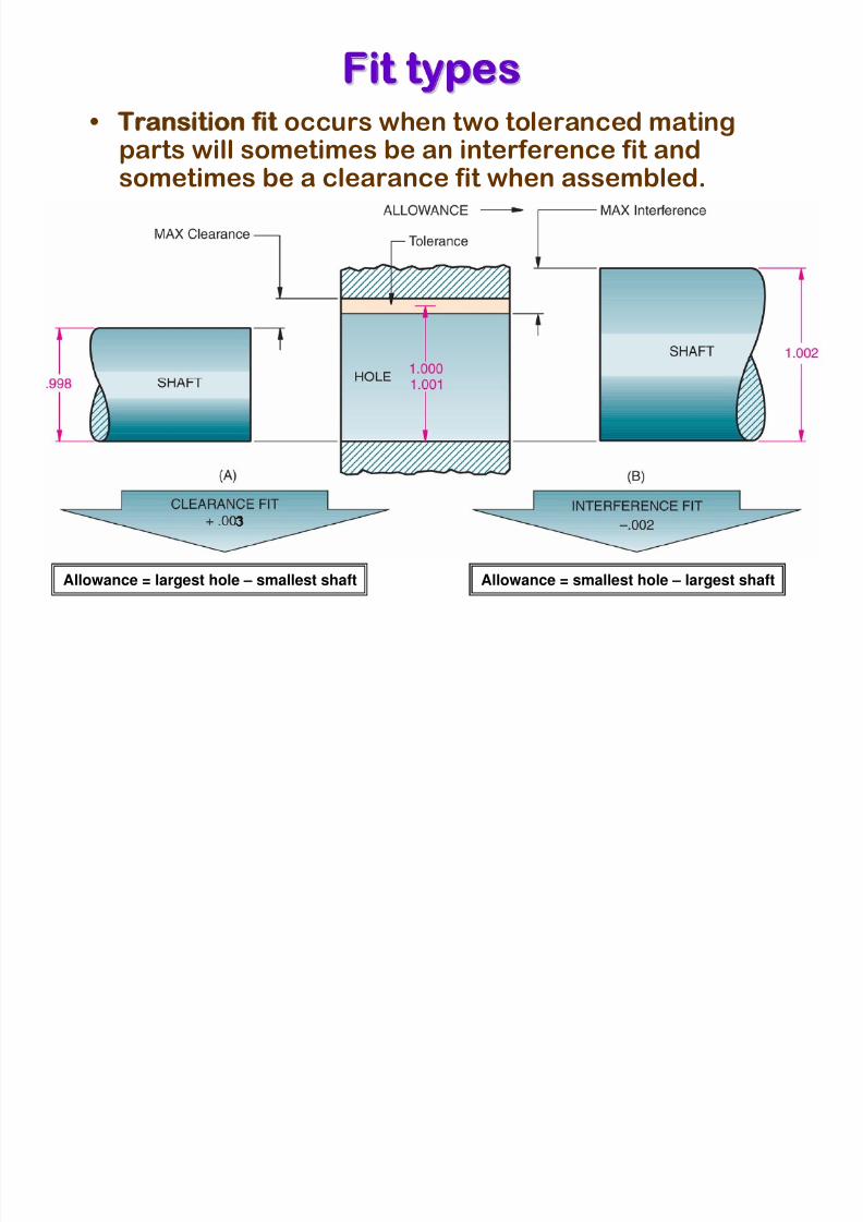
Fit typesit types
• Transition fit occurs when two toleranced matingparts will sometimes be an interference fit andsometimes be a clearance fit when assembled.
Allowance = largest hole – smallest shaft Allowance = smallest hole – largest shaft
8/3/2019 Geometric Dimension Ing Tolerancing Part2
http://slidepdf.com/reader/full/geometric-dimension-ing-tolerancing-part2 21/36
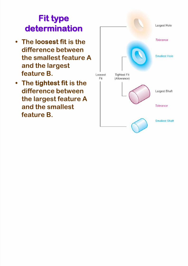
Fit typeit type
determinationetermination
• The loosest fit is the
difference betweenthe smallest feature A
and the largest
feature B.
• The tightest fit is the
difference between
the largest feature A
and the smallest
feature B.
8/3/2019 Geometric Dimension Ing Tolerancing Part2
http://slidepdf.com/reader/full/geometric-dimension-ing-tolerancing-part2 22/36
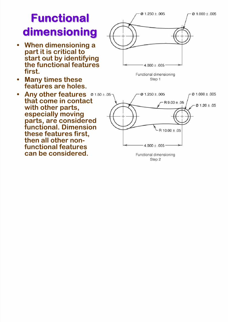
Functionalunctional
dimensioningimensioning• When dimensioning a
part it is critical tostart out by identifyingthe functional features first.
• Many times these features are holes.
• Any other featuresthat come in contact with other parts,especially moving
parts, are considered functional. Dimensionthese features first,then all other non- functional features
can be considered.
8/3/2019 Geometric Dimension Ing Tolerancing Part2
http://slidepdf.com/reader/full/geometric-dimension-ing-tolerancing-part2 23/36
Tolerance Stackolerance Stack-Upp• The additive rule for tolerances is that
tolerances taken in the same direction from one point of reference are
additive
• The corollary is that tolerances to thesame point taken from different
directions becomes additive.
• The effect is called tolerance stack-up
8/3/2019 Geometric Dimension Ing Tolerancing Part2
http://slidepdf.com/reader/full/geometric-dimension-ing-tolerancing-part2 24/36
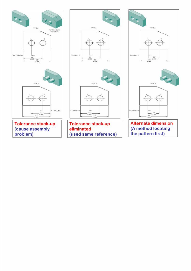
Tolerance stack-up
(cause assemblyproblem)
Tolerance stack-up
eliminated(used same reference)
Alternate dimension
(A method locatingthe pattern first)
8/3/2019 Geometric Dimension Ing Tolerancing Part2
http://slidepdf.com/reader/full/geometric-dimension-ing-tolerancing-part2 25/36
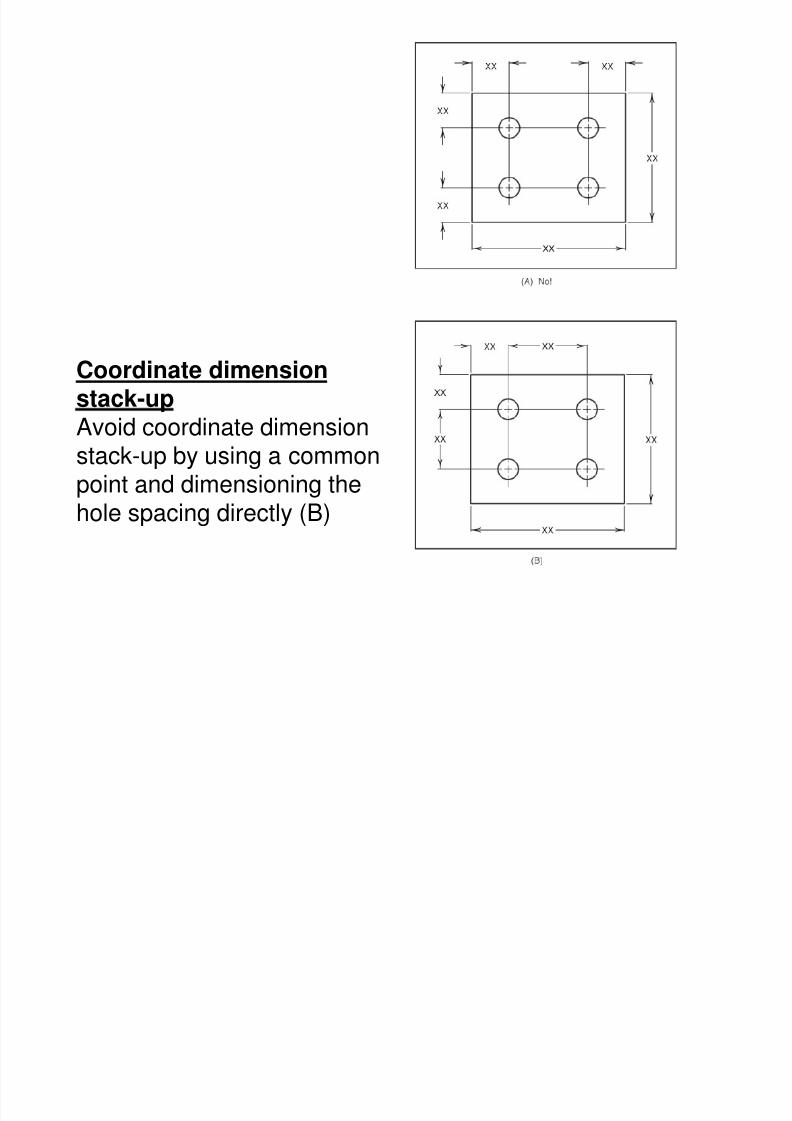
Coordinate dimensionstack-up
Avoid coordinate dimensionstack-up by using a commonpoint and dimensioning thehole spacing directly (B)
8/3/2019 Geometric Dimension Ing Tolerancing Part2
http://slidepdf.com/reader/full/geometric-dimension-ing-tolerancing-part2 26/36
Metric limits and fitsetric limits and fits• The standards used for metric
measurements are recommended bythe ISO and are given in ANSI B4.2-
1978
• The terms used in metric tolerencingare follows:
8/3/2019 Geometric Dimension Ing Tolerancing Part2
http://slidepdf.com/reader/full/geometric-dimension-ing-tolerancing-part2 27/36
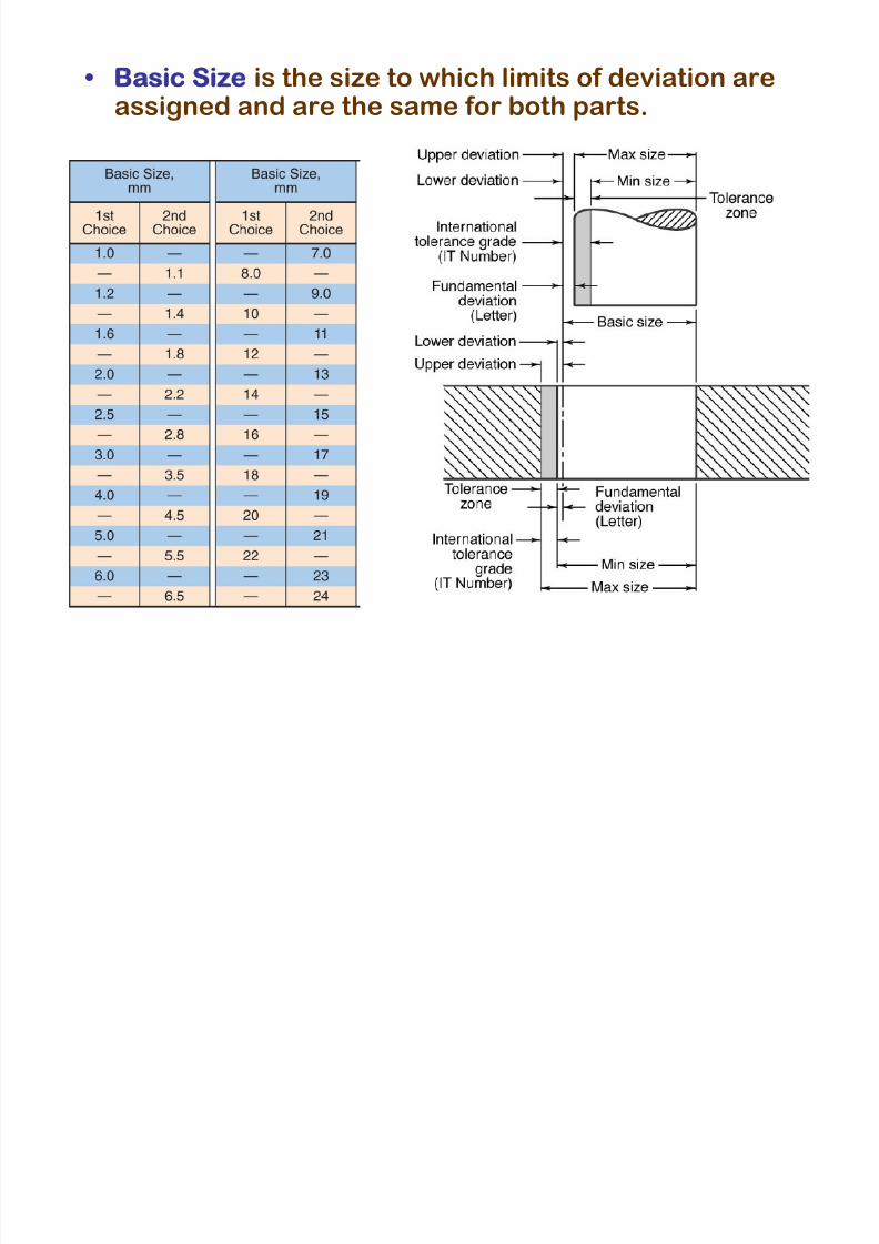
• Basic Size is the size to which limits of deviation areassigned and are the same for both parts.
8/3/2019 Geometric Dimension Ing Tolerancing Part2
http://slidepdf.com/reader/full/geometric-dimension-ing-tolerancing-part2 28/36
8/3/2019 Geometric Dimension Ing Tolerancing Part2
http://slidepdf.com/reader/full/geometric-dimension-ing-tolerancing-part2 29/36
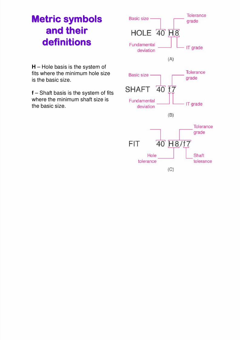
Metric symbolsetric symbols
and theirnd theirdefinitionsefinitions
H – Hole basis is the system offits where the minimum hole size
is the basic size.
f – Shaft basis is the system of fits
where the minimum shaft size isthe basic size.
8/3/2019 Geometric Dimension Ing Tolerancing Part2
http://slidepdf.com/reader/full/geometric-dimension-ing-tolerancing-part2 30/36
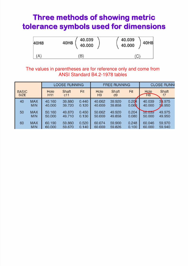
Three methods of showing metrichree methods of showing metric
tolerance symbols used for dimensionsolerance symbols used for dimensions
The values in parentheses are for reference only and come fromANSI Standard B4.2-1978 tables
8/3/2019 Geometric Dimension Ing Tolerancing Part2
http://slidepdf.com/reader/full/geometric-dimension-ing-tolerancing-part2 31/36
Example Determine the Tolerancexample Determine the Tolerance
using The Hole Basis Systemsing The Hole Basis System
• Given:
– A shaft & Hole – The hole basis system
– Clearance fit, and
– A basic diameter of 41mm for the hole
8/3/2019 Geometric Dimension Ing Tolerancing Part2
http://slidepdf.com/reader/full/geometric-dimension-ing-tolerancing-part2 32/36
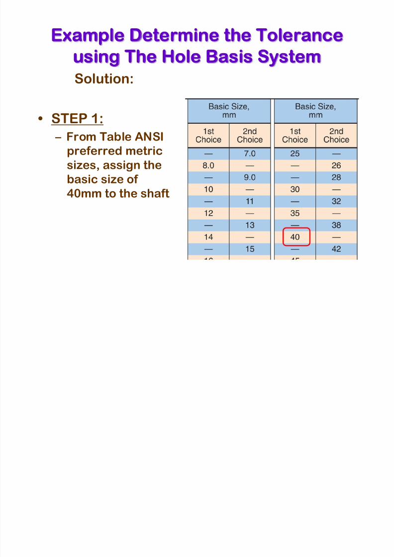
Example Determine the Tolerancexample Determine the Tolerance
using The Hole Basis Systemsing The Hole Basis SystemSolution:
• STEP 1:
– From Table ANSI
preferred metric
sizes, assign thebasic size of
40mm to the shaft
8/3/2019 Geometric Dimension Ing Tolerancing Part2
http://slidepdf.com/reader/full/geometric-dimension-ing-tolerancing-part2 33/36
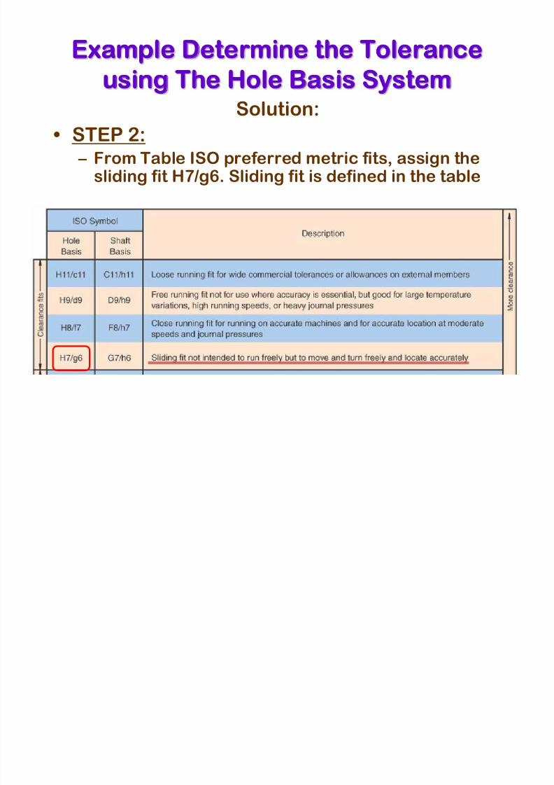
Example Determine the Tolerancexample Determine the Tolerance
using The Hole Basis Systemsing The Hole Basis SystemSolution:
• STEP 2:
– From Table ISO preferred metric fits, assign thesliding fit H7/g6. Sliding fit is defined in the table
8/3/2019 Geometric Dimension Ing Tolerancing Part2
http://slidepdf.com/reader/full/geometric-dimension-ing-tolerancing-part2 34/36
Example Determine the Tolerancexample Determine the Tolerance
using The Hole Basis Systemsing The Hole Basis System
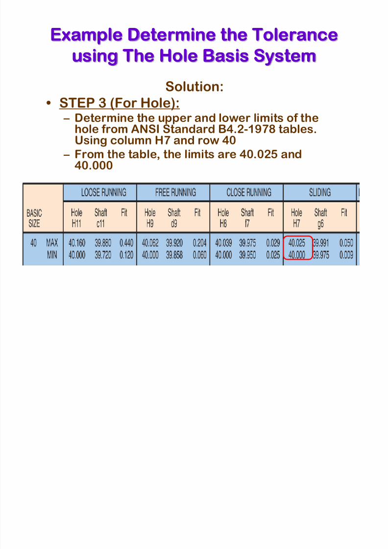
Solution:
• STEP 3 (For Hole): – Determine the upper and lower limits of thehole from ANSI Standard B4.2-1978 tables.Using column H7 and row 40
– From the table, the limits are 40.025 and40.000
8/3/2019 Geometric Dimension Ing Tolerancing Part2
http://slidepdf.com/reader/full/geometric-dimension-ing-tolerancing-part2 35/36
Example Determine the Tolerancexample Determine the Tolerance
using The Hole Basis Systemsing The Hole Basis System
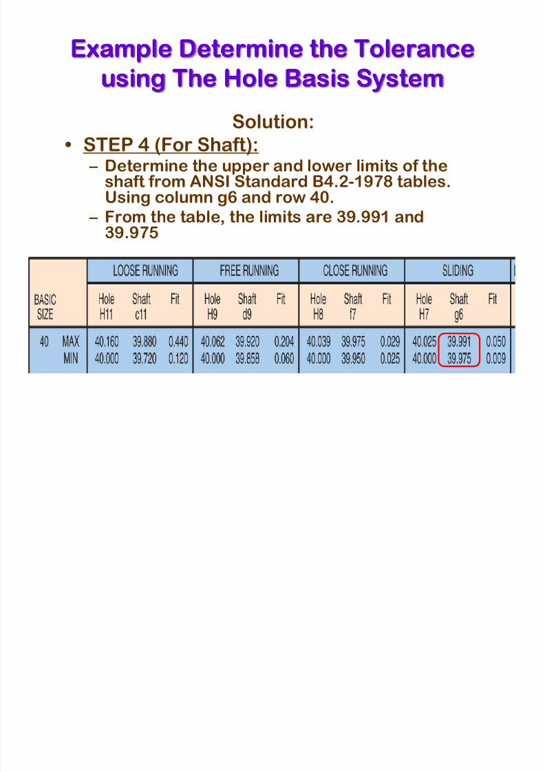
Solution:
• STEP 4 (For Shaft): – Determine the upper and lower limits of theshaft from ANSI Standard B4.2-1978 tables.Using column g6 and row 40.
– From the table, the limits are 39.991 and39.975

8/3/2019 Geometric Dimension Ing Tolerancing Part2
http://slidepdf.com/reader/full/geometric-dimension-ing-tolerancing-part2 36/36
NEXT continue to GDT 3EXT continue to GDT 3