Embed Size (px)
Citation preview
Copyright of Shell SGSI
Geomechanical aspects of injecting CO2 in an underground depleted gas reservoir
Sietse de VriesShell Global Solutions International
Rijswijk, the Netherlands
9th Euroconference on Rock Physics and Geomechanics17-21 October 2011
Trondheim, Norway
Co-authors:
Joel Ita, Ashok Shinde, Rob van Eijs, Mark Davison, Andreas Bauer
Acknowledgement: Rick Wentinck, Peter Schutjens

Copyright of Shell SGSI
Outline
� Introduction to Goldeneye Project
� CCS project workflows and geomechanics
� How the geomechanical model of Goldeneye was build
� Results from geomechanical modeling of Goldeneye
� Subsidence, tensile and shear failure, fault slip, thermal fracturing
� Technology gaps
� Concluding remarks
2
Copyright of Shell SGSI
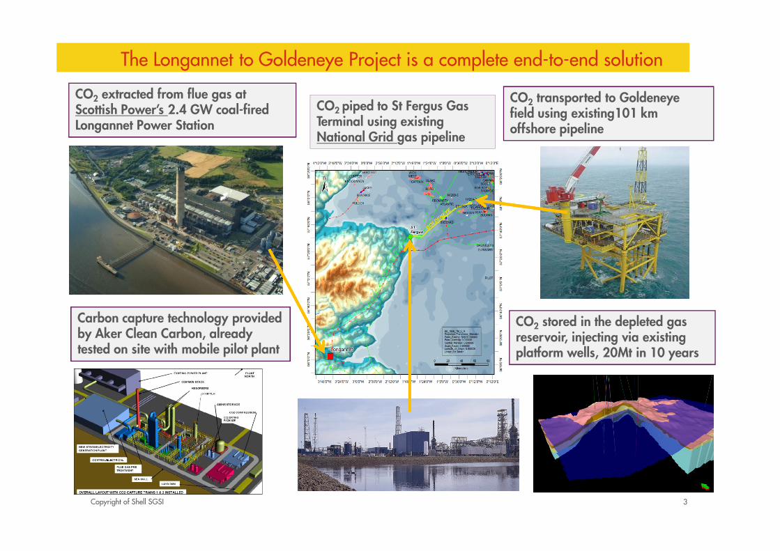
The Longannet to Goldeneye Project is a complete end-to-end solution
3
CO2 piped to St Fergus Gas Terminal using existing National Grid gas pipeline
CO2 stored in the depleted gas reservoir, injecting via existing platform wells, 20Mt in 10 years
Carbon capture technology provided by Aker Clean Carbon, already tested on site with mobile pilot plant
CO2 transported to Goldeneye field using existing101 km offshore pipeline
CO2 extracted from flue gas at Scottish Power’s 2.4 GW coal-fired Longannet Power Station

Copyright of Shell SGSI
Potential routes for loss of containment
1. Fracturing Caprock /
Seals *
2. Spill-point
3. Diffusion through seal
4. Migration along
faults/fractures*
5. Migration along wells (*)
13
2
4
4
5
* Where Geomechanics
has a critical Impact
Schematic drawing, scales are not reality
Copyright of Shell SGSI
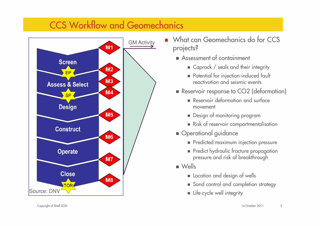
CCS Workflow and Geomechanics
� What can Geomechanics do for CCS projects?� Assessment of containment
� Caprock / seals and their integrity
� Potential for injection-induced fault reactivation and seismic events
� Reservoir response to CO2 (deformation)
� Reservoir deformation and surface movement
� Design of monitoring program
� Risk of reservoir compartmentalisation
� Operational guidance
� Predicted maximum injection pressure
� Predict hydraulic fracture propagation pressure and risk of breakthrough
� Wells
� Location and design of wells
� Sand control and completion strategy
� Life-cycle well integrity
14 October 2011 5
GM Activity
Source: DNV

Copyright of Shell SGSI
What to model and how
� We would like to quantify the risk on tensile or stress failure of the reservoir
and caprock due to the injection of CO2
� Compaction and subsidence
� Fault slip
� Effects of low temperatures close to the well
How is modeling done:
� 3D geomechanical model allows for a Finite Element Modeling that computes
deformation and stress changes due to pressure changes in the reservoir
� Shear Capacity Utilisation (SCU)
6

Copyright of Shell SGSI
Goldeneye CO2 storage container and seals
7
Copyright of Shell SGSI
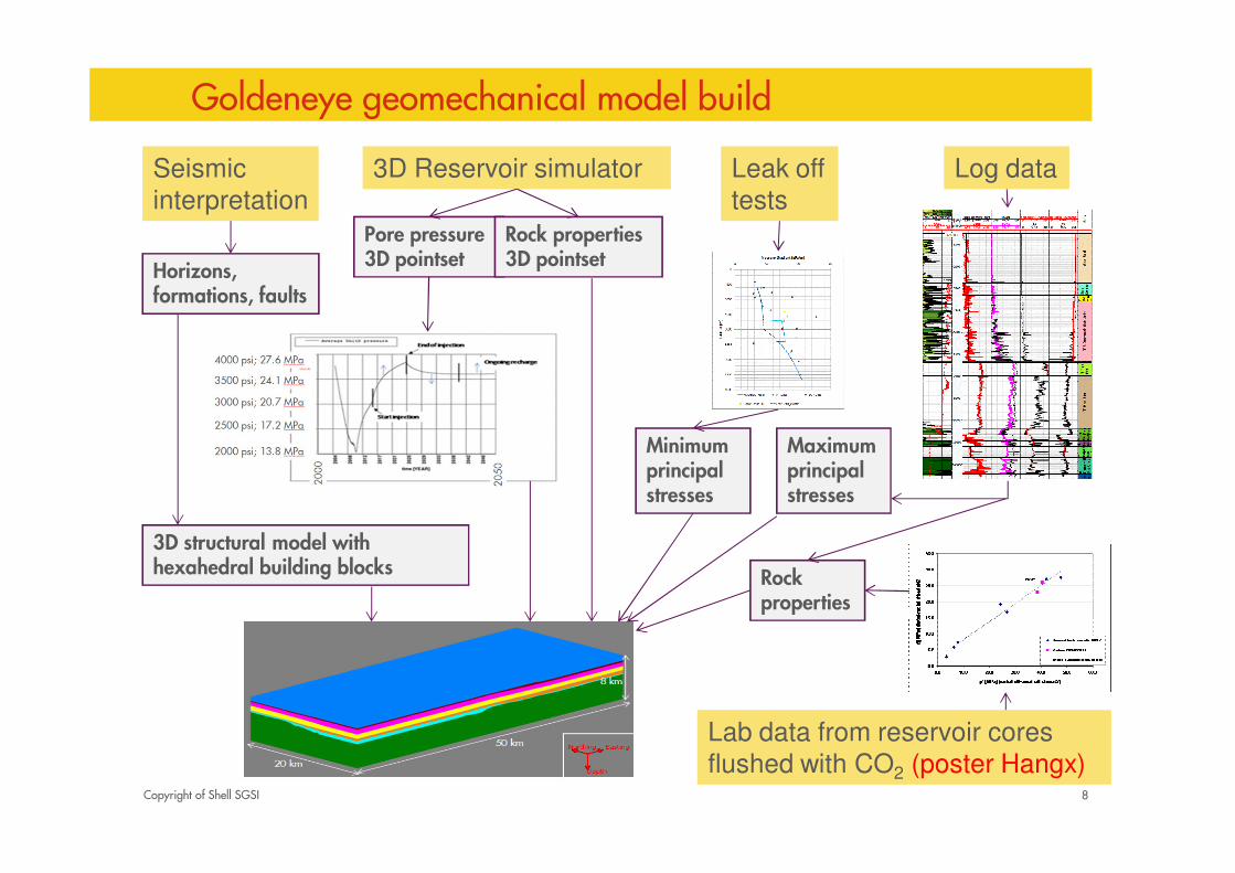
Goldeneye geomechanical model build
8
3D Reservoir simulatorSeismic
interpretation
3D structural model with hexahedral building blocks
Maximum principal stresses
Pore pressure 3D pointset
Rock properties
Horizons, formations, faults
Log dataLeak off
tests
Lab data from reservoir cores
flushed with CO2 (poster Hangx)
Rock properties 3D pointset
Minimum principal stresses

Copyright of Shell SGSI
Reservoir Stress Path
� Injection of CO2 into a previously depleted reservoir
� Issue – The effective in-situ stresses are directly
impacted by the reduction and then the inflation in
reservoir pressure
� Detail - We (industry) have a reasonable
understanding of the depletion scenario in terms of
the coupling between the in-situ stress and pore
pressure, however, there is distinct paucity of data
showing what happens with reservoir pressure
inflation. This is of major importance if we want to
understand whether we are injecting CO2 under
matrix or fracturing conditions, as well as issues
such as fault reactivation and surface deformation
� Risk mitigation: XLOT
9

Copyright of Shell SGSI
Alteration of rock mechanical properties with time
10
� Injected CO2 can react with mineral phases present in reservoir and caprock� Issue – Rock mechanical material properties affected by interaction with CO2 over time� Detail – Chemical disequilibria imposed by introduction of CO2 into reservoir both
dissolves and/or precipitates mineral phases. Geomechanical modelling is required to account for the changes in rock properties with time to gauge the impact these processes have on containment
� Risk Mitigation: � Core tests (poster Hangx)
Modified from Johnson et al, 2004

Copyright of Shell SGSI
Subsidence and compaction modeling results
11
GeoMec model: 360.000 elements, FEM takes 6 hours for 2 depletion stages (after gas has been depleted, and after CO2 has been injected)
Bird’s eye view of the sea-floor with subsidence:
So, injection of the CO2 leads to a heave of the seafloor of about 1 cm (P50 case).
Subsidence Seafloor Top reservoir
After gas depletion 4.6 cm 8.9 cm
After CO2 injection 3.6 cm 5.6 cm
0 m
0.05
Copyright of Shell SGSI
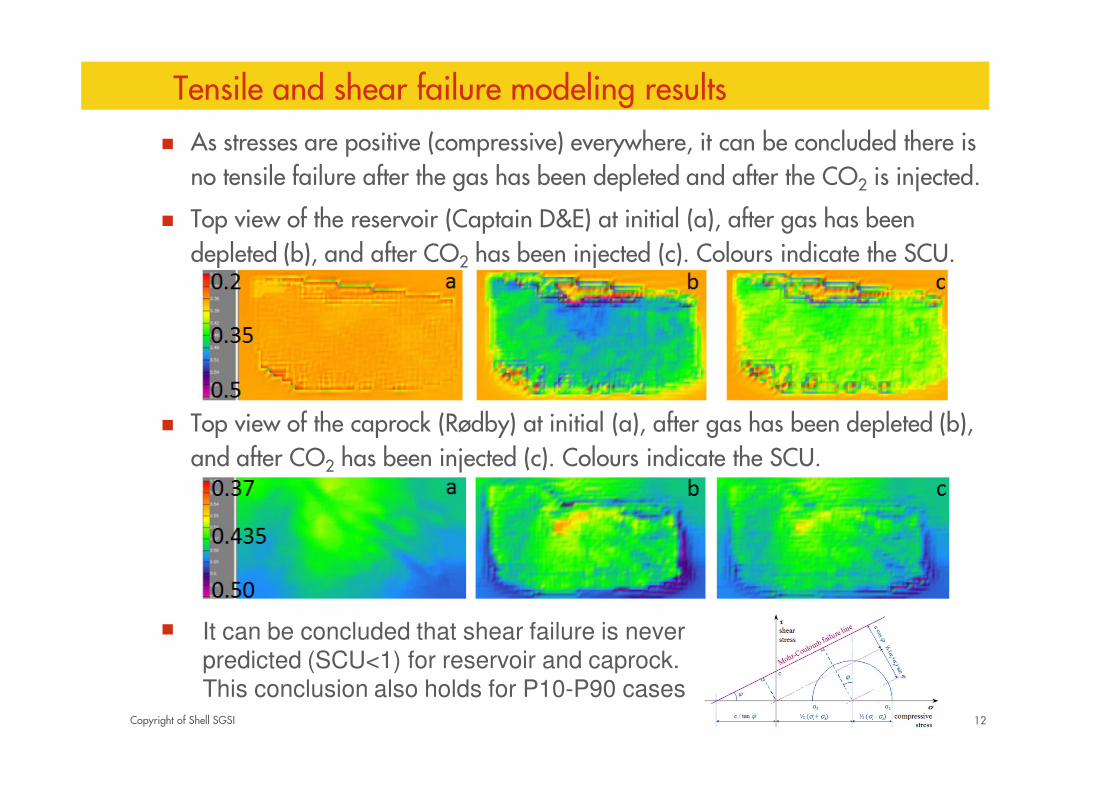
Tensile and shear failure modeling results
� As stresses are positive (compressive) everywhere, it can be concluded there is
no tensile failure after the gas has been depleted and after the CO2 is injected.
� Top view of the reservoir (Captain D&E) at initial (a), after gas has been
depleted (b), and after CO2 has been injected (c). Colours indicate the SCU.
� Top view of the caprock (Rødby) at initial (a), after gas has been depleted (b),
and after CO2 has been injected (c). Colours indicate the SCU.
�
12
It can be concluded that shear failure is never
predicted (SCU<1) for reservoir and caprock.
This conclusion also holds for P10-P90 cases

Copyright of Shell SGSI
Fault slip
� Pressures that change in the reservoir due to gas depletion or CO2 injection can
potentially open fractures and cause slip on faults that exist in the reservoir,
caprock, and overburden formations
� Issue – Some risk analysis of fault reactivation can be carried out using
geomechanical tools, however, there is a distinct lack of data (in industry)
available to show the impact of this
� Detail – We need to be able to predict the risk of leakage associated with fault
reactivation predictions, using geomechanical tools and techniques. The impact
of CO2 and fault zone interaction is potentially significant and will change with
time
13

Copyright of Shell SGSI
� Methodology:
� Stresses from the 3D simulator are mapped on 40 interpreted faults (< P50)
� Calculate the Shear Capacity Utilisation for the two cases where the fault slip properties are equal to the failure parameters of the reservoir or the caprock
� Assumptions:
� Initial stress state of the faults, before depletion or injection, is the same as
the initial stress sate of the surrounding rock
� The faults are not critically stressed
� No fault-slip is expected to occur. Even the worst case scenario (P90) was not
significantly close to slip. This result implies that if faults are currently not
leaking (which they are unlikely to be given that a gas field is present) then
they are extremely unlikely to start leaking as a result of CO2 injection.
Fault slip modeling results
14
Copyright of Shell SGSI
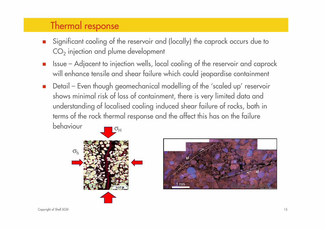
Thermal response
15
� Significant cooling of the reservoir and (locally) the caprock occurs due to
CO2 injection and plume development
� Issue – Adjacent to injection wells, local cooling of the reservoir and caprock
will enhance tensile and shear failure which could jeopardise containment
� Detail – Even though geomechanical modelling of the ‘scaled up’ reservoir
shows minimal risk of loss of containment, there is very limited data and
understanding of localised cooling induced shear failure of rocks, both in
terms of the rock thermal response and the affect this has on the failure
behaviour σH
σh
Cook et al, 2006
Copyright of Shell SGSI
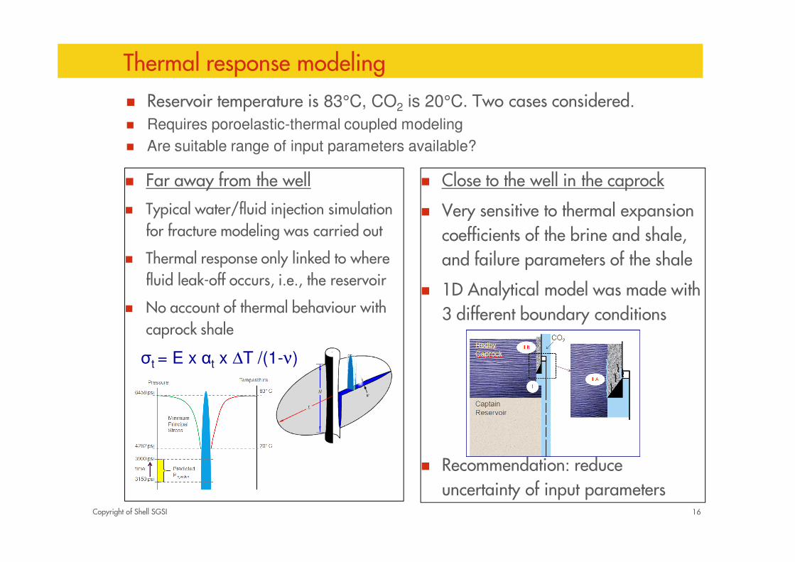
Thermal response modeling
� Far away from the well
� Typical water/fluid injection simulation for fracture modeling was carried out
� Thermal response only linked to where fluid leak-off occurs, i.e., the reservoir
� No account of thermal behaviour with caprock shale
16
� Close to the well in the caprock
� Very sensitive to thermal expansion
coefficients of the brine and shale,
and failure parameters of the shale
� 1D Analytical model was made with
3 different boundary conditions
� Recommendation: reduce
uncertainty of input parameters
� Reservoir temperature is 83°C, CO2 is 20°C. Two cases considered.� Requires poroelastic-thermal coupled modeling
� Are suitable range of input parameters available?
σt = E x αt x ∆T /(1-ν)

Copyright of Shell SGSI
CCS and Geomechanics: Technical Gaps
� Fault Leakage Prediction
� Thermal Response (key technical challenge in the geomechanics modeling in
the Goldeneye Project)
� Reservoir Stress Path
� Alteration of rock mechanical properties with time
� All gaps discussed at the IEAGHG Meeting in Perth AU, April 2011
“Modelling of CO2 Geological Storage and Wellbore Integrity” by Mark Davison, Shell
17

Copyright of Shell SGSI
Concluding Remarks� Geomechanics has a crucial role in trying to understand the containment of a
storage complex
� Also important for: understanding the surface/sub-surface deformation,
providing input to operational guidelines, impacts on well integrity
� A developed workflow was applied to the Goldeneye project to identify
threats and quantify risks before, during, and after injection of CO2 to ensure
containment
� From the 3D geomechanical modeling follows:
� Seafloor subsidence: no risk
� Tensile and shear failure in the reservoir and caprock: no risk
� Fault slip: very unlikely
� Thermal fracturing: ongoing study to reduce uncertainties
18
Copyright of Shell SGSI
Acknowledgement
� UK Department of Energy and Climate Change (DECC) made a substantial
financial contribution to do the studies on the Goldeneye project
� All reports will be available soon via the internet
� Longannet (coal plant) and/or Peterhead (gas plant)?
19