Embed Size (px)
Citation preview
The Southern African Institute of Mining and Metallurgy Slope Stability 2015 I.G. Mendive, A. Abad, and A. Sfriso
1
Geomechanical analysis of open pits at Cerro Vanguardia
I. García Mendive, A. Abad, and A. Sfriso SRK Consulting Argentina
Cerro Vanguardia is a gold-silver mine located in the central steppe of Santa Cruz province, Argentina. The deposit consists of several veins 3.5–10 m in width and 19 km in length. Mining is currently carried out by means of open pits averaging 100–200 m in depth and, more recently, underground developments. More than 50 open pits are expected to be developed during the lifetime of the project. This work presents the stability assessment carried out on pit Osvaldo Diez cutback 7, which comprises limit equilibrium analysis (LEA) and finite element modelling (FEM).
Cerro Vanguardia
Geological model
The Cerro Vanguardia epithermal Au-Ag deposit is situated within the Deseado Massif (De Giusto et al., 1980). It encompasses a 60 000 km area in which Jurassic volcanism is the predominant episode, associated with the rifting originated by the opening of the Atlantic Ocean (Uliana et al., 1985).
Heather, Perez, and Caram (2004) performed the latest geological study of Cerro Vanguardia Project, according to which the deposit consists of 102 epithermal low-sulphidation veins mineralized with Au and Ag, hosted in rhyolitic ignimbrites of Jurassic age. Veins span a length of 193 km, measure 3.5 m in width on average (10 m maximum), and dip 60°–90° NE. Ore consists mainly of silica veinlets, irregular dendritic fissures, stockworks, breccia pipes, vesicular fillings, and dissemination.
Due to the high degree of fracturing and hydrothermal activity, the country rock is pervasively altered. Alteration of felsic rocks such as rhyodacite or rhyolite is characterized by alteration of felsic minerals to sericite, replacement of felsic minerals by silica, and introduction of feldespatides into the system. The most common alteration minerals include carbonates, clay minerals, kaolin, and especially montmorillonite.
Site stratigraphy consists of a repetitive series of felsic ignimbrites divided into stratified, grainy, brecciated (subdivided intro base breccia, breccia, and superior stratified) and massive slabby (composed of 7 sub-units).
Structural model
Within the Cerro Vanguardia anticline, the stratigraphic sequence dips 7° (on average) in direction 146° SE. The rock mass is moderately to intensely fractured, with clear fracture patterns. The main direction at mine scale is 328°/87°. Fractures with densities greater than 5 per metre have a marked principal direction, namely 323°/85°, which correlates them directly to veins and veinlets (dominant orientations are respectively 323°/86° and 323°/89°). Faults determine the general fracturing of the rock mass, with the principal direction 324°/83°.
Intact rock model
In order to simplify stability analyses for a multi-pit mine, Hormazábal et al. (2004) suggested sorting the rock mass into simple categories that grouped similar mechanical properties. These basic geotechnical units were classified according to the degree of alteration into soft argillic, soft, and hard, the latter being subdivided into three subcategories (small blocks, big blocks, massive) in relation to the degree of fracturing of the rock mass. In addition, recent geotechnical reports have included a subdivision of the Soft unit on the basis of fracturing. In the light of new tests, however, the authors have not observed differences in intact rock characteristics that can be ascribed to the block size, except for the Hard Massive unit.
The four intact rock units (IRUs) have been defined on the basis of 68 uniaxial compression tests, 16 tension tests, 121 triaxial tests, 23 Young’s modulus tests, and 239 unit weight tests. Samples were taken from several veins in the footwall, hangingwall, and the orebody itself. Materials encompass grainy, brecciated, and slabby ignimbrite, as well as argillic and siliceous alteration.
Slope Stability 2015
2
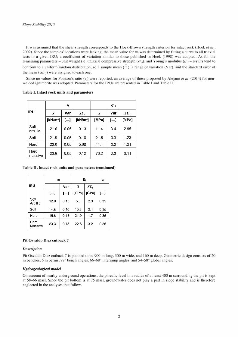
It was assumed that the shear strength corresponds to the Hoek-Brown strength criterion for intact rock (Hoek et al., 2002). Since the samples’ locations were lacking, the mean value for mi was determined by fitting a curve to all triaxial tests in a given IRU; a coefficient of variation similar to those published in Hoek (1998) was adopted. As for the remaining parameters – unit weight ( ), uniaxial compressive strength ( ci), and Young’s modulus (Ei) – results tend to
conform to a uniform random distribution, so a sample mean ( x ), a range of variation (Var), and the standard error of the mean ( SE
x) were assigned to each one.
Since no values for Poisson’s ratio (vi) were reported, an average of those proposed by Alejano et al. (2014) for non-welded ignimbrite was adopted. Parameters for the IRUs are presented in Table I and Table II.
Table I. Intact rock units and parameters
Table II. Intact rock units and parameters (continued)
Pit Osvaldo Diez cutback 7
Description
Pit Osvaldo Diez cutback 7 is planned to be 900 m long, 300 m wide, and 160 m deep. Geometric design consists of 20 m benches, 6 m berms, 78° bench angles, 66–68° interramp angles, and 54–58° global angles.
Hydrogeological model
On account of nearby underground operations, the phreatic level in a radius of at least 400 m surrounding the pit is kept at 58–66 masl. Since the pit bottom is at 75 masl, groundwater does not play a part in slope stability and is therefore neglected in the analyses that follow.

Geomechanical analysis of open pits at Cerro Vanguardia
3
Geotechnical domains
Osvaldo Diez cutback 7 is divided into five geotechnical domains (see Figure 1, left). In Domain 1 the intact rock is generally competent, and has therefore been defined as ‘Hard’. There is, however, an
altered, very fractured 40 m thick band, that has been identified as‘Soft’. The final berm geometry is conditioned by a set of persistent structures that dip into the slope (see Figure 1, right).
Figure 1 – Geotechnical domains at Osvaldo Diez cutback 7 and section for analysis S1 (left). Views of Domain 1 at bench and inter-ramp scales (right)
Domain 2 comprises highly altered rock in the uppermost 20–30 m, underlain by competent rock. According to core
log data, fracturing is medium to low (RQD>50) without any major gouge bands. Fracturing does not correlate with the degree of alteration: RQDs of 80–100 have been recorded for cores having UCS <5MPa (unconfined compressive strength estimated via Schmidt hammer).
Domain 3 comprises two markedly different zones. On the southeast side, conditions are similar to those in Domain 2, albeit with a less favourable structural orientation. The southwest side comprises a band of highly argillically altered rock; the quality of this rock mass, however, improves as it approaches the main vein.
Domain 4 is composed of a south-dipping ‘Soft’ stratum overlying a ‘Hard’ stratum. Structures are moderately altered and have a low fracture frequency. Exceptionally, a 10–12 m thick band of highly altered, very fractured rock has been identified nearly at the bottom of the pit.
Domain 5 consists of very high quality rock, joints with moderate alteration and medium fracturing, without any gouge bands.
Section for analysis
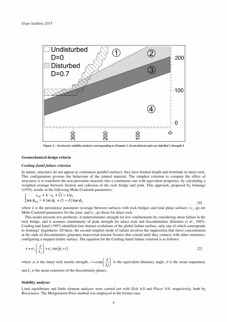
Domain 1 has been selected for stability verifications, on account of the adversely-dipping band of ‘Soft’ rock and its relatively steep global slope angle (55°) (Figure 2). Intact rock units and RMR89 ranges for the geotechnical units were defined on the basis of logs of nearby cores. Good blasting and scaling procedures are applied on site (Adamson et al., 2011), on account of which a factor D=0.7 and a 20 m wide damage zone have been adopted (Hoek, 2012). The undisturbed zone has been assigned D=0.
Slope Stability 2015
4
Figure 2 – Section for stability analysis corresponding to Domain 1. Geotechnical units are labelled 1 through 4
Geomechanical design criteria
Cording-Jamil failure criterion
In nature, structures do not appear as continuous parallel surfaces: they have limited length and terminate in intact rock. This configuration governs the behaviour of the jointed material. The simplest criterion to compute the effect of structures is to transform the non-persistent structure into a continuous one with equivalent properties, by calculating a weighted average between friction and cohesion of the rock bridge and joint. This approach, proposed by Jennings (1970), results in the following Mohr-Coulomb parameters:
[4] where k is the persistence parameter (average between surfaces with rock bridges and total plane surface), (cj, j) are Mohr-Coulomb parameters for the joint, and (cr, r) those for intact rock.
This model presents two problems: it underestimates strength for low confinements by considering shear failure in the rock bridge, and it assumes simultaneity of peak strength for intact rock and discontinuities (Einstein et al., 1983). Cording and Jamil (1997) identified four distinct evolutions of the global failure surface, only one of which corresponds to Jennings’ hypothesis. Of these, the second simplest mode of failure involves the supposition that stress concentration at the ends of discontinuities generates transversal tension fissures that extend until they connect with other structures, configuring a stepped failure surface. The equation for the Cording-Jamil failure criterion is as follows:
= ti
d
Lj
+ n tan j + i( ) [2]
where t is the intact rock tensile strength, i = a tand
Lj is the equivalent dilatancy angle, d is the mean separation,
and Lj is the mean extension of the discontinuity planes.
Stability analyses
Limit equilibrium and finite element analyses were carried out with Slide 6.0 and Phase² 8.0, respectively, both by Rocscience. The Morgenstern-Price method was employed in the former case.
Geomechanical analysis of open pits at Cerro Vanguardia
5
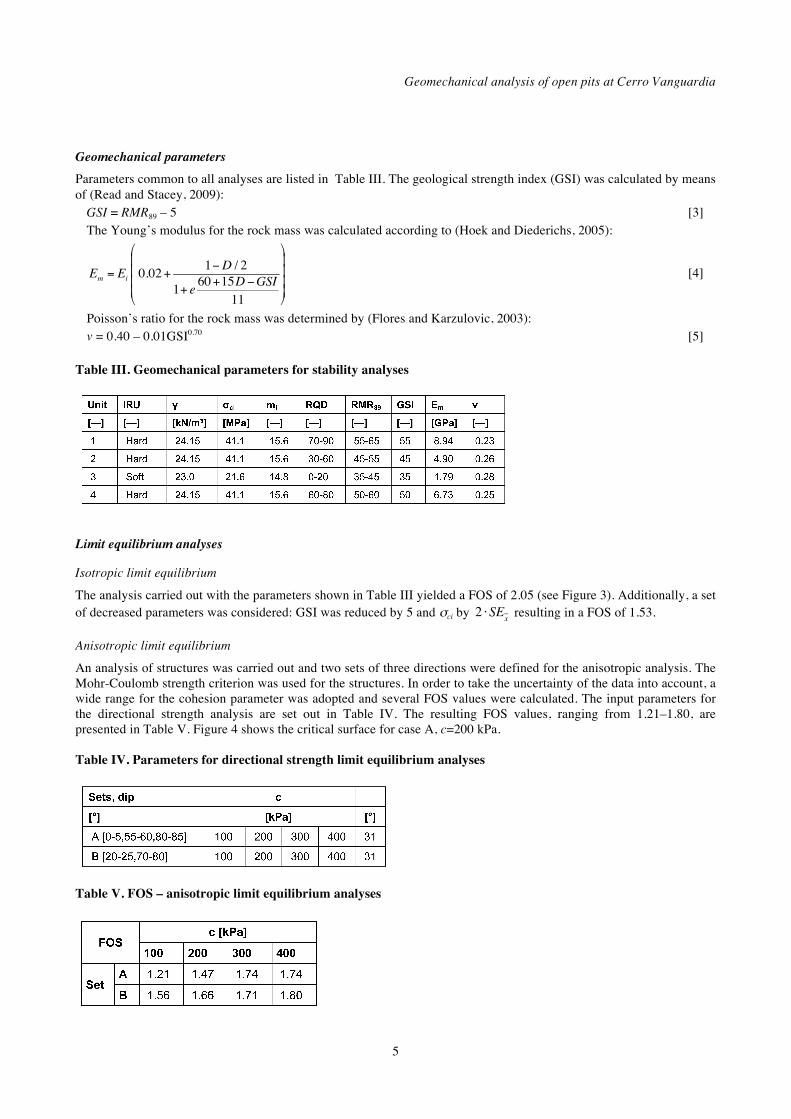
Geomechanical parameters
Parameters common to all analyses are listed in Table III. The geological strength index (GSI) was calculated by means of (Read and Stacey, 2009):
GSI = RMR89 – 5 [3] The Young’s modulus for the rock mass was calculated according to (Hoek and Diederichs, 2005):
Em = Ei 0.02+1 D / 2
1+ e60+15D GSI
11
[4]
Poisson’s ratio for the rock mass was determined by (Flores and Karzulovic, 2003): v = 0.40 – 0.01GSI0.70 [5]
Table III. Geomechanical parameters for stability analyses
Limit equilibrium analyses
Isotropic limit equilibrium
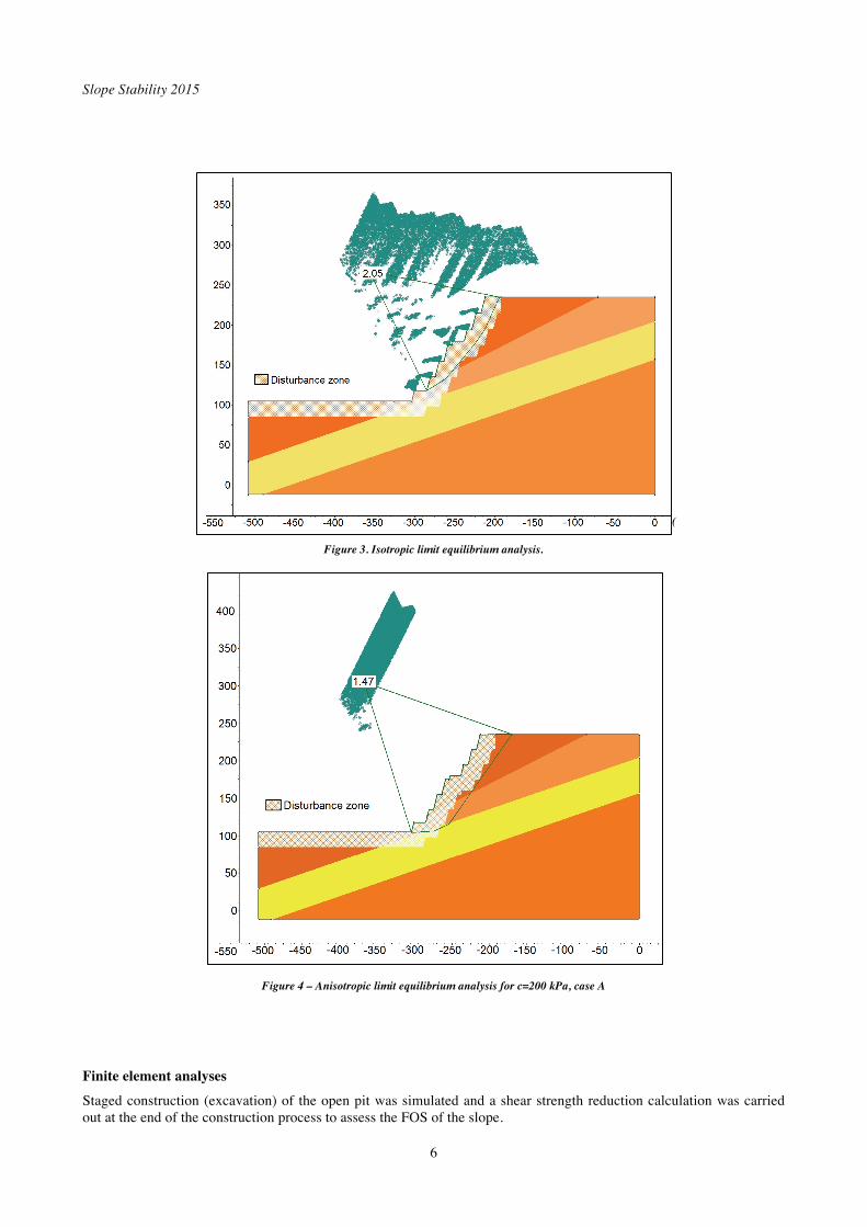
The analysis carried out with the parameters shown in Table III yielded a FOS of 2.05 (see Figure 3). Additionally, a set of decreased parameters was considered: GSI was reduced by 5 and ci by 2 SE
x resulting in a FOS of 1.53.
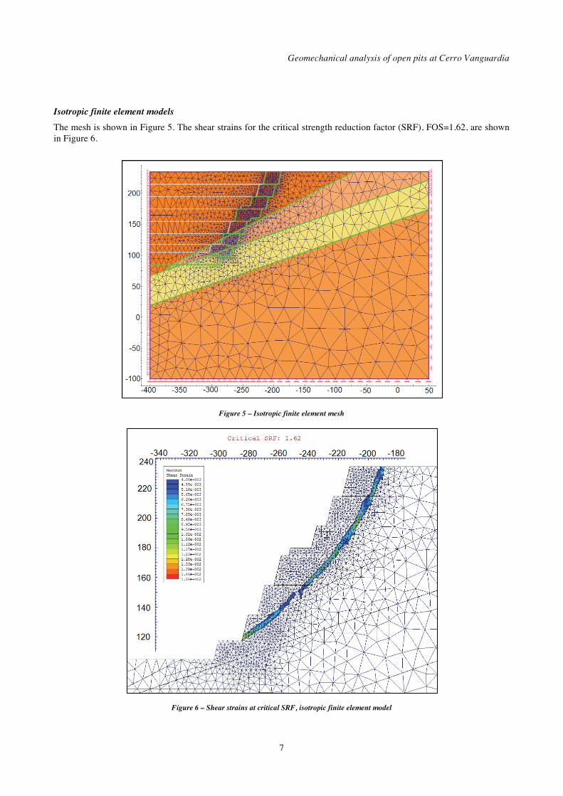
Anisotropic limit equilibrium
An analysis of structures was carried out and two sets of three directions were defined for the anisotropic analysis. The Mohr-Coulomb strength criterion was used for the structures. In order to take the uncertainty of the data into account, a wide range for the cohesion parameter was adopted and several FOS values were calculated. The input parameters for the directional strength analysis are set out in Table IV. The resulting FOS values, ranging from 1.21–1.80, are presented in Table V. Figure 4 shows the critical surface for case A, c=200 kPa. Table IV. Parameters for directional strength limit equilibrium analyses
Table V. FOS – anisotropic limit equilibrium analyses
Slope Stability 2015
6
(
Figure 3. Isotropic limit equilibrium analysis.
Figure 4 – Anisotropic limit equilibrium analysis for c=200 kPa, case A
Finite element analyses
Staged construction (excavation) of the open pit was simulated and a shear strength reduction calculation was carried out at the end of the construction process to assess the FOS of the slope.
Geomechanical analysis of open pits at Cerro Vanguardia
7
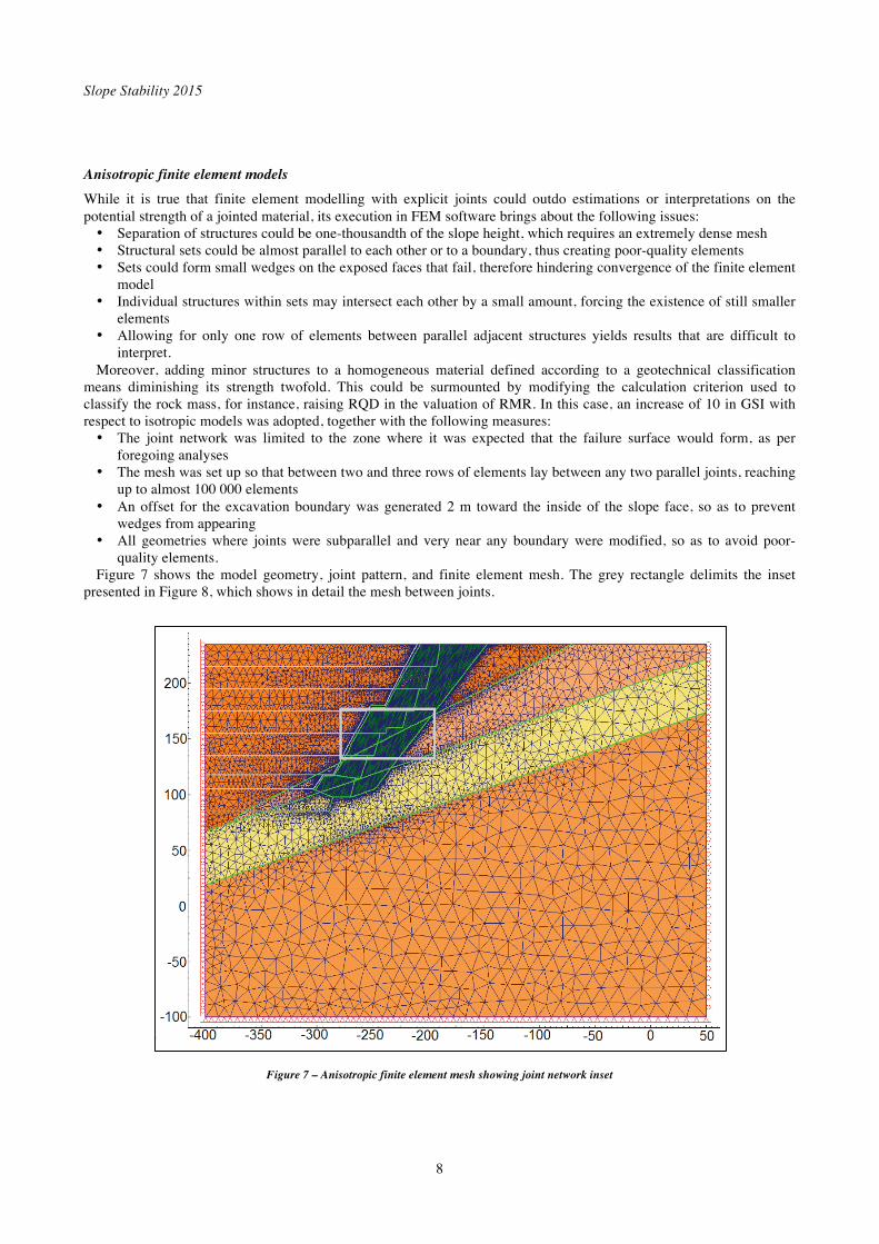
Isotropic finite element models
The mesh is shown in Figure 5. The shear strains for the critical strength reduction factor (SRF), FOS=1.62, are shown in Figure 6.
Figure 5 – Isotropic finite element mesh
Figure 6 – Shear strains at critical SRF, isotropic finite element model
Slope Stability 2015
8
Anisotropic finite element models
While it is true that finite element modelling with explicit joints could outdo estimations or interpretations on the potential strength of a jointed material, its execution in FEM software brings about the following issues: • Separation of structures could be one-thousandth of the slope height, which requires an extremely dense mesh • Structural sets could be almost parallel to each other or to a boundary, thus creating poor-quality elements • Sets could form small wedges on the exposed faces that fail, therefore hindering convergence of the finite element
model • Individual structures within sets may intersect each other by a small amount, forcing the existence of still smaller
elements • Allowing for only one row of elements between parallel adjacent structures yields results that are difficult to
interpret. Moreover, adding minor structures to a homogeneous material defined according to a geotechnical classification
means diminishing its strength twofold. This could be surmounted by modifying the calculation criterion used to classify the rock mass, for instance, raising RQD in the valuation of RMR. In this case, an increase of 10 in GSI with respect to isotropic models was adopted, together with the following measures: • The joint network was limited to the zone where it was expected that the failure surface would form, as per
foregoing analyses • The mesh was set up so that between two and three rows of elements lay between any two parallel joints, reaching
up to almost 100 000 elements • An offset for the excavation boundary was generated 2 m toward the inside of the slope face, so as to prevent
wedges from appearing • All geometries where joints were subparallel and very near any boundary were modified, so as to avoid poor-
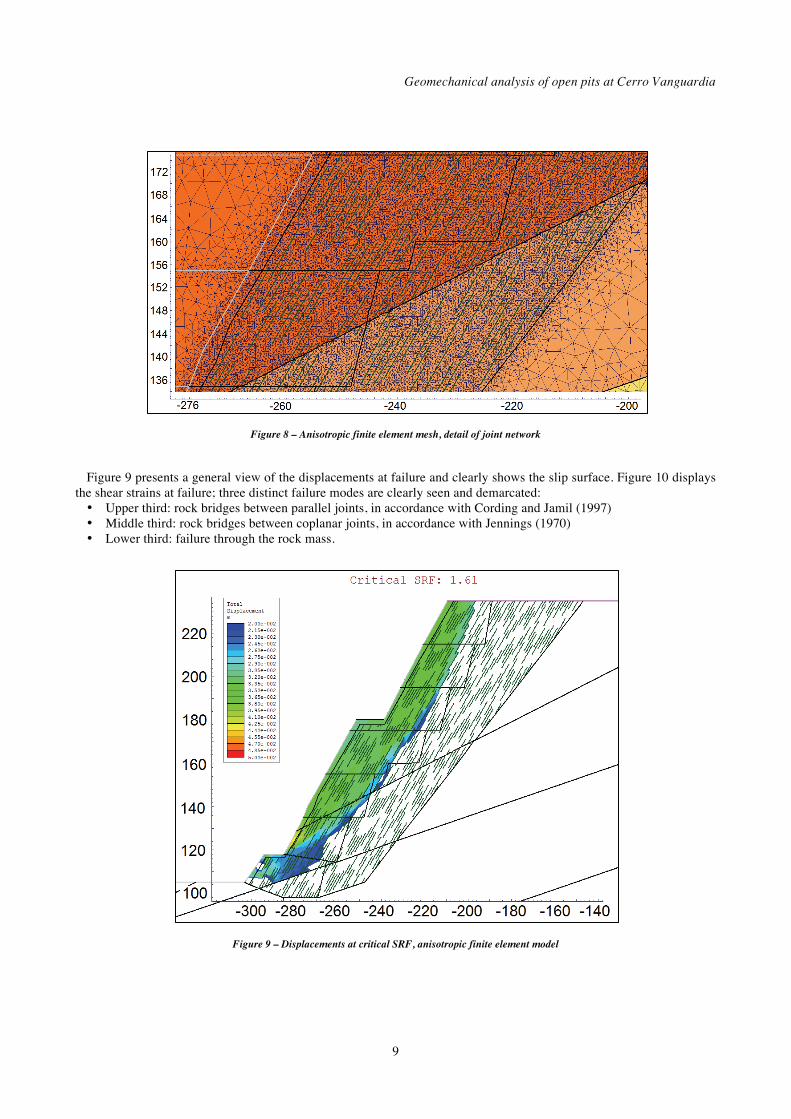
quality elements. Figure 7 shows the model geometry, joint pattern, and finite element mesh. The grey rectangle delimits the inset
presented in Figure 8, which shows in detail the mesh between joints.
Figure 7 – Anisotropic finite element mesh showing joint network inset
Geomechanical analysis of open pits at Cerro Vanguardia
9
Figure 8 – Anisotropic finite element mesh, detail of joint network
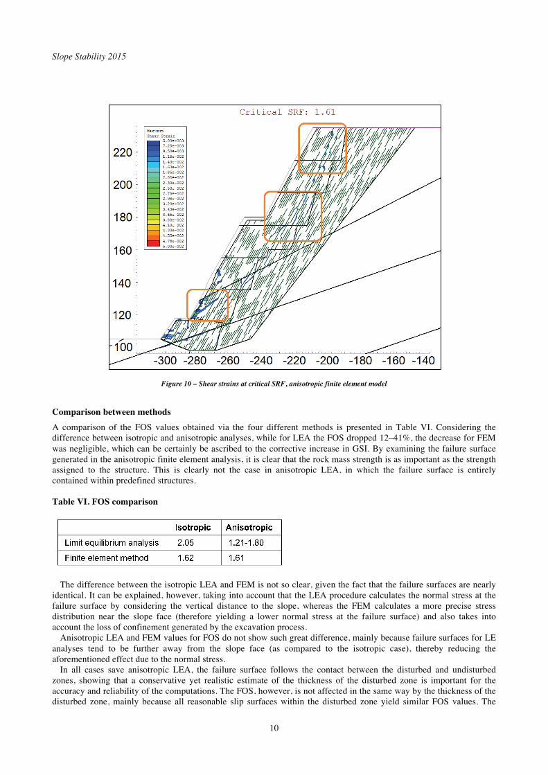
Figure 9 presents a general view of the displacements at failure and clearly shows the slip surface. Figure 10 displays
the shear strains at failure; three distinct failure modes are clearly seen and demarcated: • Upper third: rock bridges between parallel joints, in accordance with Cording and Jamil (1997) • Middle third: rock bridges between coplanar joints, in accordance with Jennings (1970) • Lower third: failure through the rock mass.
Figure 9 – Displacements at critical SRF, anisotropic finite element model
Slope Stability 2015
10
Figure 10 – Shear strains at critical SRF, anisotropic finite element model
Comparison between methods
A comparison of the FOS values obtained via the four different methods is presented in Table VI. Considering the difference between isotropic and anisotropic analyses, while for LEA the FOS dropped 12–41%, the decrease for FEM was negligible, which can be certainly be ascribed to the corrective increase in GSI. By examining the failure surface generated in the anisotropic finite element analysis, it is clear that the rock mass strength is as important as the strength assigned to the structure. This is clearly not the case in anisotropic LEA, in which the failure surface is entirely contained within predefined structures. Table VI. FOS comparison
The difference between the isotropic LEA and FEM is not so clear, given the fact that the failure surfaces are nearly identical. It can be explained, however, taking into account that the LEA procedure calculates the normal stress at the failure surface by considering the vertical distance to the slope, whereas the FEM calculates a more precise stress distribution near the slope face (therefore yielding a lower normal stress at the failure surface) and also takes into account the loss of confinement generated by the excavation process.
Anisotropic LEA and FEM values for FOS do not show such great difference, mainly because failure surfaces for LE analyses tend to be further away from the slope face (as compared to the isotropic case), thereby reducing the aforementioned effect due to the normal stress.
In all cases save anisotropic LEA, the failure surface follows the contact between the disturbed and undisturbed zones, showing that a conservative yet realistic estimate of the thickness of the disturbed zone is important for the accuracy and reliability of the computations. The FOS, however, is not affected in the same way by the thickness of the disturbed zone, mainly because all reasonable slip surfaces within the disturbed zone yield similar FOS values. The
Geomechanical analysis of open pits at Cerro Vanguardia
11
disturbance factor D, on the other hand, does have a large impact on the rock mass strength envelope and is therefore a key parameter in the analysis.
Conclusions
This work presented a geomechanical analysis of the open pit Osvaldo Diez cutback 7 at Cerro Vanguardia mine, Santa Cruz Province, Argentina. The geological, structural, and rock mass model of the mine were outlined, which form the basis for the stability assessment together with the definition of the geotechnical domains for the pit.
The global stability of a particular cross-section was analysed by means of two-dimensional limit equilibrium and finite element analyses, both isotropic and anisotropic. For the limit equilibrium, anisotropy was taken into account by defining a directional strength for the rock mass, assigning parameters to the structures in accordance with the Mohr-Coulomb failure criterion.
For the finite element model, the anisotropy was incorporated by means of explicit joints. The factors of safety obtained were compared based on the underlying assumptions of each method. This enabled the reproduction of the fracture mechanisms which are expected to occur inside the rock mass. The method, powered by the ever-increasing computing capacity available, allows modelling of anisotropic rock masses without the need to resort to analytical criteria or impose directional properties that are difficult to define on a case-to-case basis.
Acknowledgements
The authors gratefully acknowledge the participation of Cerro Vanguardia SA, as well as the permission to publish and present this work.
References
Adamson, W.R., Muñoz, V., and Sarapura, G. 2011. Application of technology for final wall damage control at Cerro Vanguardia, Argentina. Explo 2011: Blasting – Controlled Productivity Melbourne, 8–9 November 2011. Australasian Institute of Mining and Metallurgy, Melbourne. pp. 15–26.
Cording, E. and Jamil, M. 1997. Slide geometrics on rock slopes and walls. Fourth South American Congress on Rock Mechanics. Santiago. Vol 3, pp. 199-221.
De Giusto, J.M., Di Persia, C.A., and Pezzi, E. 1980. Nesocratón del Deseado. Geología Regional Argentina. Turner, J.C.M. (ed.). Academia Nacional de Ciencias, Córdoba. vol. 2, pp. 1389-1430.
Einstein, H.H., Veneziano, D., Baecher, G., and O'Reilly, K.J. 1983. The effect of discontinuity persistence on rock slope stability. International Journal of Rock Mechanics and Mining Sciences and Geomechanics Abstracts, vol. 20, no. 5. pp. 227-236.
Flores, G. and Karzulovic, A. 2003. Geotechnical guideline for a transition from open pit to underground mining: geotechnical characterization. Report to International Caving Study II. JKMRC, Brisbane.
Hoek, E. 2012. Blast Damage Factor D. Technical note for RocNews. 2 February.
Hoek, E. and Diederichs, M.S. 2006. Empirical estimation of rock mass modulus. International Journal of Rock Mechanics and Mining Sciences, vol. 43. pp. 203–215.
Jennings, J E. 1970. A mathematical theory for the calculation of the stability of open cast mines. Proceedings of the Symposium on the Theoretical Background to the Planning of Open Pit Mines, Johannesburg..pp. 87-102.
Lesta, P, and Ferello, R. 1972. Región Extraandina de Chubut y norte de Santa Cruz. Geología Regional Argentina. Leanza, A.F. (ed.). Academia Nacional de Ciencias, Córdoba. pp. 601-653.
Pankhurst, R.J., Caminos, R., and Rapela, C.W. 1993. Problemas geocronológicos de los granitoides gondwánicos de Nahuel Niyeu, Macizo Norpatagónico. XII Congreso Geológico Argentino y II Congreso de Exploración de Hidrocarburos. Vol. IV, pp. 99-104.
Schalamuk, I.B., de Barrio, R.E., Zubia, M., Genini, A., and Echeveste, H. 1999. Provincia auroargentífera del Deseado, Santa Cruz. Recursos Minerales de la República Argentina. Zappettini, E. (ed.). Instituto de Geología y Recursos Minerales, SEGEMAR, Buenos Aires. Anales, vol. 35, no. 2. pp. 1177-1188.

Slope Stability 2015
12
Tessone, M. and Del Blanco, M. 1998. Mineralización epitermal en domos riolíticos de la Formación Chon Aike, Sector Central del Macizo del Deseado, Santa Cruz, Argentina. 10° Congreso Latinoamericano de Geología y 6° Congreso Nacional de Geología Económica, Buenos Aires. Vol. 3. pp. 94-99.
Uliana, M., Biddle, K., Phelps, D., and Gust, D. 1985. Significado del vulcanismo y extensión mesojurásicos en el extremo meridional de Sudamérica. Revista de la Asociación Geológica Argentina, vol. 40. pp. 231-253.
The Author
García Mendive, Iñaki, SRK Consulting, Argentina Iñaki García Mendive has three and a half years of experience in design of geotechnical, geomechanical and hydraulic projects including sheet pile walls, foundations, anchor systems, embankments, slopes, excavations in rock and soil, open pits, underground works, ground filtration and drainage systems. He has provided open pit slope and underground assessment services mines such as Barrick’s Veladero and Anglo Gold Ashanti’s Cerro Vanguardia, in Argentina, and Orosur Mining’s Arenal Deeps, in Uruguay. He provides on-site assistance in design implementation.