Embed Size (px)
Citation preview
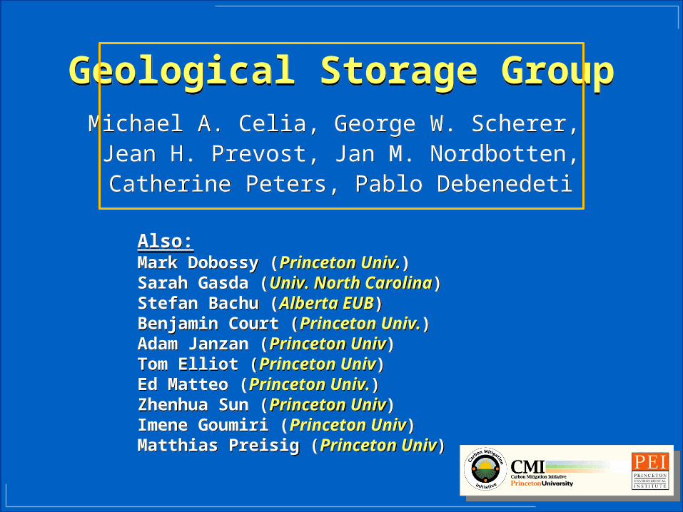
Geological Storage GroupGeological Storage GroupMichael A. Celia, George W. Scherer, Jean H. Prevost, Jan M. Nordbotten,Catherine Peters, Pablo Debenedeti
Michael A. Celia, George W. Scherer, Jean H. Prevost, Jan M. Nordbotten,Catherine Peters, Pablo Debenedeti
Also:Mark Dobossy (Princeton Univ.)Sarah Gasda (Univ. North Carolina)Stefan Bachu (Alberta EUB)Benjamin Court (Princeton Univ.)Adam Janzan (Princeton Univ)Tom Elliot (Princeton Univ)Ed Matteo (Princeton Univ.)Zhenhua Sun (Princeton Univ)Imene Goumiri (Princeton Univ)Matthias Preisig (Princeton Univ)
Also:Mark Dobossy (Princeton Univ.)Sarah Gasda (Univ. North Carolina)Stefan Bachu (Alberta EUB)Benjamin Court (Princeton Univ.)Adam Janzan (Princeton Univ)Tom Elliot (Princeton Univ)Ed Matteo (Princeton Univ.)Zhenhua Sun (Princeton Univ)Imene Goumiri (Princeton Univ)Matthias Preisig (Princeton Univ)
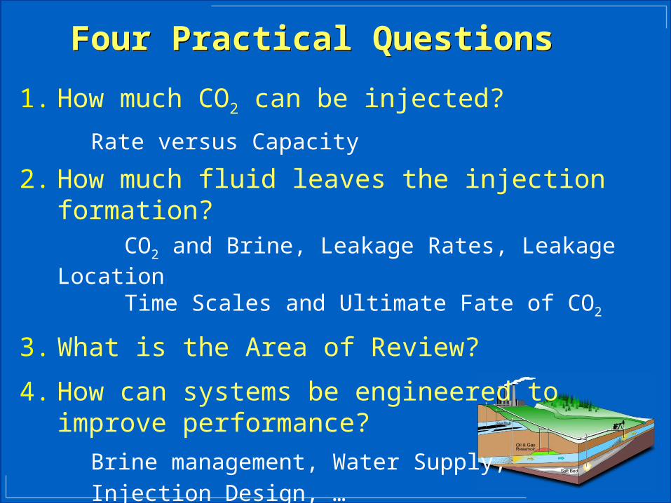
Four Practical QuestionsFour Practical Questions
1. How much CO2 can be injected?
Rate versus Capacity
2. How much fluid leaves the injection formation?CO2 and Brine, Leakage Rates, Leakage LocationTime Scales and Ultimate Fate of CO2
3. What is the Area of Review?
4. How can systems be engineered to improve performance?
Brine management, Water Supply,
Injection Design, …
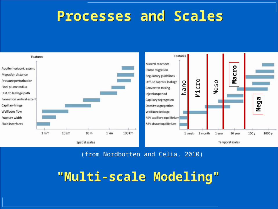
Processes and ScalesProcesses and Scales
"Multi-scale Modeling""Multi-scale Modeling"N
ano
Mic
ro
Meso M
acro
Meg
a
(from Nordbotten and Celia, 2010)
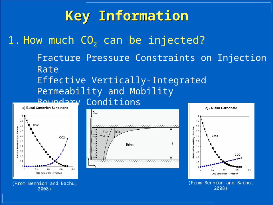
Key InformationKey Information
1. How much CO2 can be injected?
Fracture Pressure Constraints on Injection RateEffective Vertically-Integrated Permeability and Mobility Boundary Conditions
(From Bennion and Bachu, 2008)
(From Bennion and Bachu, 2008)
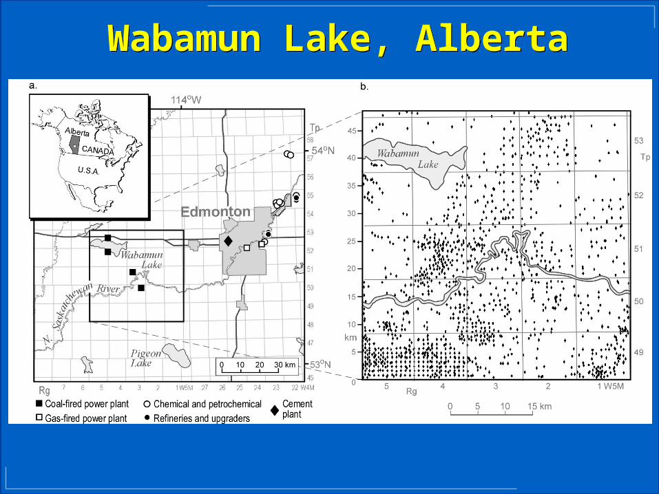
Wabamun Lake, AlbertaWabamun Lake, Alberta

Wabamun Lake, AlbertaWabamun Lake, Alberta

Layer PropertiesLayer Properties
Aquifer Name Depth [m]
Thickness [m]
Permeability [mD]
# Wells
Max Inj Rate
[Mt/year]
Wells reached by CO2 plume
Belly River 729 56 86 1237 2.8 197
Cardium 1052 15 7 1155 0.1 23
Viking 1288 30 53 900 1.7 200
Mannville 1462 65 7 895 1.0 43
Nordegg/Banff 1538 80 4 733 0.7 13
Wabamun 1629 160 4 138 1.1 1
Nisku 1882 72 170 39 21.4 31
Keg River 2507 22 3.5 11 0.2 0
Pika 2845 14 16 2 0.6 0
Basal Sandstone
2965 38 23 1 2.6 1
Key InformationKey Information
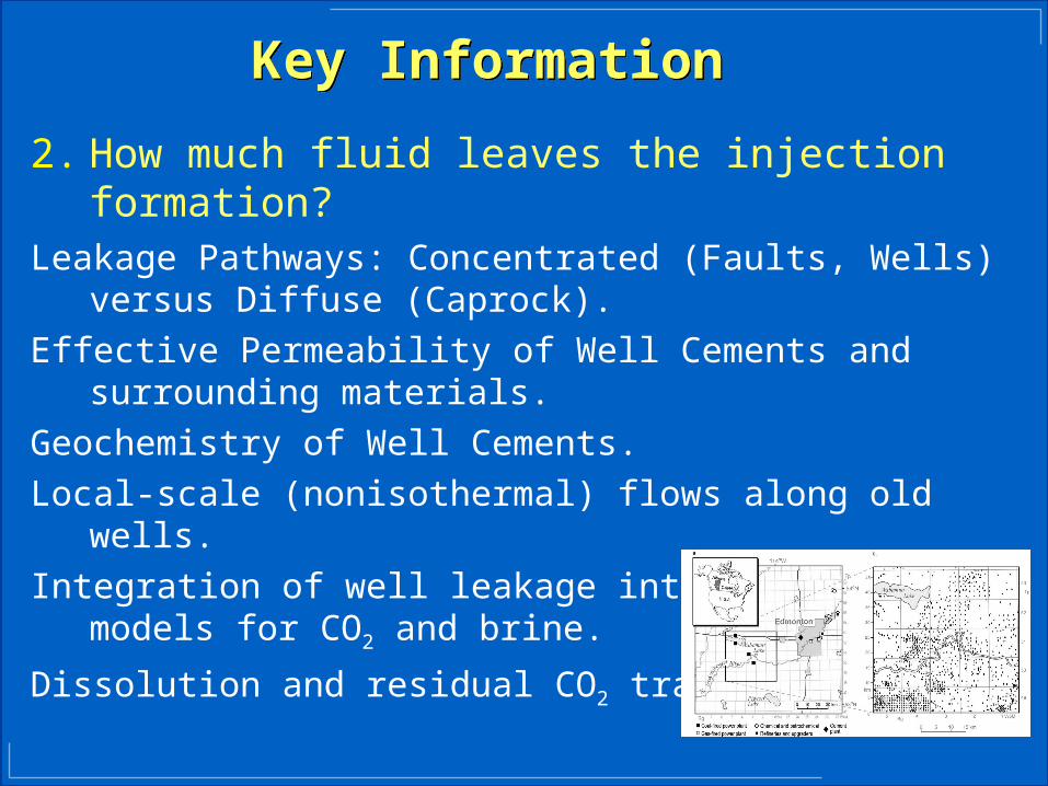
2. How much fluid leaves the injection formation?Leakage Pathways: Concentrated (Faults, Wells) versus Diffuse
(Caprock).
Effective Permeability of Well Cements and surrounding materials.
Geochemistry of Well Cements.
Local-scale (nonisothermal) flows along old wells.
Integration of well leakage into large-scale models for CO2 and brine.
Dissolution and residual CO2 trapping.
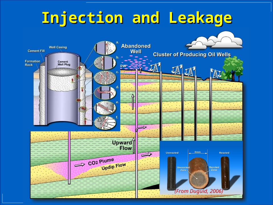
Injection and LeakageInjection and Leakage
(From Duguid, 2006)
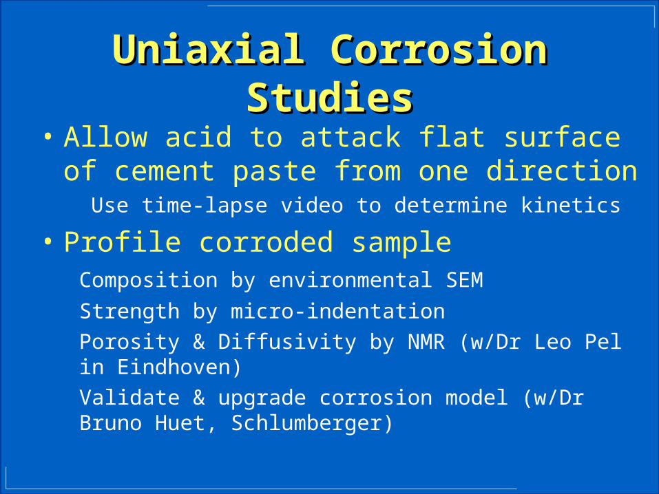
Uniaxial Corrosion StudiesUniaxial Corrosion Studies
• Allow acid to attack flat surface of cement paste from one direction
Use time-lapse video to determine kinetics
• Profile corroded sampleComposition by environmental SEM
Strength by micro-indentation
Porosity & Diffusivity by NMR (w/Dr Leo Pel in Eindhoven)
Validate & upgrade corrosion model (w/Dr Bruno Huet, Schlumberger)

Uniaxial Corrosion KineticsUniaxial Corrosion Kinetics
• Cement in tube is corroded by acid on surfaceTime-lapse movie made using USB microscope
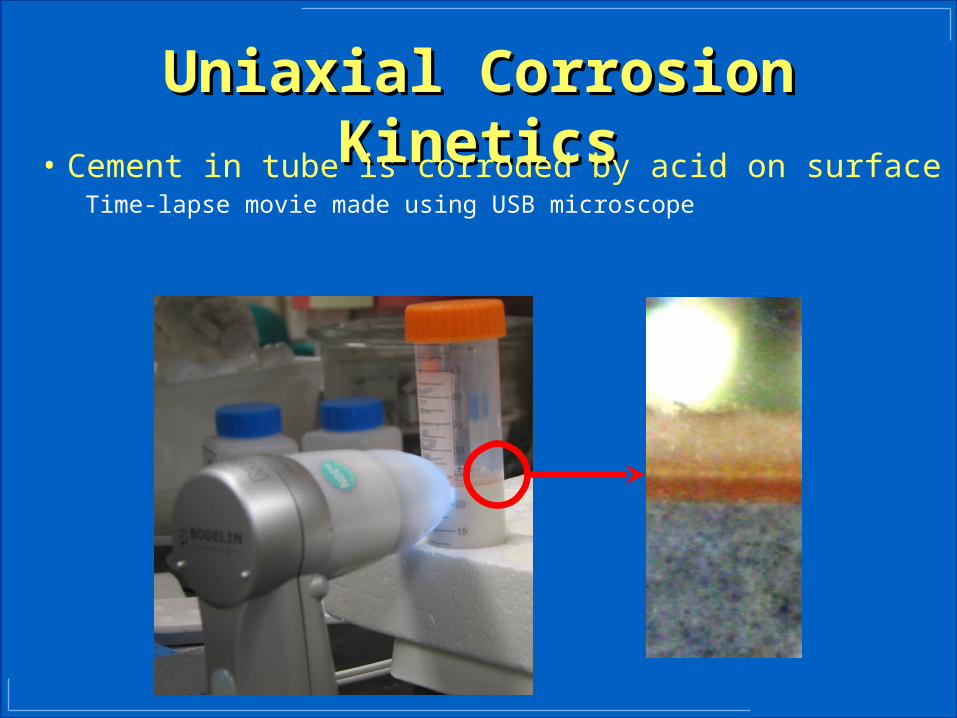
Uniaxial Corrosion KineticsUniaxial Corrosion Kinetics
• Cement in tube is corroded by acid on surfaceTime-lapse movie made using USB microscope
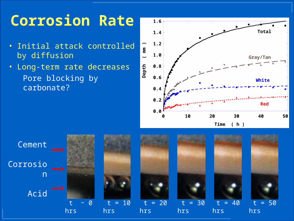
Corrosion Rate
• Initial attack controlled by diffusion
• Long-term rate decreases
Pore blocking by carbonate?
t = 10 hrs
t = 20 hrs
t = 30 hrs
t = 40 hrs
t = 50 hrs
t ~ 0 hrs
Cement
Corrosion
Acid
0.0
0.2
0.4
0.6
0.8
1.0
1.2
1.4
1.6
0 10 20 30 40 50
Dep
th
( m
m )
Time ( h )
Total
Gray/Tan
White
Red
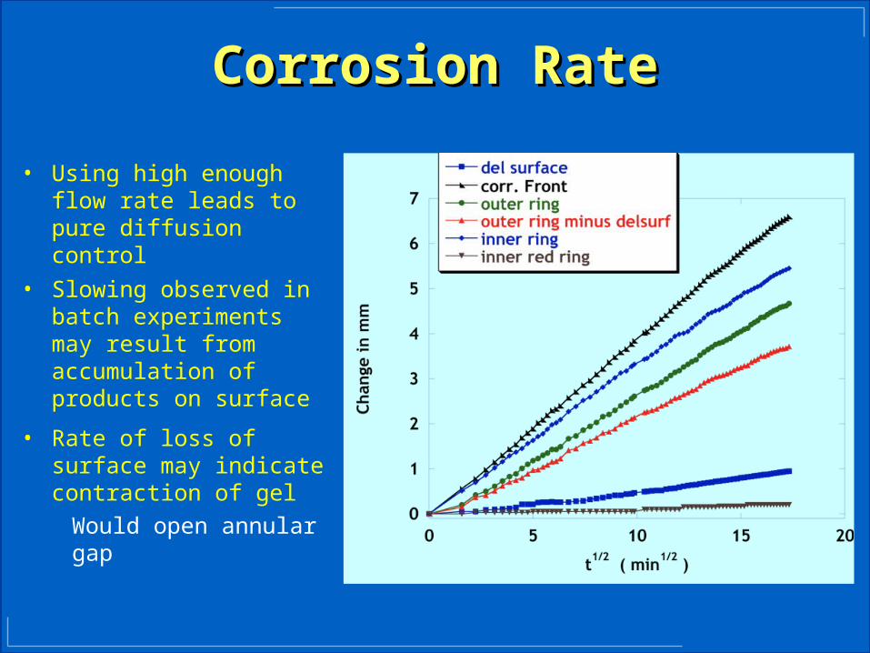
Corrosion RateCorrosion Rate
• Using high enough flow rate leads to pure diffusion control
• Slowing observed in batch experiments may result from accumulation of products on surface
• Rate of loss of surface may indicate contraction of gel
Would open annular gap
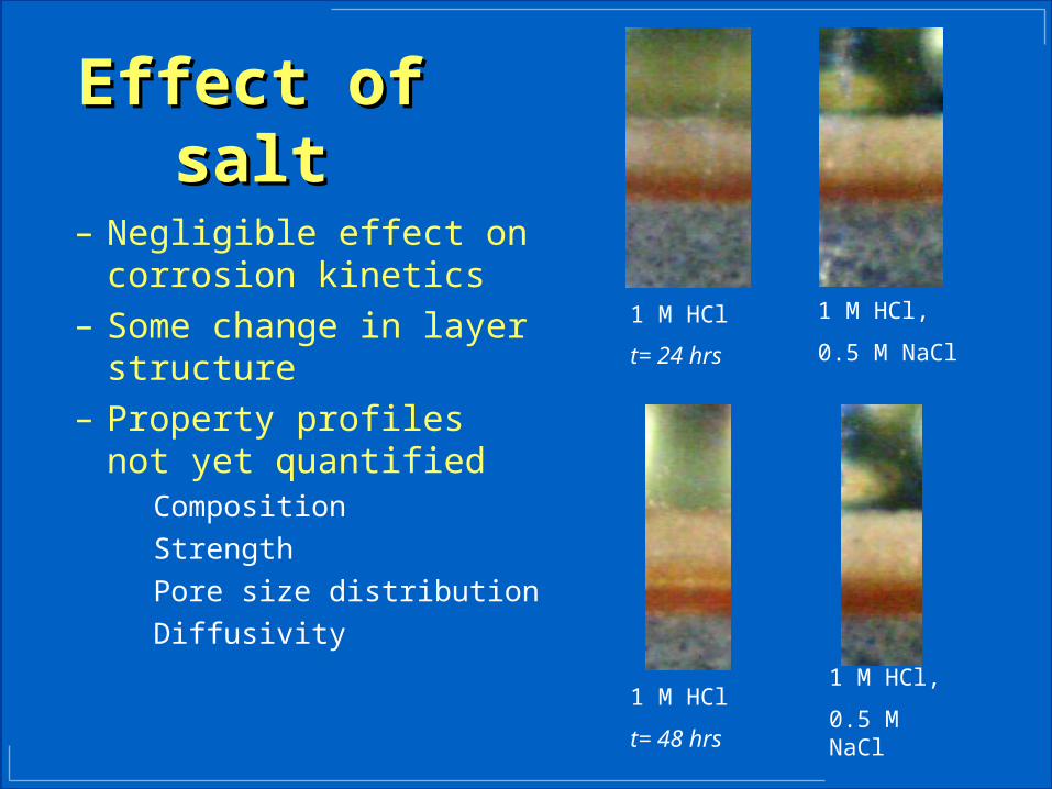
1 M HCl
t= 24 hrs
1 M HCl,
0.5 M NaCl
1 M HCl
t= 48 hrs
1 M HCl,
0.5 M NaCl
Effect of saltEffect of salt
– Negligible effect on corrosion kinetics
– Some change in layer structure
– Property profiles not yet quantified
Composition
Strength
Pore size distribution
Diffusivity

• Simulator created by Jean-Hervé Prévost– Fluid transport fully coupled with geomechanics
(poromechanics)– Reactive transport capabilities for cement
attack/degradation by CO2
– Equation of state - based flash– Heat transfer
• Unique capability to predict phase changes (e.g. boiling of CO2)– Essential for modeling of leakage as carbonated brine
rises in crack
DynaflowDynaflow Fully coupled simulator Fully coupled simulator
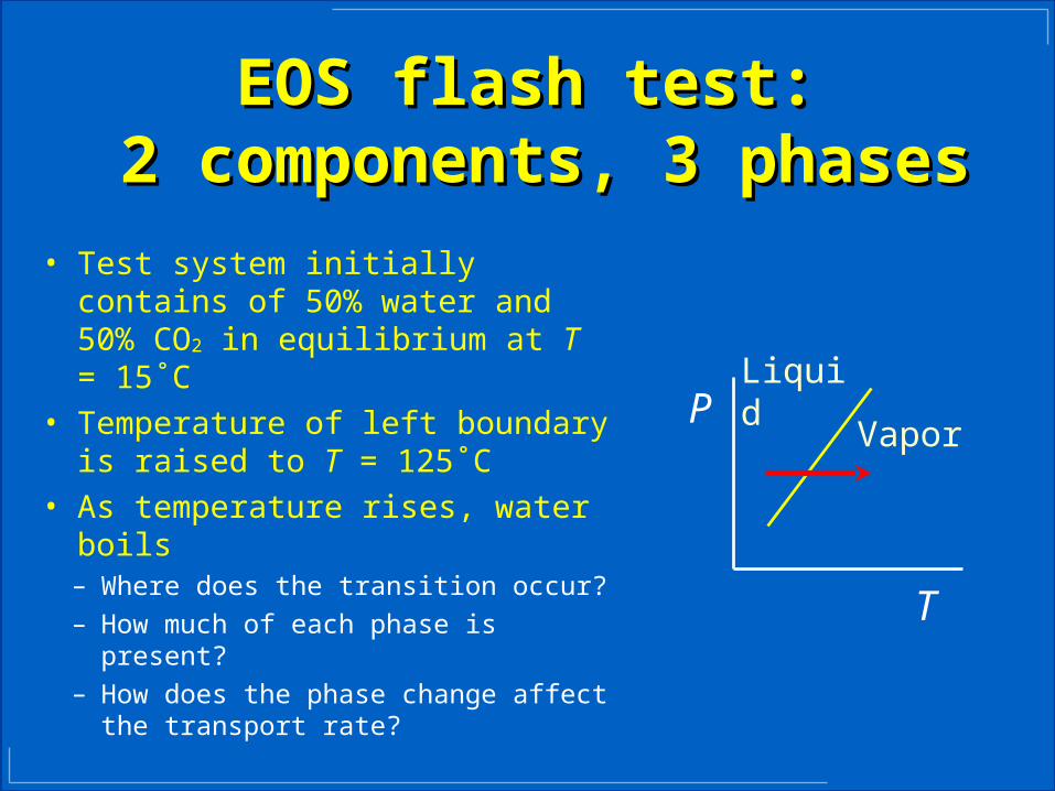
EOS flash test: EOS flash test: 2 components, 3 phases2 components, 3 phases
• Test system initially contains of 50% water and 50% CO2 in equilibrium at T = 15˚C
• Temperature of left boundary is raised to T = 125˚C
• As temperature rises, water boils– Where does the transition occur?– How much of each phase is present?– How does the phase change affect the
transport rate?
LiquidVapor
P
T
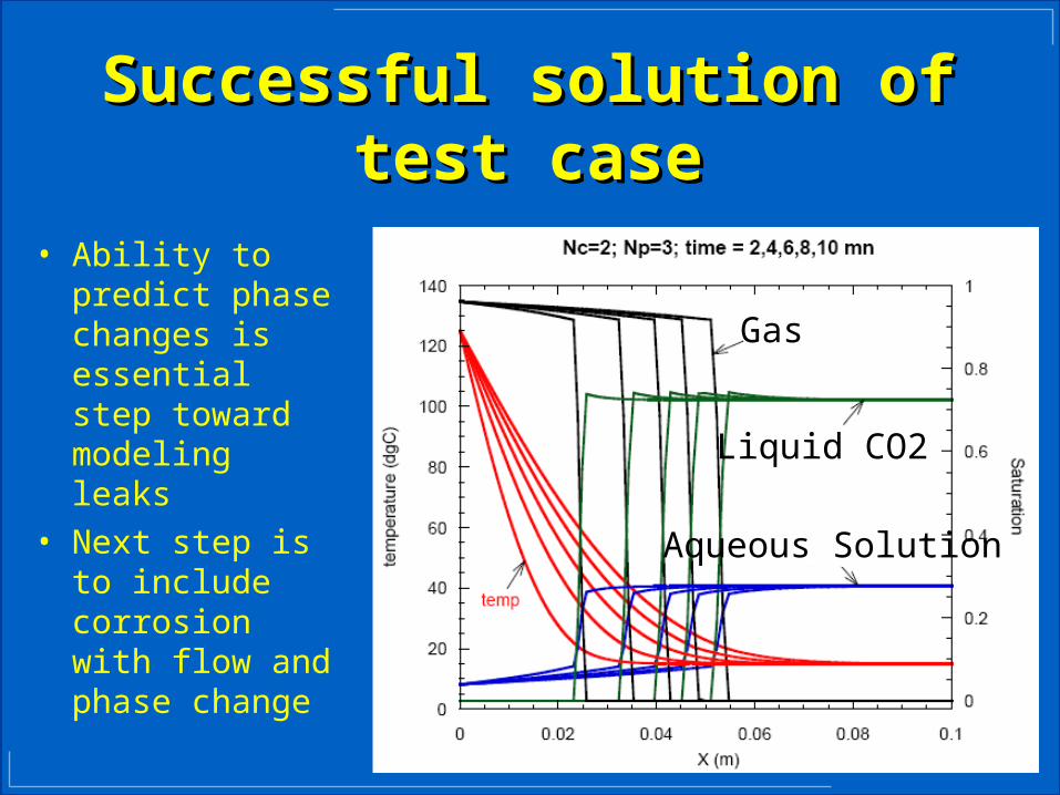
Successful solution of test caseSuccessful solution of test case
Gas
Liquid CO2
Aqueous Solution
• Ability to predict phase changes is essential step toward modeling leaks
• Next step is to include corrosion with flow and phase change
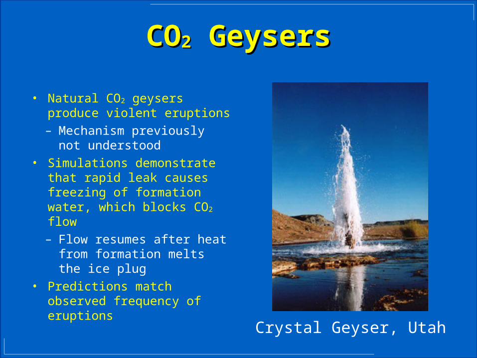
COCO22 Geysers Geysers
• Natural CO2 geysers produce violent eruptions– Mechanism previously not
understood• Simulations demonstrate that
rapid leak causes freezing of formation water, which blocks CO2 flow– Flow resumes after heat
from formation melts the ice plug
• Predictions match observed frequency of eruptions
Crystal Geyser, Utah

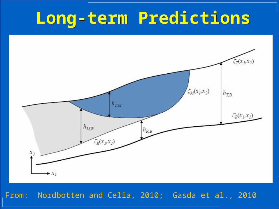
Long-term PredictionsLong-term Predictions
slope
H
hc time
hr
ω
From: Gasda et al., 2010
Long-term PredictionsLong-term Predictions
From: Nordbotten and Celia, 2010; Gasda et al., 2010
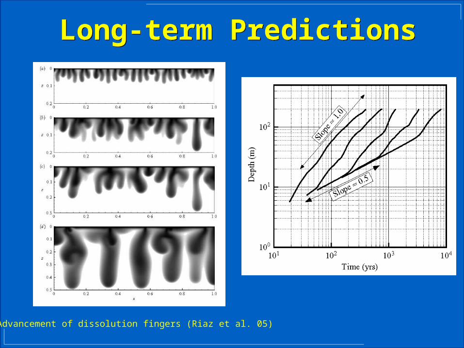
Long-term PredictionsLong-term Predictions
Advancement of dissolution fingers (Riaz et al. 05)
Long-term PredictionsLong-term Predictions

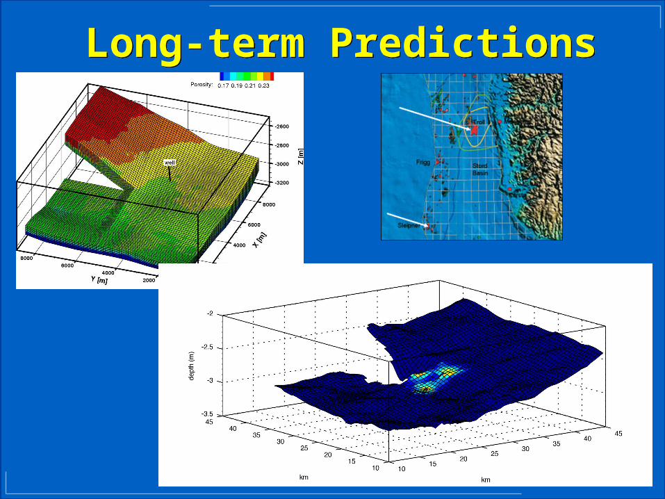
Numerical results of residual and solubility trapping in the Johansen formation during a 3,000-year post-injection period. The colored scale shows porosity. The contours indicate the outer edge of the different CO2 regions (mobile, residual, dissolved) within the subregion indicated in the figure.
Results from Gasda et al., 2010.
Long-term PredictionsLong-term Predictions
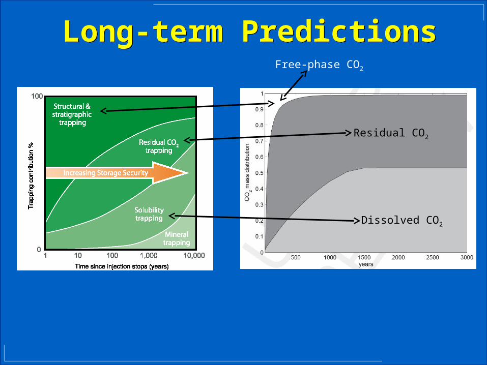
Residual CO2
Dissolved CO2
Free-phase CO2

Key InformationKey Information
3. What is the Area of Review?
Follows EPA UIC Approach.
Determined by pressure perturbations, not CO2 plume.
Diffuse leakage becomes important.
Boundary conditions are likely to be important.
4. How can systems be engineered to improve performance?
Design Injection wells to minimize (1) pressure at wells and (2) Area of Review.Extract brine to manage pressure, provide water for surface facilities.
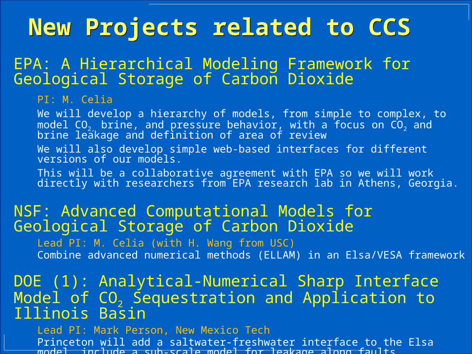
New Projects related to CCSNew Projects related to CCS
EPA: A Hierarchical Modeling Framework for Geological Storage of Carbon Dioxide
PI: M. CeliaWe will develop a hierarchy of models, from simple to complex, to model CO2, brine, and pressure behavior, with a focus on CO2 and brine leakage and definition of area of reviewWe will also develop simple web-based interfaces for different versions of our models.This will be a collaborative agreement with EPA so we will work directly with researchers from EPA research lab in Athens, Georgia.
NSF: Advanced Computational Models for Geological Storage of Carbon Dioxide
Lead PI: M. Celia (with H. Wang from USC)Combine advanced numerical methods (ELLAM) in an Elsa/VESA framework
DOE (1): Analytical-Numerical Sharp Interface Model of CO2 Sequestration and Application to Illinois Basin
Lead PI: Mark Person, New Mexico TechPrinceton will add a saltwater-freshwater interface to the Elsa model, include a sub-scale model for leakage along faults, andparticipate in modeling of the Illinois Basin.New Mexico Tech, Princeton, Illinois Geol Survey, Indiana University, Los Alamos.

New Projects related to CCSNew Projects related to CCS
DOE (2): Quantification of Wellbore Leakage Risk using Nondestructive Borehole Logging Techniques
Lead PI: Andrew Duguid, SchlumbergerPrinceton will perform data analysis and develop software for parameter estimation.Schlumberger, Los Alamos, and Princeton
DOE (3): Basin-Scale Leakage Risks from Geologic Carbon Sequestration: Impact on CCS Energy Market Competitiveness
Lead PI: Catherine Peters, PrincetonOur group will apply the Elsa code to model the Michigan Basin. We may also contribute to efforts to couple Else to geochemical reaction models.Princeton, University of Minnesota, Brookhaven Natl. Lab.
DOE (4): Upscaling Geochemical Reaction Rates for CO2 in Deep Saline Aquifers
Lead PI: Catherine Peters, Princeton
NSF: DUSEL - Large-scale field experimentsLead PI: Catherine Peters, Princeton
Thank You!
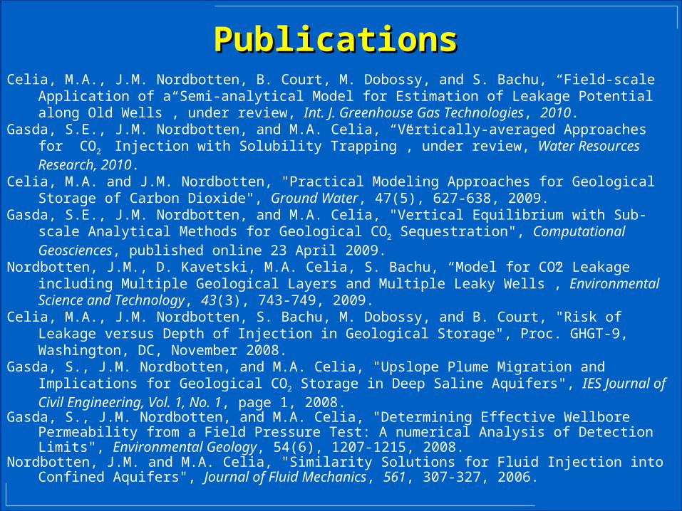
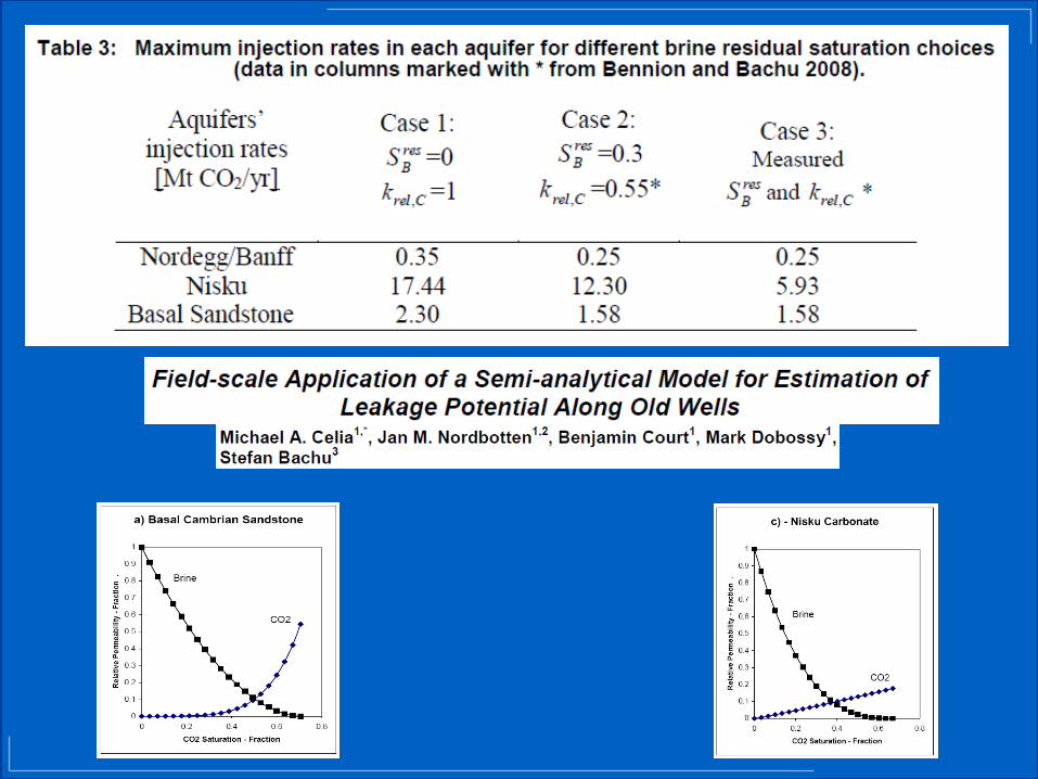
PublicationsPublicationsCelia, M.A., J.M. Nordbotten, B. Court, M. Dobossy, and S. Bachu, “Field-scale Application of a
Semi-analytical Model for Estimation of Leakage Potential along Old Wells”, under review, Int. J. Greenhouse Gas Technologies, 2010.
Gasda, S.E., J.M. Nordbotten, and M.A. Celia, “Vertically-averaged Approaches for CO2 Injection with Solubility Trapping”, under review, Water Resources Research, 2010.
Celia, M.A. and J.M. Nordbotten, "Practical Modeling Approaches for Geological Storage of Carbon Dioxide", Ground Water, 47(5), 627-638, 2009.
Gasda, S.E., J.M. Nordbotten, and M.A. Celia, "Vertical Equilibrium with Sub-scale Analytical Methods for Geological CO2 Sequestration", Computational Geosciences, published online 23 April 2009.
Nordbotten, J.M., D. Kavetski, M.A. Celia, S. Bachu, “Model for CO2 Leakage including Multiple Geological Layers and Multiple Leaky Wells”, Environmental Science and Technology, 43(3), 743-749, 2009.
Celia, M.A., J.M. Nordbotten, S. Bachu, M. Dobossy, and B. Court, "Risk of Leakage versus Depth of Injection in Geological Storage", Proc. GHGT-9, Washington, DC, November 2008.
Gasda, S., J.M. Nordbotten, and M.A. Celia, "Upslope Plume Migration and Implications for Geological CO2 Storage in Deep Saline Aquifers", IES Journal of Civil Engineering, Vol. 1, No. 1, page 1, 2008.
Gasda, S., J.M. Nordbotten, and M.A. Celia, "Determining Effective Wellbore Permeability from a Field Pressure Test: A numerical Analysis of Detection Limits", Environmental Geology, 54(6), 1207-1215, 2008.
Nordbotten, J.M. and M.A. Celia, "Similarity Solutions for Fluid Injection into Confined Aquifers", Journal of Fluid Mechanics, 561, 307-327, 2006.

Current Modeling Current Modeling
• Injection Period: Elsa Version 1.0– Injection and leakage including multiple layers and
multiple wells.– Expanding to hybrid numerical-analytical
framework.– Diffuse leakage in pressure responses.
• Post-injection Period– Large-scale (upscaled) dissolution and convective
mixing– Inclusion of capillary fringe – expansion of sharp
interface still with vertical equilibrium
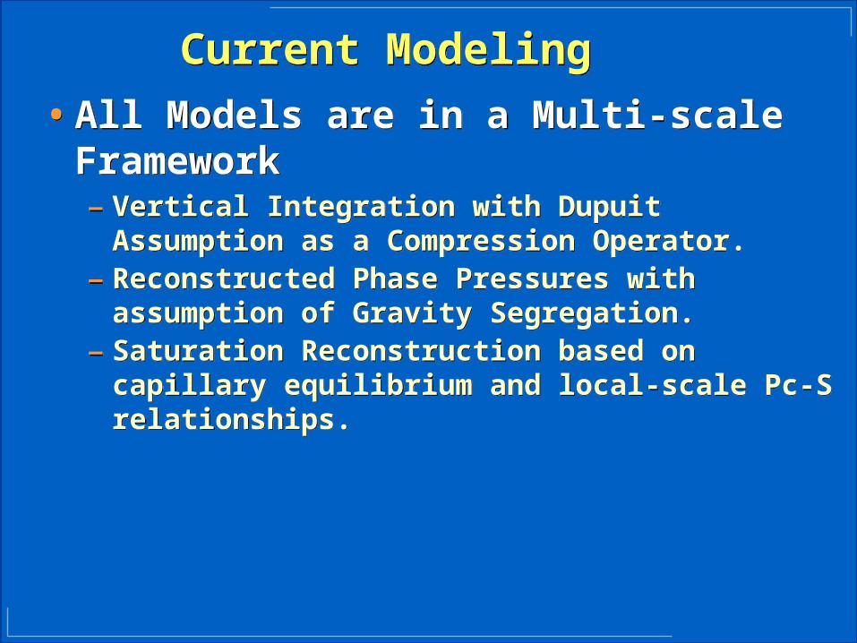
Current Modeling Current Modeling
• All Models are in a Multi-scale Framework– Vertical Integration with Dupuit Assumption as a
Compression Operator.– Reconstructed Phase Pressures with assumption of
Gravity Segregation.– Saturation Reconstruction based on capillary
equilibrium and local-scale Pc-S relationships.
• All Models are in a Multi-scale Framework– Vertical Integration with Dupuit Assumption as a
Compression Operator.– Reconstructed Phase Pressures with assumption of
Gravity Segregation.– Saturation Reconstruction based on capillary
equilibrium and local-scale Pc-S relationships.
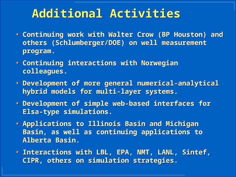
Additional Activities Additional Activities
• Continuing work with Walter Crow (BP Houston) and others (Schlumberger/DOE) on well measurement program.
• Continuing interactions with Norwegian colleagues.
• Development of more general numerical-analytical hybrid models for multi-layer systems.
• Development of simple web-based interfaces for Elsa-type simulations.
• Applications to Illinois Basin and Michigan Basin, as well as continuing applications to Alberta Basin.
• Interactions with LBL, EPA, NMT, LANL, Sintef, CIPR, others on simulation strategies.
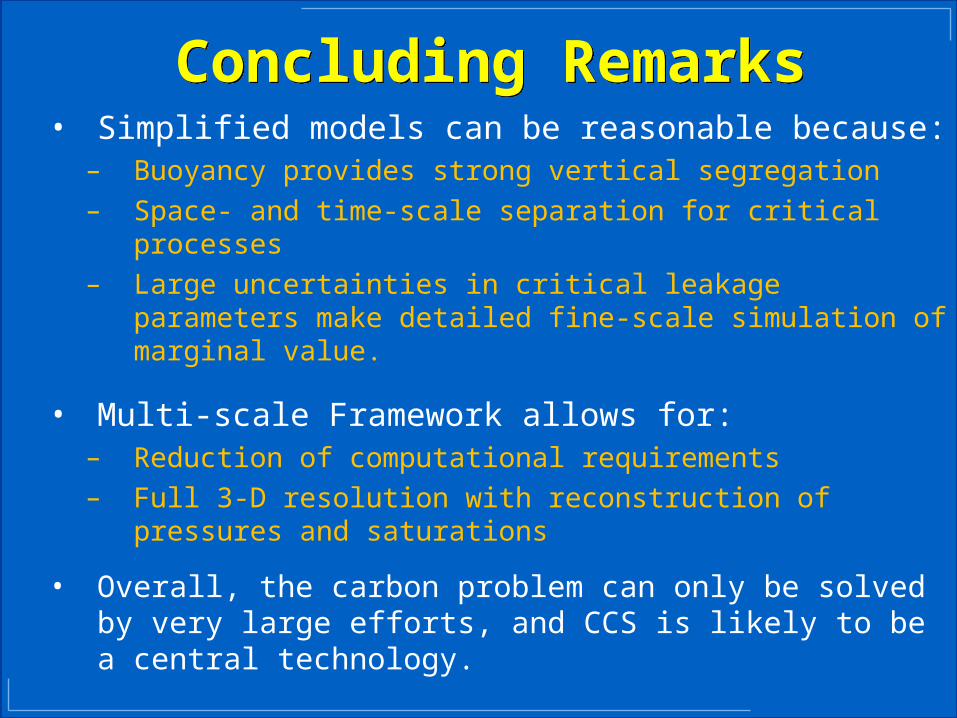
Concluding RemarksConcluding Remarks• Simplified models can be reasonable because:
– Buoyancy provides strong vertical segregation– Space- and time-scale separation for critical processes– Large uncertainties in critical leakage parameters make
detailed fine-scale simulation of marginal value.
• Multi-scale Framework allows for:– Reduction of computational requirements– Full 3-D resolution with reconstruction of pressures and
saturations
• Overall, the carbon problem can only be solved by very large efforts, and CCS is likely to be a central technology.