Embed Size (px)
Citation preview
Geographical analysis and Geographical analysis and numerical quantification numerical quantification
of visual impact for aerogenerators of visual impact for aerogenerators and photovoltaic panels and photovoltaic panels using Open Source GISusing Open Source GIS
A. Minelli, A. Minelli, I. Marchesini,I. Marchesini, P. De Rosa, L. Casagrande & M. Cenci P. De Rosa, L. Casagrande & M. Cenci
Gfosservices Gfosservices Studio AssociatoStudio Associato
Regione Regione UmbriaUmbria
Gfosservices Gfosservices
Studio AssociatoStudio AssociatoRegione Regione UmbriaUmbria
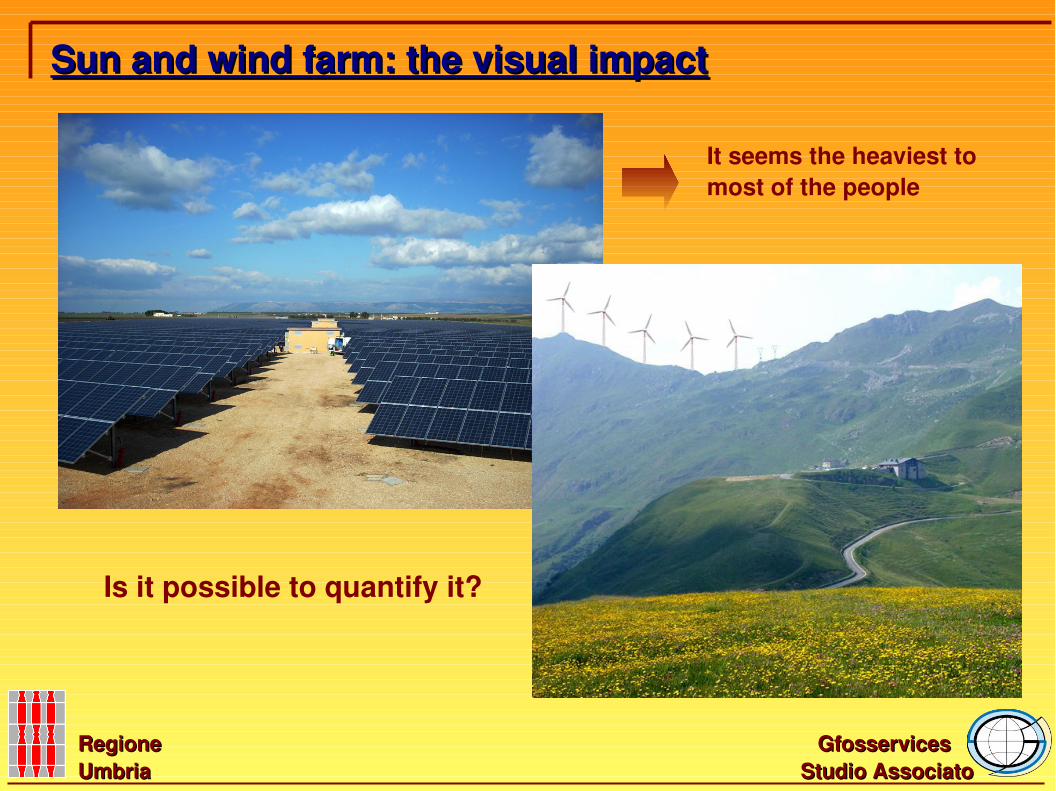
Sun and wind farm: the visual impactSun and wind farm: the visual impact
It seems the heaviest tomost of the people
Is it possible to quantify it?
To quantitatively define the visual impact we developed a GRASS GISGRASS GIS module:module:
Gfosservices Gfosservices Studio AssociatoStudio Associato
Regione Regione UmbriaUmbria
r.wind.sunr.wind.sun
Visibility quantificationVisibility quantification
Gfosservices Gfosservices
Studio AssociatoStudio AssociatoRegione Regione UmbriaUmbria
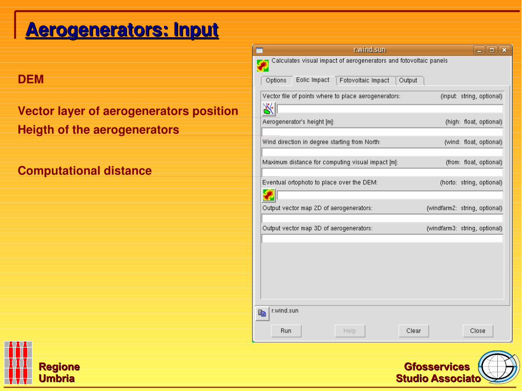
Aerogenerators: InputAerogenerators: Input
Vector layer of aerogenerators positionHeigth of the aerogenerators
Computational distance
DEM
Gfosservices Gfosservices
Studio AssociatoStudio AssociatoRegione Regione UmbriaUmbria
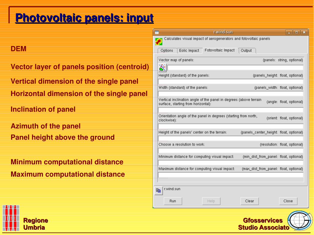
Photovoltaic panels: inputPhotovoltaic panels: input
Vertical dimension of the single panel
Maximum computational distance
Panel height above the ground
Horizontal dimension of the single panel
Inclination of panel
Azimuth of the panel
Minimum computational distance
Vector layer of panels position (centroid)
DEM
Gfosservices Gfosservices
Studio AssociatoStudio AssociatoRegione Regione UmbriaUmbria
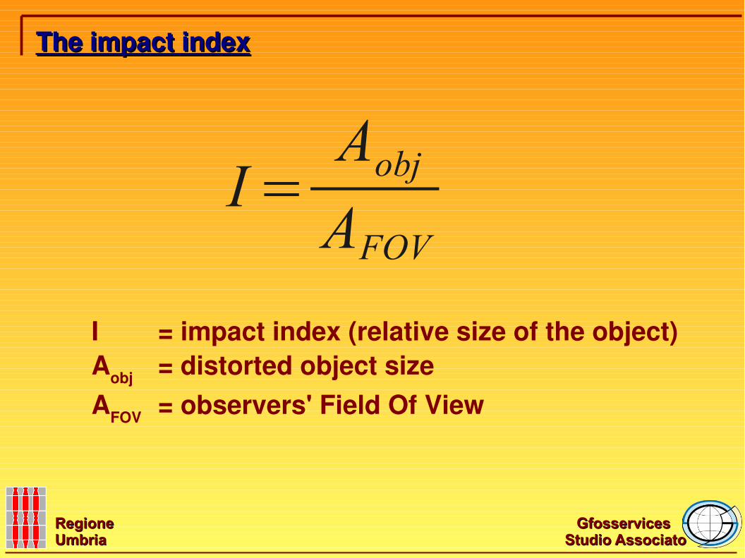
I = impact index (relative size of the object)Aobj = distorted object sizeAFOV = observers' Field Of View
The impact indexThe impact index
I=AobjAFOV
Gfosservices Gfosservices
Studio AssociatoStudio AssociatoRegione Regione UmbriaUmbria
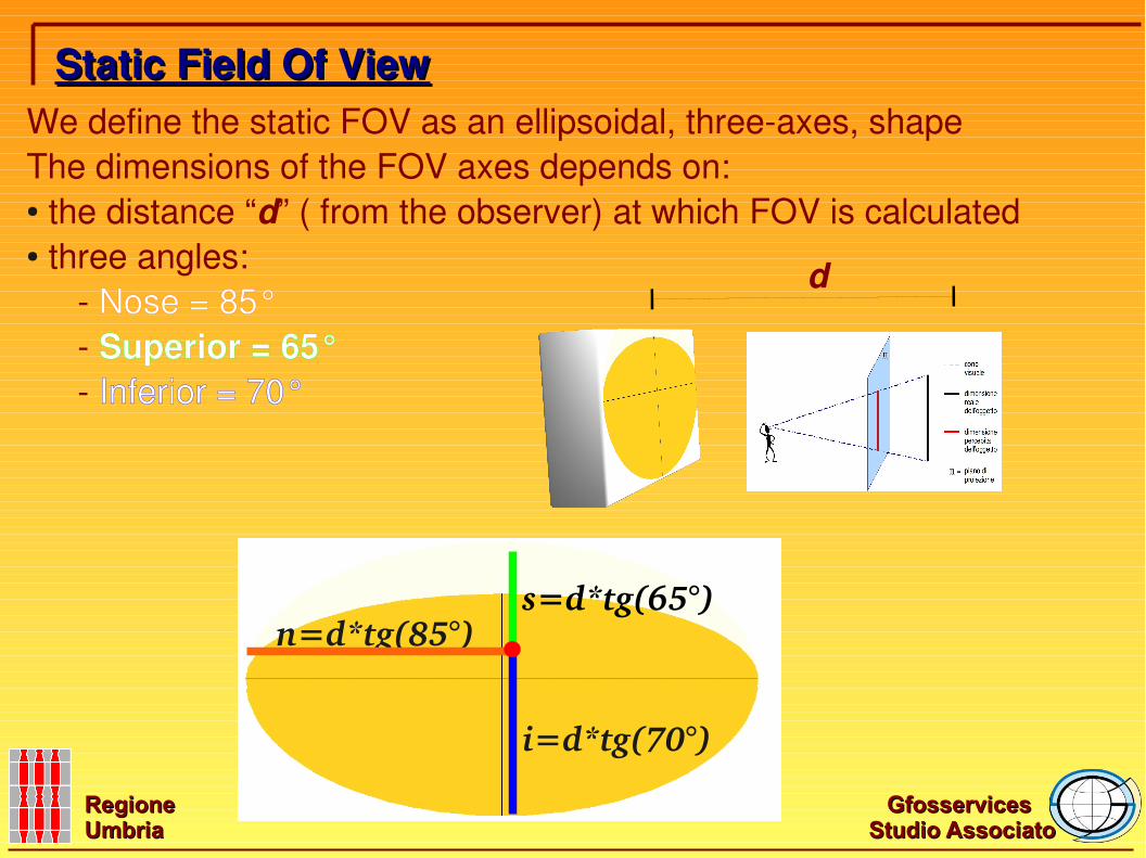
We define the static FOV as an ellipsoidal, three-axes, shapeThe dimensions of the FOV axes depends on: ● the distance “d” ( from the observer) at which FOV is calculated● three angles: - Nose = 85° - Superior = 65° - Inferior = 70°
i=d*tg(70°)
s=d*tg(65°)n=d*tg(85°)
Static Field Of ViewStatic Field Of View
d
Gfosservices Gfosservices
Studio AssociatoStudio AssociatoRegione Regione UmbriaUmbria
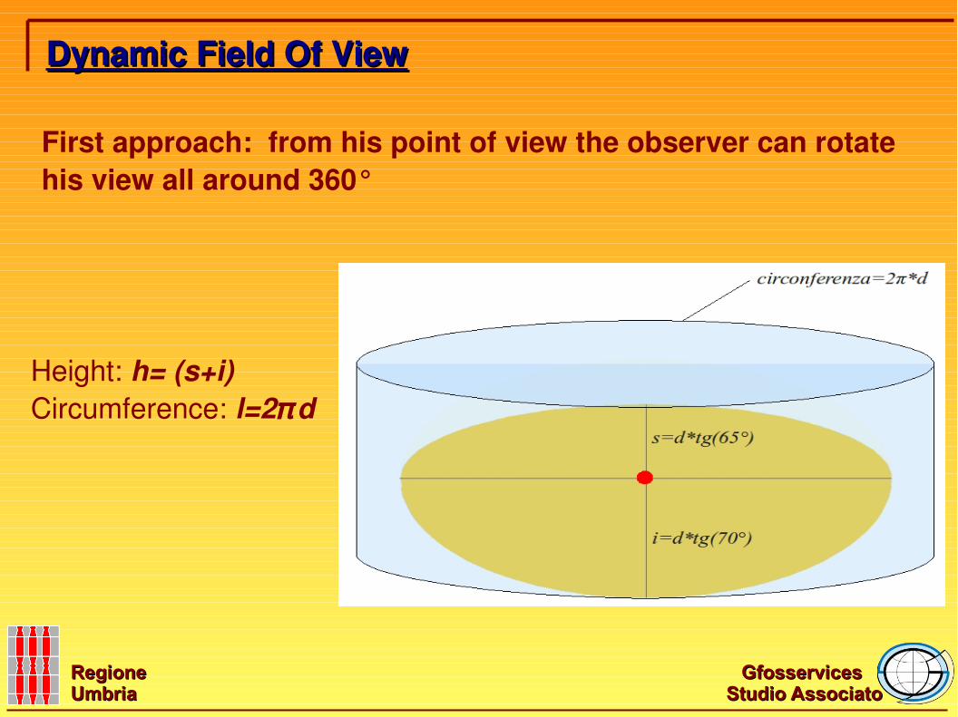
First approach: from his point of view the observer can rotate his view all around 360°
Dynamic Field Of ViewDynamic Field Of View
Height: h= (s+i)Circumference: l=2πd
Gfosservices Gfosservices
Studio AssociatoStudio AssociatoRegione Regione UmbriaUmbria
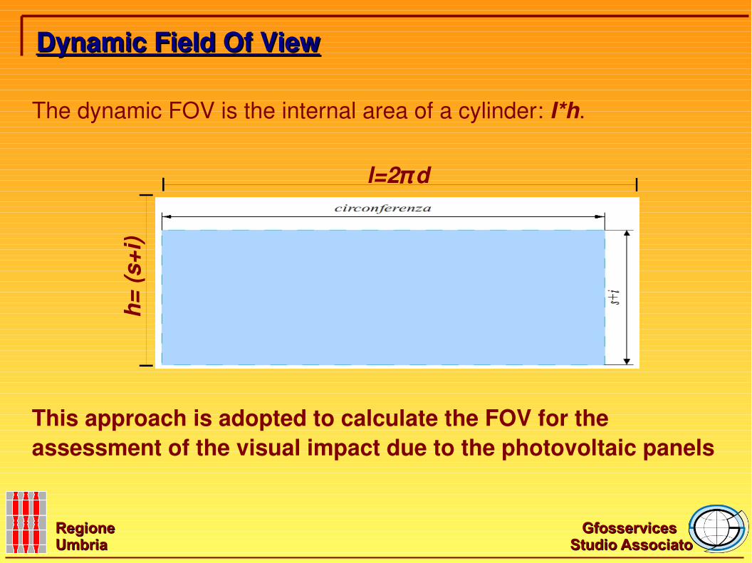
The dynamic FOV is the internal area of a cylinder: I*h.
Dynamic Field Of ViewDynamic Field Of View
h= (s
+i)
l=2πd
This approach is adopted to calculate the FOV for the assessment of the visual impact due to the photovoltaic panels
Gfosservices Gfosservices
Studio AssociatoStudio AssociatoRegione Regione UmbriaUmbria
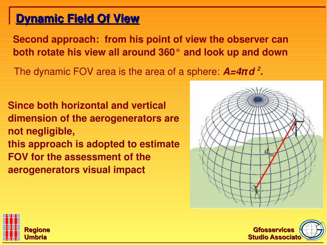
Second approach: from his point of view the observer can both rotate his view all around 360° and look up and down
The dynamic FOV area is the area of a sphere: A=4πd 2.
Dynamic Field Of ViewDynamic Field Of View
Since both horizontal and vertical dimension of the aerogenerators are not negligible, this approach is adopted to estimate FOV for the assessment of the aerogenerators visual impact
Gfosservices Gfosservices
Studio AssociatoStudio AssociatoRegione Regione UmbriaUmbria
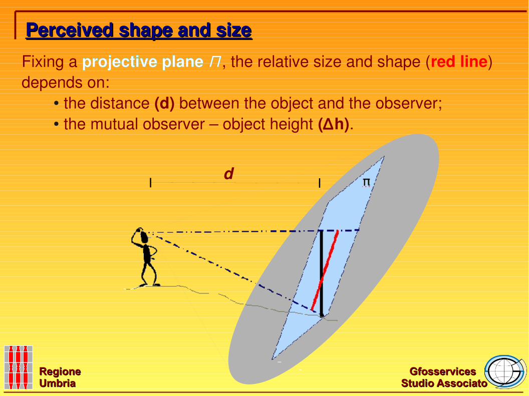
Perceived shape and sizePerceived shape and size
Fixing a projective plane Π , the relative size and shape (red line) depends on:
● the distance (d) between the object and the observer;● the mutual observer – object height (∆h).
d
Gfosservices Gfosservices
Studio AssociatoStudio AssociatoRegione Regione UmbriaUmbria
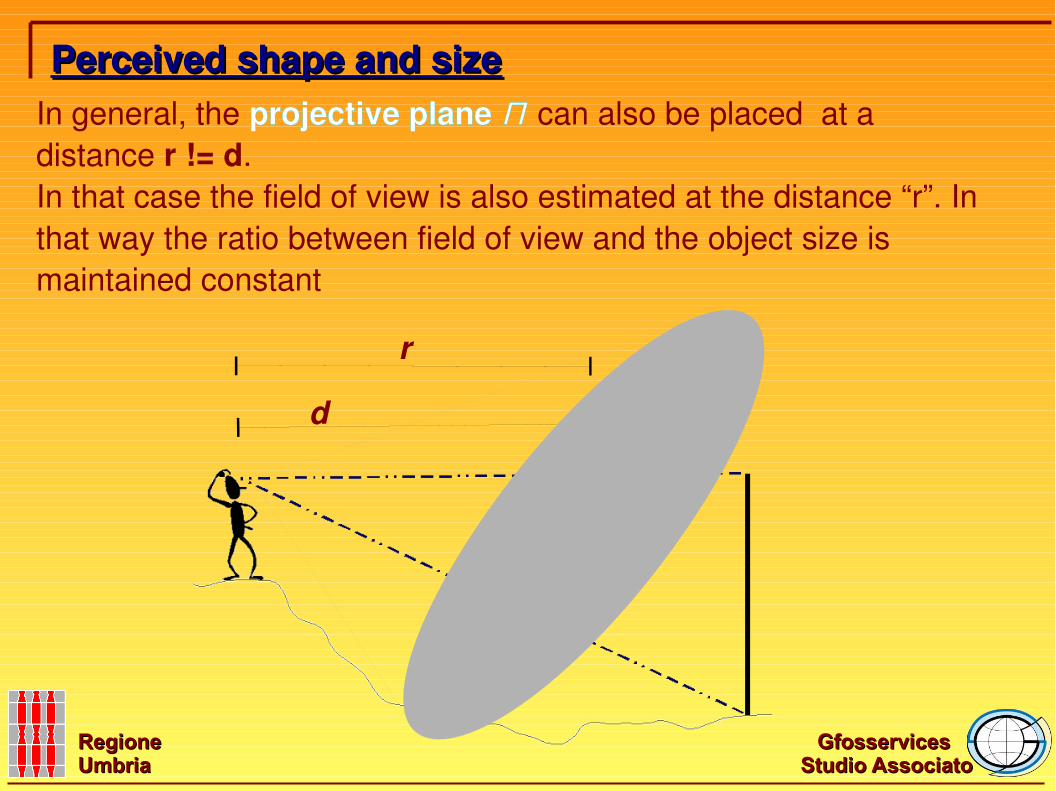
Perceived shape and sizePerceived shape and sizeIn general, the projective plane Π can also be placed at a distance r != d.In that case the field of view is also estimated at the distance “r”. In that way the ratio between field of view and the object size is maintained constant
d
r
Gfosservices Gfosservices
Studio AssociatoStudio AssociatoRegione Regione UmbriaUmbria
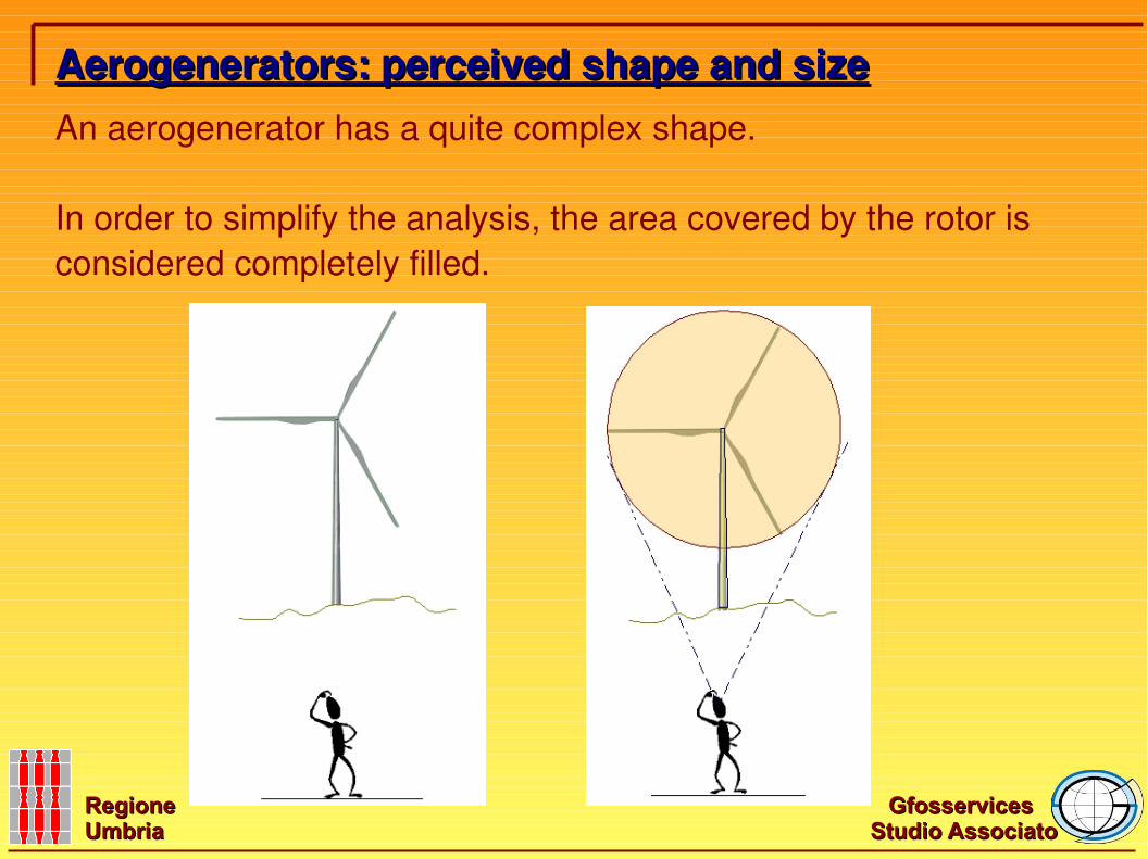
An aerogenerator has a quite complex shape.
In order to simplify the analysis, the area covered by the rotor is considered completely filled.
Aerogenerators: perceived shape and sizeAerogenerators: perceived shape and size
Gfosservices Gfosservices
Studio AssociatoStudio AssociatoRegione Regione UmbriaUmbria
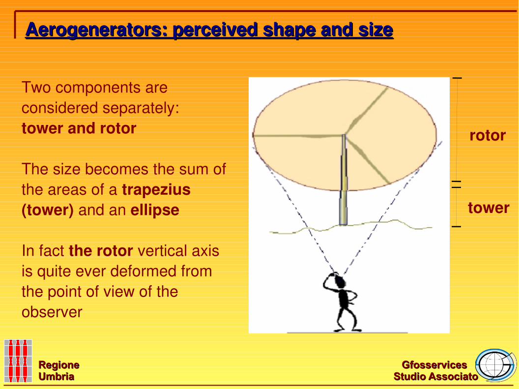
Two components are considered separately: tower and rotor
The size becomes the sum of the areas of a trapezius (tower) and an ellipse
In fact the rotor vertical axis is quite ever deformed from the point of view of the observer
Aerogenerators: perceived shape and sizeAerogenerators: perceived shape and size
tower
rotor
Gfosservices Gfosservices
Studio AssociatoStudio AssociatoRegione Regione UmbriaUmbria
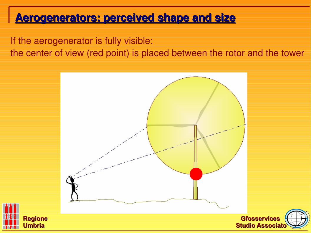
If the aerogenerator is fully visible:the center of view (red point) is placed between the rotor and the tower
Aerogenerators: perceived shape and sizeAerogenerators: perceived shape and size
Gfosservices Gfosservices
Studio AssociatoStudio AssociatoRegione Regione UmbriaUmbria
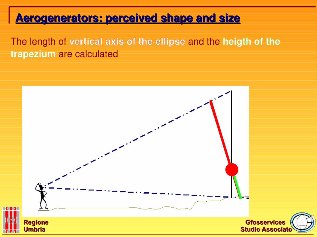
The length of vertical axis of the ellipse and the heigth of the trapezium are calculated
Aerogenerators: perceived shape and sizeAerogenerators: perceived shape and size
Gfosservices Gfosservices
Studio AssociatoStudio AssociatoRegione Regione UmbriaUmbria
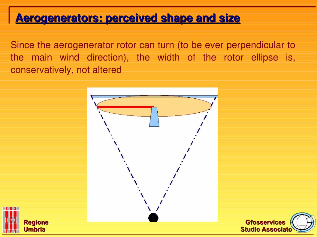
Since the aerogenerator rotor can turn (to be ever perpendicular to the main wind direction), the width of the rotor ellipse is, conservatively, not altered
Aerogenerators: perceived shape and sizeAerogenerators: perceived shape and size
Gfosservices Gfosservices
Studio AssociatoStudio AssociatoRegione Regione UmbriaUmbria
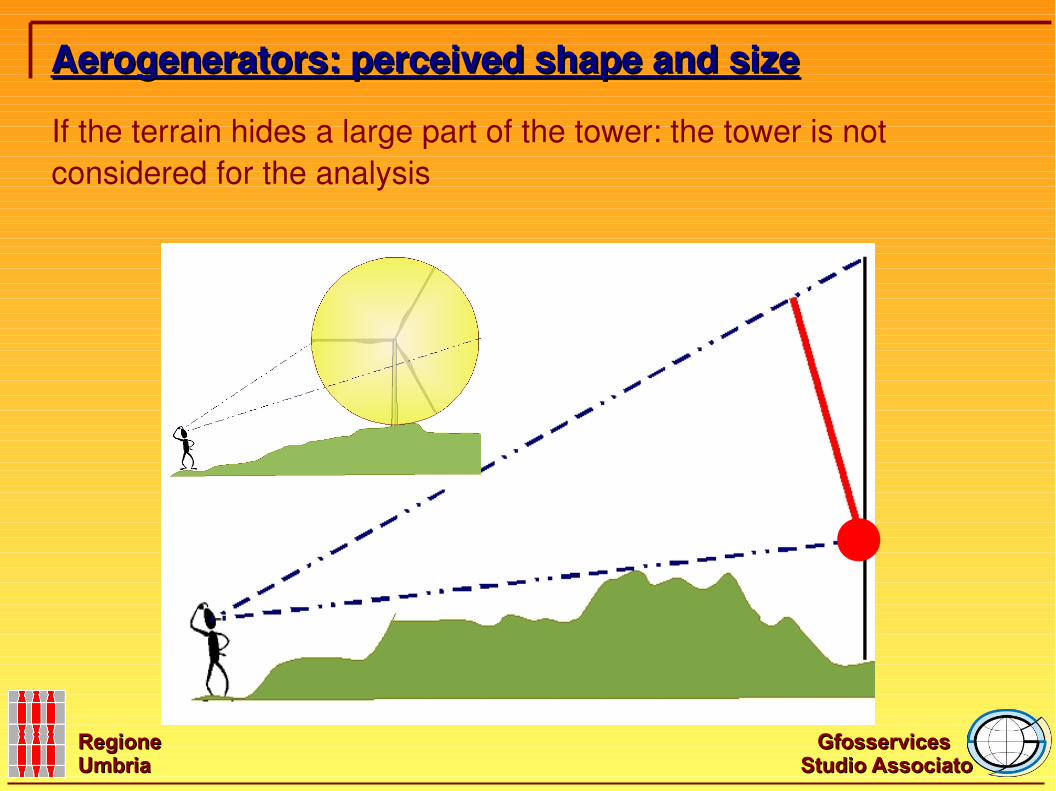
Aerogenerators: perceived shape and sizeAerogenerators: perceived shape and size
If the terrain hides a large part of the tower: the tower is not considered for the analysis
Gfosservices Gfosservices
Studio AssociatoStudio AssociatoRegione Regione UmbriaUmbria
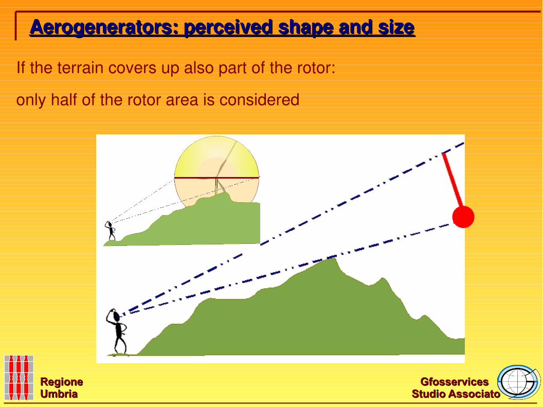
If the terrain covers up also part of the rotor:
only half of the rotor area is considered
Aerogenerators: perceived shape and sizeAerogenerators: perceived shape and size
Gfosservices Gfosservices
Studio AssociatoStudio AssociatoRegione Regione UmbriaUmbria
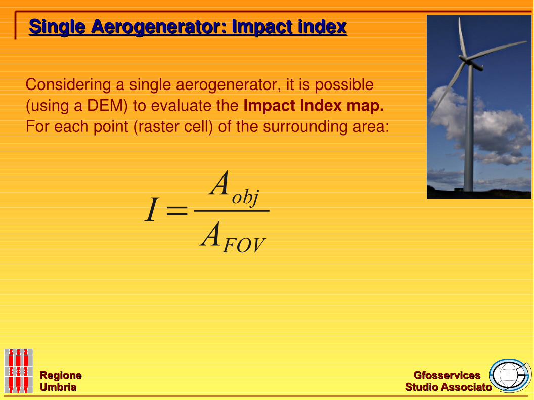
Considering a single aerogenerator, it is possible (using a DEM) to evaluate the Impact Index map.For each point (raster cell) of the surrounding area:
Single Aerogenerator: Impact indexSingle Aerogenerator: Impact index
I=AobjAFOV
Gfosservices Gfosservices
Studio AssociatoStudio AssociatoRegione Regione UmbriaUmbria
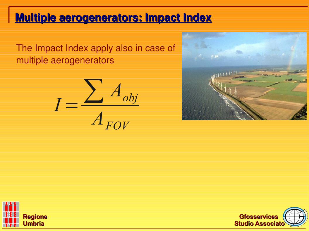
The Impact Index apply also in case of multiple aerogenerators
Multiple aerogenerators: Impact IndexMultiple aerogenerators: Impact Index
I=∑ AobjAFOV
Gfosservices Gfosservices
Studio AssociatoStudio AssociatoRegione Regione UmbriaUmbria
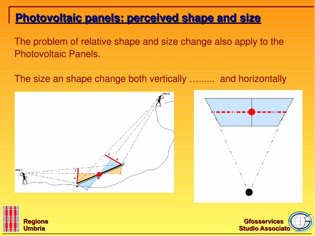
Photovoltaic panels: perceived shape and sizePhotovoltaic panels: perceived shape and size
The problem of relative shape and size change also apply to the Photovoltaic Panels.
The size an shape change both vertically …...... and horizontally
Gfosservices Gfosservices
Studio AssociatoStudio AssociatoRegione Regione UmbriaUmbria
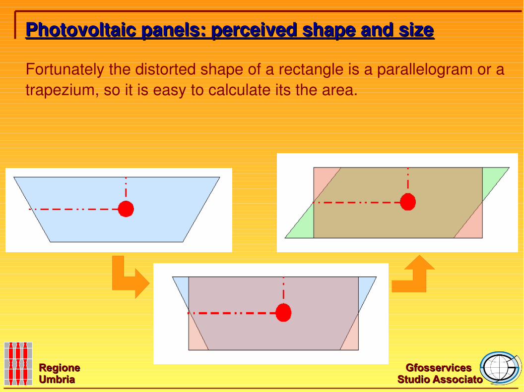
Photovoltaic panels: perceived shape and sizePhotovoltaic panels: perceived shape and size
Fortunately the distorted shape of a rectangle is a parallelogram or a trapezium, so it is easy to calculate its the area.
Gfosservices Gfosservices
Studio AssociatoStudio AssociatoRegione Regione UmbriaUmbria
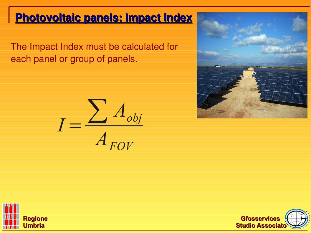
The Impact Index must be calculated for each panel or group of panels.
Photovoltaic panels: Impact IndexPhotovoltaic panels: Impact Index
I=∑ AobjAFOV
Gfosservices Gfosservices
Studio AssociatoStudio AssociatoRegione Regione UmbriaUmbria
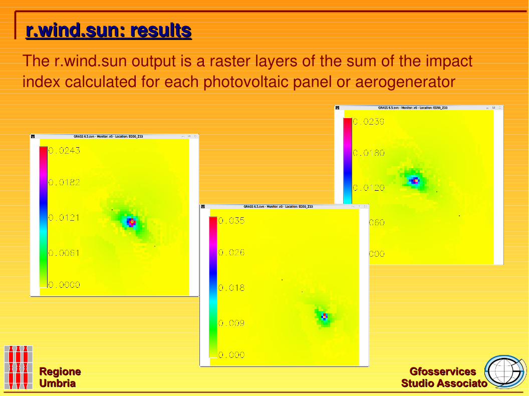
r.wind.sun: resultsr.wind.sun: resultsThe r.wind.sun output is a raster layers of the sum of the impact index calculated for each photovoltaic panel or aerogenerator
Gfosservices Gfosservices
Studio AssociatoStudio AssociatoRegione Regione UmbriaUmbria
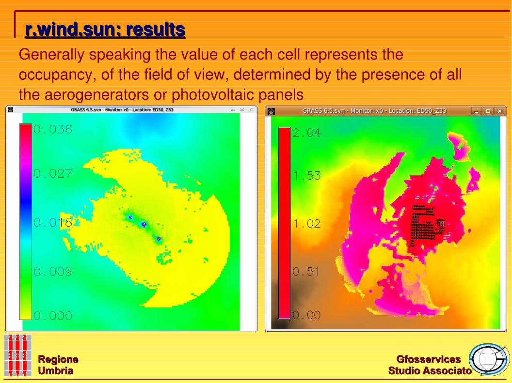
r.wind.sun: resultsr.wind.sun: resultsGenerally speaking the value of each cell represents the occupancy, of the field of view, determined by the presence of all the aerogenerators or photovoltaic panels
Gfosservices Gfosservices
Studio AssociatoStudio AssociatoRegione Regione UmbriaUmbria
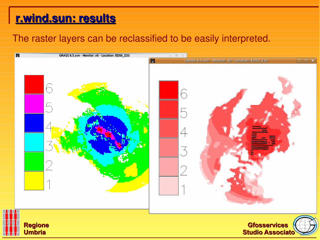
The raster layers can be reclassified to be easily interpreted.
r.wind.sun: resultsr.wind.sun: results
Gfosservices Gfosservices
Studio AssociatoStudio AssociatoRegione Regione UmbriaUmbria
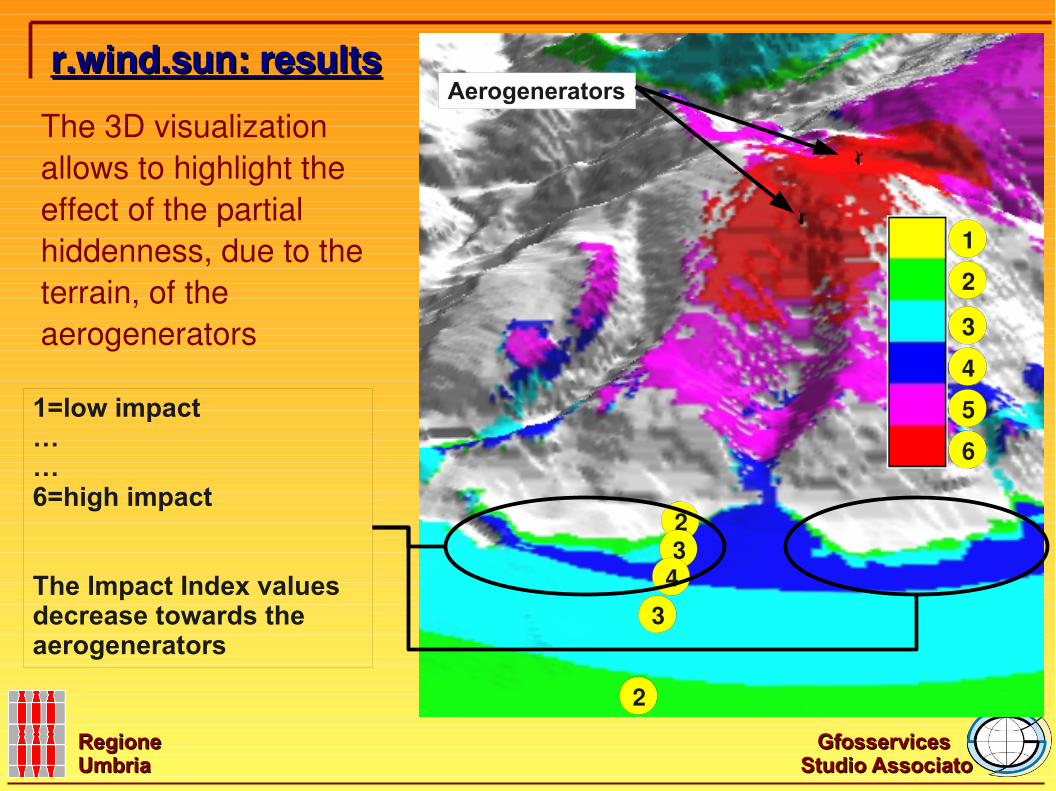
The 3D visualization allows to highlight the effect of the partial hiddenness, due to the terrain, of the aerogenerators
r.wind.sun: resultsr.wind.sun: results
23
43
2
2
3
4
5
6
1
Aerogenerators
1=low impact……6=high impact
The Impact Index values decrease towards the aerogenerators
Gfosservices Gfosservices
Studio AssociatoStudio AssociatoRegione Regione UmbriaUmbria
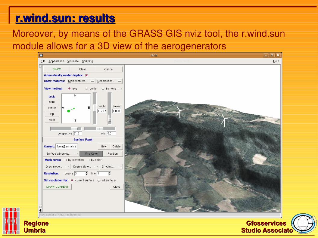
Moreover, by means of the GRASS GIS nviz tool, the r.wind.sun module allows for a 3D view of the aerogenerators
r.wind.sun: resultsr.wind.sun: results
Gfosservices Gfosservices
Studio AssociatoStudio AssociatoRegione Regione UmbriaUmbria
● The module r.wind.sun is a preliminary answer to the question concerning the possibility to estimate the visual impact of aerogenerators and photovoltaic panels● We acknowledge that the relative dimension is only a part of the visual impact assessment● We put in evidence that this method can be used for other kinds of landscape offending structures ● We emphasize that, using a common field of view approach, the results obtained for different kind of structures, that exist on the same territory, can be combined.
r.wind.sun: conclusionsr.wind.sun: conclusions
Gfosservices Gfosservices
Studio AssociatoStudio AssociatoRegione Regione UmbriaUmbria
r.wind.sun: downloadr.wind.sun: download
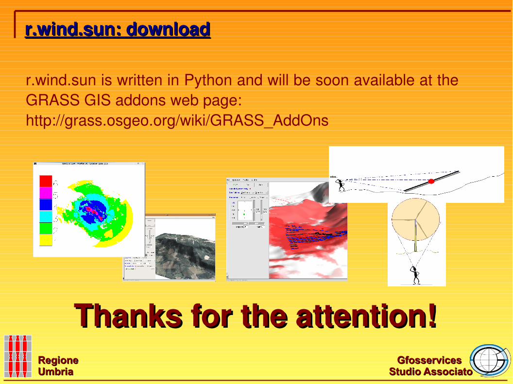
r.wind.sun is written in Python and will be soon available at the GRASS GIS addons web page:http://grass.osgeo.org/wiki/GRASS_AddOns
Thanks for the attention!Thanks for the attention!