Embed Size (px)
Citation preview
Widening and deepening adjacent large shafts in rock
E. C. Antonio and N. L. Adams
The influent pumping station (IPS) at Bandra plays a keyrole in the Mumbai Sewerage Scheme. Bandra IPS willbe one of the largest pumping stations of its type in theworld, with a pumping capacity of nearly 22 m3/s. Therock support scheme for the widening and deepening ofthree existing shafts is described, with particular atten-tion being given to the scheme for the narrow zone ofrock between the two pump shafts, termed the ‘narrowneck’. Inherent site conditions and the demands of a newstation on a prescribed station layout have placed un-usual constraints on the customary rock support meth-odology. Several excavation and rock supportalternatives are discussed and the limitations of routinedesign methods are highlighted. The finally agreedscheme was a progressive and carefully planned rocksupport and excavation sequence that considered thepossibility of localised instability during the excavationworks and provided contingencies for several possibleevents. A concrete bridge was constructed to restrainthe existing retaining walls and through-going groutedbolts continuously supported the whole rock section,before, during and after excavation. Inspection andmonitoring was completed before each stage of excava-tion. The rock face and retaining walls remained intactand no serious failures were experienced during excava-tion. A brief discussion of possible rock design alterna-tives, given a virgin site of similar rock, follows theconclusions. Rock excavations are now complete and thecivil works at Bandra IPS are nearing completion.
1. INTRODUCTIONIndia’s largest city is situated on the north-west coast of India,
in the state of Maharashtra. The population of Mumbai
(formerly known as Bombay) has expanded rapidly to about 13
million and is expected to grow significantly over the coming
years. Since the early 1980s, part-financed by the World Bank,
the Brihan Mumbai Corporation (BMC) has embarked on a
series of major engineering projects to collect and dispose of
sewage from the city through a system of tunnels, pipelines,
pumping stations, treatment facilities and long sea outfalls.
With a total of eight pumps, each rated at 3?2 m3/s, the Bandra
influent pumping station (IPS) will be among the largest of its
kind in the world. Work first commenced on the construction of
the Bandra tunnels, pipelines, pumping stations and treatment
facilities in the early 1980s. However, the contracts ran into
difficulties that finally culminated in their cancellation, with
the works only partially complete; new consultants were then
appointed.
This paper briefly describes some of the background which has
influenced the approach taken in assessing the rock support
needs for the excavations left by previous contracts. This is
followed by the assessment of geological conditions, the
assessment of rock support options and finally, the adopted
rock support scheme is described. A brief discussion of the
works and some hypothetical alternatives conclude the paper.
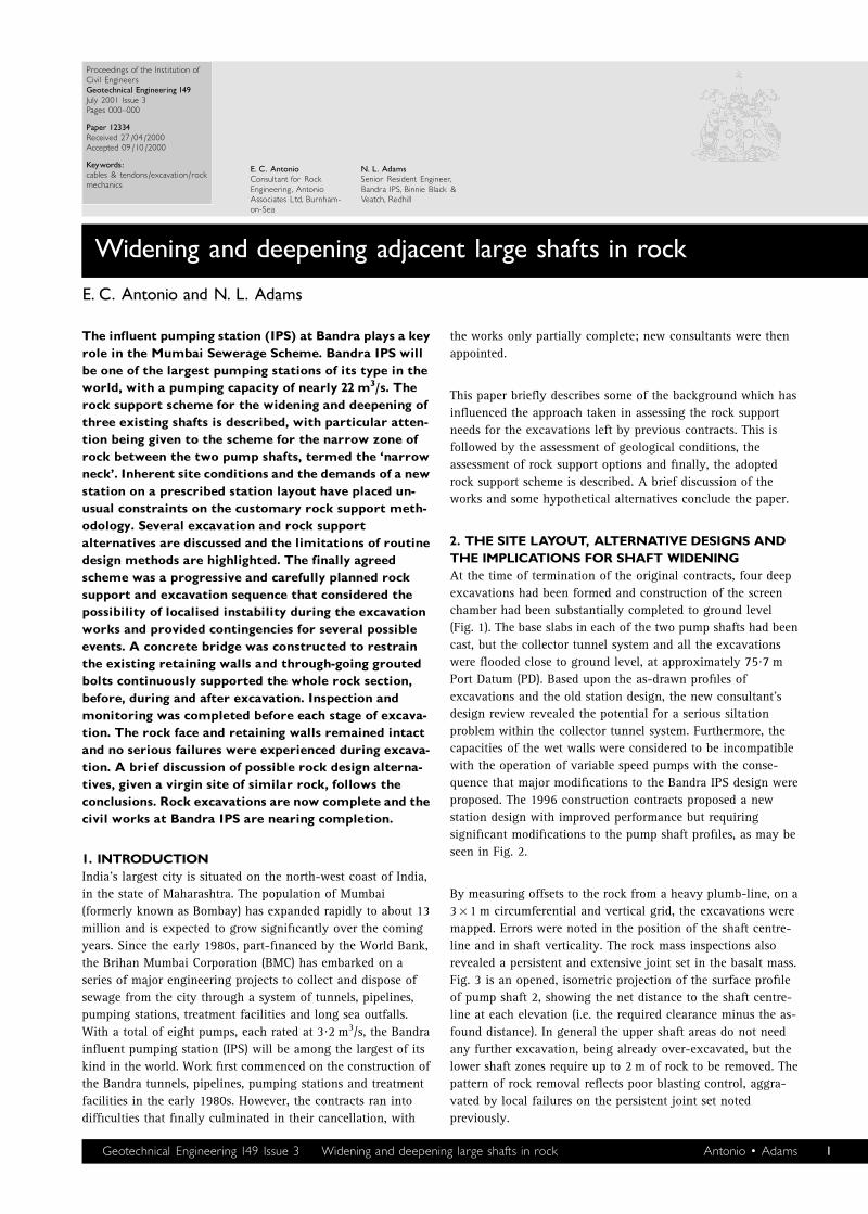
2. THE SITE LAYOUT, ALTERNATIVE DESIGNS ANDTHE IMPLICATIONS FOR SHAFT WIDENINGAt the time of termination of the original contracts, four deep
excavations had been formed and construction of the screen
chamber had been substantially completed to ground level
(Fig. 1). The base slabs in each of the two pump shafts had been
cast, but the collector tunnel system and all the excavations
were flooded close to ground level, at approximately 75?7 m
Port Datum (PD). Based upon the as-drawn profiles of
excavations and the old station design, the new consultant’s
design review revealed the potential for a serious siltation
problem within the collector tunnel system. Furthermore, the
capacities of the wet walls were considered to be incompatible
with the operation of variable speed pumps with the conse-
quence that major modifications to the Bandra IPS design were
proposed. The 1996 construction contracts proposed a new
station design with improved performance but requiring
significant modifications to the pump shaft profiles, as may be
seen in Fig. 2.
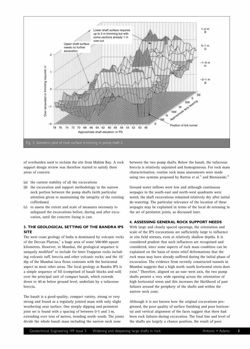
By measuring offsets to the rock from a heavy plumb-line, on a
361 m circumferential and vertical grid, the excavations were
mapped. Errors were noted in the position of the shaft centre-
line and in shaft verticality. The rock mass inspections also
revealed a persistent and extensive joint set in the basalt mass.
Fig. 3 is an opened, isometric projection of the surface profile
of pump shaft 2, showing the net distance to the shaft centre-
line at each elevation (i.e. the required clearance minus the as-
found distance). In general the upper shaft areas do not need
any further excavation, being already over-excavated, but the
lower shaft zones require up to 2 m of rock to be removed. The
pattern of rock removal reflects poor blasting control, aggra-
vated by local failures on the persistent joint set noted
previously.
Proceedings of the Institution ofCivil EngineersGeotechnical Engineering 149July 2001 Issue 3Pages 000^000
Paper 12334Received 27/04/2000Accepted 09/10/2000
Keywords:cables & tendons/excavation/rockmechanics
E. C. AntonioConsultant for RockEngineering, AntonioAssociates Ltd, Burnham-on-Sea
N. L. AdamsSenior Resident Engineer,Bandra IPS, Binnie Black &Veatch, Redhill
Geotechnical Engineering 149 Issue 3 Widening and deepening large shafts in rock Antonio 0 Adams 1
In view of the new problems exposed after de-watering, several
options were considered to minimise the extent of excavation
required, particularly in the vulnerable ‘narrow neck’ zone
between the two pump shafts. These included options to reduce
the wet wall lining thickness and to move the pump shafts
apart along an east–west axis to avoid any narrow neck
excavation. However, changes to the complex substructure
would inevitably have led to considerable redesign costs and
delays and after careful consideration the options were dis-
counted.
Any major failure of cofferdams or other rock section would be
catastrophic on a site where all available space was already in
use or had been allocated to heavy, fixed, plant. Furthermore,
with a coastal site that is subject to annual monsoon
conditions, the cofferdams are vital structures, retaining 4?5 m
Site boundary
Collector tunnel
(to be renovated)
Existing tunnels
to be filled
Inlet
shaft
Screen
chamber
Stubtunnel
Mahim
Creek
Mahim Bay
New link
tunnel SLD crane
Hoist
Surge
shaft
Pump
shaft
No. 2
Pump
shaft
No. 1
Tower
crane
Site Road
Site Road
Electricity
sub-station
(existing)
Workshops (existing)
Generator
buildings
and offices
(existing)
0 10 20 30 40 50 60 70 80 90 100
Scale: m
Fig. 1. Schematic site layout at Bandra IPS
Mean sea level 74·46 m
Mean high water 76·37 m79·00 m
66·00 m
61·50 m
46·80 m
44·30 m
32·50 m
Basalt
Tuff breccia
Pump shaft 1 Pump shaft 2
Existing concretebase slabs
(to be broken out)
Existing linktunnels
(to be filled)
Existing excavation33·0 m dia. 34·7 m deep
Enlarged excavation up to37·0 m dia. 46·5 m deep
Cofferdam
C L
Cofferdam
New linktunnel
C L
Fill material
0 5 10 15 20 25 30 35 40 45 50
Scale: m
Fig. 2. Schematic east^west section of the two pump shafts and the narrow neck showing the extent of excavation
2 Geotechnical Engineering 149 Issue 3 Widening and deepening large shafts in rock Antonio 0 Adams
of overburden used to reclaim the site from Mahim Bay. A rock
support design review was therefore started to satisfy three
areas of concern
(a) the current stability of all the excavations
(b) the excavation and support methodology in the narrow
neck portion between the pump shafts (with particular
attention given to maintaining the integrity of the existing
cofferdams)
(c) to assess the extent and scale of measures necessary to
safeguard the excavations before, during and after exca-
vation, until the concrete lining is cast.
3. THE GEOLOGICAL SETTINGOF THE BANDRA IPSSITEThe west coast geology of India is dominated by volcanic rocks
of the Deccan Plateau,1 a huge area of some 500 000 square
kilometres. However, in Mumbai, the geological sequence is
uniquely modified2 to include for Inter-Trappean rocks includ-
ing volcanic tuff, breccia and other volcanic rocks; and the 108dip of the Mumbai lava flows contrasts with the horizontal
aspect in most other areas. The local geology at Bandra IPS is
a simple sequence of fill (comprised of basalt blocks and soil)
over the principal unit of compact basalt, which extends
down to 40 m below ground level, underlain by a tufaceous
breccia.
The basalt is a good-quality, compact variety, strong or very
strong and found as a regularly jointed mass with only slight
weathering near surface. One steeply dipping and persistent
joint set is found with a spacing of between 0?5 and 3 m,
extending over tens of metres, trending north–south. The joints
divide the whole basalt mass including the narrow neck zone
between the two pump shafts. Below the basalt, the tufaceous
breccia is relatively unjointed and homogeneous. For rock mass
characterisation, routine rock mass assessments were made
using two systems proposed by Barton et al.3 and Bieniawski.4
Ground water inflows were low and although continuous
seepages in the south-east and north-west quadrants were
noted, the shaft excavations remained relatively dry after initial
de-watering. The particular relevance of the location of these
seepages may be explained in terms of the local de-stressing in
the set of persistent joints, as discussed later.
4. ASSESSING GENERAL ROCK SUPPORTNEEDSWith large and closely spaced openings, the orientation and
scale of the IPS excavations are sufficiently large to influence
in situ field stresses, even at relatively shallow depths. It is
considered prudent that such influences are recognised and
considered, since some aspects of rock mass condition can be
explained on the basis of stress relief deformations that the
rock mass may have already suffered during the initial phase of
excavation. The evidence from recently constructed tunnels in
Mumbai suggests that a high north–south horizontal stress does
exist.5 Therefore, aligned on an east–west axis, the two pump
shafts present a very wide opening across the orientation of
high horizontal stress and this increases the likelihood of past
failures around the periphery of the shafts and within the
narrow neck zone.
Although it is not known how the original excavations pro-
gressed, the poor quality of surface finishing and poor horizon-
tal and vertical alignment of the faces suggest that there had
been rock failures during excavation. The final line and level of
the shafts are largely a chance position, the result of poor
Lower shaft surface requiresup to 2 m trimming but withsome sections already 1 mover-cut
Upper shaft surfaceneeds no furtherexcavation
2
1
0
–2
–1
Ove
r ex
cava
ted
or tr
imm
ing
requ
ired:
m
78 68 66 64 62 60 58 56 54 52 50 4876 74 72 70
Approximate shaft elevation: m PD
Approximate fa
ce bearin
g
E
NEN
NW
W
SWS
SE
Position of link tunnel
1–2 m
0–1 m
–1–0 m
–2–1 m
Fig. 3. Isometric plot of rock surface trimming in pump shaft 2
Geotechnical Engineering 149 Issue 3 Widening and deepening large shafts in rock Antonio 0 Adams 3
blasting practices and strongly controlled by rock structure. In
this situation, further excavation works must take into account
the likelihood that the current faces are disturbed.
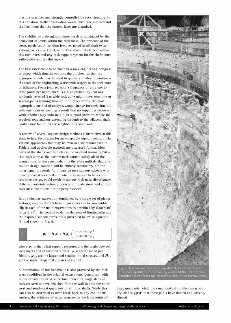
The stability of a strong and dense basalt is dominated by the
behaviour of joints within the rock mass. The presence of the
steep, north–south trending joint set noted in all shaft exca-
vations, as seen in Fig. 4, is the key structural element within
this rock mass and any rock support system for the shafts must
sufficiently address this aspect.
The first assessment to be made in a rock engineering design is
to assess which domain controls the problem, so that the
appropriate tools may be used to quantify it. Most important is
the scale of the engineering works with respect to the rock zone
of influence. For a joint set with a frequency of only one to
three joints per metre, there is a high probability that any
randomly selected 3 m wide rock zone might have zero, one or
several joints running through it. In other words, the most
appropriate method of analysis would change for each situation
with one analysis yielding a result that no support is necessary
while another may indicate a high support pressure, where the
required rock anchors extending through to the adjacent shaft
could cause failure on the neighbouring shaft wall.
A review of several support design methods is instructive at this
stage to help focus ideas for an acceptable support solution. The
various approaches that may be reviewed are summarised in
Table 1 and applicable methods are discussed further. Most
parts of the shafts and tunnels can be assessed normally but a
thin rock zone at the narrow neck cannot satisfy all of the
assumptions in these methods. It is therefore unlikely that any
routine design solution will be entirely satisfactory. On the
other hand, proposals for a massive rock support scheme with
heavily loaded rock bolts, in what may appear to be a con-
servative design, could result in serious rock mass disturbances
if the support–interaction process is not understood and current
rock mass conditions not properly assessed.
In any circular excavation dominated by a single set of planar
features, such as the IPS basalt, two zones can be susceptible to
slip in each of the main excavations as described by Goodman6
(after Bray7). The method to define the zone of limiting-slip and
the required support pressures is presented below in equation
(1) and shown in Fig. 5.
pb ¼ ðN1p1 þ N2p2Þ1 � cot a tanfj
1 þ tan a tanfj
!1
where pb is the radial support pressure, a is the angle between
rock layers and excavation surface, fj is the angle of joint
friction, p1;2 are the larger and smaller initial stresses, and N1;2
are the initial tangential stresses at a point.
Substantiation of this behaviour is also provided by the rock
mass conditions in the original excavations. Concurrent with
initial excavation or at some time thereafter, large slabs of
rock are seen to have detached from the wall in both the north–
west and south–east quadrants of all three shafts. While this
can also be described as over-break back to any continuous
surface, the evidence of water seepages in the large joints of
these quadrants, while the same joint set in other areas are
dry, also suggests that these joints have dilated and possibly
slipped.
Fig. 4. The narrow neck in pump shaft 1, before excavation.(The poor quality of the retaining walls and the near vertical,persistent joint traces can be clearly seen in the narrow neck)
4 Geotechnical Engineering 149 Issue 3 Widening and deepening large shafts in rock Antonio 0 Adams
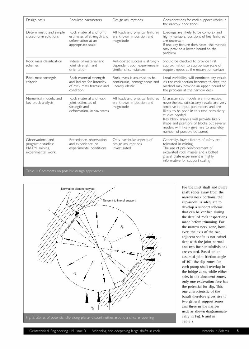
For the inlet shaft and pump
shaft zones away from the
narrow neck portions, the
slip-model is adequate to
develop a support scheme
that can be verified during
the detailed rock inspections
made before trimming. For
the narrow neck zone, how-
ever, the axis of the two
adjacent shafts is not coinci-
dent with the joint normal
and two further subdivisions
are created. Based on an
assumed joint friction angle
of 308, the slip zones for
each pump shaft overlap in
the bridge zone, while either
side, in the abutment zones,
only one excavation face has
the potential for slip. This
one characteristic of the
basalt therefore gives rise to
two general support zones
and three in the narrow
neck as shown diagrammati-
cally in Fig. 6 and in
Table 2.
Design basis Required parameters Design assumptions Considerations for rock support works inthe narrow neck zone
Deterministic and simpleclosed-form solutions
Rock material and jointestimates of strength anddeformation at anappropriate scale
All loads and physical featuresare known in position andmagnitude
Loadings are likely to be complex andhighly variable, positions of key featuresare uncertainIf one key feature dominates, the methodmay provide a lower bound to theproblem
Rock mass classificationschemes
Indices of material andjoint strength andorientation
Anticipated success is stronglydependent upon experience insimilar circumstances
Should be checked to provide firstapproximation to appropriate scale ofsupport needs at the excavation surface
Rock mass strengthcriteria
Rock material strengthand indices for intensityof rock mass fracture andcondition
Rock mass is assumed to becontinuous, homogeneous andlinearly elastic
Local variability will dominate any resultAs the rock section becomes thicker, themethod may provide an upper bound tothe problem at the narrow deck
Numerical models, andkey block analysis
Rock material and rockjoint estimates ofstrength anddeformation, in situ stress
All loads and physical featuresare known in position andmagnitude
Characteristic models are informative,nevertheless, satisfactory results are verysensitive to input parameters and arelikely to be poor in this case, sensitivitystudies neededKey block analysis will provide likelyshape and positions of blocks but severalmodels will likely give rise to unwieldynumber of possible outcomes
Observational andpragmatic studies:NATM, mining,experimental work
Precedence, observationand experience, or,experimental conditions
Only particular aspects ofdesign assumptionsinvestigated
Generally, lower factors of safety aretolerated in miningThe use of pre-reinforcement ofexcavated rock masses and a boltedgravel plate experiment is highlyinformative for support scaling
Table 1. Comments on possible design approaches
Normal to discontinuity set
Tangent to line of support
Pb
Pb
P2
P1
Zone
of p
oten
tial s
lip
Zone
of p
oten
tial s
lip
2φ
θ
α
Fig. 5. Zones of potential slip along planar discontinuities around a circular opening
Geotechnical Engineering 149 Issue 3 Widening and deepening large shafts in rock Antonio 0 Adams 5
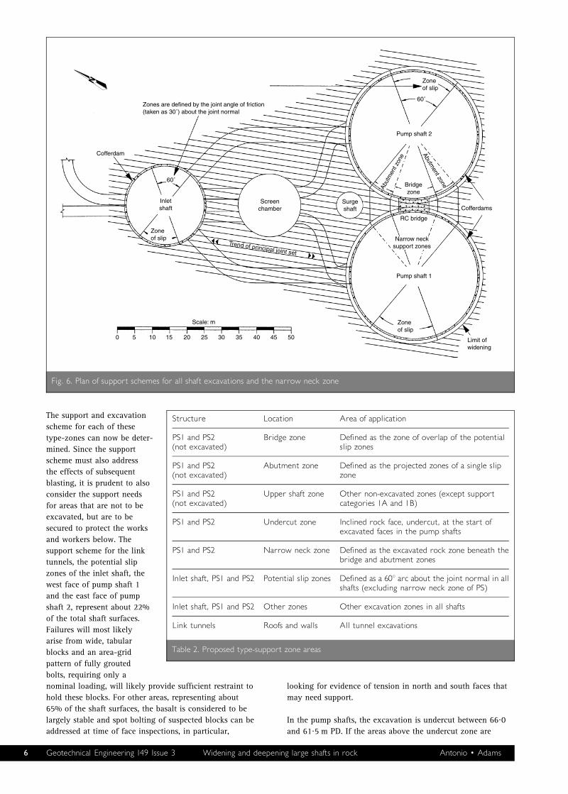
The support and excavation
scheme for each of these
type-zones can now be deter-
mined. Since the support
scheme must also address
the effects of subsequent
blasting, it is prudent to also
consider the support needs
for areas that are not to be
excavated, but are to be
secured to protect the works
and workers below. The
support scheme for the link
tunnels, the potential slip
zones of the inlet shaft, the
west face of pump shaft 1
and the east face of pump
shaft 2, represent about 22%
of the total shaft surfaces.
Failures will most likely
arise from wide, tabular
blocks and an area-grid
pattern of fully grouted
bolts, requiring only a
nominal loading, will likely provide sufficient restraint to
hold these blocks. For other areas, representing about
65% of the shaft surfaces, the basalt is considered to be
largely stable and spot bolting of suspected blocks can be
addressed at time of face inspections, in particular,
looking for evidence of tension in north and south faces that
may need support.
In the pump shafts, the excavation is undercut between 66?0
and 61?5 m PD. If the areas above the undercut zone are
0 5 10 15 20 25 30 35 40 45 50
Scale: m
Zones are defined by the joint angle of friction(taken as 30˚) about the joint normal
Cofferdam
Inletshaft
Screenchamber
Surgeshaft
Zoneof slip
Zoneof slip
Zoneof slip
60˚
60˚
Trend of principal joint set
Pump shaft 2
Pump shaft 1
Cofferdams
Bridgezone
RC bridge
Narrow necksupport zones
Abut
men
t zon
e
Abutment zone
Limit ofwidening
Fig. 6. Plan of support schemes for all shaft excavations and the narrow neck zone
Structure Location Area of application
PS1 and PS2(not excavated)
Bridge zone Defined as the zone of overlap of the potentialslip zones
PS1 and PS2(not excavated)
Abutment zone Defined as the projected zones of a single slipzone
PS1 and PS2(not excavated)
Upper shaft zone Other non-excavated zones (except supportcategories 1A and 1B)
PS1 and PS2 Undercut zone Inclined rock face, undercut, at the start ofexcavated faces in the pump shafts
PS1 and PS2 Narrow neck zone Defined as the excavated rock zone beneath thebridge and abutment zones
Inlet shaft, PS1 and PS2 Potential slip zones Defined as a 608 arc about the joint normal in allshafts (excluding narrow neck zone of PS)
Inlet shaft, PS1 and PS2 Other zones Other excavation zones in all shafts
Link tunnels Roofs and walls All tunnel excavations
Table 2. Proposed type-support zone areas
6 Geotechnical Engineering 149 Issue 3 Widening and deepening large shafts in rock Antonio 0 Adams
secured, the support may be considered as a tunnel roof and an
appropriate support scheme is devised accordingly from rock
mass schemes. The recommended support measures include
shotcrete and wire mesh to tie the surface and the convex
corner to the upper shaft areas. Also, the upper pump shaft
zones which are not to be excavated may require additional
support to minimise blasting disturbance and to secure the
foundations of the retaining walls above. Support for these
areas include bolting, grouting and shotcrete to provide a
secure surface around the entire periphery of all the shafts. Full
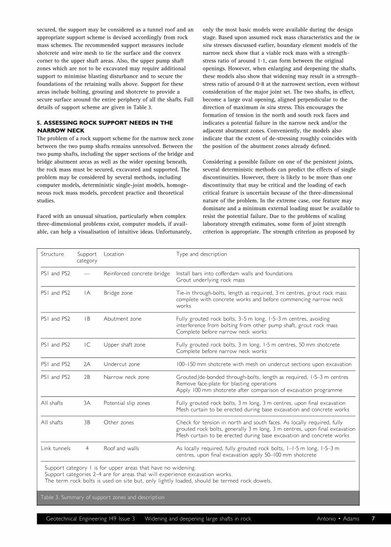
details of support scheme are given in Table 3.
5. ASSESSING ROCK SUPPORTNEEDS IN THENARROWNECKThe problem of a rock support scheme for the narrow neck zone
between the two pump shafts remains unresolved. Between the
two pump shafts, including the upper sections of the bridge and
bridge abutment areas as well as the wider opening beneath,
the rock mass must be secured, excavated and supported. The
problem may be considered by several methods, including
computer models, deterministic single-joint models, homoge-
neous rock mass models, precedent practice and theoretical
studies.
Faced with an unusual situation, particularly when complex
three-dimensional problems exist, computer models, if avail-
able, can help a visualisation of intuitive ideas. Unfortunately,
only the most basic models were available during the design
stage. Based upon assumed rock mass characteristics and the in
situ stresses discussed earlier, boundary element models of the
narrow neck show that a viable rock mass with a strength–
stress ratio of around 1?1, can form between the original
openings. However, when enlarging and deepening the shafts,
these models also show that widening may result in a strength–
stress ratio of around 0?8 at the narrowest section, even without
consideration of the major joint set. The two shafts, in effect,
become a large oval opening, aligned perpendicular to the
direction of maximum in situ stress. This encourages the
formation of tension in the north and south rock faces and
indicates a potential failure in the narrow neck and/or the
adjacent abutment zones. Conveniently, the models also
indicate that the extent of de-stressing roughly coincides with
the position of the abutment zones already defined.
Considering a possible failure on one of the persistent joints,
several deterministic methods can predict the effects of single
discontinuities. However, there is likely to be more than one
discontinuity that may be critical and the loading of each
critical feature is uncertain because of the three-dimensional
nature of the problem. In the extreme case, one feature may
dominate and a minimum external loading must be available to
resist the potential failure. Due to the problems of scaling
laboratory strength estimates, some form of joint strength
criterion is appropriate. The strength criterion as proposed by
Structure Supportcategory
Location Type and description
PS1 and PS2 D Reinforced concrete bridge Install bars into cofferdam walls and foundationsGrout underlying rock mass
PS1 and PS2 1A Bridge zone Tie-in through-bolts, length as required, 3 m centres, grout rock masscomplete with concrete works and before commencing narrow neckworks
PS1 and PS2 1B Abutment zone Fully grouted rock bolts, 3^5 m long, 1?5^3 m centres, avoidinginterference from bolting from other pump shaft, grout rock massComplete before narrow neck works
PS1 and PS2 1C Upper shaft zone Fully grouted rock bolts, 3 m long, 1?5 m centres, 50 mm shotcreteComplete before narrow neck works
PS1 and PS2 2A Undercut zone 100^150 mm shotcrete with mesh on undercut sections upon excavation
PS1 and PS2 2B Narrow neck zone Grouted/de-bonded through-bolts, length as required, 1?5^3 m centresRemove face-plate for blasting operationsApply 100 mm shotcrete after comparison of excavation programme
All shafts 3A Potential slip zones Fully grouted rock bolts, 3 m long, 3 m centres, upon final excavationMesh curtain to be erected during base excavation and concrete works
All shafts 3B Other zones Check for tension in north and south faces. As locally required, fullygrouted rock bolts, generally 3 m long, 3 m centres, upon final excavationMesh curtain to be erected during base excavation and concrete works
Link tunnels 4 Roof and walls As locally required, fully grouted rock bolts, 1^1?5 m long, 1?5^3 mcentres, upon final excavation apply 50^100 mm shotcrete
Support category 1 is for upper areas that have no widening.Support categories 2^4 are for areas that will experience excavation works.The term rock bolts is used on site but, only lightly loaded, should be termed rock dowels.
Table 3. Summary of support zones and description
Geotechnical Engineering 149 Issue 3 Widening and deepening large shafts in rock Antonio 0 Adams 7
Barton and Bandis,8 with the currently available rock mass data
and low stress levels, is ideally suited to this situation. In a
simple two-dimensional model, assume that before excavation
a through-going discontinuity with an angle of friction of 308and JRC value of 5 exists at a critical angle of 608, then the
shear strength may be estimated using the Barton joint strength
model, as
tt ¼ ssn tan fb þ JRC log10
ssj
ssn
� �2
where tt is the joint shear strength, JRC is the joint roughness
coefficient, ssn is the normal stress on the joint, fb is the joint
basic angle of friction, and ssj is the joint compressive strength.
In this case, the narrow neck is found to be stable. But, after
excavation, the upper rock zone is not thinned and so the
vertical loading on the interior remnant of the same existing
joint may be increased by around 60% since the much smaller
shearing surface is only partially compensated by a reduced
weight of overlying rock. Excluding any other external forces,
this calculation provides factors of safety of 0?99 before, and
0?94 after excavation and although the actual values of these
factors of safety are not important at this stage, the calculation
shows that any critically orientated through-going joint would
already be close to a factor of safety of 1.
The other extreme to a single critical joint is to consider that
the rock volume in the narrow neck is large enough to be
considered a homogeneous rock mass. It should be noted that
designers must apply caution when using such schemes in
respect of an assumed continuous nature of rock masses (most
particularly, for transversely isotropic masses with through-
going discontinuities) and the situation at the narrow neck
should, ordinarily, be discounted on this basis. However, a
rapid assessment can be useful, particularly as the method does
become more applicable the further one moves into the abut-
ment zones where a check on the bearing capacity is required
for the support available for a natural rock arch. The generalised
strength criterion proposed by Hoek et al.9 is as follows
ss01 ¼ ss03 þ ssci mbss03ssci
þ s
� �a
3
where ss01;3 is the effective axial and confining stress; mb, s and
a are rock mass constants (from GSI values); and ssci is the
intact rock material strength.
From rock mass classification data, the complete stress–strain
curve and the uniaxial rock mass strength may be estimated.
Using a geological strength index (GSI) value of 55, mi of 17
and an intact material strength of 100 MPa, gives a rock mass
uniaxial strength, sscm, of around 13 MPa, using
sscm ¼ 2c cosf1 � sinf4
where sscm is the rock mass uniaxial strength, c is the rock mass
cohesion, and f is the rock mass angle of friction.
Clearly, an intact rock mass could safely support the new
uniaxial loading of around 1 MPa at the narrow neck, if the
effects of the major discontinuities are ignored. Equally, the
abutment zones can provide sufficient reaction to a natural
rock arch.
Lang10 has experimented with gravel plate models in develop-
ing rules for critical rock bolt spacings and the results are
particularly relevant here since a thin, discontinuous ‘gravel’
layer used in the experiments is analogous to the discontinuous
rock mass that exists between the pump shafts. The conclusions
of these experiments do give some reassurance that a thin rock
wall can be a viable structural element if properly designed.
The mining industry also has many examples of working close
to the limits of the ultimate strength of rock masses. Indeed,
some mining techniques demand the controlled failure of a
rock mass to operate efficiently, or, routinely rely upon thin
rock walls for hanging wall support. Despite these analogies, it
is difficult to apply mining techniques in this situation since
they are frequently operated with lower factors of safety than
normally required in civil engineering and the consequences
associated with failure are much greater. Similarly, NATM or
other observational methods of construction may not be
reliable because the interpretation of deformation trends of an
already disturbed rock mass may be an impossible task. NATM
requires a known performance model to compare actual
deformations. In a small rock volume, locating or detecting the
one point that may indicate impending rock failure may not be
possible at all. Nevertheless, if failure did occur, it could
possibly be both rapid and catastrophic from one or several
blocks in either shaft and giving little time to react with
appropriate countermeasures.
In summary then, the review may appear to be pessimistic,
since all of the methods examined only give a series of
limitations to their use. Very simplistic design methods have
shown that the rock mass would probably fail without restraint.
A picture emerges that shows the rock mass to be of a good
quality (ignoring the persistent joints), but more importantly,
there are indications that parts of the rock mass may already be
in a post-failure condition. The joints are relatively strong, but
their shear strength must be maximised to maintain the current
levels of stability with an anticipated increased load and still
allow other activities to continue within the shafts. Rock
support must, therefore, aim to limit joint dilation while
ensuring an adequate face stability. Since there are indications
that the rock mass could already be in a post-failure condition,
the support should be stiff, but largely passive and should not
load the surface, because the consequences of an active loading
on this system are unpredictable.
6. THENARROWNECK ROCK SUPPORT SCHEMEThe cast-in-place concrete beam between the cofferdams (as
shown during construction in Fig. 7) will encourage the
formation of a natural rock arch through the completed upper
shaft zone. Further reinforcement and grouting of the under-
lying rock would improve rock continuity and even if
subsequent works cause a rock failure below, the cofferdams
will be secured. Nevertheless, for safety reasons, the rock
beneath the arch still requires support as well, but it is difficult
to predict the behaviour of this zone during and after
excavation.
8 Geotechnical Engineering 149 Issue 3 Widening and deepening large shafts in rock Antonio 0 Adams
A grid of through-going cables was originally proposed,
subsequently modified to bars, to constrain the narrow neck
and limit any further joint dilation, as shown in Fig. 8. The
spacings of through-bolts can be determined as half the narrow
neck thickness at 1?5 m rising to 3 m away from the middle, but
not greater than four times the mean joint spacing, that is, less
than 4 m. The 1?5 m spacing, not surprisingly, also satisfies the
recommendations of both Rock Mass Quality Index (Q) and
Rock Mass Rating Index (RMR) systems for surface rock
support. A 30 mm deformed steel bar was proposed, placed in
oversized holes to ease installation and allow a free flow of
grout. Grout was a high water–cement ratio mix (0?35–0?40) to
flow freely into any voids and provide an expected compressive
strength of at least 20 MPa.
The pre-installation of support provides a passive system,
designed to limit rock mass dilation as much as possible and is
also sufficiently robust so as not to be damaged by blasting.
The bars were painted with a thick bituminous paint in portions
to be excavated to discourage any hard contact with grout. The
face-plates were installed to allow a nominal straightening load
and the hole was then grouted. During excavation, at any level,
the face-plates were temporarily removed to allow rock to freely
detach around the bars. Following the blast and a face inspection,
the face-plates were replaced to the new rock surface. This
scheme provides support by maintaining the pre-blasting loads
on the interior of the rock mass. As the excavation progressed,
the tendency of any area to fail was restrained in equal measure
by the presence of passive through-bolts acting in the central
portion of the narrow neck. Monitoring was completed at each
stage and no progressive movements were seen.
The reinforced concrete beam tied into bedrock and into the
cofferdams. A rock grouting programme ensured a solid
structure over the narrowest section of rock wall. In the upper
parts of the bridge zone, where the shafts do not require
widening, the through-bolts could be entirely grouted. In the
ever-widening arch of the abutment zone, long, fully grouted
rock bolts were fixed into the rock mass to resist sliding and
provide a stable foundation for a natural rock arch and
including the bridge structure and retaining walls.
In summary, a systematic, staged support and excavation
scheme is required, which is simple to construct and at least
maintains the current safety levels. The scheme must be
developed and scaled so it can provide for safe working before,
during and after excavation, until the excavations are deepened
and lined. The adopted support scheme was a system of
through-bolts of pre-reinforcement, which could maintain the
existing loading in the interior of the rock while blasting
operations continued around the support elements.
7. ASSESSING ANEXCAVATIONMETHODOLOGYThe excavation tasks include the removal of the existing
reinforced concrete rafts at the base of both pump shafts, the
deepening of the pump shafts and rock trimming in all shafts.
The trimming of the rock on both sides of the narrow neck gave
most concern.
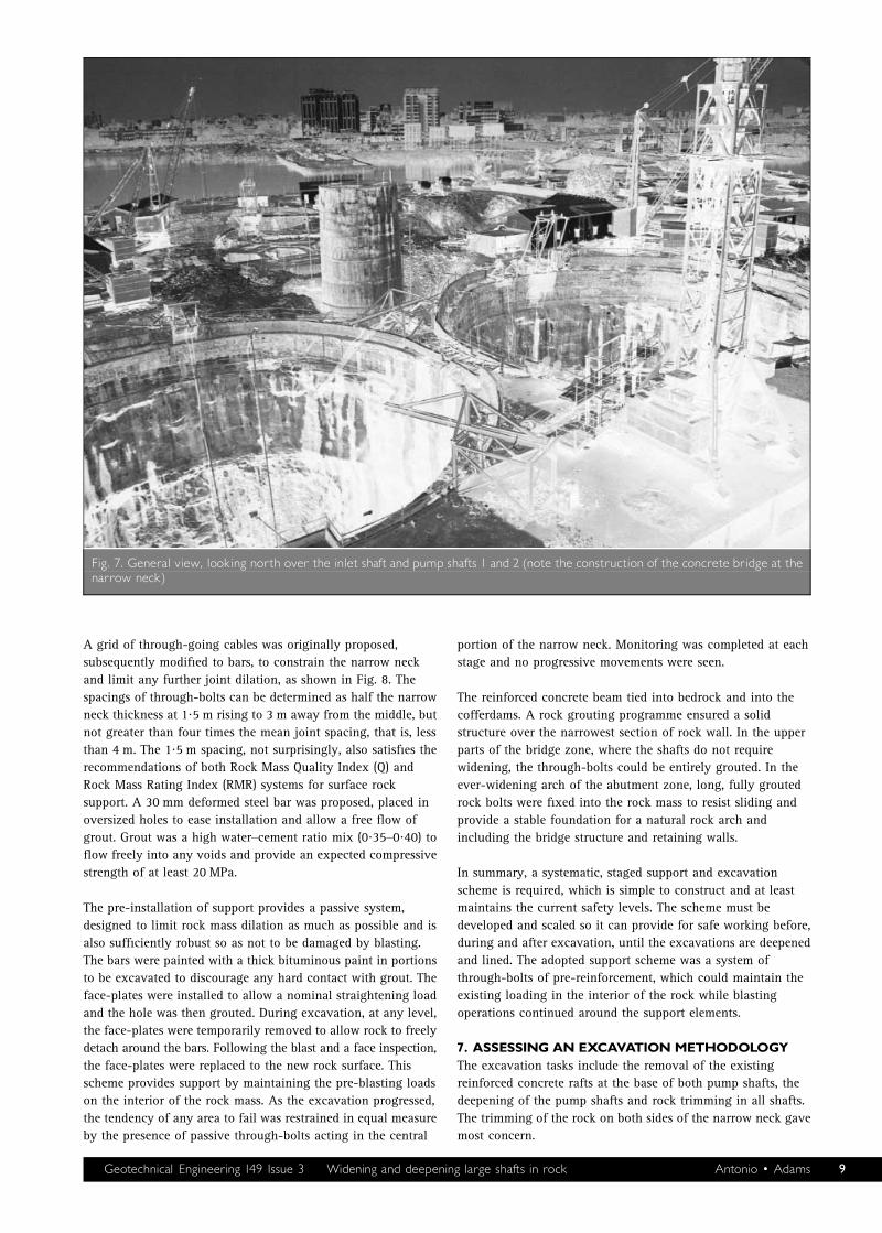
Fig. 7. General view, looking north over the inlet shaft and pump shafts 1 and 2 (note the construction of the concrete bridge at thenarrow neck)
Geotechnical Engineering 149 Issue 3 Widening and deepening large shafts in rock Antonio 0 Adams 9
Generally, for the areas away from the narrow neck, the
perimeter blasting of the shafts was excavated in a series of
12 m wide panels of two rows of 20 radial blast holes at
600 mm centres. Horizontal holes were drilled to the required
clearance depth with charge weights of 0?22 kg/m used with
nine delays, firing four holes a time. The resultant peak particle
velocities were generally less than 5 mm/s. In the 16 m zone
either side of the narrowest part of the narrow neck, charge
weights were halved and only 6 m panels were used. The
spacings, simultaneous charge and charge weights of each blast
were adjusted locally to suit actual profile requirements. Each
panel comprised two rows of ten holes at 600 mm centres. Each
row was fired by stepping around the shaft perimeter, firing
lower rows first, then the upper row of the previous panel.
The existing pump shaft bases each comprise a massive 2?2 m
thick of reinforced concrete, each containing some 2500 m3
of concrete and 400 t of steel. Drilling and blasting this
structure is a difficult task, inevitably producing high wear
for equipment designed for rock blasting. The slab was divided
into sectors, allowing effective blast designs to be exploited.
Inspections were completed after each blast and concurrent face
and shaft base works were permitted, although all shafts were
cleared for the routine late-afternoon blasts.
8. EXECUTIONAND PROGRESSSite mobilisation, de-watering, access, surveying and logging
took place between April and December 1996. All temporary
support (including shotcrete, grouting and bolting) and the
construction of the concrete beam followed up to March
1997.
Between January 1996 and February 1997, raft-breaking
(5000 cubic metres), enlargement (9200 m3) and deepening
(22 100 m3) took place. Blasting each day at two or three
locations, the concrete rafts required 400 blasts and yielded
some 12 m3 per blast, enlargement yielded 28 cubic metres per
blast and deepening some 62 m3 per blast. Typically four to six
blasts were taken each day and included inspection, barring
down and any additional temporary support installation. Fig. 9
gives a view from the base of pump shaft 1 and provides a
good impression of the scale of the works.
Work commenced on civil construction in February 1998 and is
expected to be complete by June 2001.
9. DISCUSSIONAND CONCLUSIONSIt is the case in many projects around the world that local
contractors are less experienced (or indeed confident) in the
latest techniques of rock engineering and it is important that a
team effort provides a consensus between designer and builder.
It is, therefore, a necessary requirement that the proposed
methods give confidence, by adopting the simplest schemes
that can be built. For the Bandra project, in the development of
type-zones for rock support, the on-site capabilities were
recognised and frequent discussions enabled a consensus on
After blasting 50–100 mm thickshotcrete layer
Blast holes
Face plates aretemporarily removed
during blastingand replacedon new face
Debondedportion
Cementgroutedportion
0 1 2 3 4 5 6 7 8 9 10
Scale: m
Existingexcavation33·0 m dia.
Enlarged excavation37·0 m dia.
Narrowneck
Undercut zone
(Grouted above undercut)
Bridge and abutmentzones of narrow neck
61·50 m
66·00 m
74·00 m
79·00 m
Through boltsgrouted/debondedat 1–5 m centres
Through boltsfully groutedat 1–5 m centres
100–150 mm thickshotcrete layer
Cofferdam walls
Reinforced concrete beam, 10·4 m long tied in tocofferdam walls with 24 No. 25 mm dia. steel dowels
Pumpshaft 2
Pumpshaft 1
Fig. 8. Section through narrow neck and support detail
10 Geotechnical Engineering 149 Issue 3 Widening and deepening large shafts in rock Antonio 0 Adams
methods and materials to be
agreed. For the excavation of
the pump shafts, some
through-bolts were replaced
with bars installed only to the
boundary of the excavation
zone in the other shaft, that
is, not completely through the
rock. The remaining empty
hole was blocked with timber.
This practical modification
was a little easier to use,
although it was not possible
to re-tension any bars after
blasting.
The situation that led to reas-
sessment of the design of
rock support and the design
of the pump shaft excava-
tions arose because of a series
of quite reasonable but
unfortunate assumptions
concerning the condition of a
previously occupied site. Due
regard was given to what
was readily available in
terms of materials and equip-
ment, for installing the tem-
porary support by the
contractor.
The support scheme adopted
was, necessarily, innovative
and had to be rapidly devel-
oped prior to excavation.
Basic theoretical rules were
followed and although many
parameters could not be
established with real confi-
dence, useful schemes and
guidelines were produced that
helped determine both the
type and scale of support. The
size of the rock mass in the
most critical zone of the
narrow neck, was a larger
volume than appropriate to
use material or single joint
analyses and, conversely, was
a smaller volume than could be reliably described as a
homogeneous rock mass. A wide spectrum of analyses had to
be reviewed and any guidelines taken from them to apply a
sensible support scheme that was not in conflict with any single
approach.
At Bandra IPS, a good-quality basalt rock mass could not be
used as an integral part of the station structure and was the
source of many problems and concerns when the basalt rock
mass was excavated during the narrow neck widening. On a
virgin site, other criteria could have led to a different design
and layout for the pump station.
As a foundation material, a uniform, compact basalt is one of
the best available. It is widely used as a construction material
with a massive bearing capacity and a largely predictable
performance. Overall, it could be argued that the rock
excavated to allow the construction of concrete walls may have
been as good, if not better, in strength and deformation
characteristics than the concrete that replaced it. The weakness
of this argument at Bandra IPS, was that the rock contained
obvious discontinuities that, for very high loading structures,
could lead to some degree of anisotropic elastic response and,
consequently, adverse bending moments in any structure built
within it. However, these poorer characteristics are relatively
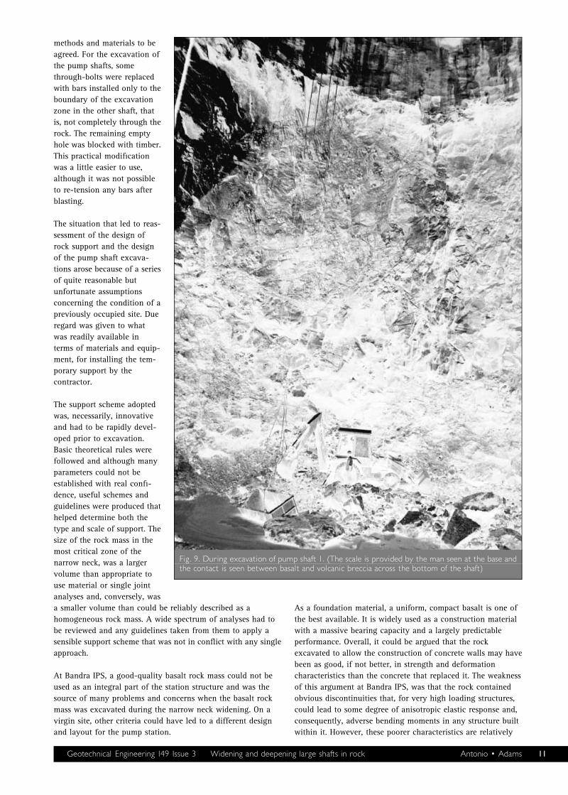
Fig. 9. During excavation of pump shaft 1. (The scale is provided by the man seen at the base andthe contact is seen between basalt and volcanic breccia across the bottom of the shaft)
Geotechnical Engineering 149 Issue 3 Widening and deepening large shafts in rock Antonio 0 Adams 11
straightforward to resolve with either bolting or grouting being
used to even out this anisotropic character.
Watertightness is a necessity for a structure designed to contain
sewage and exclude groundwater. The resulting buoyancy of a
watertight structure is largely resisted by self-weight in the
current station design. However, in a structure with less rock
excavation, that is, with thinner internal lining walls, tension
anchors connected into the base slab and the lower wall
sections would probably be required to resolve these concerns.
None of these options could be used because of the constraints
imposed by the existing site layout and the advanced civil,
mechanical and electrical contracts. Although the present
design is a highly effective station, similar situations could
employ a simpler construction with a more effective use of the
site geology. As in many underground structures, using the
surrounding rock mass to form an integral structural element
may provide useful cost benefits. Working in a good-quality
rock, such as that at Bandra IPS, should be seen as a freely
available resource and an opportunity to be exploited.
10. ACKNOWLEDGEMENTSThe authors wish to acknowledge and congratulate the
engineer, Mr D. Kell, the project manager Mr A. Beattie and
staff of Binnie Black & Veatch and Tata Consulting Engineers,
the Municipal Corporation of Mumbai and the staff of Hindu-
stan Construction Company on the successful completion of the
work described in this paper.
Particular thanks are offered to the original engineer for the
works, Mr N. Dawes (previous partner of Binnie & Partners,
UK). His positive support and clear direction during the difficult
period at the start of the works, is gratefully acknowledged.
11. REFERENCES1. POWAR K. B. Evolution of the Deccan Province. Proceedings
of the 74th Indian Science Congress, Bangalore, Part II:
Presidental Address, 1987, pp. 1–30.
2. AVASIA R. K. and GANGOPADHAYAY M. Distribution of
secondary minerals in the Western Deccan Traps of
Bombay–Baroda coastal tract, India. Indian Mineralogist,
1984, 215–230.
3. BARTON N. R., LIEN R. and LUNDE J. Engineering classifica-
tion of rock masses for the design of tunnel support. Rock
Mechanics, 1974, 6, No. 4, 189–239.
4. BIENIAWSKI Z. T. Engineering Rock Mass Classifications.
Wiley, New York, 1989.
5. ANTONIO E. C. The identification, effects and control of weak
sub-horizontal discontinuities in a TBM excavated tunnel
(in preparation).
6. GOODMAN R. E. Introduction to Rock Mechanics. Wiley, New
York, 1980.
7. BRAY J. A study of jointed and fractured rock-part II.
Felsmechanik und Ingenieurgeologie, 1967, V, No. 4,
197–216.
8. BARTON N. R. and BANDIS S. C. Review of predictive
capabilities of JRC–JCS model in engineering practice.
Proceedings of an International Symposium on Rock Joints,
Loen, Norway (Barton N. and Stephansson O. (eds)).
Balkema, Rotterdam, 1990, pp. 603–610.
9. HOEK E., KAISER P. K. and BAWDEN W. F. Support of Under-
ground Excavations in Hard Rock. Balkema, Rotterdam, 1995.
10. LANG T. A. Theory and practice of rockbolting. Transactions
of the American Institute of Engineers, 1961, 220, 333–348.
Please email, fax or post your discussion contributions to the secretary: email: [email protected]; fax: +44 (0)20 7799 1325; orpost to Lesley Wilson, Journals Department, Institution of Civil Engineers, 1^7 Great George Street, London SW1P 3AA.
12 Geotechnical Engineering 149 Issue 3 Widening and deepening large shafts in rock Antonio 0 Adams


