Embed Size (px)
Citation preview
Geodetic & Geospatial Infrastructure/Systems
1. Geodetic System: Borneo Triangulation 1968 (BT68)
2. Geospatial System: Land and Survey Information System (LASIS)
An Agency to Facilitate Development LAND AND SURVEY DEPARTMENT SARAWAK
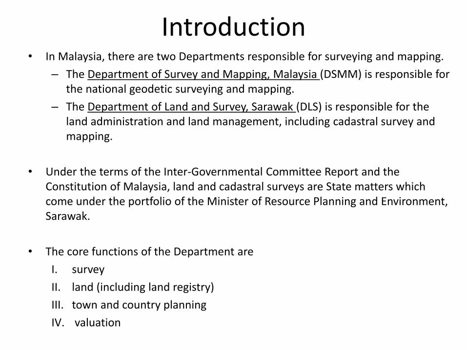
Introduction • In Malaysia, there are two Departments responsible for surveying and mapping.
– The Department of Survey and Mapping, Malaysia (DSMM) is responsible for the national geodetic surveying and mapping.
– The Department of Land and Survey, Sarawak (DLS) is responsible for the land administration and land management, including cadastral survey and mapping.
• Under the terms of the Inter-Governmental Committee Report and the Constitution of Malaysia, land and cadastral surveys are State matters which come under the portfolio of the Minister of Resource Planning and Environment, Sarawak.
• The core functions of the Department are
I. survey
II. land (including land registry)
III. town and country planning
IV. valuation
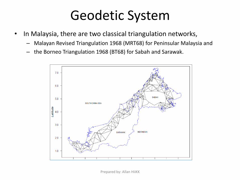
Geodetic System • In Malaysia, there are two classical triangulation networks,
– Malayan Revised Triangulation 1968 (MRT68) for Peninsular Malaysia and
– the Borneo Triangulation 1968 (BT68) for Sabah and Sarawak.
Prepared by: Allan HiiKK
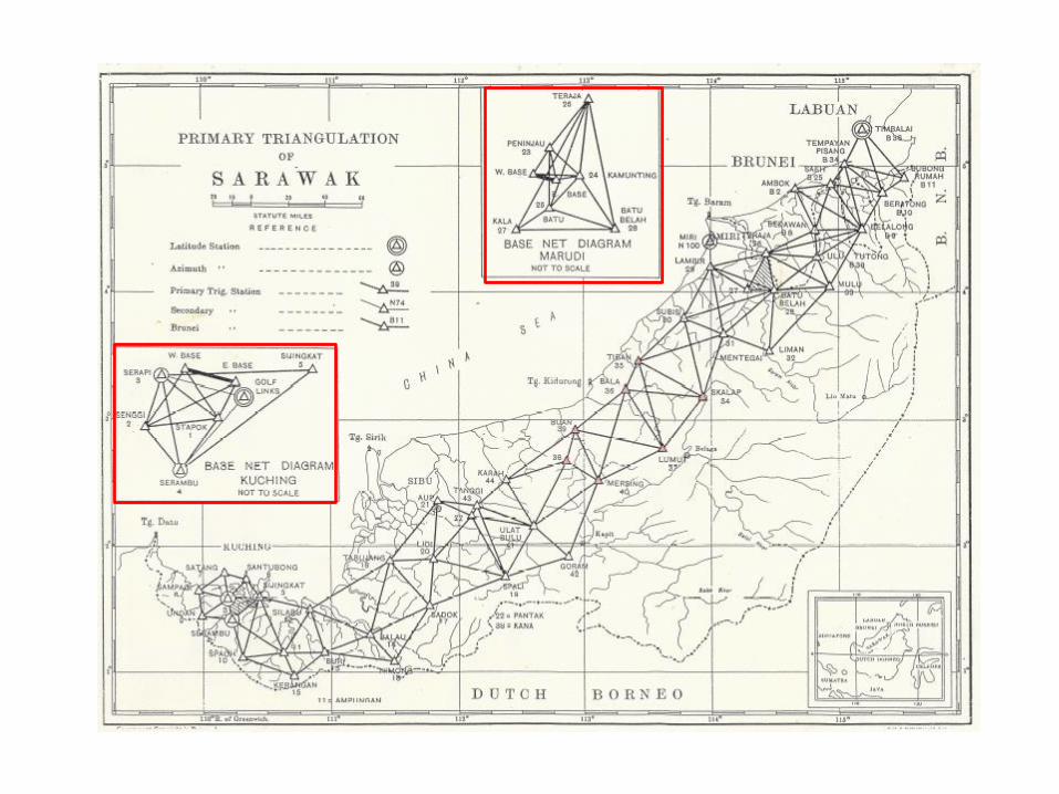
Primary Triangulation of Sarawak • 1925: Survey framework in Sarawak was technically non-existent; a
network of minor triangulation near Kuching with scattered astro-fixes and of a few traverses – reconnaissance value only
• 1931: The government decided to establish a framework of triangulation with following limits of error: Angular: not more than 1” per angle with maximum of 3” per triangle; Linear: 1 in 25,000 between bases.
• First base-line was established at Kuching. Astro observations for latitude and longitude were carried out at Golf Link, Kuching & azimuth was observed at Serapi. Adopted as the datum for the western portion of the triangulation: Matang Base.
• 1934: Cooperated with the Survey of Brunei to establish 2nd Sarawak base line near Marudi, Miri or Marudi Base. Latitude & longitude were measured at Labuan and azimuth was observed at Timbalai.
• The Triangulation of Brunei, is based on astronomical observations at Labuan and was computed in terms of Marudi Base.
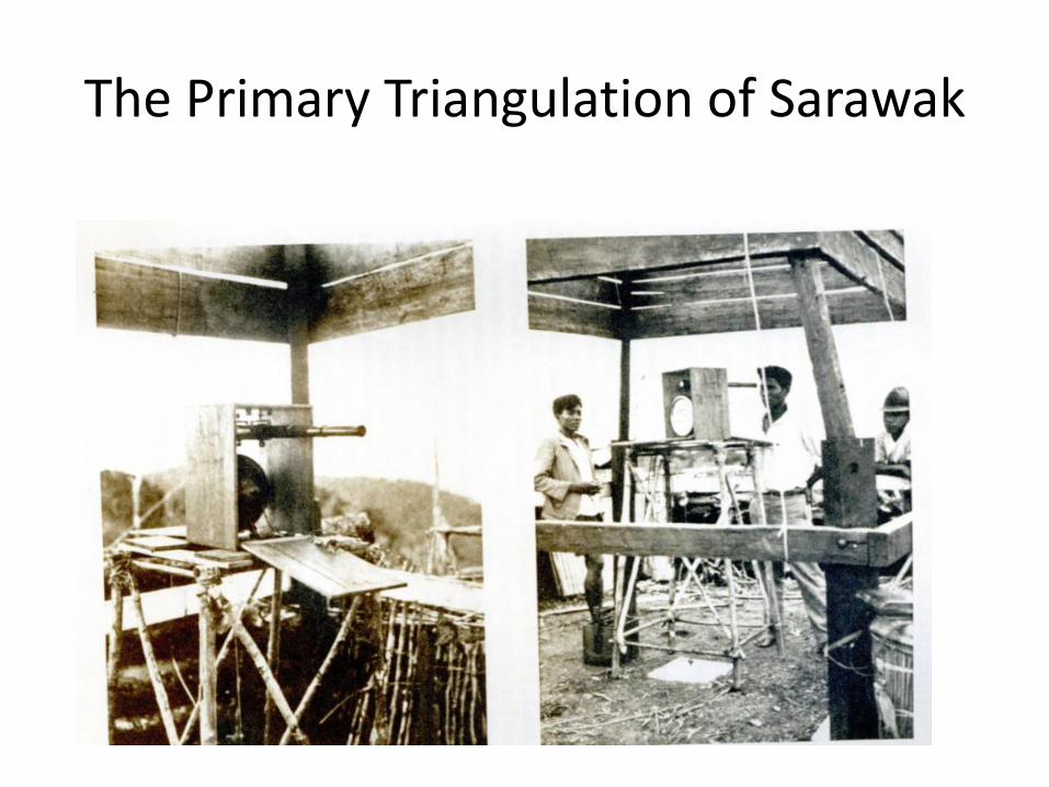
The Primary Triangulation of Sarawak
Review of existing Infrastructure – BORNEO TRIANGULATION 1968 (BT68)
• Sabah started its primary triangulation work in a project known as the Borneo West Coast Triangulation between 1930 and 1942. Around 1935, Sarawak and Brunei also began their primary triangulation projects.
• The Directorate of Overseas Survey (DOS) undertook the task of readjusting the whole primary triangulation of Borneo.
• The adjusted results for the Primary Triangulation of Borneo 1948 were then published in terms of Timbalai Datum and Modified Everest Ellipsoid.
• The East Coast Triangulation was later introduced and initiated by DOS and observations were carried out in the year 1955 to 1960. The aim of this triangulation was to extend the Primary Triangulation of Borneo to the eastern side of Sabah. EDM traversing were also carried out from 1961 to 1968 to supplement the work.
• The combined geodetic networks in Sabah, Sarawak and Brunei known as the Borneo Triangulation 1968 (BT68) was established with the origins Bukit Timbalai (in the island of Labuan).
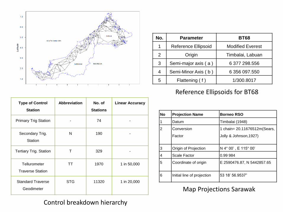
No. Parameter BT68
1 Reference Ellipsoid Modified Everest
2 Origin Timbalai, Labuan
3 Semi-major axis ( a ) 6 377 298.556
4 Semi-Minor Axis ( b ) 6 356 097.550
5 Flattening ( f ) 1/300.8017
Reference Ellipsoids for BT68
No Projection Name Borneo RSO
1 Datum Timbalai (1948)
2 Conversion
Factor
1 chain= 20.11676512m(Sears,
Jolly & Johnson,1927)
3 Origin of Projection N 4° 00’ , E 115° 00’
4 Scale Factor 0.99 984
5 Coordinate of origin E 2590476.87, N 5442857.65
6 Initial line of projection 53 18’ 56.9537”
Control breakdown hierarchy
Type of Control
Station
Abbreviation No. of
Stations
Linear Accuracy
Primary Trig Station - 74 -
Secondary Trig.
Station
N 190 -
Tertiary Trig. Station T 329 -
Tellurometer
Traverse Station
TT 1970 1 in 50,000
Standard Traverse
Geodimeter
STG 11320 1 in 20,000
Map Projections Sarawak
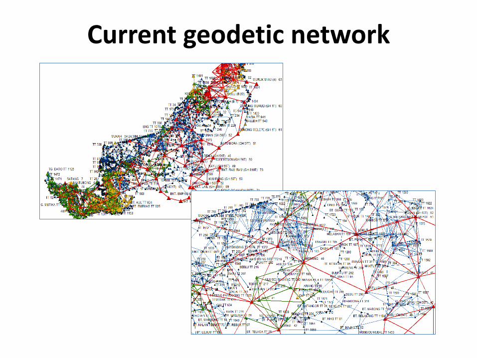
Current geodetic network
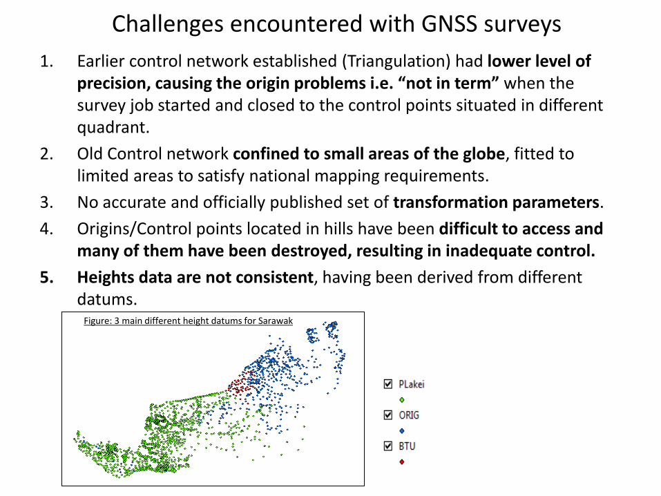
Challenges encountered with GNSS surveys
1. Earlier control network established (Triangulation) had lower level of precision, causing the origin problems i.e. “not in term” when the survey job started and closed to the control points situated in different quadrant.
2. Old Control network confined to small areas of the globe, fitted to limited areas to satisfy national mapping requirements.
3. No accurate and officially published set of transformation parameters.
4. Origins/Control points located in hills have been difficult to access and many of them have been destroyed, resulting in inadequate control.
5. Heights data are not consistent, having been derived from different datums.
Figure: 3 main different height datums for Sarawak
Modernization Roadmap for Cadastral Survey and Mapping
Geodetic Strategic Plan
Project Background
• Modernization Roadmap for Survey and Mapping
• Five days workshop in Kuching, Sarawak from 23 – 27 May 2011, jointly organized by L&S, LSB Sarawak and UTM.
• Attended by 30 land surveyors from the L&S and the private surveyors.
• Five components: Control Infrastructure, datum & projection, DCDB, Height, cadastral survey practices.
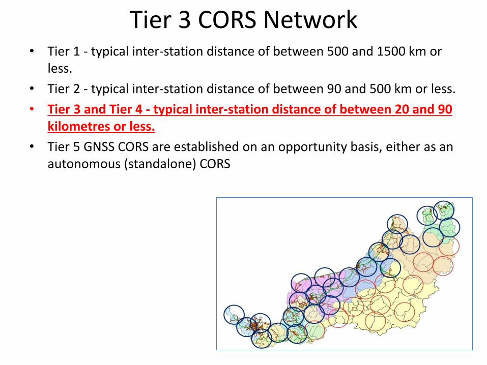
Tier 3 CORS Network • Tier 1 - typical inter-station distance of between 500 and 1500 km or
less.
• Tier 2 - typical inter-station distance of between 90 and 500 km or less.
• Tier 3 and Tier 4 - typical inter-station distance of between 20 and 90 kilometres or less.
• Tier 5 GNSS CORS are established on an opportunity basis, either as an autonomous (standalone) CORS
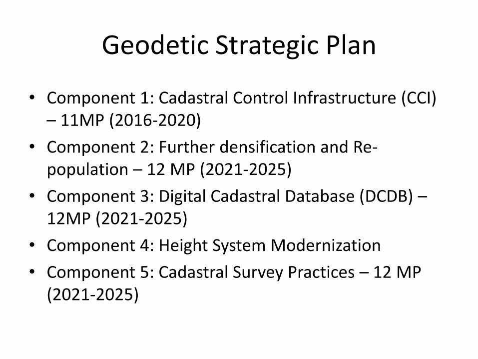
Geodetic Strategic Plan
• Component 1: Cadastral Control Infrastructure (CCI) – 11MP (2016-2020)
• Component 2: Further densification and Re-population – 12 MP (2021-2025)
• Component 3: Digital Cadastral Database (DCDB) – 12MP (2021-2025)
• Component 4: Height System Modernization
• Component 5: Cadastral Survey Practices – 12 MP (2021-2025)
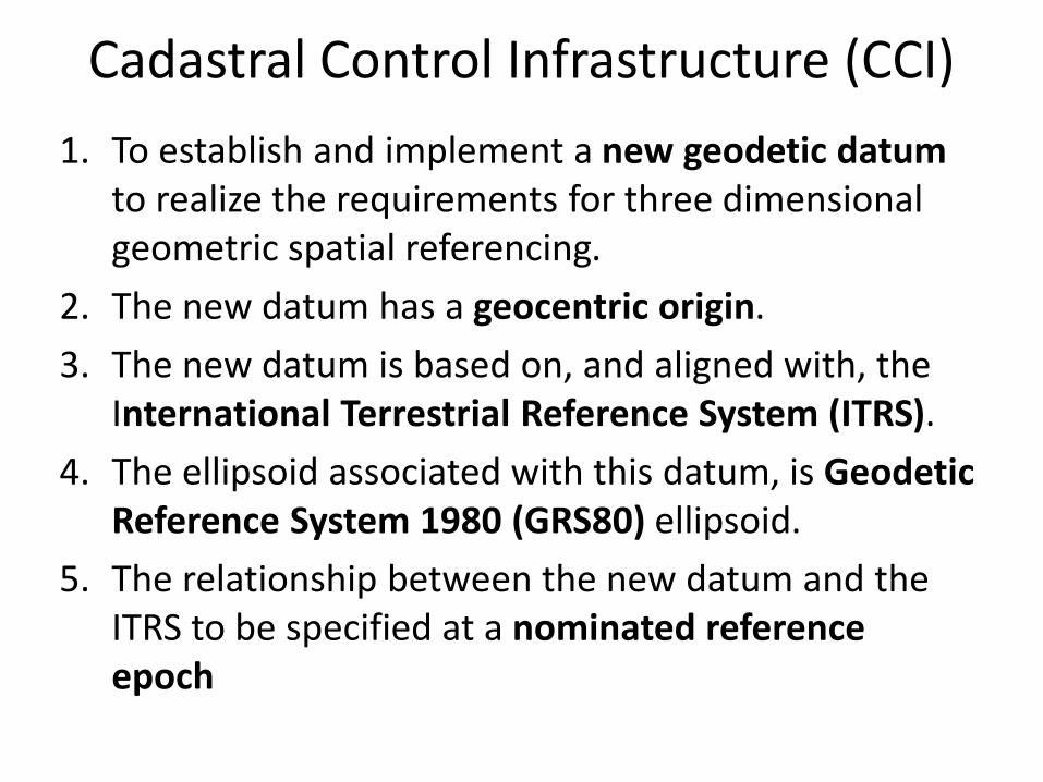
1. To establish and implement a new geodetic datum to realize the requirements for three dimensional geometric spatial referencing.
2. The new datum has a geocentric origin.
3. The new datum is based on, and aligned with, the International Terrestrial Reference System (ITRS).
4. The ellipsoid associated with this datum, is Geodetic Reference System 1980 (GRS80) ellipsoid.
5. The relationship between the new datum and the ITRS to be specified at a nominated reference epoch
Cadastral Control Infrastructure (CCI)
Overview of Land and Survey Geospatial System (LASIS)
• The development of the Land And Survey Information System (LASIS), Phase 1 was initiated in 1984.
• LASIS was officially implemented after the completion of Phase 2 on 6th April 2010.
LASIS Concept
• The primary role of cadastral surveying, mapping and land registration is to form the core data to support the multi-purpose cadastral where application systems for other land management services are developed to support the land administration infrastructure and the legal framework.
• LASIS and cadastral system have been unified into a multi-purpose cadastral system through the adoption of information and GIS technologies, where information about natural resources, planning, land use, land value, land titles, cadastral information are integrated and shared for analysis and decision making relating to land development.
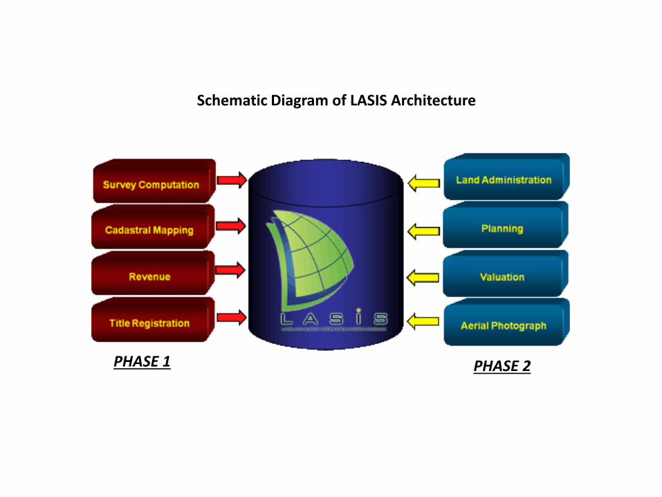
Schematic Diagram of LASIS Architecture
PHASE 1 PHASE 2
System Overview - Challenges
• The challenge is to develop a geospatial information system to support land administration and management which integrates land tenure, land value, land use and land development supported by cadastral, topographic and mapping data.
• Current issues are the lack of effective data modelling for full integration and optimization of the datasets available.
• Long term planning is to implement an enterprise geospatial system through cadastral modelling concept (3D Cadastral) to support spatially enabled governments (SEG), businesses and ubiquitous societies.
LASIS Web & Mobile-Based Applications (eLASIS & mLASIS)
• The challenge of the Department as the way forward is to leverage on the internet technology
• eLASIS project aims to provide efficient and high quality on-line services to the citizens and business communities by extending its services beyond physical barriers of Land and Survey offices, anywhere and anytime.
• The four (4) pioneer online services are as follows: • eMap – Sale of cadastral plans, cartographic maps, aerial
photographs and ortho-photos in both raster and vector format.
• eSearch – Sales and search of Land Title Information. • eLodgement – Online lodgement of land instruments by law
firms. • eSubmission – Online submission of survey jobs to the Land
and Survey Department upon completion of field surveys.

THANK YOU