Embed Size (px)
Citation preview

1
Geo-Solutions Inc Practical Solutions for Soil and Groundwater Construction Problems
26 West Dry Creek Circle Suite 600 Littleton, CO 80120 Phone: 720-283-0505 Fax: 720-283-8055
201 Penn Center Blvd Suite 401 Pittsburgh, PA 15235 Phone: 412-825-5164 Fax: 412-825-5127
Geotechnical Exhibition and
Technical Conference Chicago Illinois – March 26, 1979
SOIL-BENTONITE SLURRY TRENCH CUT-OFF WALLS
David J. D'Appolonia 1 and Christopher R. Ryan2 ABSTRACT Soil-bentonite cut-off walls constructed by slurry trench methods have been employed for about three decades and have gained widespread acceptance during the past five years. Nevertheless, there is virtually no information in the engineering literature concerning the engineering properties pertinent to the design of these facilities. Soil-bentonite cut-off walls are constructed by excavating a continuous narrow trench under a bentonite slurry, which stabilizes the sides of the excavation. The trench is backfilled subsequently with a blended mixture of natural soil and bentonite, thereby displacing the slurry. The completed wall acts as a barrier to lateral flow of water and most fluid pollutants. During the past several years, the writers have been involved in laboratory and field investigations to determine the design factors relating to the impermeability of cut-off walls. One significant question has been the relative contributions of the filter cake and of the backfill itself. This paper presents data which will help the designer in determining the long-term permeability of a cut-off wall and in writing specifications which will achieve the required performance at the lowest cost. Information is presented relating permeability, strength, and compressibility to various types of construction materials that can be employed. A design factor that is increasingly important is the ability of slurry cut-off walls to maintain their integrity under the effect of long-term permeation by various pollutants. Laboratory procedures for modeling the degradation process are described, along with typical results and design methods for minimizing the deterioration of slurry trench cut-off walls due to pollutants. INTRODUCTION Cut-off walls using the soil-bentonite backfill (SB) method of slurry trench construction were first used in the United States in the early 1940’s. Since that time, several hundred ______________________________________________________________________ 1 President-Engineered Construction International, Inc. (1979)
2 President of Geo-Solutions, Inc., Pittsburgh, PA
2
SB cut-offs have been constructed for both temporary and permanent control of seepage into excavations, as foundation and embankment cut-offs for water retaining structures and to prevent seepage of various pollutants from contaminating groundwater. In the past two years, at least 70 permanent slurry trench cut-offs have been constructed in the United States. As geotechnical engineers have become aware of the many advantages, low cost and almost universal success of the method, slurry trench cut-off construction has largely replaced the use of traditional methods such as deep rolled fill cut-offs, grouted cut-offs, and sheet pile cut-offs. Despite the high and increasing rate of use of the method, there is virtually no published data in the engineering literature concerning the engineering properties of SB cut-off materials or the performance of completed field installations. Furthermore, slurry trench specifications have evolved largely from oil field drilling precedent and unevaluated experience rather than systematic field and laboratory investigations of construction feasibility, engineering properties, and actual performance. During the past few years, the writers have been involved in several design-construct projects involving slurry trench construction where rather comprehensive laboratory investigations have been performed to determine the permeability, compressibility, and strength of slurry trench cut-off walls. On several of these projects, tests were conducted to determine the effect of permeation by industrial pollutants on the long-term permeability of the cut-off. This paper summarizes the results of these investigations and presents empirical data relating engineering properties of cut-off walls to the materials employed in their construction. This data will be helpful to designers of slurry trench cut-offs both for purposes of determining and specifying appropriate slurry trench construction materials and construction methods, and for determining the investigations and tests that should be performed as part of the design study. SLURRY TRENCH CUT-OFF CONSTRUCTION A slurry trench cut-off wall is constructed by excavating a narrow vertical trench, typically 2 to 5 feet wide, through the pervious materials to relatively impervious underlying strata. The trench is kept full during excavation with a slurry suspension of bentonite in water. The slurry acts to stabilize the walls of the trench preventing their collapse during excavation. The slurry also deposits a filter cake on the walls of the trench, which con-tributes to the low permeability of the completed cut-off. Numerous experiences in a wide variety of soils from rock to soft clay have shown that a very long and deep trench will remain open, provided that it is filled with slurry and provided the groundwater level is several feet below the slurry level. Trenches more than 100 feet deep and 1000 feet long stay open for several weeks between excavation and backfilling. After excavation, the trench is backfilled, displacing the slurry with an engineered material having the required engineering properties. When impermeability, rather than structural strength, is the required property of the cut-off, the best and least expensive backfill material is usually a paste composed of select soil and bentonite slurry. In special circumstances, concrete or cement-bentonite grout may also be used effectively as the backfill material. ______________________________________________________________________ 1 President-Engineered Construction International, Inc. (1979)
2 President of Geo-Solutions, Inc., Pittsburgh, PA

3
Figure 1 shows the three most commonly used tools for excavating slurry trenches. The optimal method of trench excavation depends on the required depth of cut-off, the subsurface materials and access to the trench at the ground surface. At depths less than about 50 feet, backhoes are generally most efficient. Below this depth, special slurry trenching clamshells or clamshells in combination with backhoes are used. Draglines have been used successfully to depths up to about 80 feet, although their use has been for the most part replaced by more efficient extended backhoes. The method of trench excavation is basically unimportant from a technical point of view. It is only important that the cut-off everywhere extends to the impervious stratum. Verticality of the trench is also irrelevant except as it affects trench continuity. The digging action of backhoes assures that unexcavated material does not remain in the trench provided that rudimentary care is taken. Assurance of trench continuity under clamshell excavation requires more care but is not difficult. The best procedure for ensuring trench continuity is to pass the excavating tools both horizontally and vertically in the trench for its full depth upon completion of excavation. Sometimes thick slurry and sediment are cleaned from the trench bottom with an airlift or clamshell just prior to backfilling. In most instances this exercise is unnecessary because the permeability of any small amount of slurry-encapsulated sediments re-moved is lower than the permeability of the backfill that replaces them. However, if the trench bottom sediments are clean sand and gravel, they should normally be removed. It is good practice to maintain the leading edge of the backfill as close as practical to the point of excavation. The methods for preparing bentonite slurry for introduction into the trench also vary with project size and layout. By far the most commonly used method involves the use of flash-type mixers and circulation ponds as shown in Figure 2. A flash mixer introduces dry bentonite into a highly turbulent water jet, which discharges into a low speed circulation pond where the bentonite is hydrated. This system is well adapted for bulk handling of large slurry volumes. Usually, a two-pond operation is employed, with one pond for mixing and a second pond for storing properly hydrated slurry prior to introduction in the trench. On small projects having a low rate of slurry consumption, it is sometimes more economical to use a high shear vortex or propeller-type mixer and to discharge the slurry directly into the trench. In this case the slurry must be retained in the mixer until hydrated. The method of mixing is technically unimportant to the end product, provided that the proper slurry results from the process. For trenching purposes, slurry having a viscosity equivalent to about 40 seconds-Marsh is ideal. If a premium grade bentonite is used, the slurry will contain about 5 to 6 percent bentonite by weight. The SB backfill material is usually mixed on the ground surface adjacent to the trench using a bulldozer as shown in Figure 3. In special circumstances where space does not permit or where backfill materials are very expensive, mechanical batchers or pugmills have also been used. The backfill material is prepared by sluicing the soil with slurry and then tracking and blading until the mix is homogeneous and the proper consistency is reached. The prepared material is then pushed into the trench at the point where backfill rises to the ground surface, thus avoiding segregation that might be caused by free dropping through the slurry. The slope of the backfill advances by a combination of mud wave and sliding down the face of the previously placed backfill. Figure 4 shows the progression of backfill in a trench having an irregular depth. Ideally, the backfill should not be so stiff that a steep slope will form below the slurry surface, risking the possibility of folding and trapping pockets of slurry within the backfill, nor should it be so fluid that segregation might occur during placement. Ideal placement consistency for most SB backfill materials is achieved when the water content corresponds to a slump of 2 to 6
4
inches. The type of equipment and method used for preparing backfill is unimportant provided that a uniformly homogeneous mix having the required consistency is achieved. The slurry used for sluicing the backfill may be fresh slurry or may be obtained by pumping from the trench. The trench slurry is preferable because it is generally thicker and contains suspended fine materials, which aid in achieving a low permeability backfill. Additionally, removal of slurry from the trench allows for introduction of more fresh slurry thereby reducing the suspended solids load and unit weight. The unit weight of the trench slurry should be maintained significantly lower than the unit weight of the backfill to assure proper displacement of the slurry by the backfill entering the trench. The total unit weight of SB backfill is typically between 105 and 120 pcf. A large body of experience has shown that the backfill will easily displace the slurry provided the slurry unit weight is about 15 pcf less than the backfill unit weight and that the slurry is fluid (slurry taken from the bottom of the trench near the leading edge of the backfill should have a low enough viscosity to pass the marsh funnel). Cleaning the slurry by mechanical demander’s or sedimentation methods to lower values is a complete waste of effort and money and adds nothing to the quality of the final construction. PERMEABILITY OF SOIL/BENTONITE CUT-OFF The permeability of an SB cut-off trench is a function of both the filter cake that forms on the trench walls and the permeability of the backfill placed in the trench. The relative contribution of each constituent depends on the relative permeability and thickness of the two materials. The horizontal permeability of a cut-off wall can be determined from Darcy’s law and a continuity equation:
Where q is flow rate, k is permeability, delta h is head loss and t is thickness Subscripts c and b refer to the filter cake and SB backfill, respectively, and symbols without subscript refer to the overall cut-off wall. Combining equations and considering that tb >> tc leads to:
The permeability of the backfill material can be determined in a laboratory test; the thick-ness of the backfill is selected in design. The ratio kc/tc can also be determined experimentally under simulated field conditions; for a wide variety of practical applications; it varies between the relatively narrow limits of 5 to 25 x 10 –9cm/sec. Figure 5 plots the relationship between overall cut-off permeability and backfill

5
permeability for typical range of values of kc/tc. The plot shows that cut-off permeability is controlled by the backfill when the backfill permeability is low and by the filter cake when the backfill permeability is high. Most interestingly, the cut-off permeability has an effective upper limit of about 10 -6 cm/sec, even for very pervious backfill, due to the thin low permeability filter cake. This is a most significant and important result. A filter cake forms on pervious soils provided that a proper bentonite slurry is used in the trench. Thus, as long as the backfill is sufficiently well graded to prevent extrusion and rupture of the filter cake into the backfill under the design head difference, a cut-off permeability of less than about 10 -6 cm/sec is assured. Filter Cake Permeability When bentonite slurry is caused to flow under a hydraulic gradient into any pervious soil, including low permeability silts, a filter cake forms at the soil-slurry interface. The properties of the filter cake formed on any granular soil are essentially independent of the soil permeability. However, the more pervious the soil, the more the slurry will penetrate the soil before the filter cake forms at the interface. The permeability and thickness of the filter cake so formed depend on the slurry, the difference in head between the slurry and the pore fluid in the soil, and the formation time for the cake. These variables can be studied in a laboratory apparatus where a filter cake is formed on filter paper under controlled conditions representative of field conditions during slurry trench construction. Such an apparatus is shown schematically in Figure 6.The cake is formed by placing slurry over the filter paper and applying a given head to the slurry for a length of time. Excess slurry is then decanted and replaced with water, a head is applied and the flow through the filter cake is measured. The ratio kc/tc is equal to the flow rate divided by the head and the sample area. Figure 7 shows some typical results relating kc/tc to formation head and time for a premium grade natural bentonite and a slurry viscosity of 40 sec-Marsh as commonly used in slurry trench construction. Formation time has a much greater influence oft kc/tc than head for the range of values typical of slurry trenching field conditions. The data strongly suggest that at least one day should elapse between trench excavation and backfill in order to develop a low permeability filter cake. Figure 8 shows the effect of slurry viscosity on kc/tc for the same bentonite at a constant formation head and time. The ratio kc/tc is essentially independent of slurry viscosity provided that the slurry viscosity is greater than about 36 to 38 sec-marsh. A lower slurry viscosity often leads to trench stability problems as well as poor cake formation. A minimum viscosity of 40 sec-marsh is recommended. Filtrate loss properties of the slurry apparently have a negligible influence on kc/tc. Figure 9 shows some data relating kc/tc to the filtrate loss measured in the standard API filter press test. Each data point represents a different bentonite, several of which are chemically treated to improve their yield characteristics. Slurries having a high filtrate loss develop a thicker but more pervious filter cake than slurries having a low filtrate loss. As a result, the ratio kc/tc is relatively unchanged. It is clear that most slurry trench construction specifications place far too much emphasis on filtrate loss properties. This data shows quite clearly that the lowest ratio of kc/tc and hence the lowest cut-off wall permeability is obtained by using a viscous slurry composed of premium grade bentonite with a high unit weight due to suspended fines and a long formation time. In the field, the cake formation is controlled primarily by the depth to groundwater level (and to a

6
relatively lesser extent by slurry unit weight) and thus is not really a design variable. However, all the other variables can be specified by the design. From a practical point of view, the design need only specify the grade of bentonite and the slurry viscosity. Specifying filtrate loss is largely irrelevant, as is any specification as to bentonite yield. The type of bentonite generally used for slurry trench work throughout the industry is known as “premium grade” or “natural” bentonite. Under good mixing conditions with reasonable quality water, bentonite consumption will be about 90 to 100 pounds per cubic yard of slurry. There are several bentonite products on the market which significantly decrease the consumption through the addition of chemicals. Many project specifications attempt to forbid the use of the “peptized” bentonites by specifying “bentonites with no chemical additives.” In fact, there are no bentonites on the market without chemical additives. The American Petroleum Institute allows a certain amount of additives even for the so-called “natural” bentonites. Backfill Permeability The permeability of an SB backfill material is dependent on both the soil gradation and the quantity of bentonite used in blending. Both factors are important. Most construction specifications are very precise concerning the gradation limits of the backfill, but completely neglect any direction concerning the amount of bentonite to be added. This is an error, which can lead to an unsatisfactory end product and an unnecessarily expensive product in those cases where backfill must be imported to meet gradation requirements. The ideal backfill consistency for placement considerations is a saturated paste having, a low enough shear strength so that it will flow easily, yet having sufficient rigidity to stand on a slope of about 10:1. This consistency corresponds to a slump cone value of about 2 to 6 inches and a water content of the SB mixture normally between about 25 and 30 percent. Figure 10 plots water content vs. slump for a wide variety of SB materials; the data suggest that curve is practically unique. Since the backfill mix is prepared by blending soil with slurry (which contains about 6 percent bentonite by weight), the bentonite content of the SB backfill mix is controlled basically by the premix water content of the soil. If the soil is initially dry, the bentonite content in the backfill will be maximum at roughly 2 percent by weight. If on the other hand, the soil to be used for backfill is excavated from below ground water level, it is likely to retain a water content of 10 to 20 percent and the resulting bentonite content of the SB backfill at the proper placement consistency will be on the order of 0.5 to 1.5 percent. Figure 11 plots the relationship between permeability and the quantity of bentonite added to several representative SB backfill samples. Varying the quantity of bentonite between .5 and 1.5 percent typically changes permeability by an order of magnitude, underlining the importance of the water content of the soil before mixing. If the premix water content .of the backfill material is too high, dry bentonite can, of course, be added to a backfill mix. When dry bentonite is required, the best procedure to follow is to spread the backfill in a thin lift and broadcast the bentonite at the desired rate. The dry bentonite should then be blended uniformly into the soil by discing and tracking prior to adding slurry to bring the mix to the proper placement consistency. Figure 11 also demonstrates the large importance of soil gradation on SB backfill permeability. Coarse gradations containing sand and gravel plus about 20 percent nonplastic fines have a permeability one or two orders of magnitude greater than finer gradations containing more fines or plastic fines. The important variable affecting SB

7
backfill permeability is the size of the smallest particles in the soil such as the D10, which is, of course, related to the soil permeability prior to addition of bentonite. The lower the permeability of the soil, the lower will be the permeability of the backfill, other factors being equal. The percentage of soil passing a 200-mesh sieve is much easier to measure and control in the field and is used herein. Figure 12 plots the permeability of a large number of SB backfill materials as a function of fines content (percentage passing a No. 200 sieve). All of the materials had a premix water content of roughly 10 to 15 percent and molded water content corresponding to a slump of 3 to 6 after addition of bentonite slurry (dry bentonite was not added). These conditions are typical of field practice and, in fact, many of the data points shown in Figure 12 are from field samples. The data suggest two distinct families of curves, one corresponding to plastic and the other nonplastic or low plasticity fines. A much lower backfill permeability is achieved by addition of plastic fines to the blend. Addition of clay to the backfill does not result in a low permeability unless the clay particles are well distributed throughout the mix. A typical situation for a cut-off involves penetrating a sand layer and keying two or three feet into an underlying clay layer. If the sand is 20 feet thick, for example, a three-foot key into the clay would produce a potential backfill mix consisting of a clayey sand with about 15 percent plastic fines. However, tracking and blending with a bulldozer generally will not break the clay down completely and the resulting backfill will be slightly clayey sand with clay lumps. The clay lumps act like gravel particles and do not greatly diminish the permeability of the SB material. The above data show that a low permeability backfill is achieved by blending an adequate amount of bentonite with soil containing a significant percentage of fines, and preferably plastic fines. In most applications, a minimum bentonite content of 1 percent and at least 20 percent fines are recommended. The backfill design and specification should consider and control both factors. Controlling the gradation of the sand and gravel size particles in the mix has no significant effect on the backfill permeability. Additionally, it is advantageous to use slurry pumped from the trench rather than slurry from the hydration pond to prepare the backfill. The trench slurry will have a somewhat higher bentonite concentration and a much higher fines content than freshly prepared slurry. The backfill mix must, of course, also be workable from a construction point of view. A surprisingly wide variety of materials have been mixed in the field by blading and tracking. Materials ranging from weathered shales to weathered conglomerates, and from sand and gravel to sandy clay and clay tills have been blended and placed readily and successfully. Backfill Compressibility and Strength Compressibility and strength are generally not major design considerations for a seepage cut-off. However, there are significant exceptions, for example, when a structure such as a dam is to be constructed over the cut-off. In these cases the designer will generally wish to keep the cut-off compressibility compatible with the compressibility of the surrounding ground, in order to minimize differential movement of the earth structure and resultant stress concentrations in the earth structure or its foundation. If shear deformations are anticipated, the cut-off must support the movements associated with the surrounding ground without cracking or developing

8
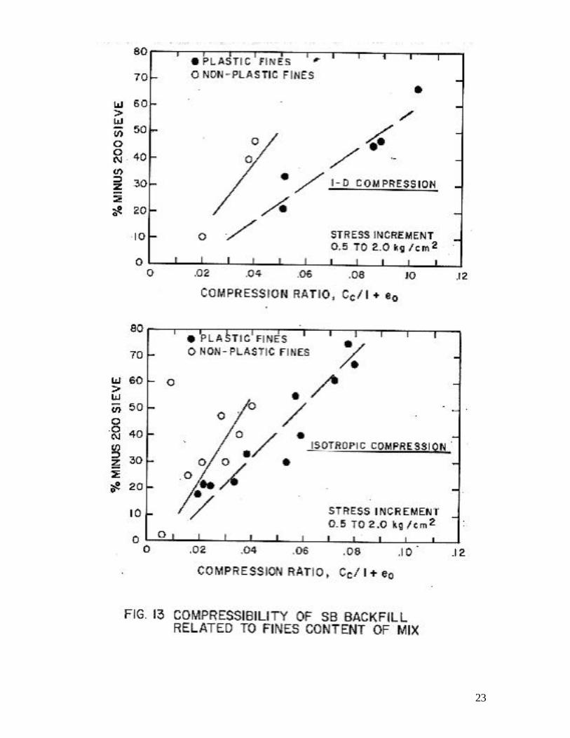
shear planes that might lead to an increase in the effective permeability of the cut-off. Once consolidated under its own weight, most SB backfill materials have a relatively low compressibility. Compressibility depends chiefly on the percentage of granular bulky-shaped particles in the gradation. Comparatively low compressibility results when there is sufficient granular material in the mix to allow grain-to-grain contact between the granular particles. Figure 13 plots the relationship between compressibility and fines content for a number of SB backfill materials. Compressibility is expressed as the compression ratio in the stress range 0.5 to 2.0 kg /cm2 which is the stress increment of interest in many field loading situations. Data are presented for both one-dimensional and isotropic compression. An SB backfill material containing between 10 and 40 percent fines generally has a compression ratio of 0.02 to 0.07 with the higher values associated with the higher fines content samples and samples containing higher plasticity fines. Low permeability and low compressibility are, of course, contradictory requirements because the large percentage of plastic fines required for low permeability results in higher compressibility. An optimum material combining both low compressibility and permeability consists of a granular matrix whose interstices are filled with fine grained soils and bentonite, such as a well graded sand or sand and gravel with about 20 to 30 percent plastic fines. If the mix also contains more than about 1 percent bentonite by weight, permeability will be on the order of 10 -7 cm/sec or less. However, when low compressibility is not required, a higher fines content is desirable and the coarse end of the gradation curve becomes completely unimportant. An SB material containing a significant percentage of fines behaves as a perfectly plastic or strain-hardening frictional material (much like a remolded soft sandy clay or clayey sand). Characteristic stress-strain curves for SB materials in triaxial compression are shown in Figure 14, together with typical effective stress paths in undrained shear. Samples generally fail by bulging; distinct shear planes develop only at large strains in heavily consolidated samples. The degree of plasticity is, of course, controlled by the amount of fines in the backfill blend. In terms of effective stress parameters, strength is mobilized primarily by internal friction and thus depends primarily on consolidation stress. The axial strain at failure in drained shear is usually 10 to 20 percent. In undrained shear, the strain at failure (defined at maximum obliquity) is typically 5 to 10 percent with the undrained shear strength on the order of 30 to 60 percent of the effective consolidation stress. The angle of internal friction is usually between 30 to 35 degrees. EFFECT OF POLLUTANT PERMEATION ON CUT-OFF PERMEABILITY Permeation of a bentonite filter cake or soil-bentonite backfill by polluted water generally leads to an increased permeability. Two mechanisms can contribute to the permeability increase. First, the soil minerals themselves may be soluble in the permeant, which might lead to a loss of solids and a corresponding increase in pore volume and soil permeability. Second, the pore fluid substitution may lead to a smaller double layer of the partially bound water surrounding the hydrated bentonite or other clay particles, reducing the effective size of the clay particles that clog the pore space between soil grains, and thereby increasing the size of the effective flow channels in the soil skeleton and the permeability. Two independent factors associated with the pore fluid substitution can contribute to this second mechanism: 1- the salt concentration of the pore fluid

9
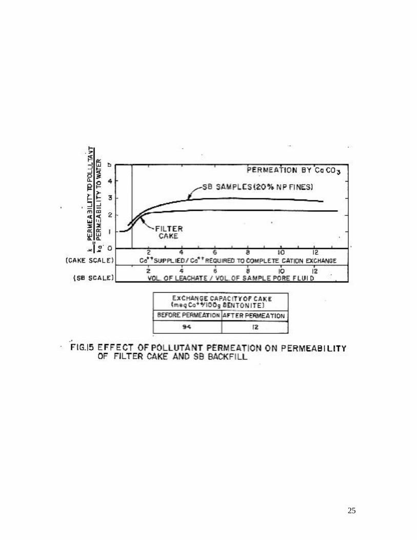
affects the difference in electrical potential between the clay particle and the free-pore water which controls how tightly the double-layer water is held, and 2- the sodium ions associated with the sodium montmorillonite (bentonite) readily exchange with multivalent ions (such as calcium) carried in the pollutant which also leads to a smaller double layer. The permeation time required for the changes associated with pore fluid substitution to be completed is relatively short. once a sample has been permeated by a volume of pollutant equal to about twice the volume of the pore fluid in the sample, the initial pore fluid has been, for the most part, leached out and the new pore fluid is essentially the pollutant. The time required to complete the cation exchange is related to the sodium cation exchange potential of the bentonite and the concentration of exchangeable cations carried by pollutant. Since sodium readily exchanges with multivalent cations such as calcium, magnesium and heavy metals, the exchange is typically complete once an equivalent number of ions are supplied by the permeant to satisfy the total cation ex-change capacity of the bentonite. Once both the pore fluid is substituted and the cation exchange occurs, steady state conditions prevail and the permeability remains constant at a higher value associated with the new pore fluid and the new cation montmorillonite. These points are illustrated by Figure 15, which plots permeability for both bentonite filter cakes and SB backfill as a function of permeation time with a calcium carbonate. The time scale in the plots is ex-pressed as either the ratio of the leachate volume to the pore fluid volume or the ratio of exchangeable cations supplied by the permeant to the cations required to satisfy the total cation exchange capacity of the bentonite. Pore fluid substitution can lead to a piping failure of an SB material if fines are not used in the blend. For example, addition of 2 to 3 percent bentonite by weight to a clean fine sand will result in a material having a permeability between 10 -6 and 10 -7 cm/sec. Prolonged permeation of this soil by calcium-rich water will at first lead to only a small increase in permeability, but eventually a rather sudden piping failure will almost invariably occur. Because of the small amount of clay in the blend, primarily the sand grains carry the intergranular stress, with the water-swollen bentonite merely blocking the large pores in the sand matrix. Apparently, the combination of cation exchange and in-crease in salt concentration reduce the size of the bound water around the clay particles to the point that the clay can be physically eroded out of the sand matrix under the seepage forces. A large number of long-term tests conducted at high gradients (typically 100 to 200) indicate that these phenomena do not occur when a significant percentage of soil fines are included in the SB backfill mix. In cases where the cost of obtaining a sand backfill with fines is high, there are several bentonites on the market which, through the addition of long-chain polymers, bond the bentonite particles to the soil matrix. Use of these bentonites may prevent the piping mode of failure. Table 1 gives a qualitative summary of the effect of permeation by various pollutants on the permeability of both filter cakes and SB backfill mixes. The table provides only a qualitative approximation of the likely effect of pollutant permeation. Tests should always be conducted using the specific SB materials from the site and the actual pollutant in de-signing a cut-off. Nevertheless, the results of a large number of experiments on a variety of materials using a range of representative pollutants lead to the following general observations:
1- Well-graded SB materials containing more than 20 percent plastic fines and about 1 percent bentonite exhibit only a small increase in permeability even when permeated by concentrated salt solutions at pH between about 2 and

10
11. The same small effect is found with filter cakes formed with premium grade natural bentonites. Coarse soils containing no fines (e.g., clean sands) having a higher bentonite content can exhibit a large permeability increase and actually fail by piping.
2- Very low and very high pH have a greater effect on permeability and extremely basic solutions usually produce a greater permeability increase than strong acids. (Amorphous silica becomes quite soluble in highly alkaline solutions.)
3- For a proper SB backfill containing plastic fines, no apparent advantage is achieved by using specially treated bentonites. However, when used with clean gradations without fines, these polymer-treated products may have an advantage.
4- A properly designed backfill that is already contaminated with the pollutant is preferable to uncontaminated backfill because a smaller change will be induced in the SB material during subsequent permeation with the pollutant.
Generalizations concerning solubility should not be made. Strong acids or strong bases can dissolve or alter either the bentonite or the soil portion of the SB material and lead to large permeability increases. If confronted with these types of permeants, the designer should definitely conduct tests to determine the effect of prolonged permeation. Several types of tests can be conducted. The SB backfill or filter cake can be permeated and the permeability observed with time; most importantly, the leachate should be chemically analyzed to determine the extent of solutioning. Another test is to wash the soil materials repeatedly in the permeant and quantitatively analyze the ion content of the extracted samples. SUMMARY It is fair to say that many of the slurry trench cut-off walls built in the United States have employed designs which were not necessarily based on project requirements. The same specifications are commonly applied to totally different projects, e.g., a shallow cut-off for temporary dewatering and a deep permanent cut-off under a dam. The computed flows for various designs should be considered in relation to the flow around and under the i2ut-off wall and applicable environmental concerns when determining the required engineering properties of the cut-off. Once design criteria are set, the Engineer should use tests and analyses, such as presented herein, to establish the specific construction methods and materials to be employed. Based on the results reported in this paper, the writers recommend the following provisions to be included in specifications where permeability of about 10-6 cm/sec is required:
1 Type of Bentonite: Specify type of bentonite by grade, usually “a natural premium-grade Wyoming bentonite,” or by bentonite consumption in slurry. References to filtrate loss and degree of hydration are then superfluous.

11
2 Slurry Viscosity: A minimum viscosity of 40 seconds-Marsh is normally required to assure trench stability and good filter cake formation. Additionally, the slurry in the trench should maintain some fluidity as evidenced by its ability to pass through a Marsh Funnel, so that it can be properly displaced by the backfill.
3 Slurry Unit Weight: The density of the in-trench slurry, as sampled near the bottom, should be at least 15 pcf lighter than the backfill so that the slurry will be properly displaced.
4 Trench Bottom Cleaning: Sediments at the bottom of the trench may cause no problem, since they are surrounded by slurry. In cases where sufficient time passes that sediments build up to unacceptable levels or are of a gradation which might contribute to piping through the wall, it may be necessary to remove them. Specifications should be written with the performance criteria in mind and only require removal of sediments when necessary.
5 Backfill: For optimum workability, the backfill should have a slump of 4-6 inches. It should be composed of natural soils blended with bentonite slurry. Twenty to forty percent fines is the ideal range. Pockets of clean granular soils should not be permitted because the filter cake can be pushed off the upstream wall into the voids in the backfill and ruptured.
Specifications, which incorporate the above provisions along with the usual provisions for depth, continuity, quality control, etc., will yield a sound cut-off wall adequate for many temporary walls and even for permanent walls where a very low permeability is not required. Where very low permeability is necessary, the additional provisions outlined below will reduce wall permeability to 10 -7 cm/sec or lower.
1 Fines Content of Backfill: The backfill should consist of well-graded silty or clayey sands. The ideal percentage of fines is in the range of 20 to 30 percent to minimize both permeability and compressibility. For maximum impermeability, a greater percentage of fines can be used and the fines should be plastic.
2 Bentonite Content of Backfill: A minimum bentonite content of 1 percent is recommended. Either the water content of the soil prior to mixing should be controlled, or dry bentonite should be added to the mix so that the backfill blend contains adequate bentonite.
In cases where the fluid to be contained by the cut-off is a pollutant, minimum permeability is usually desired. In addition, there is always a concern for the effect on the permeability of the wall due to long-term permeation by pollutants. With a properly designed backfill, and for the majority of the pollutants tested to date, the increase in permeability can be kept within tolerable limits by adjusting backfill gradations. It is, however, essential to test any pollutant with the actual backfill mix using sufficient permeation time so that ion exchange and pore fluid substitution is substantially complete. A check should be made to see if solutioning of either the bentonite or the soil

12
matrix will occur. It is preferable to use backfill that is already contaminated, as this mix will undergo less change during permeation. In conclusion, this paper has presented data that a designer can apply to the design of slurry cut-off walls. As the application of slurry trench construction continues to expand, data must be collected so that the Industry’s understanding of the parameters controlling performance will continue to improve. Above all else, it is clear that the designer must evaluate performance criteria, environmental factors, available materials and other pertinent considerations to arrive at cost-effective design for a slurry trench cut-off wall.

13
14

15

16

17

18

19

20

21

22
23

24
25