Embed Size (px)
Citation preview

1 | P a g e Copyright 2018 Geo Products, LLC, All rights reserved
Design and Installation Guidelines
for Soil Stabilization
Geo Products, LLC
12626 North Houston Rosslyn Road Houston, TX 77086
Phone: 281.820.5493 Fax: 281.820.5499
www.geoproducts.org
2 | P a g e Copyright 2018 Geo Products, LLC, All rights reserved
Design Guidelines for Soil Stabilization 3
The EnviroGrid® Solution 4
Designing with EnviroGrid® 5-8
Installation 9-21
Legal Notice 22

3 | P a g e Copyright 2018 Geo Products, LLC, All rights reserved
Design Guidelines for Soil Stabilization
When traffic loads are applied to a soil subgrade, the soil will not deform or rut if the shear
strength of the soil exceeds the applied loads. The strength of the soil is a function of such
characteristics as its angle of internal friction, its cohesion, and its degree of compaction.
Most road and parking systems consists of one or more layers of good quality fill materials placed
and compacted on soil subgrades. The fill materials allow the system to support traffic loads that
the soil, by itself, would not be able to withstand. The function of the layer(s) of base material is
to distribute the imposed loads over a large area, thereby reducing the pressure (load divided by
area), which is transferred to the subgrade. The base material is able to distribute the loads
because the individual aggregate particles lock together. Applied loads are transmitted through
the base material both as vertical and horizontal forces.
If the horizontal (lateral) forces push the base material sideways, rutting develops, resulting in a
thinner layer less able to resist additional load applications which leads to failure. Even a good
quality base material, with the proper internal strength and interlocking of individual particles,
can be forced to move laterally. The poor quality subgrade in contact with the base material
does not provide the required friction at the interface to restrain the movement.
4 | P a g e Copyright 2018 Geo Products, LLC, All rights reserved
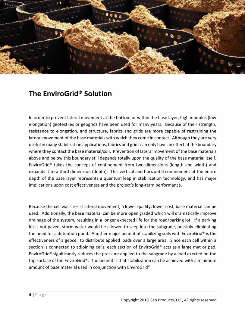
The EnviroGrid® Solution
In order to prevent lateral movement at the bottom or within the base layer, high modulus (low
elongation) geotextiles or geogrids have been used for many years. Because of their strength,
resistance to elongation, and structure, fabrics and grids are more capable of restraining the
lateral movement of the base materials with which they come in contact. Although they are very
useful in many stabilization applications, fabrics and grids can only have an effect at the boundary
where they contact the base material/soil. Prevention of lateral movement of the base materials
above and below this boundary still depends totally upon the quality of the base material itself.
EnviroGrid® takes the concept of confinement from two dimensions (length and width) and
expands it to a third dimension (depth). This vertical and horizontal confinement of the entire
depth of the base layer represents a quantum leap in stabilization technology, and has major
implications upon cost effectiveness and the project’s long-term performance.
Because the cell walls resist lateral movement, a lower quality, lower cost, base material can be
used. Additionally, the base material can be more open graded which will dramatically improve
drainage of the system, resulting in a longer expected life for the road/parking lot. If a parking
lot is not paved, storm water would be allowed to seep into the subgrade, possibly eliminating
the need for a detention pond. Another major benefit of stabilizing soils with EnviroGrid® is the
effectiveness of a geocell to distribute applied loads over a large area. Since each cell within a
section is connected to adjoining cells, each section of EnviroGrid® acts as a large mat or pad.
EnviroGrid® significantly reduces the pressure applied to the subgrade by a load exerted on the
top surface of the EnviroGrid®. The benefit is that stabilization can be achieved with a minimum
amount of base material used in conjunction with EnviroGrid®.
5 | P a g e Copyright 2018 Geo Products, LLC, All rights reserved
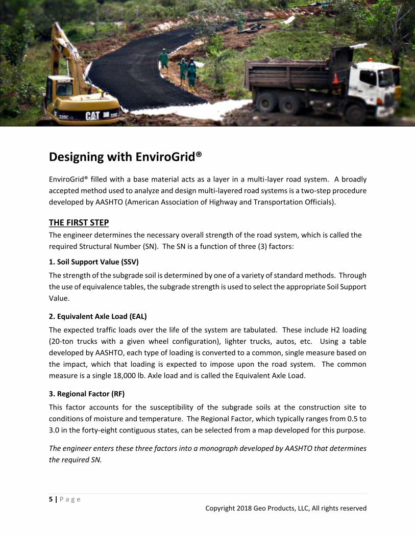
Designing with EnviroGrid®
EnviroGrid® filled with a base material acts as a layer in a multi-layer road system. A broadly
accepted method used to analyze and design multi-layered road systems is a two-step procedure
developed by AASHTO (American Association of Highway and Transportation Officials).
THE FIRST STEP
The engineer determines the necessary overall strength of the road system, which is called the
required Structural Number (SN). The SN is a function of three (3) factors:
1. Soil Support Value (SSV)
The strength of the subgrade soil is determined by one of a variety of standard methods. Through
the use of equivalence tables, the subgrade strength is used to select the appropriate Soil Support
Value.
2. Equivalent Axle Load (EAL)
The expected traffic loads over the life of the system are tabulated. These include H2 loading
(20-ton trucks with a given wheel configuration), lighter trucks, autos, etc. Using a table
developed by AASHTO, each type of loading is converted to a common, single measure based on
the impact, which that loading is expected to impose upon the road system. The common
measure is a single 18,000 lb. Axle load and is called the Equivalent Axle Load.
3. Regional Factor (RF)
This factor accounts for the susceptibility of the subgrade soils at the construction site to
conditions of moisture and temperature. The Regional Factor, which typically ranges from 0.5 to
3.0 in the forty-eight contiguous states, can be selected from a map developed for this purpose.
The engineer enters these three factors into a monograph developed by AASHTO that determines
the required SN.
6 | P a g e Copyright 2018 Geo Products, LLC, All rights reserved
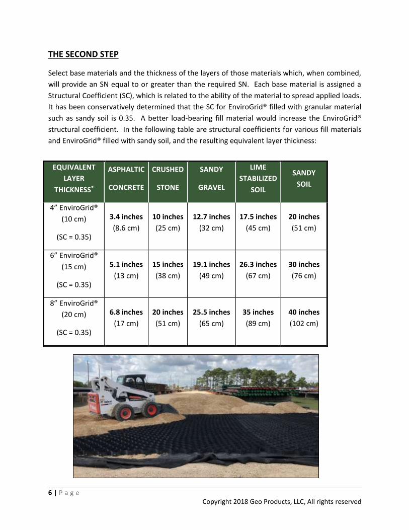
THE SECOND STEP
Select base materials and the thickness of the layers of those materials which, when combined,
will provide an SN equal to or greater than the required SN. Each base material is assigned a
Structural Coefficient (SC), which is related to the ability of the material to spread applied loads.
It has been conservatively determined that the SC for EnviroGrid® filled with granular material
such as sandy soil is 0.35. A better load-bearing fill material would increase the EnviroGrid®
structural coefficient. In the following table are structural coefficients for various fill materials
and EnviroGrid® filled with sandy soil, and the resulting equivalent layer thickness:
EQUIVALENT
LAYER
THICKNESS*
ASPHALTIC
CONCRETE
CRUSHED
STONE
SANDY
GRAVEL
LIME
STABILIZED
SOIL
SANDY
SOIL
4” EnviroGrid®
(10 cm)
(SC = 0.35)
3.4 inches
(8.6 cm)
10 inches
(25 cm)
12.7 inches
(32 cm)
17.5 inches
(45 cm)
20 inches
(51 cm)
6” EnviroGrid®
(15 cm)
(SC = 0.35)
5.1 inches
(13 cm)
15 inches
(38 cm)
19.1 inches
(49 cm)
26.3 inches
(67 cm)
30 inches
(76 cm)
8” EnviroGrid®
(20 cm)
(SC = 0.35)
6.8 inches
(17 cm)
20 inches
(51 cm)
25.5 inches
(65 cm)
35 inches
(89 cm)
40 inches
(102 cm)
7 | P a g e Copyright 2018 Geo Products, LLC, All rights reserved
Alternatively, if the engineer knows how much of a base material is normally used in a given
design, he or she can substitute EnviroGrid® for that material in relation to their structural
coefficients. For example, EnviroGrid® filled with sandy soil has five times (.35/.07=5) the support
value of sandy soil without EnviroGrid®. Thus, 4” EnviroGrid® filled with sandy soil has the same
load bearing strength as 20” of sandy soil without EnviroGrid®. Therefore, if a road design calls
for 18” of a sandy soil fill, the engineer could reduce that amount to 4” EnviroGrid® with the same
type fill and have a stronger base.
The designer can add local fill materials to the above table with the appropriate AASHTO
structural coefficients to calculate the savings using EnviroGrid®. Examples of such locally
available materials are crushed shell in coastal areas, river gravel in mountainous areas, coal slag
from mining projects and high quality limestone in other areas.
A complete description of the AASHTO design procedure, as well as its development and
complete software for use in design, is available from AASHTO at (202)624-5800 or at
www.aashto.org.
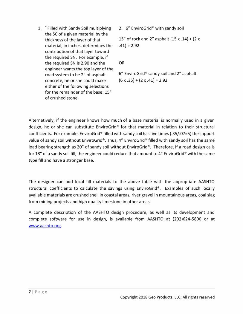
1. * Filled with Sandy Soil multiplying the SC of a given material by the thickness of the layer of that material, in inches, determines the contribution of that layer toward the required SN. For example, if the required SN is 2.90 and the engineer wants the top layer of the road system to be 2” of asphalt concrete, he or she could make either of the following selections for the remainder of the base: 15” of crushed stone
2. 6” EnviroGrid® with sandy soil
15” of rock and 2” asphalt (15 x .14) + (2 x
.41) = 2.92
OR
6” EnviroGrid® sandy soil and 2” asphalt
(6 x .35) + (2 x .41) = 2.92

8 | P a g e Copyright 2018 Geo Products, LLC, All rights reserved
Installation Manual
INSTALLATION COMPONENTS
ENVIROCLIPS TWIST ANCHORS
Staking or pinning EnviroGrid® is the common anchoring method used to hold the panels in placed when they are being filled to prevent movement. The EnviroClips are the preferred type of anchoring pins. Features and benefits of the EnviroClips
Quick and easy to install with an electric drill and custom chuck - 5 times faster installation process compared to standard stakes
Eliminates time, labor, and safety concerns from carrying and hammering heavy rebar on steepened slopes
Clips into the perforated side walls of the EnviroGrid
Superior performance when compared to traditional rebar J-hooks, up to 9 times the pull out force of J-hooks
Can be installed to full depth without damaging or rising above the EnviroGrid® wall Typical detail drawings of pin locations are available. If no engineer recommendations are provided, use one EnviroClip per square meter/yard of EnviroGrid®.
EnviroClip
9 | P a g e Copyright 2018 Geo Products, LLC, All rights reserved
EnviroLocks
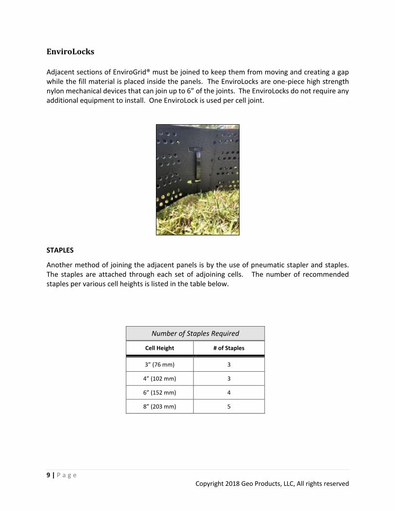
Adjacent sections of EnviroGrid® must be joined to keep them from moving and creating a gap while the fill material is placed inside the panels. The EnviroLocks are one-piece high strength nylon mechanical devices that can join up to 6” of the joints. The EnviroLocks do not require any additional equipment to install. One EnviroLock is used per cell joint.
STAPLES
Another method of joining the adjacent panels is by the use of pneumatic stapler and staples. The staples are attached through each set of adjoining cells. The number of recommended staples per various cell heights is listed in the table below.
Number of Staples Required
Cell Height # of Staples
3” (76 mm) 3
4” (102 mm) 3
6” (152 mm) 4
8” (203 mm) 5
10 | P a g e Copyright 2018 Geo Products, LLC, All rights reserved
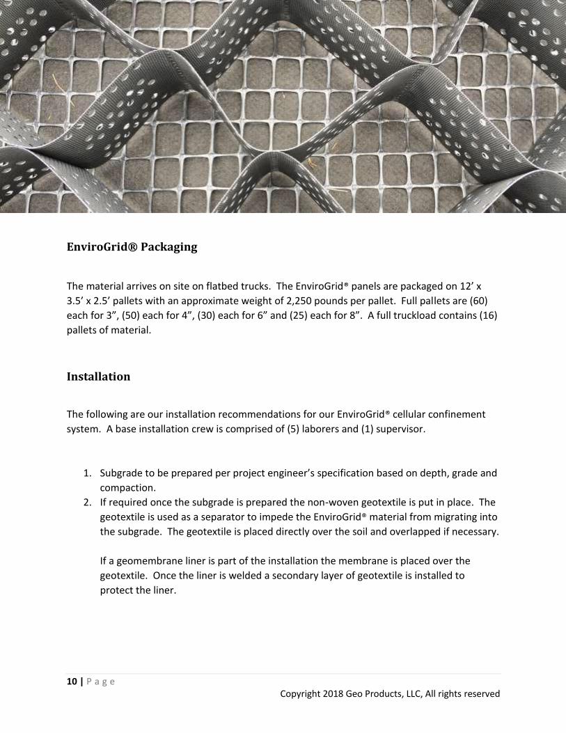
EnviroGrid® Packaging
The material arrives on site on flatbed trucks. The EnviroGrid® panels are packaged on 12’ x
3.5’ x 2.5’ pallets with an approximate weight of 2,250 pounds per pallet. Full pallets are (60)
each for 3”, (50) each for 4”, (30) each for 6” and (25) each for 8”. A full truckload contains (16)
pallets of material.
Installation
The following are our installation recommendations for our EnviroGrid® cellular confinement
system. A base installation crew is comprised of (5) laborers and (1) supervisor.
1. Subgrade to be prepared per project engineer’s specification based on depth, grade and
compaction.
2. If required once the subgrade is prepared the non-woven geotextile is put in place. The
geotextile is used as a separator to impede the EnviroGrid® material from migrating into
the subgrade. The geotextile is placed directly over the soil and overlapped if necessary.
If a geomembrane liner is part of the installation the membrane is placed over the
geotextile. Once the liner is welded a secondary layer of geotextile is installed to
protect the liner.
11 | P a g e Copyright 2018 Geo Products, LLC, All rights reserved
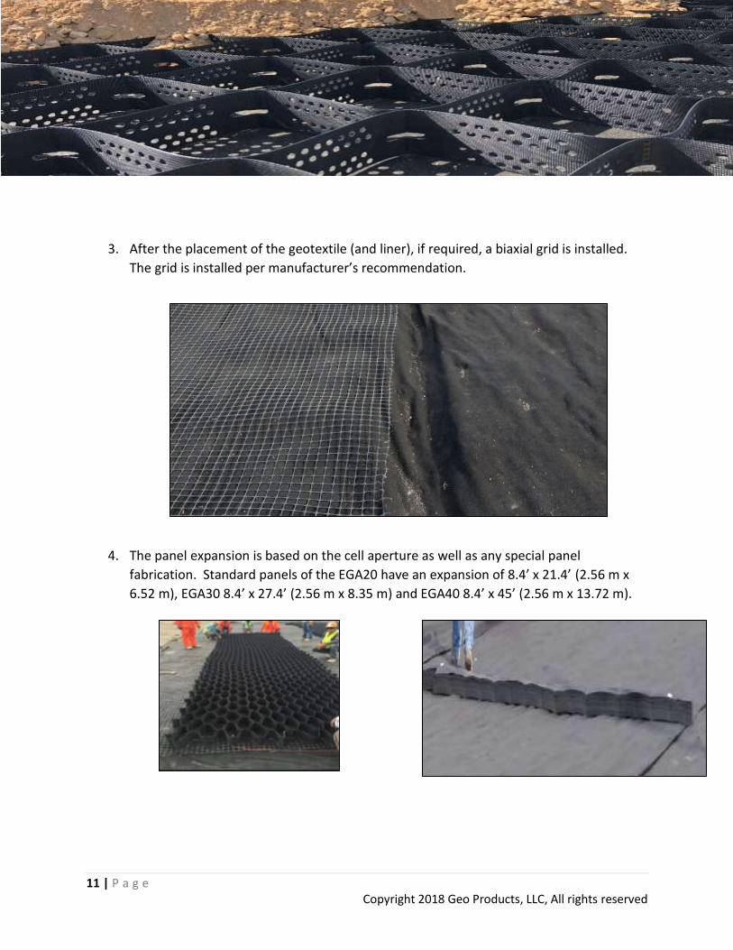
3. After the placement of the geotextile (and liner), if required, a biaxial grid is installed.
The grid is installed per manufacturer’s recommendation.
4. The panel expansion is based on the cell aperture as well as any special panel
fabrication. Standard panels of the EGA20 have an expansion of 8.4’ x 21.4’ (2.56 m x
6.52 m), EGA30 8.4’ x 27.4’ (2.56 m x 8.35 m) and EGA40 8.4’ x 45’ (2.56 m x 13.72 m).
12 | P a g e Copyright 2018 Geo Products, LLC, All rights reserved
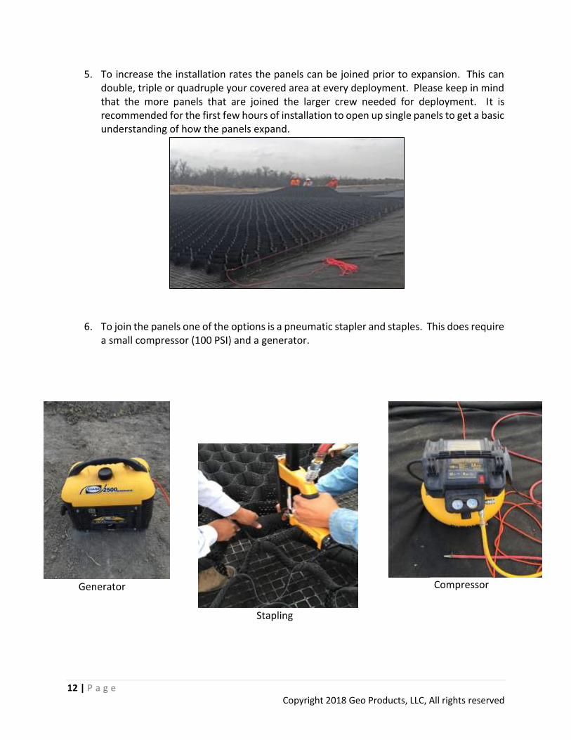
5. To increase the installation rates the panels can be joined prior to expansion. This can double, triple or quadruple your covered area at every deployment. Please keep in mind that the more panels that are joined the larger crew needed for deployment. It is recommended for the first few hours of installation to open up single panels to get a basic understanding of how the panels expand.
6. To join the panels one of the options is a pneumatic stapler and staples. This does require a small compressor (100 PSI) and a generator.
Generator
Stapling
Compressor
13 | P a g e Copyright 2018 Geo Products, LLC, All rights reserved
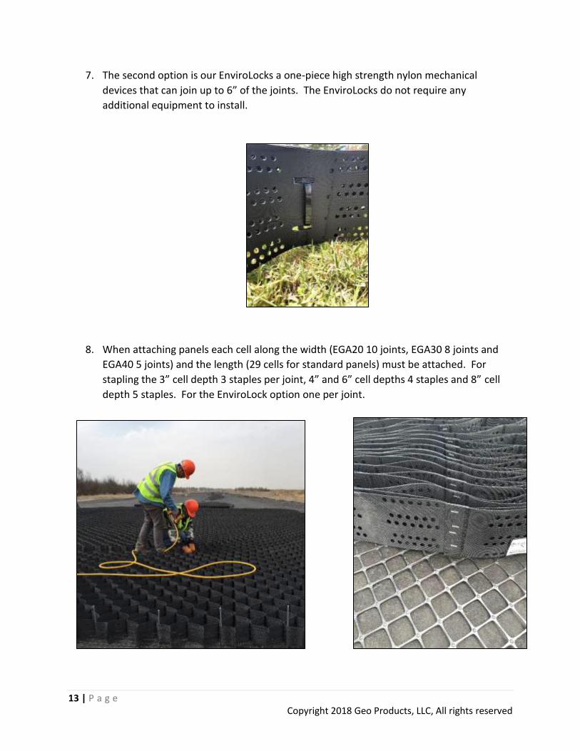
7. The second option is our EnviroLocks a one-piece high strength nylon mechanical
devices that can join up to 6” of the joints. The EnviroLocks do not require any
additional equipment to install.
8. When attaching panels each cell along the width (EGA20 10 joints, EGA30 8 joints and
EGA40 5 joints) and the length (29 cells for standard panels) must be attached. For
stapling the 3” cell depth 3 staples per joint, 4” and 6” cell depths 4 staples and 8” cell
depth 5 staples. For the EnviroLock option one per joint.

14 | P a g e Copyright 2018 Geo Products, LLC, All rights reserved
9. When pre-joining the panels it is recommended to have a crew of (2) workers doing this
ahead of the installation crew and staging the pre-joined panels at the end of the
appropriate expansion length.
10. When expanding the panels it is advisable to get the full length of expansion. Once the
panels are pulled to the appropriate length (EGA20 21.4’, EGA30 27.4’, EGA40 45’) the
width will be set at the correct 8.4’. In this manner you insure proper coverage and
yield per panel. If a geomembrane liner is part of the system STAKES are not permitted.
The panels can be expanded with the use of sand bags around the perimeter or with a
stretcher frame.
11. It is also recommended to use a string line to keep your outside edge of the panels in
line based on your layout.
15 | P a g e Copyright 2018 Geo Products, LLC, All rights reserved
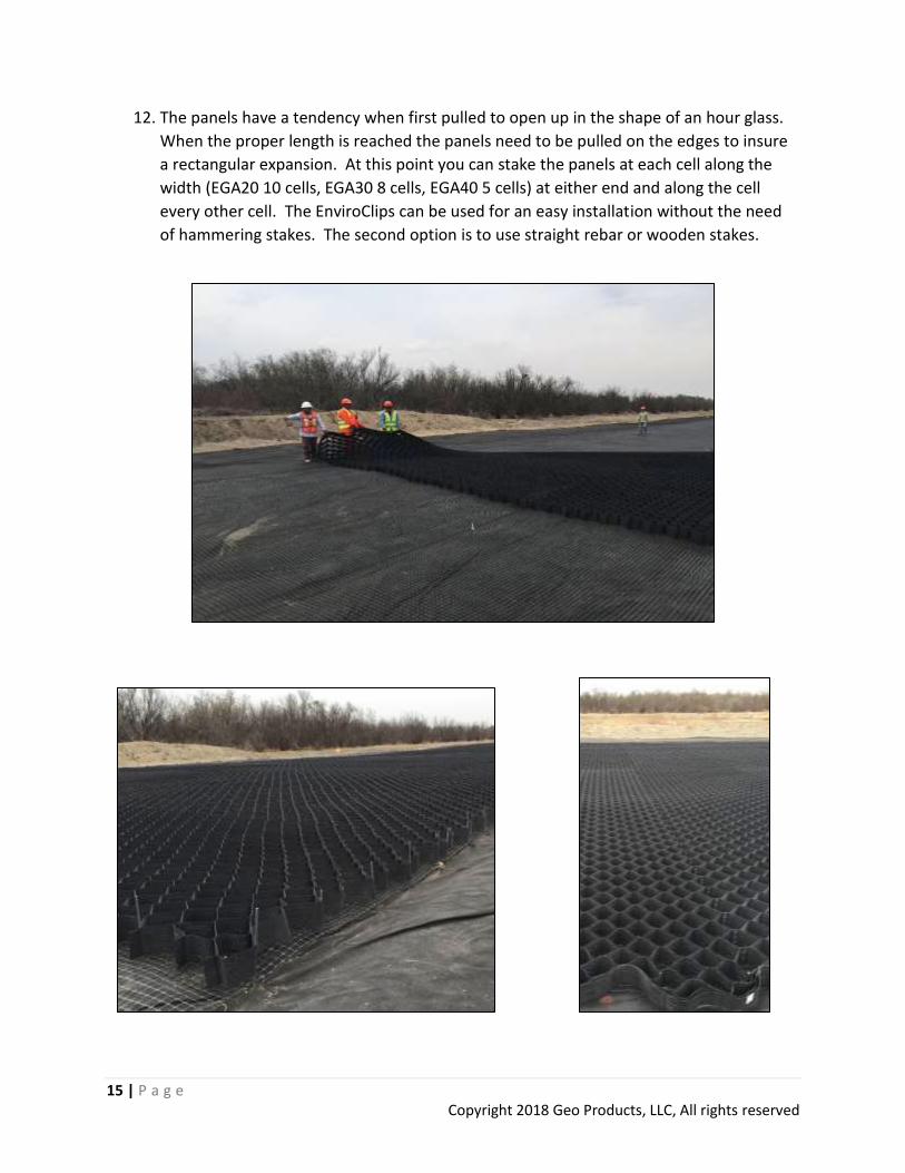
12. The panels have a tendency when first pulled to open up in the shape of an hour glass.
When the proper length is reached the panels need to be pulled on the edges to insure
a rectangular expansion. At this point you can stake the panels at each cell along the
width (EGA20 10 cells, EGA30 8 cells, EGA40 5 cells) at either end and along the cell
every other cell. The EnviroClips can be used for an easy installation without the need
of hammering stakes. The second option is to use straight rebar or wooden stakes.
16 | P a g e Copyright 2018 Geo Products, LLC, All rights reserved
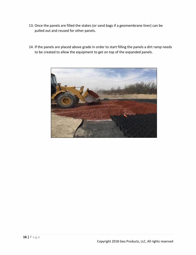
13. Once the panels are filled the stakes (or sand bags if a geomembrane liner) can be
pulled out and reused for other panels.
14. If the panels are placed above grade in order to start filling the panels a dirt ramp needs
to be created to allow the equipment to get on top of the expanded panels.
17 | P a g e Copyright 2018 Geo Products, LLC, All rights reserved
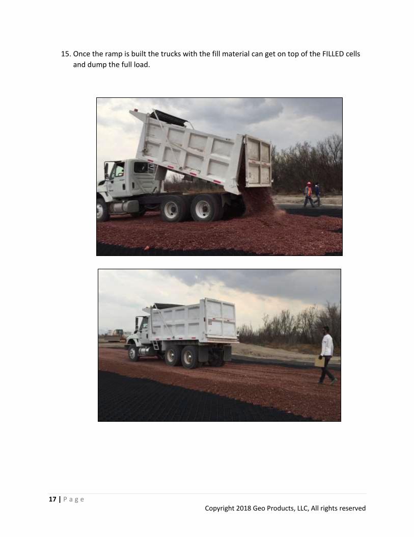
15. Once the ramp is built the trucks with the fill material can get on top of the FILLED cells
and dump the full load.
18 | P a g e Copyright 2018 Geo Products, LLC, All rights reserved
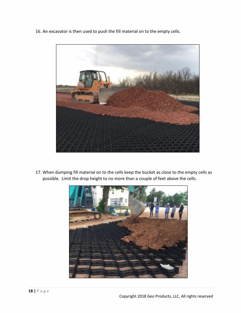
16. An excavator is then used to push the fill material on to the empty cells.
17. When dumping fill material on to the cells keep the bucket as close to the empty cells as
possible. Limit the drop height to no more than a couple of feet above the cells.
19 | P a g e Copyright 2018 Geo Products, LLC, All rights reserved
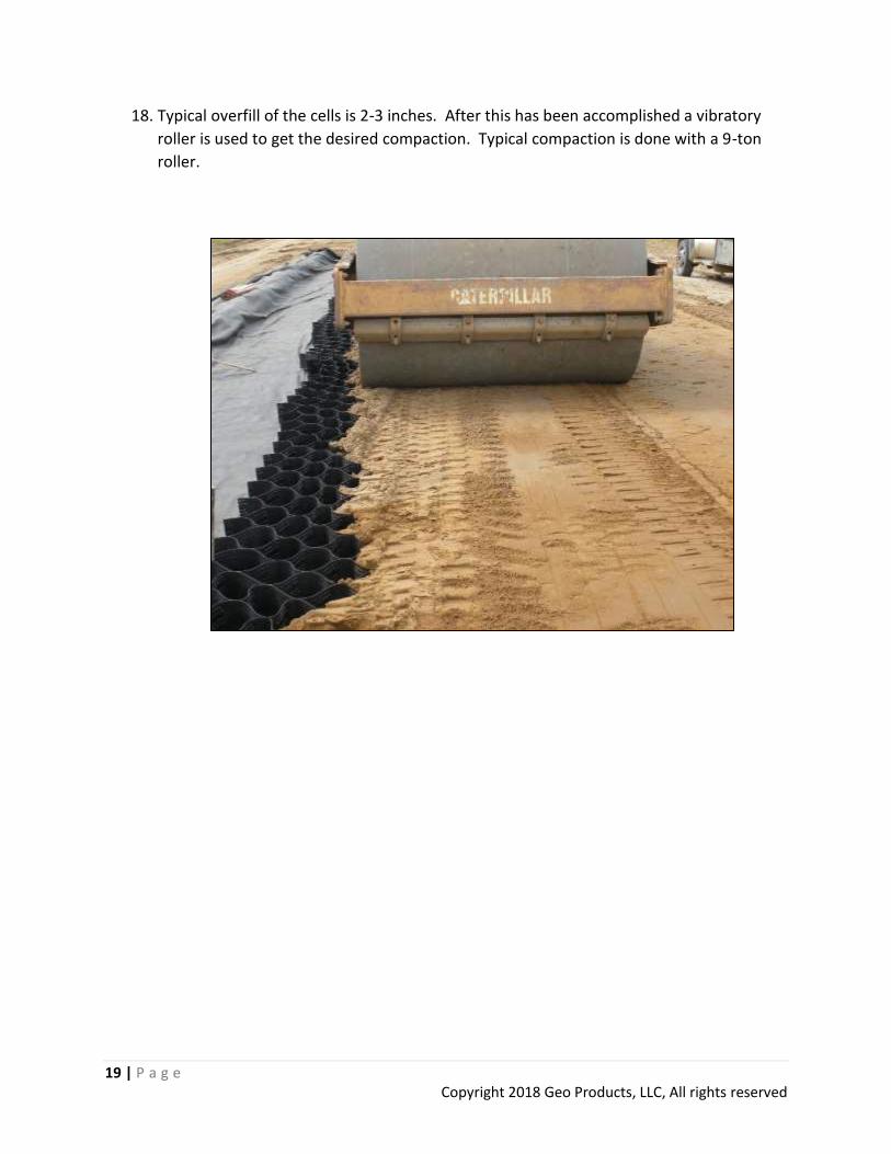
18. Typical overfill of the cells is 2-3 inches. After this has been accomplished a vibratory
roller is used to get the desired compaction. Typical compaction is done with a 9-ton
roller.

20 | P a g e Copyright 2018 Geo Products, LLC, All rights reserved
Legal Notice Geo Products, LLC provides this information only as an accommodation to our customers. No warranty or other representation regarding the suitability of the application procedures is made due to the fact that each installation has specific requirements that may not have been considered in this generalized procedure. Geo Products, LLC makes no warranties or representations regarding the suitability of its EnviroGrid® for specific uses or applications. User is strongly urged to consult its engineer and or architect prior to purchase and installation of materials set out herein.