Embed Size (px)
Citation preview
8/3/2019 Gennady Shvets et al- Excitation of accelerating plasma waves by counter-propagating laser beams
http://slidepdf.com/reader/full/gennady-shvets-et-al-excitation-of-accelerating-plasma-waves-by-counter-propagating 1/10
Excitation of accelerating plasma waves by counter-propagatinglaser beamsa…
Gennady Shvetsb) and Nathaniel J. FischPrinceton Plasma Physics Laboratory, Princeton, New Jersey 08543
Alexander Pukhov Max-Planck-Institut fu r Quantenoptik, D-85748 Garching, Germany
Received 2 November 2001; accepted 19 February 2002The conventional approach to exciting high phase velocity waves in plasmas is to employ a laser
pulse moving in the direction of the desired particle acceleration. Photon downshifting then causes
momentum transfer to the plasma and wave excitation. Novel approaches to plasma wake excitation,
colliding-beam accelerator CBA, which involve photon exchange between the long and short
counter-propagating laser beams, are described. Depending on the frequency detuning between
beams and duration L of the short pulse, there are two approaches to CBA. First approach assumes
( L2/ p). Photons exchanged between the beams deposit their recoil momentum in the plasma
driving the plasma wake. Frequency detuning between the beams determines the direction of the
photon exchange, thereby controlling the phase of the plasma wake. This phase control can be used
for reversing the slippage of the accelerated particles with respect to the wake. A variation on the
same theme, super-beatwave accelerator, is also described. In the second approach, a short pulse
with L
p
1 detuned by 2 p
from the counter-propagating beam is employed. While
parametric excitation of plasma waves by the electromagnetic beatwave at 2 p of two
co-propagating lasers was first predicted by Rosenbluth and Liu M. N. Rosenbluth and C. S. Liu,
Phys. Rev. Lett. 29, 701 1972, it is demonstrated that the two excitation beams can be
counter-propagating . The advantages of using this geometry higher instability growth rate,
insensitivity to plasma inhomogeneity are explained, and supporting numerical simulations
presented. © 2002 American Institute of Physics. DOI: 10.1063/1.1468649
I. INTRODUCTION AND MOTIVATION
Plasma is an attractive medium for ultrahigh gradient
particle acceleration because it can sustain a very high elec-
tric field, roughly limited by the cold wavebreaking field
E WBmc p / encm3V/cm, where p4 e 2n / m
is the plasma frequency and n is the electron density. To
accelerate injected particles to velocities close to the speed of
light c , this electric field has to be in a form of a fast longi-
tudinal plasma wave with phase velocity vphc. The fre-
quency of the fast plasma wave is p , and its wave number
is k p p / c . Excitation of such plasma waves can be ac-
complished by lasers or fast particle beams.1–13
Below we review the basics of linear plasma wave exci-
tation in very general terms, without restricting ourselves to
the specifics of the wakefield driver. Let us assume that
plasma electrons are subject to the electric field of the fastplasma wave E, as well as other nonlinear forces FNL , for
example, the ponderomotive force of one or more laser
pulses. The total current J J p J 2 which enters Ampere’s
law “ B(1/ c) t E(4 / c)( J p J 2) is intentionally split
into two components. The first one, J penve , where ve
is the electron fluid velocity, is driven by the electric field E
and satisfies t J pe2n E. The second component J 2 is
driven by the nonlinear ponderomotive force, or could also
represent an external current provided by injected electron
beam. Taking the time derivative of the Ampere’s law yields:
2
t 2 p0
2 Ec2 E4 J 2
t , 1
where the E term naturally vanishes in one-
dimensional 1D. One can say that the science of making a
plasma accelerator is about finding the most effective way of
producing the appropriate J 2 z( z,t ). Of course, not every
functional form of J 2 z( z, t ) is useful for making plasma
waves suitable for relativistic particle acceleration. In
the rest of this paper we concentrate on exciting J 2 z( z ,t )
J 2 z( zct ) using one or several laser pulses.
II. COMPARISON OF SINGLE-BEAM AND COLLIDINGBEAM ACCELERATORS
The simplest laser-driven plasma accelerator, which was
also the first one realized in the experiments, is the plasma
beatwave accelerator1– 6 PBWA. It employs a pair of co-
propagating laser beams with normalized vector-potentials
a0,1e A0,1 / mc 2 and frequencies 0 and 1 0 p . The
nonlinear current J 2 z is driven by the ponderomotive force of
the resulting electromagnetic beatwave according to t J 2 z
en z( a0• a1). If the two laser-beams are detuned by the
aPaper GI2 3, Bull. Am. Phys. Soc. 46, 136 2001.bInvited speaker.
PHYSICS OF PLASMAS VOLUME 9, NUMBER 5 MAY 2002
23831070-664X/2002/9(5)/2383/10/$19.00 © 2002 American Institute of Physics
Downloaded 17 Jan 2006 to 192.55.106.171. Redistribution subject to AIP license or copyright, see http://pop.aip.org/pop/copyright.jsp
8/3/2019 Gennady Shvets et al- Excitation of accelerating plasma waves by counter-propagating laser beams
http://slidepdf.com/reader/full/gennady-shvets-et-al-excitation-of-accelerating-plasma-waves-by-counter-propagating 2/10
plasma frequency p , plasma wave is resonantly excited.
The beatwave scheme was also considered by Rosenbluth
and Liu14 for plasma heating.
From Eq. 1, to excite a plasma wave one needs to
deposit momentum into the plasma. The source of this mo-
mentum is the laser. However, since the typical laser fre-
quencies 0,1
p , it is impossible for a laser photon toimpart its entire momentum to the plasma. What happens
instead is that the frequency of a laser photon is down-
shifted by the amount p , depositing the remainder momen-
tum and energy into the plasma. In the case of PBWA,
higher-frequency photons at 0 are scattered into the lower-
frequency photons at 1 0 p . Schematically, this pro-
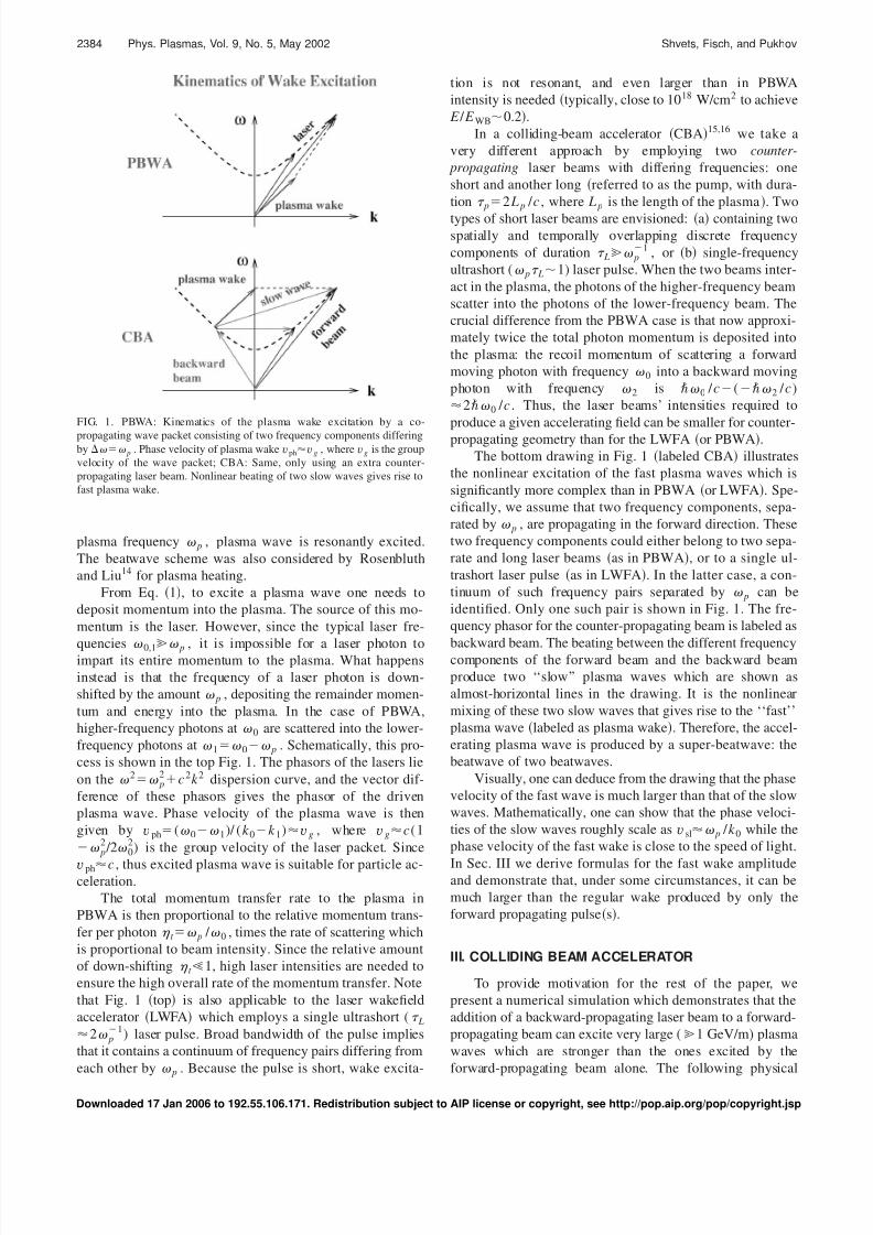
cess is shown in the top Fig. 1. The phasors of the lasers lie
on the 2 p2c 2k 2 dispersion curve, and the vector dif-
ference of these phasors gives the phasor of the driven
plasma wave. Phase velocity of the plasma wave is then
given by vph( 0 1)/ (k 0k 1)vg , where vgc(1
p2 /2 0
2) is the group velocity of the laser packet. Since
vphc , thus excited plasma wave is suitable for particle ac-celeration.
The total momentum transfer rate to the plasma in
PBWA is then proportional to the relative momentum trans-
fer per photon t p / 0 , times the rate of scattering which
is proportional to beam intensity. Since the relative amount
of down-shifting t 1, high laser intensities are needed to
ensure the high overall rate of the momentum transfer. Note
that Fig. 1 top is also applicable to the laser wakefield
accelerator LWFA which employs a single ultrashort ( L2 p
1) laser pulse. Broad bandwidth of the pulse implies
that it contains a continuum of frequency pairs differing from
each other by p . Because the pulse is short, wake excita-
tion is not resonant, and even larger than in PBWA
intensity is needed typically, close to 1018 W/cm2 to achieve
E / E WB0.2.
In a colliding-beam accelerator CBA15,16 we take a
very different approach by employing two counter-
propagating laser beams with differing frequencies: one
short and another long referred to as the pump, with dura-
tion p2 L p / c , where L p is the length of the plasma. Two
types of short laser beams are envisioned: a containing twospatially and temporally overlapping discrete frequency
components of duration L p1 , or b single-frequency
ultrashort ( p L1) laser pulse. When the two beams inter-
act in the plasma, the photons of the higher-frequency beam
scatter into the photons of the lower-frequency beam. The
crucial difference from the PBWA case is that now approxi-
mately twice the total photon momentum is deposited into
the plasma: the recoil momentum of scattering a forward
moving photon with frequency 0 into a backward moving
photon with frequency 2 is 0 / c( 2 / c)
2 0 / c . Thus, the laser beams’ intensities required to
produce a given accelerating field can be smaller for counter-
propagating geometry than for the LWFA or PBWA.
The bottom drawing in Fig. 1 labeled CBA illustrates
the nonlinear excitation of the fast plasma waves which is
significantly more complex than in PBWA or LWFA. Spe-
cifically, we assume that two frequency components, sepa-
rated by p , are propagating in the forward direction. These
two frequency components could either belong to two sepa-
rate and long laser beams as in PBWA, or to a single ul-
trashort laser pulse as in LWFA. In the latter case, a con-
tinuum of such frequency pairs separated by p can be
identified. Only one such pair is shown in Fig. 1. The fre-
quency phasor for the counter-propagating beam is labeled as
backward beam. The beating between the different frequencycomponents of the forward beam and the backward beam
produce two ‘‘slow’’ plasma waves which are shown as
almost-horizontal lines in the drawing. It is the nonlinear
mixing of these two slow waves that gives rise to the ‘‘fast’’
plasma wave labeled as plasma wake. Therefore, the accel-
erating plasma wave is produced by a super-beatwave: the
beatwave of two beatwaves.
Visually, one can deduce from the drawing that the phase
velocity of the fast wave is much larger than that of the slow
waves. Mathematically, one can show that the phase veloci-
ties of the slow waves roughly scale as vsl p / k 0 while the
phase velocity of the fast wake is close to the speed of light.
In Sec. III we derive formulas for the fast wake amplitudeand demonstrate that, under some circumstances, it can be
much larger than the regular wake produced by only the
forward propagating pulses.
III. COLLIDING BEAM ACCELERATOR
To provide motivation for the rest of the paper, we
present a numerical simulation which demonstrates that the
addition of a backward-propagating laser beam to a forward-
propagating beam can excite very large (1 GeV/m) plasma
waves which are stronger than the ones excited by the
forward-propagating beam alone. The following physical
FIG. 1. PBWA: Kinematics of the plasma wake excitation by a co-
propagating wave packet consisting of two frequency components differingby p . Phase velocity of plasma wake vphvg , where vg is the group
velocity of the wave packet; CBA: Same, only using an extra counter-
propagating laser beam. Nonlinear beating of two slow waves gives rise to
fast plasma wake.
2384 Phys. Plasmas, Vol. 9, No. 5, May 2002 Shvets, Fisch, and Pukhov
Downloaded 17 Jan 2006 to 192.55.106.171. Redistribution subject to AIP license or copyright, see http://pop.aip.org/pop/copyright.jsp
8/3/2019 Gennady Shvets et al- Excitation of accelerating plasma waves by counter-propagating laser beams
http://slidepdf.com/reader/full/gennady-shvets-et-al-excitation-of-accelerating-plasma-waves-by-counter-propagating 3/10
problem was simulated using a one-dimensional particle-in-
cell PIC code VLPL.17 An ultrashort circularly polarized
Gaussian laser pulse with duration L1.5 p1 and normal-
ized vector potential a 00.12, propagating in the positive z
direction, collides in a plasma with a long counter-
propagating pulse with a 1
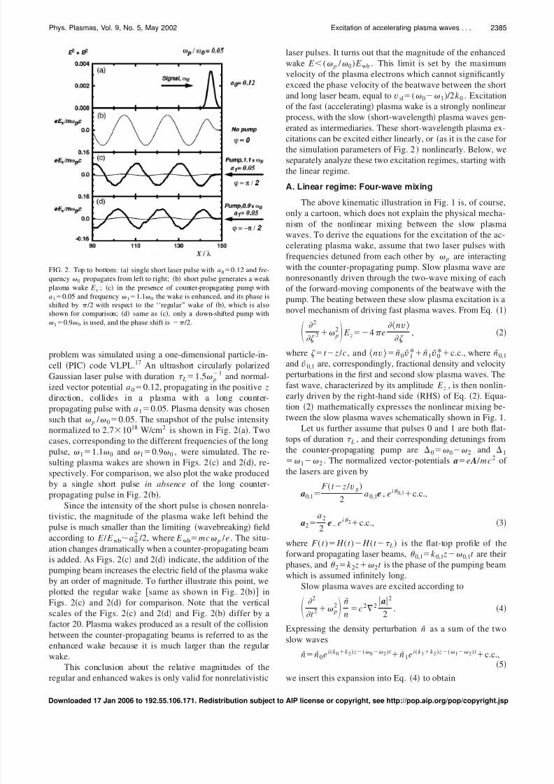
0.05. Plasma density was chosensuch that p / 00.05. The snapshot of the pulse intensity
normalized to 2.71018 W/cm2 is shown in Fig. 2a. Two
cases, corresponding to the different frequencies of the long
pulse, 11.1 0 and 10.9 0 , were simulated. The re-
sulting plasma wakes are shown in Figs. 2c and 2d, re-
spectively. For comparison, we also plot the wake produced
by a single short pulse in absence of the long counter-
propagating pulse in Fig. 2b.
Since the intensity of the short pulse is chosen nonrela-
tivistic, the magnitude of the plasma wake left behind the
pulse is much smaller than the limiting wavebreaking field
according to E / E wba02 /2, where E wbmc p / e. The situ-
ation changes dramatically when a counter-propagating beamis added. As Figs. 2c and 2d indicate, the addition of the
pumping beam increases the electric field of the plasma wake
by an order of magnitude. To further illustrate this point, we
plotted the regular wake same as shown in Fig. 2b in
Figs. 2c and 2d for comparison. Note that the vertical
scales of the Figs. 2c and 2d and Fig. 2b differ by a
factor 20. Plasma wakes produced as a result of the collision
between the counter-propagating beams is referred to as the
enhanced wake because it is much larger than the regular
wake.
This conclusion about the relative magnitudes of the
regular and enhanced wakes is only valid for nonrelativistic
laser pulses. It turns out that the magnitude of the enhanced
wake E ( p / 0) E wb . This limit is set by the maximum
velocity of the plasma electrons which cannot significantly
exceed the phase velocity of the beatwave between the short
and long laser beam, equal to vsl( 0 1)/2k 0 . Excitation
of the fast accelerating plasma wake is a strongly nonlinear
process, with the slow short-wavelength plasma waves gen-
erated as intermediaries. These short-wavelength plasma ex-
citations can be excited either linearly, or as it is the case forthe simulation parameters of Fig. 2 nonlinearly. Below, we
separately analyze these two excitation regimes, starting with
the linear regime.
A. Linear regime: Four-wave mixing
The above kinematic illustration in Fig. 1 is, of course,
only a cartoon, which does not explain the physical mecha-
nism of the nonlinear mixing between the slow plasma
waves. To derive the equations for the excitation of the ac-
celerating plasma wake, assume that two laser pulses with
frequencies detuned from each other by p are interacting
with the counter-propagating pump. Slow plasma wave are
nonresonantly driven through the two-wave mixing of each
of the forward-moving components of the beatwave with the
pump. The beating between these slow plasma excitation is a
novel mechanism of driving fast plasma waves. From Eq. 1
2
2 p
2 E z4 e nv
, 2
where t z / c, and nv n 0v 1* n 1v 0*c.c., where n 0,1
and v 0,1 are, correspondingly, fractional density and velocity
perturbations in the first and second slow plasma waves. The
fast wave, characterized by its amplitude E z , is then nonlin-
early driven by the right-hand side RHS of Eq. 2. Equa-
tion 2 mathematically expresses the nonlinear mixing be-
tween the slow plasma waves schematically shown in Fig. 1.
Let us further assume that pulses 0 and 1 are both flat-
tops of duration L , and their corresponding detunings from
the counter-propagating pump are 0 0 2 and 1
1 2 . The normalized vector-potentials ae A / mc2 of
the lasers are given by
a0,1
F t z / vg
2a 0,1ee i 0,1c.c.,
a2
a 2
2ee i 2c.c., 3
where F ( t ) H ( t ) H (t L) is the flat-top profile of the
forward propagating laser beams, 0,1k 0,1 z 0,1t are their
phases, and 2k 2 z 2t is the phase of the pumping beam
which is assumed infinitely long.
Slow plasma waves are excited according to
2
t 2 p
2 n
nc 22
a2
2. 4
Expressing the density perturbation n as a sum of the two
slow waves
n n 0e i(k 0k 2) z( 0 2)t n 1e i( k 1k 2) z( 1 2) t
c.c.,5
we insert this expansion into Eq. 4 to obtain
FIG. 2. Top to bottom: a single short laser pulse with a0
0.12 and fre-
quency 0 propagates from left to right; b short pulse generates a weak
plasma wake E x ; c in the presence of counter-propagating pump with
a10.05 and frequency 11.1 0 the wake is enhanced, and its phase is
shifted by /2 with respect to the ‘‘regular’’ wake of b, which is also
shown for comparison; d same as c, only a down-shifted pump with
10.9 0 is used, and the phase shift is /2.
2385Phys. Plasmas, Vol. 9, No. 5, May 2002 Excitation of accelerating plasma waves . . .
Downloaded 17 Jan 2006 to 192.55.106.171. Redistribution subject to AIP license or copyright, see http://pop.aip.org/pop/copyright.jsp
8/3/2019 Gennady Shvets et al- Excitation of accelerating plasma waves by counter-propagating laser beams
http://slidepdf.com/reader/full/gennady-shvets-et-al-excitation-of-accelerating-plasma-waves-by-counter-propagating 4/10
n 0
n
k 0k 22c2a 0a2
202 p
2
,
n 1
n
k 1k 22c2a 1a2
212 p
2
. 6
Expanding the velocity perturbations in the slow waves in
the same way as it was done in Eq. 5, we calculate v 0 and
v 1 from the continuity equation
v 00
k 0k 2
n 0
n, v 1
1
k 1k 2
n 1
n. 7
We are now in a position of calculating nv
nv
nca 0a 1
*F 2 t z / vg
2e i( 0 1)
0
k 0k 2
1
k 1k 2
k 0k 22k 1k 2
2c3a 22
20
2
p2
1
2
p2
c.c. 8
Note that the expression in front of the square brackets is
proportional to the direct beatwave strength in the plasma
beatwave accelerator. The term in the square brackets which
we label is proportional to the super-beatwave strength.
Whenever the term in the square brackets exceeds unity, the
super-beatwave results in a larger accelerating wake than the
usual beatwave. A more compact simplified expression for
can be obtained by noting that in a tenuous plasma with
p 2 , k 0 ,k 1k 2 2 / c, yielding
8a 22 2
3
p3 01 p
3
0
2 p
2
1
2 p
2 . 9
The magnitude of is, roughly, determined by the quantity
8a 22 23 / p
3 . Equation 9 is only valid when 0,12 p
2 ,
which physically means that none of the slow waves are
resonantly excited.
Substituting nv into Eq. 2, we calculate the electric
field behind the forward-moving beatwave in the region t
z / vg L
eE z
mc p
p La 0a1
4 cos 0 1
2a0a 1a22 2
3 L
p2
01 p
3
0
2
p2
1
2
p2
cos 0 1, 10
where 0 1(k 0k 1) z pt is the phase of the fast
plasma wave. Note that the phase velocity of the fast plasma
wave which is produced by the super-beatwave is the same
as that of the regular beatwave, and equal to the group ve-
locity of the forward-moving laser packet. The phase of the
fast plasma wake is determined by the relative phases of the
forward-moving laser pulses. The phase of the counter-
propagating pump does not matter at all, while its amplitude
affects the enhancement coefficient of the super-beatwave ,
thereby determining the amplitude of the fast wave as well.
Also, according to Eq. 10, fast wave generation in the col-
liding beam accelerator is a four-wave process.
Note that in the particular case of 010 wakefield
vanishes. Since 1 0 p , this case corresponds to 2 00.5 p . Therefore, the scattering of the photons from
beam 0 into beam 2 proceeds at the same rate as the scatter-
ing of the beam 2 into beam 1, and the overall momentum
deposition into the plasma vanishes.
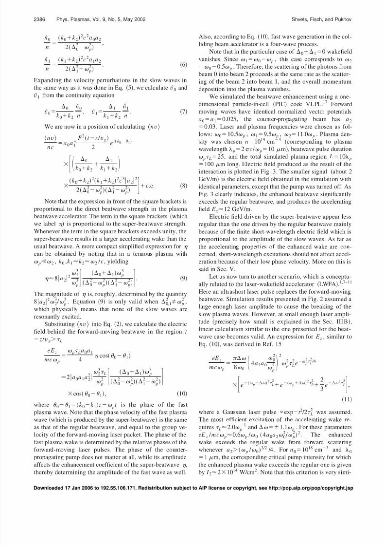
We simulated the beatwave enhancement using a one-dimensional particle-in-cell PIC code VLPL.17 Forward
moving waves have identical normalized vector potentials
a0a 10.025, the counter-propagating beam has a 2
0.03. Laser and plasma frequencies were chosen as fol-
lows: 010.5 p , 19.5 p , 211.0 p . Plasma den-
sity was chosen n1019 cm3 corresponding to plasma
wavelength p2 c / p10 m, beatwave pulse duration
p L25, and the total simulated plasma region L10 p
100 m long. Electric field produced as the result of the
interaction is plotted in Fig. 3. The smaller signal about 2
GeV/m is the electric field obtained in the simulation with
identical parameters, except that the pump was turned off. As
Fig. 3 clearly indicates, the enhanced beatwave significantly
exceeds the regular beatwave, and produces the accelerating
field E z12 GeV/m.
Electric field driven by the super-beatwave appear less
regular than the one driven by the regular beatwave mainly
because of the finite short-wavelength electric field which is
proportional to the amplitude of the slow waves. As far as
the accelerating properties of the enhanced wake are con-
cerned, short-wavelength excitations should not affect accel-
eration because of their low phase velocity. More on this is
said in Sec. V.
Let us now turn to another scenario, which is conceptu-
ally related to the laser-wakefield accelerator LWFA.
1,7–11
Here an ultrashort laser pulse replaces the forward-moving
beatwave. Simulation results presented in Fig. 2 assumed a
large enough laser amplitude to cause the breaking of the
slow plasma waves. However, at small enough laser ampli-
tude precisely how small is explained in the Sec. III B,
linear calculation similar to the one presented for the beat-
wave case becomes valid. An expression for E z , similar to
Eq. 10, was derived in Ref. 15
eE z
mc p
8 0 4a2a 0
02
p2
2
p2 L
2 e p2
L2
/4
e( p )2 L2e( p )2 L2 23
e 2 L2 ,
11
where a Gaussian laser pulse expt 2 /2 L2 was assumed.
The most efficient excitation of the accelerating wake re-
quires L2.0 p1 and 1.1 p . For these parameters
eE z / mc p0.6 p / 0 (4a 0a2 02 / p
2)2. The enhanced
wake exceeds the regular wake from forward scattering
whenever a 2( p / 0)3/2 /4. For n 01018 cm3 and 0
1 m, the corresponding critical pump intensity for which
the enhanced plasma wake exceeds the regular one is given
by I 221014 W/cm2. Note that this criterion is very simi-
2386 Phys. Plasmas, Vol. 9, No. 5, May 2002 Shvets, Fisch, and Pukhov
Downloaded 17 Jan 2006 to 192.55.106.171. Redistribution subject to AIP license or copyright, see http://pop.aip.org/pop/copyright.jsp
8/3/2019 Gennady Shvets et al- Excitation of accelerating plasma waves by counter-propagating laser beams
http://slidepdf.com/reader/full/gennady-shvets-et-al-excitation-of-accelerating-plasma-waves-by-counter-propagating 5/10
lar to 1, where is given by Eq. 9. This is not surpris-
ing: in both cases fast plasma waves are produced via four-
wave mixing.
B. Nonlinear regime: Particle trapping
The above picture of a four-wave process resulting in the
excitation of a fast wave via the super-beatwave mechanism
is only true when all waves in question are linear. Fast
plasma wave always remains linear because its amplitude is
below the wavebreaking limit. Slow waves which beat
against each other to produce the super-beatwave break
much easier, their breaking limiting the fast wave amplitude.
The ease with which the slow waves break is related to their
low phase velocity. Indeed, breaking of a particular wave
with phase velocity vph occurs when plasma electrons are
accelerated to velocities vvph . After wavebreaking, par-
ticle motion is determined solely by the ponderomotive beat-
wave force between counter-propagating beams. Space
charge force becomes smaller than the ponderomotive force,
and can be neglected.
The most interesting and easy-to-understand regime cor-
responds to the single-frequency short pulse of duration L / p which is strong enough to cause wavebreaking. The
incidence of wavebreaking is, approximately, determined bythe ratio of the bounce frequency B2 0a 0a2 and the
plasma frequency. In the strongly nonlinear regime B2
p2 , and the space-charge force which is proportional to
p2 can be neglected in comparison with the ponderomotive
force which is proportional to B2 . In this regime plasma
wave amplitude is estimated16 as
eE z
mc p
P z
mcsin p sign B
0 sin p , 12
where P z is the average momentum transferred to the
plasma by the laser pulse. The physics of this momentum
transfer can be visualized by plotting the electron phase
space at different times: Before the arrival of the short pulse,
near the maximum of the short pulse, and right after the
wavebreaking Fig. 4.
Numerical simulations indicate that the largest momen-
tum gain is achieved for the frequency detuning Band pulse duration L2/ B . For those parameters, plasma
electrons execute about half a bounce in the ponderomotive
potential, and leave the ponderomotive bucket with average
velocity v zc B / 0 . The nonlinear current J 2 zenv z is
then inserted into Eq. 2 to yield Eq. 12.
IV. PARAMETRIC EXCITATION OF PLASMA WAVESBY 2 P DETUNING
In the previous section we considered two approaches to
excitation of fast plasma waves: One involved two pulses
moving in the forward direction and another in the backward
direction super-beatwave approach, and the other one re-
quired a short ( L2/ p) forward-moving pulse and a
backward-moving pulse CBA approach. The beatwave ap-
proach is complex for two reasons: a Three laser pulses are
needed, and b laser pulses have to be detuned by the
plasma frequency. Most laser systems have a fairly small
bandwidth several percent. This reduces the resonant
plasma density and the accelerating gradient. For example, if the fractional frequency detuning is / 03%, then the
resonant plasma density for a 1 m laser is n p
1018 cm3. Since the accelerating gradient is limited by
wavebreaking to only E z( p / 0)mc p / e, the accelerat-
ing gradient in of a super-beatwave accelerator in such
plasma is only 3 GeV/m.
Single-pulse CBA can also be challenging with presently
available lasers because it requires a very short pulse. For
example, assuming n p1019 cm3 and p2 p1 yields the
full width, half maximum FWHM of only 14 fs. While
such short pulse lasers do exist,18 they are not widely avail-
able and are, typically, low power.
FIG. 3. Accelerating field E z produced by the regularbeatwave without pump small wave and with pump
a20.03 large wave. Beatwave parameters: 010.5 p , 1 0 p , p L25, pump frequency:
211 p , plasma density: n1019 cm3.
2387Phys. Plasmas, Vol. 9, No. 5, May 2002 Excitation of accelerating plasma waves . . .
Downloaded 17 Jan 2006 to 192.55.106.171. Redistribution subject to AIP license or copyright, see http://pop.aip.org/pop/copyright.jsp

8/3/2019 Gennady Shvets et al- Excitation of accelerating plasma waves by counter-propagating laser beams
http://slidepdf.com/reader/full/gennady-shvets-et-al-excitation-of-accelerating-plasma-waves-by-counter-propagating 6/10
All these limitations, and also the simultaneous avail-
ability of Nd:Yag (11.06 m) and Ti:S (00.8 m)
laser systems in a number of laboratories compels one to
think of other possible techniques of wake excitation. A
novel scheme19 has been recently suggested: parametric ex-
citation of accelerating plasma waves using counter-
propagating laser beams detuned by, approximately, 2 p .
Short-pulse duration no longer is required to be comparable
to p1 ; in fact, it is advantageous to use significantly longer
pulses with p L25. From experimental standpoint, this
could be a fairly attractive regime: if 0 12 p , then
the desired plasma density n p2.51019 cm3, and the re-
quired pulse duration L25 p1 corresponds to 160 fsFWHM. Such plasma and laser parameters are achievable,
making the practical implementation of the scheme feasible.
We simulated the interaction between a trapezoidally-
shaped short pulse and a long counter-propagating laser
beam using a one-dimensional version of a VLPL17 particle-
in-cell code. The amplitude of the circularly-polarized short
pulse is a 00.1, its rise and fall times are 150 / c and
50 / c , respectively, and the flat portion is 150 / c , where
02 c / 0 . The amplitude of the counter-propagating la-
ser beam is a10.015, rise and fall times are 200 / c, and
the flat portion is 1000 / c . Frequency of the counter-
propagating beam is chosen to be 10.8 0 and the plasma
frequency p0.1 0 .
Intensity profile of the short pulse is plotted in Fig. 5a
85 laser periods after it entered the plasma and interactedwith the counter-propagating pumping beam. Uniform
plasma extends from Z 5 m to Z 90 m. Assuming for
FIG. 4. Left to right: Electron phase space a before the arrival of short pulse; b near maximum of short pulse; c at wavebreaking. Rapid current jolt
developing at wavebreaking drives the enhanced wake behind the short pulse.
FIG. 5. Short laser pulse of trapezoidal shape rise
150 / c , drop50 / c , flat150 / c) with ampli-
tude a00.1 and frequency 0 collides with counter-
propagating pump with a10.015 and 1 02 pgenerating an accelerating wake E z . For 01 m and
p / 00.1, a short laser pulse intensity; b acceler-
ating wakefield E z .
2388 Phys. Plasmas, Vol. 9, No. 5, May 2002 Shvets, Fisch, and Pukhov
Downloaded 17 Jan 2006 to 192.55.106.171. Redistribution subject to AIP license or copyright, see http://pop.aip.org/pop/copyright.jsp
8/3/2019 Gennady Shvets et al- Excitation of accelerating plasma waves by counter-propagating laser beams
http://slidepdf.com/reader/full/gennady-shvets-et-al-excitation-of-accelerating-plasma-waves-by-counter-propagating 7/10
simplicity that 01 m, the peak intensity of the short
pulse is 2.71016 W/cm2. As the short pulse interacts with
the long pump, an accelerating wake grows from the front of
the short pulse towards the back, as shown in Fig. 5b. The
peak accelerating gradient is about 10 GeV/m. Wakefield de-
creases for Z 20 m because the two pulses met at Z
20 m.
Periodicity of the plasma wake is 1002 c / p .
Therefore, the phase velocity of this wake is c , and it is
suitable for particle acceleration. The spiky appearance of
the wake is due to the simultaneous generation of the slow
plasma waves, just as it was the case in Fig. 3. The same
simulation was repeated without the low-intensity counter-
propagating beam, and the accelerating field was much
smaller. This simulation confirms that the counter-
propagating laser beam initiates a parametric instability
which amplifies a very small initial wakefield. To our knowl-
edge, this is the first direct PIC simulation of the plasma
wake generation by two counter-propagating lasers detuned
by 2 p . It confirms the effect which was previously mod-
eled analytically and using a simplified time-averaged par-
ticle simulation.19 In the co-propagating geometry and at
much higher intensity, parametric wake excitation at 2 p detuning was recently simulated by Ren et al.20
That a plasma wave can be driven unstable by the 2 pbeatwave was originally proposed by Rosenbluth and Liu,14
who calculated the growth rate of a fast plasma wave RL
pa 0a 1 /2 co-propagating lasers. This instability is high-
order, with growth rate scaling as the product of laser ampli-
tudes. Thus, for pump waves of sub-relativistic intensity, i.e.,
a 0 ,a11, this decay instability is too slow to be of great
practical interest. Simulation results presented in Fig. 5 indi-
cates that the counter-propagating geometry i results in a
much larger growth rate, and ii produces fast acceleratingplasma waves, just as the co-propagating geometry would.
Both effects were overlooked in the original calculation of
Rosenbluth and Liu. Thus, Fig. 5 illustrates a totally different
laser-plasma instability. Below we explain the basic physics
of this instability.
To describe the one-dimensional plasma motion in the
field of two laser beams, we use the Lagrangian approach.21
Plasma electron position is characterized by its time-
dependent displacement ( z0 , t ) from the equilibrium posi-
tion z0 . By definition, z z0 and ( z 0 ,t )0. Elec-
tron equation of motion is then given by
¨ z p
2 z
emc
v Bc
2
2“ a2, 13
where the second term in the left-hand side LHS of Eq.
13 is the restoring force of the ion background which is
assumed immobile. The RHS of Eq. 13 is the ponderomo-
tive force, and a a0 a1 is the total vector potential. The
expression for the ponderomotive force was derived using
conservation of the canonical momenta P x and P y of the
electron. Conservation of P x and P y follows from the as-
sumption that both laser fields are given by plane waves
which do not depend on x or y : a0,1a 0,1(e exp(i 0,1)
c.c.), where e()(e xie y)/2, 0k 0 z 0t , and 1
k 1 z 1t . In nonrelativistic case, this translates into a
simple expression for vc a which was used to derive the
equation for the ponderomotive force. We are interested in
the cross-term in the expansion a2 a02
a122 a0• a1
which is responsible for the beatwave excitation of the
plasma.
Noting that 0 1(k 0k 1) z t 2k 0 z t ,
where 0 1 , we obtain from Eq. 13
¨ p2 ik 0c2a 0a 1e2ik 0 e i[ t 2k 0 z0]
c.c. 14
Due to the nonlinear term exp2ik 0 in the RHS of Eq. 14,
several modes of plasma oscillation can become coupled. We
concentrate on the coupling between two particular plasma
modes with wave numbers k s2k 0k p and k f k p p / c . Here k s and k f are the wave numbers of the slow
and fast plasma waves, respectively. These two waves are
strongly coupled to each other when 2 p .
If a 0 is constant, any two waves with k s and k f satisfy-
ing k sk f 2k 0 are strongly coupled. In reality, however, a 0
represents the vector potential of an ultrashort laser pulse
propagating with the group velocity vgc . Therefore, a 0
a0( t z / vg)a0( t z0 / c) since the laser envelop is
longer than the wavelength. This selects the wave number of
the fast wave k f p / c and, therefore, the wavelength of the
slow wave k s2k 0k p . Numerical results presented in Fig.
5 also reveal the strong excitation of a plasma wave with k
p / c .
To describe the instability, we assume the most general
two-wave ansatz for an electron displacement
A f sink p z0 pt f
A s sink s z0 pt s , 15
where A f ( f ) and A s ( s) are the amplitudes phases of
the fast and slow plasma waves. Of interest to plasma accel-
erators is, of course, only the fast plasma wave with phase
velocity close to the speed of light. For simplicity, in the
analytic calculation we assume monochromatic laser
waves. Short-pulse effects are numerically treated later on
see Fig. 6.
We proceed by substituting from Eq. 15 into the non-
linear term exp2ik 0 in the RHS of Eq. 14 and using the
Bessel identity e i sin k J k ( )eik . Equation 14 then be-
comes
2
t 2 p
2 ik 0c 2a 0a 1k ,l1k l J k 2k 0 A f J l2k 0 A s
e ik [ k p z0 pt f ]e il [ k s z0 pt s]e i[ t 2k 0 z0]
c.c., 16
where 2 p . A set of purely time-dependent
equations can now be obtained by separating the z0 depen-
dent terms on both sides of Eq. 16. Thus, substituting Eq.
15 into LHS of Eq. 16 and matching the corresponding
harmonics of k p z0 and k s z0 on both sides of the equation, we
can write for the (k 0,l1) and (k 1,l0) terms the fol-
lowing:
2389Phys. Plasmas, Vol. 9, No. 5, May 2002 Excitation of accelerating plasma waves . . .
Downloaded 17 Jan 2006 to 192.55.106.171. Redistribution subject to AIP license or copyright, see http://pop.aip.org/pop/copyright.jsp
8/3/2019 Gennady Shvets et al- Excitation of accelerating plasma waves by counter-propagating laser beams
http://slidepdf.com/reader/full/gennady-shvets-et-al-excitation-of-accelerating-plasma-waves-by-counter-propagating 8/10
t
B2
4 pG A f , Assin , 17
k 0 A f
pt
B2
4J 02k 0 A f J 12k 0 A scos , 18
k 0 A s
pt
B2
4J 12k 0 A f J 02k 0 A scos , 19
where s f /2 t , B24a0a 1 0
2 / p2 is the
square of the electron bounce frequency in the optical lattice
created by the interference of the counter-propagating lasers,
and
G A f , As J 02k 0 A f J 12k 0 A s
k 0 A f
J 12k 0 A f J 02k 0 A s
k 0 A s
.
The general case of nonzero laser detuning and large
wave amplitudes were analyzed in Ref. 19. Here we restrict
ourselves to the resonant ( 0) and linear (2k 0 A f ,s1)
case, for which Eqs. 17–19 are simplified to yield ˙
B2 /4( A f / A s A s / A f )sin , A f B
2 A s /4 cos and A s
B2 A s /4 cos . Since the phase rapidly locks at 0, the
two plasma waves, fast and slow, feed on each other and
exponentiate with the growth rate i 02a 1a0 / p .
The instability mechanism is easy to understand. Fast
plasma wave which varies as n f cos p(t z / c) modulatesthe ponderomotive force which oscillates as f zcos(2k 0 z
2 pt ) to resonantly drive the slow wave which varies as
n scos(2k 0k p) z pt . In its turn, the slow wave modu-
lates the ponderomotive force, driving the fast wave and
completing the feedback loop of the instability. Instability
persists until the wavebreaking of the slow wave. Numerical
simulations indicate that the amplitude of the fast wave is
limited by approximately E maxmc p2 /2 0e.
Using a one-dimensional time-averaged particle code,22
we simulated excitation of the fast and slow plasma waves
by a short slightly chirped under-compressed pulse with the
wavelength 00.8 m which collides with a longer 1
1 m pulse in a 1019 cm3 plasma. These wavelengths
correspond to widely available laser systems Ti:S and Nd-
glass, and the plasma density was chosen to satisfy 0 12.35 p . Other laser parameters are as follows: a 0
0.15 exp 2 /2 L2 with L25 160 fs FWHM and
d / d 9.5103 p 3% bandwidth. The initial fast
plasma wave e 0103 and a 10.0165 have been assumed.
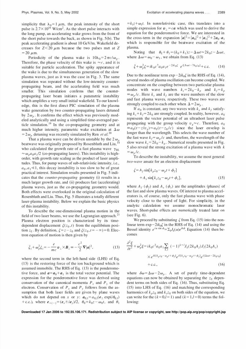
Simulation results are shown in Fig. 6, where we observe the
excitation of both the fast and the slow plasma waves.
Despite the small amplitudes of both forward and back-
ward pulse, and despite the fact that the duration of the short
pulse is too long for the efficient wake generation, we find
that a significant fast plasma wave E z7 GeV/m is excited.
Parameters used in the simulation are fairly standard for Ti:S
and Nd-Glass systems.
Simulation results presented in Fig. 6 point to another
important aspect of the parametric excitation of fast plasma
waves using counter-propagating laser beams. Despite the
fact that the frequency detuning between the two laser beams
differs from 2 p 2.35 p in the simulation, instability
still proceeds. This means that the growth rate of the insta-
bility is not very sensitive to variations in laser detuning or in
the plasma density. This is quite advantageous since plasma
density may not be known to high accuracy, and may vary
across the interaction region.
V. UTILITY OF COLLIDING BEAM ACCELERATOR
One obvious benefit of the counter-propagating geom-
etry is that very large accelerating wakes of order 10
GeV/m can be produced with moderate-intensity lasers ( I
1016 W/cm2). Another, less obvious benefit is the ability to
control the phase of the accelerating wake. One observes
from Fig. 2 that by changing the frequency of the long pulsefrom 11.1 0 Fig. 2c to 10.9 0 Fig. 2d, the
phase of the wake is changed by . Thus, one can
envision a ‘‘plasma linac’’ which consists of independently
phase-controlled acceleration sections, separated by drift
spaces.
Numerical implementation of the plasma linac concept is
shown in Fig. 7. Collision of a short ‘‘timing beam’’ TB of
duration L p1 and normalized vector potential a 00.08
with a long ‘‘pumping beam’’ PB a10.012 is modeled
using a one-dimensional 1D version of PIC simulation
code VLPL.17 Figure 7a illustrates the temporal profile of
the PB, which moves to the left; Figs. 7b and 7c are the
snapshots of the generated plasma wake and the phase spaceof accelerated electrons, which are continuously injected
with initial energy 10 MeV electrons; Fig. 7d shows the
evolution of the TB as it moves through the plasma. To show
how one can control the phase and the magnitude of the
resulting plasma wake, we split the PB into two sections:
The leading section of duration t 15002 / 0 , where
1.7 p , and the trailing section t 32502 / 0 ,
where 1.7 p . These two pump beam sections are
separated by the middle section of duration t 2t 3 , where
the pump is switched off.
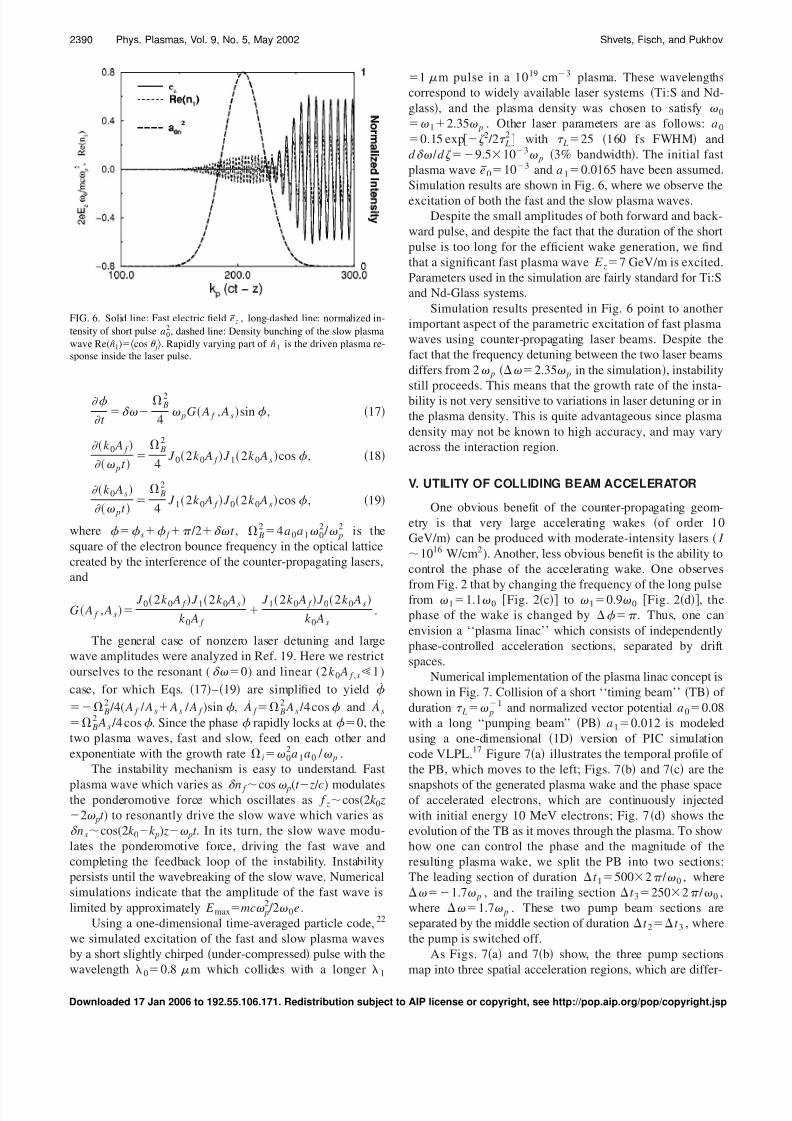
As Figs. 7a and 7b show, the three pump sections
map into three spatial acceleration regions, which are differ-
FIG. 6. Solid line: Fast electric field e z , long-dashed line: normalized in-
tensity of short pulse a02
, dashed line: Density bunching of the slow plasma
wave Re(n 1)cos j. Rapidly varying part of n 1 is the driven plasma re-
sponse inside the laser pulse.
2390 Phys. Plasmas, Vol. 9, No. 5, May 2002 Shvets, Fisch, and Pukhov
Downloaded 17 Jan 2006 to 192.55.106.171. Redistribution subject to AIP license or copyright, see http://pop.aip.org/pop/copyright.jsp
8/3/2019 Gennady Shvets et al- Excitation of accelerating plasma waves by counter-propagating laser beams
http://slidepdf.com/reader/full/gennady-shvets-et-al-excitation-of-accelerating-plasma-waves-by-counter-propagating 9/10
ent from each other in TB dynamics, magnitude, and phase
of the plasma wake. In the leading region the pump beam has
higher frequency and energy flows into the TB, amplifying it.
A strong plasma wake with the peak accelerating gradient of
8 GeV/m is induced. The middle region is void of the pump.
Here the TB interacts with the plasma through the usual
LWFA mechanism only, producing a weak, 1 GeV/m, ac-
celerating wake. In this region the energy of the injected
electrons does not significantly change, as seen from Fig.
7c. When the trailing low-frequency part of the pump
collides with the TB, the energy flows from the TB into the
PB, Fig. 7d. Again, a strong plasma wake is induced, Fig.
7b. This wake, however, is shifted in phase by withrespect to the leading region. As a result, electrons which
gained energy in the leading region are decelerated in the
trailing region, Fig. 7c. This shows that both amplitude and
phase of the enhanced plasma wake can be controlled by
shaping the long low-intensity pump beam.
Note that the accelerating wake in Fig. 7b looks some-
what irregular due to the presence of the slow short-
wavelength plasma waves. Nevertheless, the particle phase
space does not show any irregularity. Relativistic particles
experience a much smoother accelerating field because the
phase velocity of the slow plasma waves is much smaller
than the speed of light.
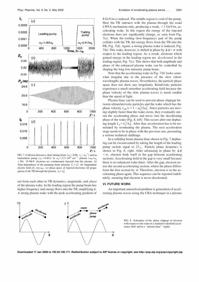
Plasma linac can be used to prevent phase slippage be-
tween ultrarelativistic particles and the wake which has the
phase velocity vph / c1 p2 /2 0
2 . Since particles are mov-
ing slightly faster than the wake crests, they eventually out-
run the accelerating phase and move into the decelerating
phase of the wake Fig. 8, left. This occurs after one dephas-
ing length L d p3 / 0
2 . After that, acceleration has to be ter-
minated by terminating the plasma. The next acceleration
stage needs to be in phase with the previous one, presenting
a serious technical challenge.
In a colliding beam plasma linac shown in Fig. 7 dephas-
ing can be circumvented by taking the length of the leading
pump section equal to 2 L d . Particle phase dynamics isshown in Fig. 8, right. After advancing in phase by , electron finds itself in the gap between accelerating
sections. Accelerating field in the gap is very small because
there is no enhanced wake there. After the gap, electron en-
ters the second accelerating section, where the phase differs
from the first section by . Therefore, electron is in the ac-
celerating phase again. This sequence can be repeated indefi-
nitely, ensuring that electron is never decelerated.
VI. FUTURE WORK
An important unresolved problem is generation of accel-
erating plasma waves using the CBA technique in a plasma
FIG. 7. Collision between a short timing beam a00.08, L p1 and an
intermittent pump (a10.012) in n02.51018 cm3 plasma ( 0 / p20). 10 MeV electrons are continuously injected into the plasma. a
Time-dependence of the pumping beam intensity I 1a12; b longitudinal
electric field eE z / mc 0 ; c phase space of injected electrons; d propa-
gation of the TB through the plasma, I 0a02.
FIG. 8. Schematic of the phase slippage of electron
with respect to the wake in a standard wakefield accel-
erator left and in a ‘‘plasma linac’’ right.
2391Phys. Plasmas, Vol. 9, No. 5, May 2002 Excitation of accelerating plasma waves . . .
Downloaded 17 Jan 2006 to 192.55.106.171. Redistribution subject to AIP license or copyright, see http://pop.aip.org/pop/copyright.jsp
8/3/2019 Gennady Shvets et al- Excitation of accelerating plasma waves by counter-propagating laser beams
http://slidepdf.com/reader/full/gennady-shvets-et-al-excitation-of-accelerating-plasma-waves-by-counter-propagating 10/10
channel. Plasma channels are important for guiding both
long and short laser beams. Moreover, transversely inhomo-
geneous plasma may impart an unusual structure to the ac-
celerating field with a local minimum on axis. This may
result in advantageous transverse focusing properties of the
wake, especially in the context of the colliding-beam
injector.16
ACKNOWLEDGMENTS
This work was supported by the DOE Division of High
Energy Physics and the Presidential Early Career Award for
Scientists and Engineers.
1T. Tajima and J. M. Dawson, Phys. Rev. Lett. 43, 267 1979.2Y. Kitagawa, T. Matsumoto, T. Minamihata, K. Sawai, K. Matsuo, K.
Mima, K. Nishihara, H. Azechi, K. A. Tanaka, H. Takabe, and S. Nakai,
Phys. Rev. Lett. 68, 48 1992.3C. E. Clayton, K. A. Marsh, A. Dyson, M. Everett, A. Lal, W. P. Leemans,
R. Williams, and C. Joshi, Phys. Rev. Lett. 70, 37 1993.4M. Everett, A. Lal, D. Gordon, C. E. Clayton, K. A. Marsh, and C. Joshi,
Nature London 368, 527 1994.5N. A. Ebrahim, J. Appl. Phys. 76, 7645 1994.6
F. Amiranoff, J. Ardonceau, M. Bercher, D. Bernard, B. Cros et al., in Advanced Accelerator Concepts, AIP Conf. Proc. edited by P. Schoessow
American Institute Physics, New York, 1995, Vol. 335, p. 612.
7L. M. Gorbunov and V. I. Kirsanov, Sov. Phys. JETP 66, 290 1987.8E. Esarey, A. Ting, P. Sprangle, and G. Joyce, Comments Plasma Phys.
Controlled Fusion 12, 191 1989.9F. Amiranoff, S. Baton, D. Bernard, B. Cross et al., Phys. Rev. Lett. 81,
995 1998.10K. Nakajima, T. Kawakubo, H. Nakanishi, A. Ogata et al., in Advanced
Accelerator Concepts, AIP Conf. Proc. edited by P. Schoessow American
Institute Physics, New York, 1995, Vol. 335, p. 145.11P. Sprangle, B. Hafizi, J. R. Penano, R. F. Hubbard et al., Phys. Rev. E 63,
056405 2001.12P. Chen, J. M. Dawson, R. W. Huff, and T. Katsouleas, Phys. Rev. Lett. 54,
693 1985.13E. Esarey, P. Sprangle, J. Krall, and A. Ting, IEEE Trans. Plasma Sci. 24,
252 1996, and references therein.14M. N. Rosenbluth and C. S. Liu, Phys. Rev. Lett. 29, 701 1972.15G. Shvets, N. J. Fisch, A. Pukhov, and J. Meyer-ter-Vehn, Phys. Rev. E 60,
2218 1999.16G. Shvets, N. J. Fisch, and A. Pukhov, IEEE Trans. Plasma Sci. 28, 1194
2000.17A. Pukhov and J. Meyer-ter-Vehn, Bull. Am. Phys. Soc. 41, 1502 1996.18T. Brabec and F. Krausz, Rev. Mod. Phys. 72, 545 2000.19G. Shvets and N. J. Fisch, Phys. Rev. Lett. 86, 3328 2001.20C. Ren, E. S. Dodd, D. Gordon, and W. B. Mori, Phys. Rev. Lett. 85, 3412
2000.21
J. Dawson, Phys. Rev. 113, 383 1959.22G. Shvets, N. J. Fisch, A. Pukhov, and J. Meyer-ter-Vehn, Phys. Rev. Lett.
81, 4879 1998.
2392 Phys. Plasmas, Vol. 9, No. 5, May 2002 Shvets, Fisch, and Pukhov