Embed Size (px)
Citation preview
Genius 1051 User Manual
2015 © Peak Scientific - Rev 2C – 21/01/15
Genius 1051 User Manual
Page 2 2015 © Peak Scientific - Rev 2C – 21/01/15
Contents
Change History 4
How to use this Manual 4
Introduction 5
Warranties and Liabilities 6
Safety Notices 7
Symbols 7
Safety Notice to Users 7
Technical Specification 8
Environment 8
Generator Outlets 8
Electrical Requirements 8
General 8
Unpacking 9
Installation 10
Generator Environment 10
General Dimensions 10
Removal of Transit Brackets 11
Unit Controls 12
Rear Connections 13
Drain Connection 13
Electrical Connection 14
Start-up Sequence 16
Connecting to the Application 16
Tubing Lengths 17
Gas Flow Combinations 18
Air Selector Switch 18
IMPORTANT DOCUMENTS 19
Normal Operation 20
On Demand Gas 20
Generator Cycling 20
Unusual Operation 20
Service Requirements 21
Genius 1051 User Manual
Page 3 2015 © Peak Scientific - Rev 2C – 21/01/15
Service Schedule 21
Service Indication 21
Stage 1 21
Stage 2 22
Service Indication Reset 22
Service Plans 22
Cleaning 22
High Duty Indication 23
High Duty Indication Reset 23
Indication of Fault 23
Trouble Shooting 24
Genius 1051 User Manual
Page 4 2015 © Peak Scientific - Rev 2C – 21/01/15
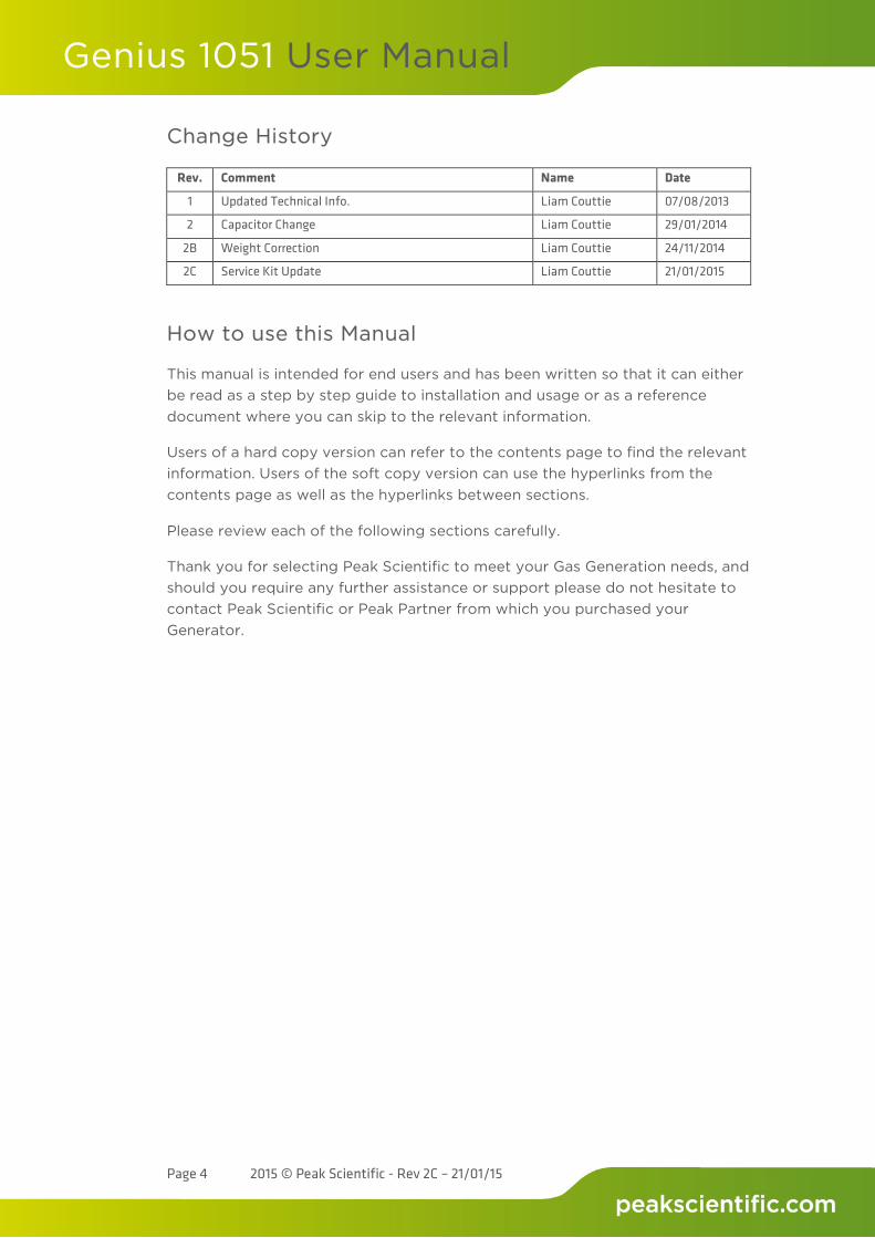
Change History
Rev. Comment Name Date
1 Updated Technical Info. Liam Couttie 07/08/2013
2 Capacitor Change Liam Couttie 29/01/2014
2B Weight Correction Liam Couttie 24/11/2014
2C Service Kit Update Liam Couttie 21/01/2015
How to use this Manual
This manual is intended for end users and has been written so that it can either be read as a step by step guide to installation and usage or as a reference document where you can skip to the relevant information.
Users of a hard copy version can refer to the contents page to find the relevant information. Users of the soft copy version can use the hyperlinks from the contents page as well as the hyperlinks between sections.
Please review each of the following sections carefully.
Thank you for selecting Peak Scientific to meet your Gas Generation needs, and should you require any further assistance or support please do not hesitate to contact Peak Scientific or Peak Partner from which you purchased your Generator.

Genius 1051 User Manual
Page 5 2015 © Peak Scientific - Rev 2C – 21/01/15
Introduction
The Genius 1051 has been developed to cater for systems which require a Nitrogen gas supply.
This model provides a source of Nitrogen gas with other features including:
• Small in size – fits under a standard lab bench • Quiet in operation – noise level of 54 db(A) • Anti- vibration – maximum reduction of vibration • Service indication – allowing you to plan your maintenance and keep
your application uptime at a maximum • Improved drainage – reduction of moisture carry over and thus
increased reliability • Re- heat technology – improves membrane performance and reliability • Robust control system – improves safety and reliability of units
With the Genius 1051 based on proven technology, it selectively removes oxygen, moisture and other gases to leave clean, dry, phthalate free Nitrogen. Two internal air compressors make this unit independent from in- house air supplies and fitted castors allow the user to easily position the unit in the lab.
To ensure this Generator model meets our high expectations with regards to reliability and performance, we have tested this new model extensively at our manufacturing plant and with end users around the world to ensure reliability and longevity of the system.
Genius 1051 User Manual
Page 6 2015 © Peak Scientific - Rev 2C – 21/01/15
Warranties and Liabilities
1. The Company warrants that it has title to the Goods. 2. Subject to the provisions of this clause the Company warrants that the
Goods shall comply in all material respects with any specification referred to in the Order Confirmation (as the same may be amended) and shall, subject thereto, be free from defects in material and workmanship for the lesser of a period of twelve months from the date of delivery or thirteen months from the date of dispatch from the factory.
3. Save as provided in this clause and except where the Goods are sold to a person dealing as a consumer (within the meaning of the Unfair Contract Terms Act 1977) all warranties, conditions or other terms implied by statute or common law are hereby expressly excluded save to the extent they may not be lawfully excluded. When the Goods are sold to a consumer within the meaning of the Unfair Contract Terms Act 1977 their statutory rights are not affected by the provisions of this clause.
4. In the event of the Customer making a claim in respect of any defect in terms of clause 2 hereof the Customer must.
1. Reasonably satisfy the Company that the Goods have been properly installed, commissioned, stored, serviced and used and without prejudice to the generality of the foregoing that any defect is not the direct or indirect result of lack of repair and/or servicing, incorrect repair and/or servicing, use of wrong materials and/or incorrect spare parts
2. Allow the company to inspect the Goods and/or any installation and any relevant packaging as and when reasonably required by the Company.
5. Subject to the Company being notified of any defect as is referred to in sub-clause 2 hereof within a reasonable time of it becoming apparent and subject always to the terms of sub-clause 4 hereof, the Company shall, in its option, replace or repair the defective Goods or refund a proportionate part of the Price. The Company shall have no further liability to the Customer (save as mentioned in sub-clause 6 hereof).
6. The Company shall be liable to indemnify the Customer in respect of any claim for death or personal injury to any person in so far as such is attributable to the negligence or breach of duty of the Company or any failure by the Company to comply with the provisions of sub-clause 2 hereof.
7. Save as provided in sub-clause 2 hereof the Company shall not be liable in respect of any claim by the Customer for costs, damages, loss or expenses (whether direct, indirect, consequential or otherwise) or indemnity in any respect howsoever arising including, but not by way of limitation, liability arising in negligence (other than pursuant to clause 6 above) that may be suffered by the Customer or any third party.
Genius 1051 User Manual
Page 7 2015 © Peak Scientific - Rev 2C – 21/01/15
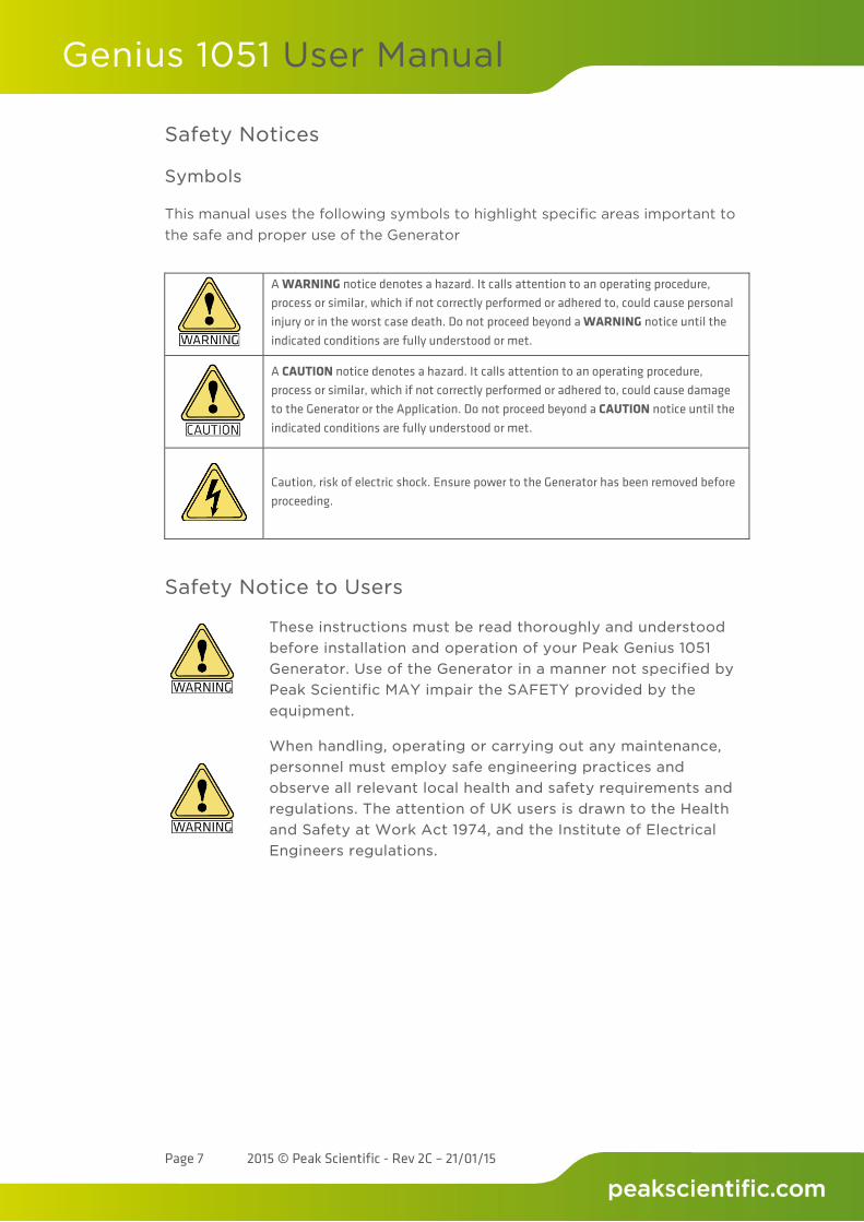
Safety Notices
Symbols
This manual uses the following symbols to highlight specific areas important to the safe and proper use of the Generator
Safety Notice to Users
These instructions must be read thoroughly and understood before installation and operation of your Peak Genius 1051 Generator. Use of the Generator in a manner not specified by Peak Scientific MAY impair the SAFETY provided by the equipment.
When handling, operating or carrying out any maintenance, personnel must employ safe engineering practices and observe all relevant local health and safety requirements and regulations. The attention of UK users is drawn to the Health and Safety at Work Act 1974, and the Institute of Electrical Engineers regulations.
A WARNING notice denotes a hazard. It calls attention to an operating procedure, process or similar, which if not correctly performed or adhered to, could cause personal injury or in the worst case death. Do not proceed beyond a WARNING notice until the indicated conditions are fully understood or met.
A CAUTION notice denotes a hazard. It calls attention to an operating procedure, process or similar, which if not correctly performed or adhered to, could cause damage to the Generator or the Application. Do not proceed beyond a CAUTION notice until the indicated conditions are fully understood or met.
Caution, risk of electric shock. Ensure power to the Generator has been removed before proceeding.
Genius 1051 User Manual
Page 8 2015 © Peak Scientific - Rev 2C – 21/01/15
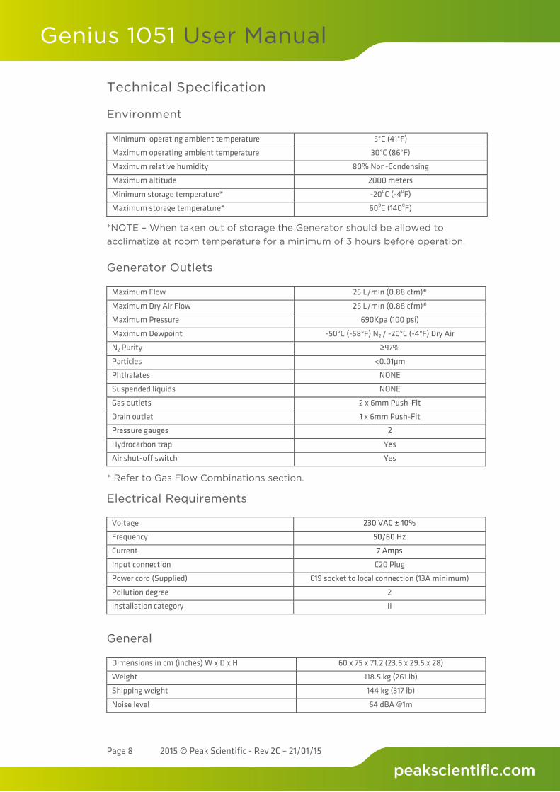
Technical Specification
Environment
Minimum operating ambient temperature 5°C (41°F)
Maximum operating ambient temperature 30°C (86°F)
Maximum relative humidity 80% Non-Condensing
Maximum altitude 2000 meters
Minimum storage temperature* -20oC (-4oF)
Maximum storage temperature* 60oC (140oF)
*NOTE – When taken out of storage the Generator should be allowed to acclimatize at room temperature for a minimum of 3 hours before operation.
Generator Outlets
Maximum Flow 25 L/min (0.88 cfm)*
Maximum Dry Air Flow 25 L/min (0.88 cfm)*
Maximum Pressure 690Kpa (100 psi)
Maximum Dewpoint -50°C (-58°F) N2 / -20°C (-4°F) Dry Air
N2 Purity ≥97%
Particles <0.01µm
Phthalates NONE
Suspended liquids NONE
Gas outlets 2 x 6mm Push-Fit
Drain outlet 1 x 6mm Push-Fit
Pressure gauges 2
Hydrocarbon trap Yes
Air shut-off switch Yes
* Refer to Gas Flow Combinations section.
Electrical Requirements
Voltage 230 VAC ± 10%
Frequency 50/60 Hz
Current 7 Amps
Input connection C20 Plug
Power cord (Supplied) C19 socket to local connection (13A minimum)
Pollution degree 2
Installation category II
General
Dimensions in cm (inches) W x D x H 60 x 75 x 71.2 (23.6 x 29.5 x 28)
Weight 118.5 kg (261 lb)
Shipping weight 144 kg (317 lb)
Noise level 54 dBA @1m

Genius 1051 User Manual
Page 9 2015 © Peak Scientific - Rev 2C – 21/01/15
Unpacking
Although Peak Scientific takes every precaution with safe transit and packaging, it is advisable to fully inspect the unit for any sign of transit damage.
Check ‘SHOCKWATCH’ label for signs of rough handling prior to un-packing –
Any damage should be reported immediately to the carrier and Peak Scientific or the Peak Partner from where the unit was purchased.
Follow the unpacking instructions posted on the side of the crate. It will require two people to remove the unit from the shipping crate and to manoeuvre the Generator onto the floor.
Please save the product packaging for storage or future shipment of the Generator.
Note: Included with the Generator is a “Fittings Kit” containing mains power leads for UK, EU and US also all the required fittings. Be careful not to discard these with the packaging.
Genius 1051 User Manual
Page 10 2015 © Peak Scientific - Rev 2C – 21/01/15
Installation
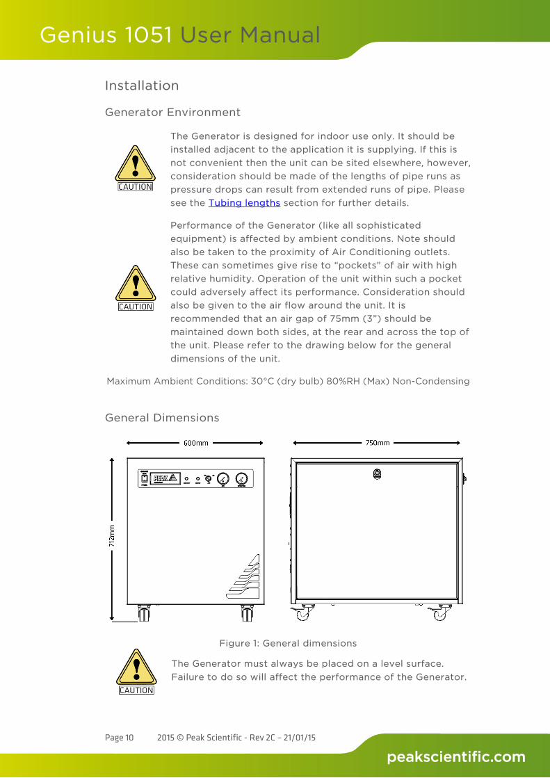
Generator Environment
The Generator is designed for indoor use only. It should be installed adjacent to the application it is supplying. If this is not convenient then the unit can be sited elsewhere, however, consideration should be made of the lengths of pipe runs as pressure drops can result from extended runs of pipe. Please see the Tubing lengths section for further details.
Performance of the Generator (like all sophisticated equipment) is affected by ambient conditions. Note should also be taken to the proximity of Air Conditioning outlets. These can sometimes give rise to “pockets” of air with high relative humidity. Operation of the unit within such a pocket could adversely affect its performance. Consideration should also be given to the air flow around the unit. It is recommended that an air gap of 75mm (3”) should be maintained down both sides, at the rear and across the top of the unit. Please refer to the drawing below for the general dimensions of the unit.
Maximum Ambient Conditions: 30°C (dry bulb) 80%RH (Max) Non-Condensing
General Dimensions
Figure 1: General dimensions
The Generator must always be placed on a level surface. Failure to do so will affect the performance of the Generator.
Genius 1051 User Manual
Page 11 2015 © Peak Scientific - Rev 2C – 21/01/15
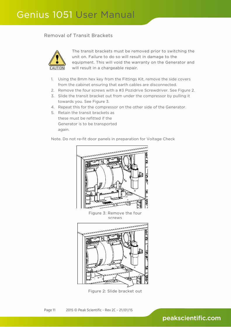
Removal of Transit Brackets
The transit brackets must be removed prior to switching the unit on. Failure to do so will result in damage to the equipment. This will void the warranty on the Generator and will result in a chargeable repair.
1. Using the 8mm hex key from the Fittings Kit, remove the side covers
from the cabinet ensuring that earth cables are disconnected. 2. Remove the four screws with a #3 Pozidrive Screwdriver. See Figure 2. 3. Slide the transit bracket out from under the compressor by pulling it
towards you. See Figure 3. 4. Repeat this for the compressor on the other side of the Generator. 5. Retain the transit brackets as
these must be refitted if the Generator is to be transported again.
Note. Do not re-fit door panels in preparation for Voltage Check
Figure 3: Remove the four screws
Figure 2: Slide bracket out
Genius 1051 User Manual
Page 12 2015 © Peak Scientific - Rev 2C – 21/01/15
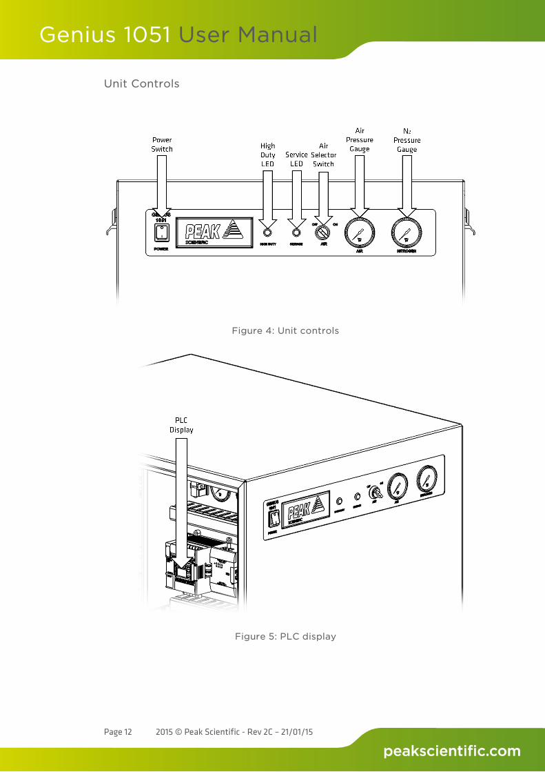
Unit Controls
Figure 4: Unit controls
Figure 5: PLC display
Genius 1051 User Manual
Page 13 2015 © Peak Scientific - Rev 2C – 21/01/15
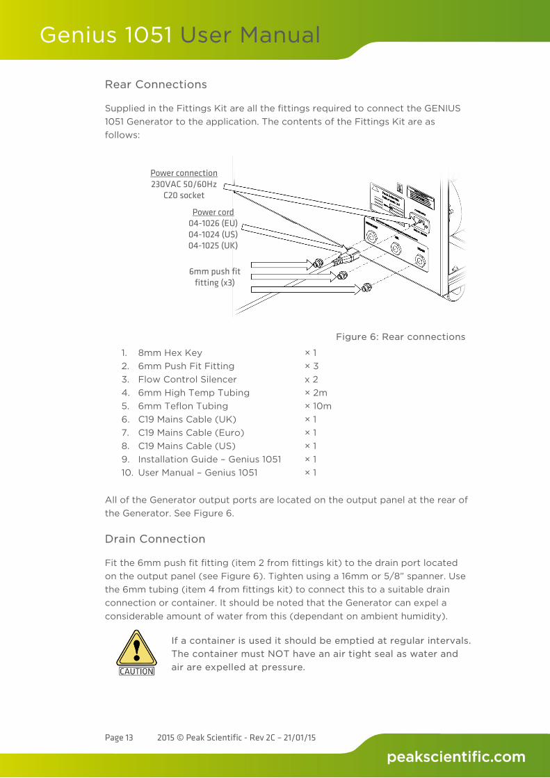
Rear Connections
Supplied in the Fittings Kit are all the fittings required to connect the GENIUS 1051 Generator to the application. The contents of the Fittings Kit are as follows:
1. 8mm Hex Key × 1 2. 6mm Push Fit Fitting × 3 3. Flow Control Silencer x 2 4. 6mm High Temp Tubing × 2m 5. 6mm Teflon Tubing × 10m 6. C19 Mains Cable (UK) × 1 7. C19 Mains Cable (Euro) × 1 8. C19 Mains Cable (US) × 1 9. Installation Guide – Genius 1051 × 1 10. User Manual – Genius 1051 × 1
All of the Generator output ports are located on the output panel at the rear of the Generator. See Figure 6.
Drain Connection
Fit the 6mm push fit fitting (item 2 from fittings kit) to the drain port located on the output panel (see Figure 6). Tighten using a 16mm or 5/8” spanner. Use the 6mm tubing (item 4 from fittings kit) to connect this to a suitable drain connection or container. It should be noted that the Generator can expel a considerable amount of water from this (dependant on ambient humidity).
If a container is used it should be emptied at regular intervals. The container must NOT have an air tight seal as water and air are expelled at pressure.
Figure 6: Rear connections
6mm push fit fitting (x3)
Power connection 230VAC 50/60Hz
C20 socket
Power cord 04-1026 (EU) 04-1024 (US) 04-1025 (UK)
Genius 1051 User Manual
Page 14 2015 © Peak Scientific - Rev 2C – 21/01/15
Electrical Connection
Connect the Generator to a 230 volt single-phase supply using the power cord provided. If the appropriate power cord is not supplied; a new plug, rated to at least 13 amps, can be sourced.
This unit is classified as SAFETY CLASS 1. THIS UNIT MUST BE EARTHED. Before connecting the unit to the mains supply, please check the information on the serial plate. The mains supply must be of the stated AC voltage and frequency.
EARTH/GROUND (E):- Green & Yellow or Green
LIVE (L):- Brown or Black
Neutral (N):- Blue or White
Our electrical requirements are 230VAC nominal +/- 10%. This means that the Generator can accommodate transients between 207VAC and 253VAC. However, running continuously at voltages less than 220V is not recommended and extended periods at these extremes can have a detrimental effect on the operation and life of the Generator.
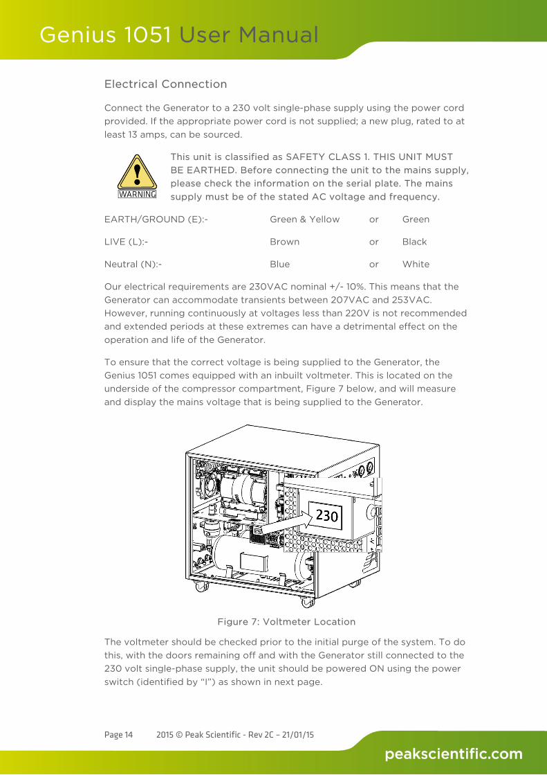
To ensure that the correct voltage is being supplied to the Generator, the Genius 1051 comes equipped with an inbuilt voltmeter. This is located on the underside of the compressor compartment, Figure 7 below, and will measure and display the mains voltage that is being supplied to the Generator.
Figure 7: Voltmeter Location
The voltmeter should be checked prior to the initial purge of the system. To do this, with the doors remaining off and with the Generator still connected to the 230 volt single-phase supply, the unit should be powered ON using the power switch (identified by “I”) as shown in next page.
Genius 1051 User Manual
Page 15 2015 © Peak Scientific - Rev 2C – 21/01/15
Do not touch anything inside the Generator whilst the side panels are removed and the mains power is connected to the unit
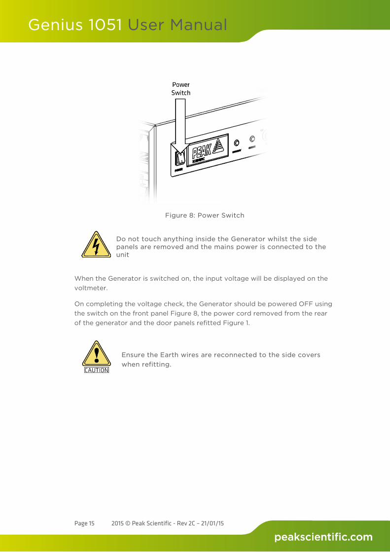
When the Generator is switched on, the input voltage will be displayed on the voltmeter.
On completing the voltage check, the Generator should be powered OFF using the switch on the front panel Figure 8, the power cord removed from the rear of the generator and the door panels refitted Figure 1.
Ensure the Earth wires are reconnected to the side covers when refitting.
Figure 8: Power Switch
Genius 1051 User Manual
Page 16 2015 © Peak Scientific - Rev 2C – 21/01/15
Start-up Sequence
Before the Generator is connected to the application, the Generator should be operated in isolation (i.e. not connected to the application) for thirty minutes. This is to ensure any impurities present are purged from the system. Failure to do this may harm the application.
The Generator should be re-connected to the mains and switched on.
Pressure will start to build in the internal storage tanks which can be monitored by watching the output pressure gauge on the front panel. This will climb to the factory set pressure as noted in the specifications.
Once this pressure is reached, the compressors will continue to run until the internal tank upper pressure limit is reached and the compressor has run for a period of at least two and a half minutes.
The compressors will then rest until the internal tank lower pressure limits is reached. Once this limit is reached the compressors will switch back on again. This compressor cycling is normal and will continue throughout the operation of the Generator.
When the system has been operated for a period of 30 minutes, all the internal pipe-work and storage tanks will have been purged with Nitrogen.
The Generator is now purged and the tubes can be connected at the rear of the unit.
Connecting to the Application
Once the initial purge run of 30 minutes has completed the Generator is now ready to be connected to the application.
Attach the 6mm elbow fittings to the outlets of the Generator (see Figure 6). Using the 6mm tubing supplied, connect the outlet of the Generator to the inlet on the application.
If you require more tubing than is supplied please refer to the Tubing Lengths section.
Once the tubing is connected to the application, please ensure that it is thoroughly checked for being leak-tight. Even the slightest leak in the gas supply between the Generator and the application can lead to a reduction in efficiency.
Genius 1051 User Manual
Page 17 2015 © Peak Scientific - Rev 2C – 21/01/15
Tubing Lengths
The diameter of the tubing which will be connected to the gas outlet is important and is determined by the length of tubing required. Failure to follow these recommendations could lead to accelerated compressor wear.
< 10 meters: Use 6/4 (6mm O/D, 4mm I/D) P.T.F.E. tubing. > 10 - 40 meters: Use 10/8 (10mm O/D, 8mm I/D). Tubing and fittings not
supplied in the fittings kit. > 40 metres: Please contact Peak Scientific with the relevant distance
and we will calculate the flow resistance and the tubing size required.
A combination of 6/4 and 10/8 tubing may be used to ensure that there is no large diameter tubing within the lab (i.e. for the first 20 meters from the Generator use 10/8 and the final 10 meters to the application use 6/4 tubing). Keep the connections and bends to a minimum. The imperial equivalents are: 6/4 = 1/4” O/D, 3/16” I/D. 10/8 = 3/8” O/D, 5/16” I/D.
Genius 1051 User Manual
Page 18 2015 © Peak Scientific - Rev 2C – 21/01/15
Gas Flow Combinations
The Genius 1051 is configured in such a way that it is possible to change the flow ratio of Nitrogen and Dry Air.
The System is capable of providing a variety of Nitrogen and Dry Air combinations, the table below illustrates some typical flow combinations.
The figures shown above should be viewed as an approximation, in that, so long as the combined sum results in a total of 25Lpm, the combinations are numerous.
The gas flow ratios are automatically controlled by the demand requirements of the instrument being supplied.
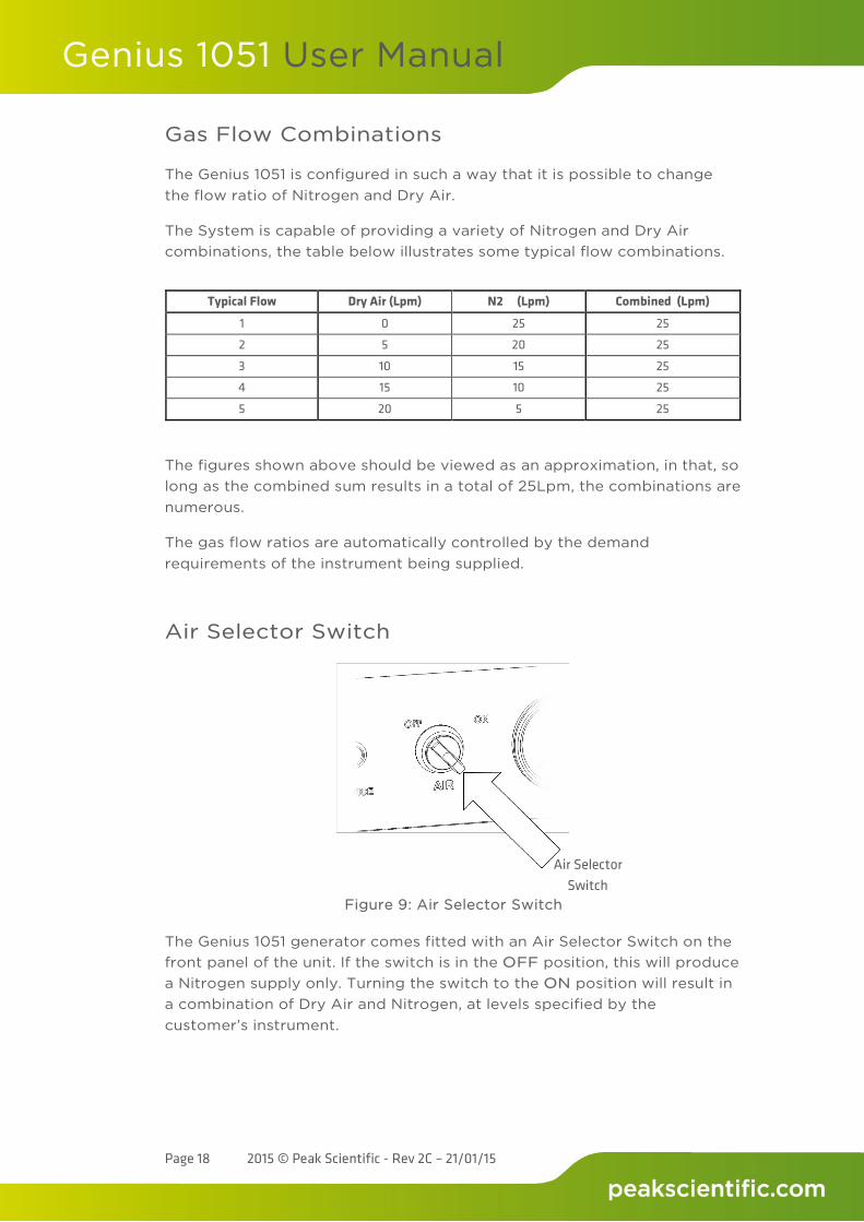
Air Selector Switch
The Genius 1051 generator comes fitted with an Air Selector Switch on the front panel of the unit. If the switch is in the OFF position, this will produce a Nitrogen supply only. Turning the switch to the ON position will result in a combination of Dry Air and Nitrogen, at levels specified by the customer’s instrument.
Typical Flow Dry Air (Lpm) N2 (Lpm) Combined (Lpm)
1 0 25 25
2 5 20 25
3 10 15 25
4 15 10 25
5 20 5 25
Air Selector Switch
Figure 9: Air Selector Switch
Genius 1051 User Manual
Page 19 2015 © Peak Scientific - Rev 2C – 21/01/15
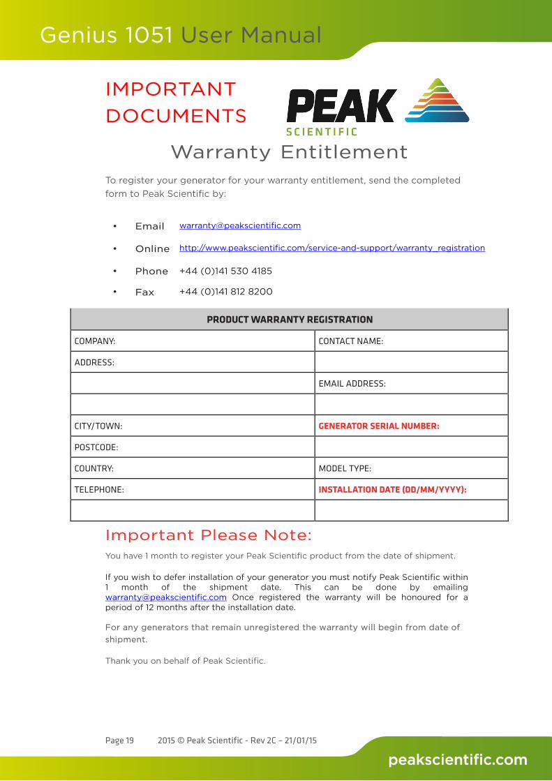
IMPORTANT DOCUMENTS
Warranty Entitlement To register your generator for your warranty entitlement, send the completed form to Peak Scientific by:
• Email [email protected]
•
Online
http://www.peakscientific.com/service-and-support/warranty_registration
• •
Phone
Fax
+44 (0)141 530 4185
+44 (0)141 812 8200
PRODUCT WARRANTY REGISTRATION
COMPANY:
CONTACT NAME:
ADDRESS:
EMAIL ADDRESS:
CITY/TOWN:
GENERATOR SERIAL NUMBER:
POSTCODE:
COUNTRY:
MODEL TYPE:
TELEPHONE:
INSTALLATION DATE (DD/MM/YYYY):
Important Please Note: You have 1 month to register your Peak Scientific product from the date of shipment.
If you wish to defer installation of your generator you must notify Peak Scientific within 1 month of the shipment date. This can be done by emailing [email protected] Once registered the warranty will be honoured for a period of 12 months after the installation date. For any generators that remain unregistered the warranty will begin from date of shipment.
Thank you on behalf of Peak Scientific.
Genius 1051 User Manual
Page 20 2015 © Peak Scientific - Rev 2C – 21/01/15
Normal Operation
The Genius 1051 Gas Generator is designed specifically to minimize operator involvement. Given that the system is installed as described in earlier sections and is serviced in accordance with the specified maintenance recommendations (see Service Requirements), then it should simply be a matter of turning the Generator on when it is required.
The Generator will automatically produce the factory set flow and pressure as detailed in the Technical Specifications.
On Demand Gas
The Generator produces gas on demand. If the application is operating and requires a gas flow, the Generator will supply this to suit the requirements of the application. If the application requirement for gas stops, the Generator will also stop, once it has reached its upper set limit in the internal storage tanks. If the demand from the application starts again, the Generator will detect the demand for gas and will automatically start again to suit the demand.
If the customer requires an AIR supply in conjunction with the N2 supply, this is activated by rotating the ON/OFF switch on the front fascia. The combination can be any value so long as the sum is 25l/min in total, e.g. 13 N2/12 Air or 10 N2/15 Air etc.
Generator Cycling
The Generator is designed for the internal compressors to cycle. This cycling reduces the duty (run time) on the compressors. The rate at which they cycle will be dependent on the gas required to satisfy the demand of the application. If the application demands the maximum gas flow of the Generator, the compressor duty will be higher, (the rest period in the compressor cycle will be shorter). If the application demand is lower than the maximum gas flow, then the duty on the compressors will decrease, (the rest period in the compressor cycle will be longer). If the Generator is installed in an extreme environment or is subjected to low supply voltage or high altitude the compressors may undergo periods where they do not cycle (see High Duty Indication).
Unusual Operation
If at any time the Generator begins to emit excessive noise or vibration, then it should be switched off and you should contact Peak Scientific or the Peak Partner from which the Generator has been purchased.
Genius 1051 User Manual
Page 21 2015 © Peak Scientific - Rev 2C – 21/01/15
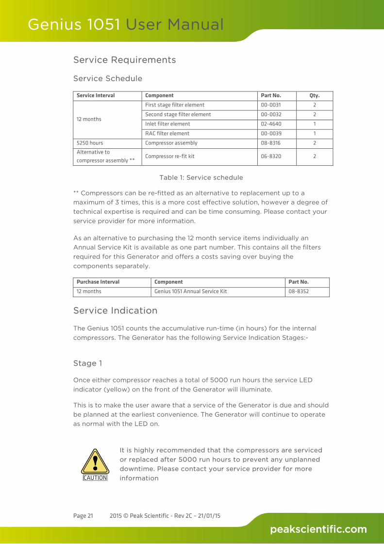
Service Requirements
Service Schedule
Service Interval Component Part No. Qty.
12 months
First stage filter element 00-0031 2
Second stage filter element 00-0032 2
Inlet filter element 02-4640 1
RAC filter element 00-0039 1
5250 hours Compressor assembly 08-8316 2
Alternative to compressor assembly **
Compressor re-fit kit 06-8320 2
Table 1: Service schedule
** Compressors can be re-fitted as an alternative to replacement up to a maximum of 3 times, this is a more cost effective solution, however a degree of technical expertise is required and can be time consuming. Please contact your service provider for more information.
As an alternative to purchasing the 12 month service items individually an Annual Service Kit is available as one part number. This contains all the filters required for this Generator and offers a costs saving over buying the components separately.
Purchase Interval Component Part No. 12 months Genius 1051 Annual Service Kit 08-8352
Service Indication
The Genius 1051 counts the accumulative run-time (in hours) for the internal compressors. The Generator has the following Service Indication Stages:-
Stage 1
Once either compressor reaches a total of 5000 run hours the service LED indicator (yellow) on the front of the Generator will illuminate.
This is to make the user aware that a service of the Generator is due and should be planned at the earliest convenience. The Generator will continue to operate as normal with the LED on.
It is highly recommended that the compressors are serviced or replaced after 5000 run hours to prevent any unplanned downtime. Please contact your service provider for more information
Genius 1051 User Manual
Page 22 2015 © Peak Scientific - Rev 2C – 21/01/15
Stage 2
If the service is not completed the Generator will continue to run. Once the compressor reaches a total of 5250 run hours, the service LED indicator (yellow) will start to flash.
This is to make the user aware that the service of the Generator is now overdue and must be completed immediately to ensure the continuous trouble free operation of the Generator.
Once 5250 hours is reached it is highly likely that the compressors will fail in the near future. Please contact your service provider as soon as possible to arrange a service or replacement of your compressors.
Service Indication Reset
Once the service has been completed the Service Indication LED can be reset in the main control PLC. This will be performed by the Peak Service Engineer or trained service representative that completes the service operation.
Service Plans
Peak Scientific offer two service plans. The Complete Service Plan, specifically designed for Generators operated in critical environments, also includes full breakdown cover, guaranteed response times and Generator upgrades if available. Our Standard Service Plan, covering the basic needs of our Generators, features special deals on spare parts and breakdowns.
If you want to know more about our Service Plan options and how we ensure that your instrument can run with the maximum uptime and performance, please contact us at [email protected]
Cleaning
Clean the outside of the Generator only using warm soapy water and a clean damp cloth. Ensure the cloth is thoroughly rung out to remove excess fluid prior to use.
Cleaning should only be undertaken with the power switched off and the power cord removed from the rear of the Generator.
Genius 1051 User Manual
Page 23 2015 © Peak Scientific - Rev 2C – 21/01/15
Under no circumstances should any solvents or abrasive cleaning solutions be used as these can contain fumes that could be harmful to the Generator.
High Duty Indication
The Genius 1051 has a ‘HIGH DUTY’ indicator on the front panel. This indicator monitors the running condition of the internal compressors and illuminates when they have been operating continually for a period of 8 hours.
There are a number of extreme conditions that can affect the duty cycling of the compressors inside the Genius 1051. These extremes include very high ambient temperatures, low supply voltages, a very high flow requirement and locations of high altitude. Any one of these or a combination of a number of these extremes can be evident in a customer site.
While the Genius 1051 Generator is designed to operate fully in these conditions it should be noted that the effect of these extremes can force the compressors to run continually. The compressors are fully capable of running continually with no detrimental effect. However it should be noted that if this is the case it will increase their duty and they will reach the 5000 hour recommended service interval quicker.
High Duty Indication Reset
If the compressors have been operating continually for a period of 8 hours the indicator light will be illuminated. Once the compressors return to a cycling mode the indicator light will automatically switch off. There is no manual intervention required.
Indication of Fault
In most installations the ‘HIGH DUTY’ indicator will never be illuminated. If your Genius 1051 Generator has been operating for a significant period of time, then suddenly develops a ‘HIGH DUTY’ indication with no apparent change in environmental conditions or flow requirements, it may be indicative of a problem with the system such as an external leak or imminent compressor failure.
If this is the case you should contact Peak Scientific or your service provider.
It should be noted that the Generator will continue to operate so long as it can maintain pressure during this indication.
Genius 1051 User Manual
Page 24 2015 © Peak Scientific - Rev 2C – 21/01/15
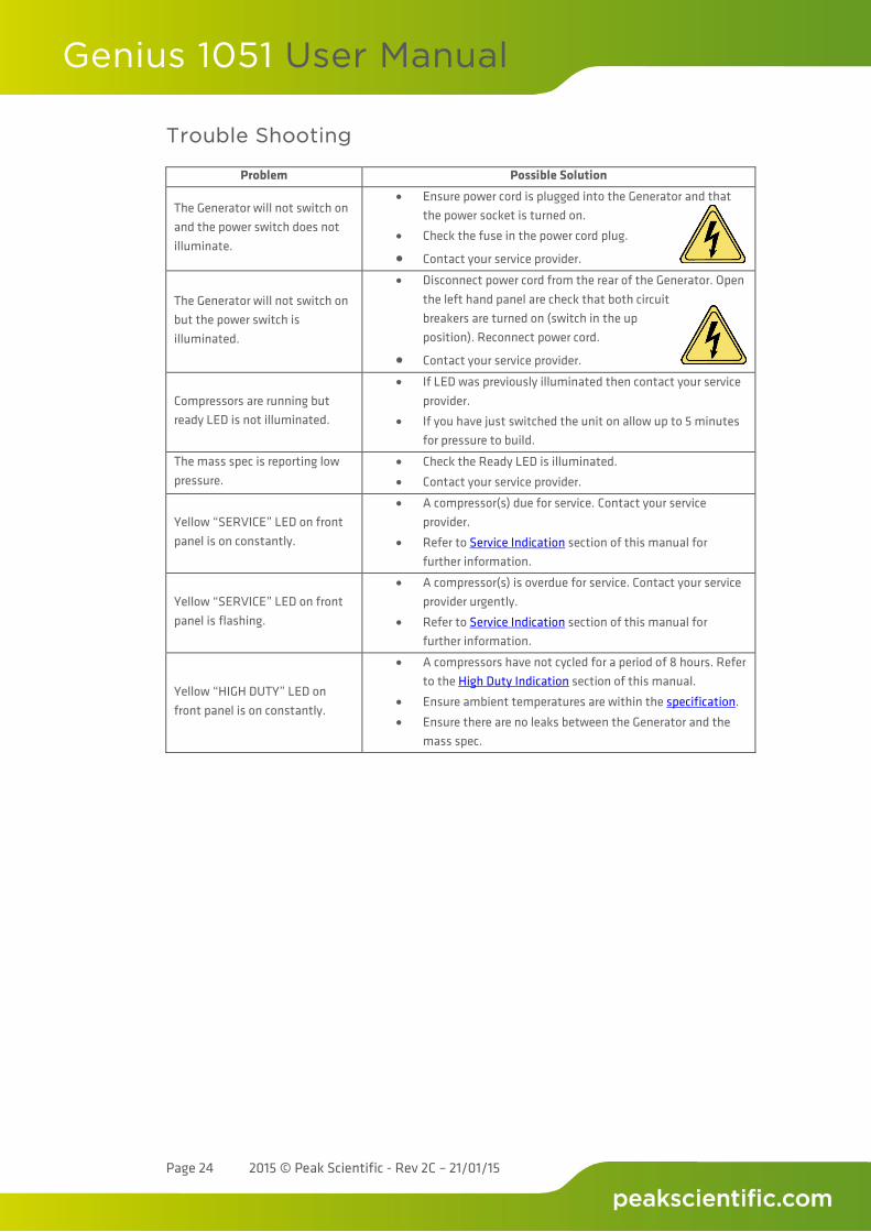
Trouble Shooting
Problem Possible Solution
The Generator will not switch on and the power switch does not illuminate.
• Ensure power cord is plugged into the Generator and that the power socket is turned on.
• Check the fuse in the power cord plug.
• Contact your service provider.
The Generator will not switch on but the power switch is illuminated.
• Disconnect power cord from the rear of the Generator. Open the left hand panel are check that both circuit breakers are turned on (switch in the up position). Reconnect power cord.
• Contact your service provider.
Compressors are running but ready LED is not illuminated.
• If LED was previously illuminated then contact your service provider.
• If you have just switched the unit on allow up to 5 minutes for pressure to build.
The mass spec is reporting low pressure.
• Check the Ready LED is illuminated. • Contact your service provider.
Yellow “SERVICE” LED on front panel is on constantly.
• A compressor(s) due for service. Contact your service provider.
• Refer to Service Indication section of this manual for further information.
Yellow “SERVICE” LED on front panel is flashing.
• A compressor(s) is overdue for service. Contact your service provider urgently.
• Refer to Service Indication section of this manual for further information.
Yellow “HIGH DUTY” LED on front panel is on constantly.
• A compressors have not cycled for a period of 8 hours. Refer to the High Duty Indication section of this manual.
• Ensure ambient temperatures are within the specification. • Ensure there are no leaks between the Generator and the
mass spec.
2015 © Peak Scientific - Rev 2C – 21/01/15
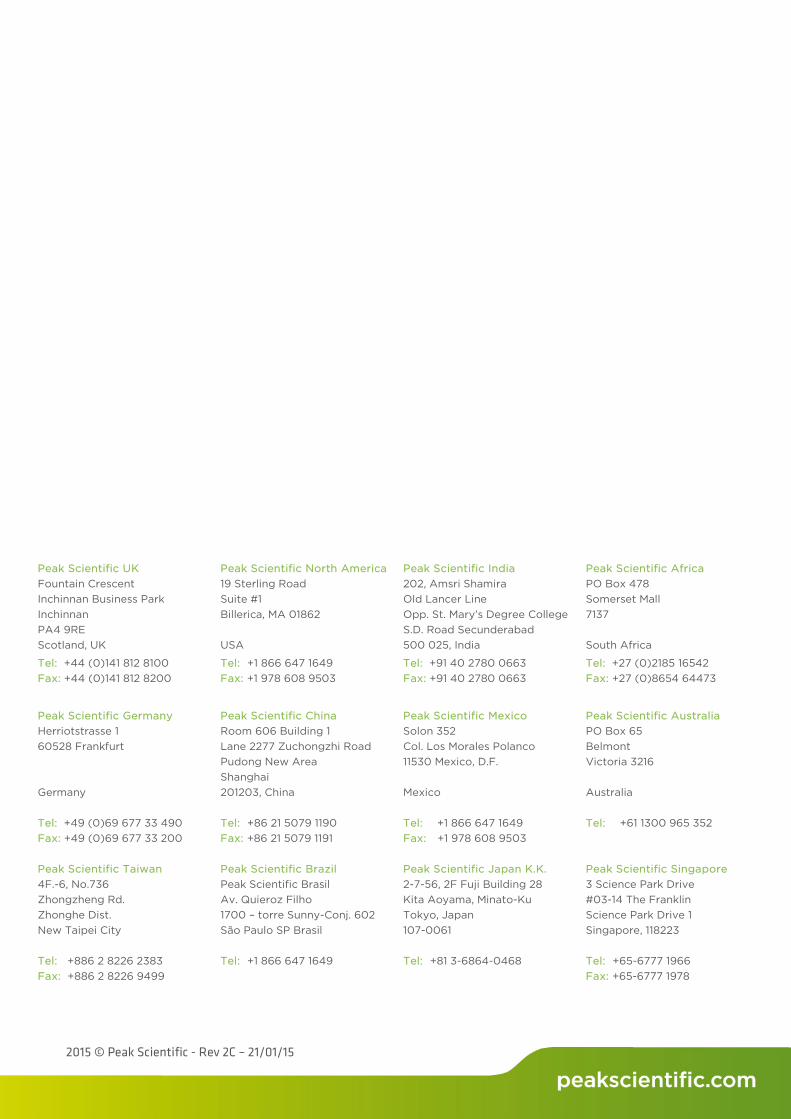
Peak Scientific UK Fountain Crescent Inchinnan Business Park Inchinnan PA4 9RE Scotland, UK
Peak Scientific North America 19 Sterling Road Suite #1 Billerica, MA 01862 USA
Peak Scientific India 202, Amsri Shamira Old Lancer Line Opp. St. Mary’s Degree College S.D. Road Secunderabad 500 025, India
Peak Scientific Africa PO Box 478 Somerset Mall 7137 South Africa
Tel: +44 (0)141 812 8100 Fax: +44 (0)141 812 8200
Tel: +1 866 647 1649 Fax: +1 978 608 9503
Tel: +91 40 2780 0663 Fax: +91 40 2780 0663
Tel: +27 (0)2185 16542 Fax: +27 (0)8654 64473
Peak Scientific Germany Herriotstrasse 1 60528 Frankfurt Germany
Peak Scientific China Room 606 Building 1 Lane 2277 Zuchongzhi Road Pudong New Area Shanghai 201203, China
Peak Scientific Mexico Solon 352 Col. Los Morales Polanco 11530 Mexico, D.F. Mexico
Peak Scientific Australia PO Box 65 Belmont Victoria 3216 Australia
Tel: +49 (0)69 677 33 490 Fax: +49 (0)69 677 33 200
Tel: +86 21 5079 1190 Fax: +86 21 5079 1191
Tel: +1 866 647 1649 Fax: +1 978 608 9503
Tel: +61 1300 965 352
Peak Scientific Taiwan 4F.-6, No.736 Zhongzheng Rd. Zhonghe Dist. New Taipei City Tel: +886 2 8226 2383 Fax: +886 2 8226 9499
Peak Scientific Brazil Peak Scientific Brasil Av. Quieroz Filho 1700 – torre Sunny-Conj. 602 São Paulo SP Brasil Tel: +1 866 647 1649
Peak Scientific Japan K.K. 2-7-56, 2F Fuji Building 28 Kita Aoyama, Minato-Ku Tokyo, Japan 107-0061 Tel: +81 3-6864-0468
Peak Scientific Singapore 3 Science Park Drive #03-14 The Franklin Science Park Drive 1 Singapore, 118223 Tel: +65-6777 1966 Fax: +65-6777 1978