Embed Size (px)
Citation preview
S
B
GENIEEVO Range Protection and Control Module P5 Unit Protection Cable Feeder with Backup Overcurrent and Earth fault Functional Description Issue A5
Revisions Issue A0 22.02.00 Draft Issue A1 09.03.00 Changed outputs O2 to be tripped on fault & for O12 to be Close
inhibit. Issue A2 19.04.00 Summary page updated, trip circuit supervision added to Output
O13 – changed to common alarm. Issue A3 21.09.00 Changed outputs O12 to be tripped on fault & for O2 to be Close
inhibit. Label (1) – L5 to L9. Summary sheet.
Issue A5
01.04.03
Changed to evo specification. Inclusion of disconnector and Vacuum bottles.
P5 rev A5 Page 2 of 25 2004 Schneider Electric
Abbreviations and Glossary of Terms
P5 rev A5 Page 3 of 25 2004 Schneider Electric
Contents REVISIONS....................................................................................................................................................... 2 CONTENTS ...................................................................................................................................................... 3 GENERAL......................................................................................................................................................... 4 ANSI CODE NUMBERS..................................................................................................................................... 4 CONTROL LOGIC .............................................................................................................................................. 4 PROTECTION SETTINGS.................................................................................................................................... 4 APPLICATION ................................................................................................................................................... 6 INTEGRATION OF UNIT PROTECTION................................................................................................................... 8 OVERCURRENT (ANSI 50/51) .......................................................................................................................... 9 EARTH FAULT (ANSI 50N/51N) ..................................................................................................................... 10 NEGATIVE SEQUENCE / UNBALANCE (ANSI 46)............................................................................................... 11 INPUT/OUTPUT LIST ........................................................................................................................................ 14 MESSAGE LIST............................................................................................................................................... 14 ANNUNCIATION .............................................................................................................................................. 15 TELECONTROL SIGNALS LIST.......................................................................................................................... 16 TELECONTROL COMMANDS LIST ..................................................................................................................... 16 GLOSSARY OF SYMBOLS ................................................................................................................................ 17 LOGIC SCHEME NAVIGATION........................................................................................................................... 17 CIRCUIT BREAKER PROTECTION, MONITOR & CONTROL .................................................................................. 18 PROTECTION FUNCTIONS ............................................................................................................................... 19 CIRCUIT BREAKER TRIP & CLOSE ................................................................................................................... 20 LOGIC DISCRIMINATION .................................................................................................................................. 21 RESETTING OF PROTECTION AND MESSAGES .................................................................................................. 22
Principle.................................................................................................................................................22 TRIP CIRCUIT SUPERVISION............................................................................................................................ 23
Principle.................................................................................................................................................23 Operation...............................................................................................................................................23
INTERTRIP OUTPUT SIGNAL (O14) .................................................................................................................. 24 Principle.................................................................................................................................................24 Operation...............................................................................................................................................24
DISTURBANCE RECORDER.............................................................................................................................. 25 Principle.................................................................................................................................................25 Operation...............................................................................................................................................25
Abbreviations and Glossary of Terms
P5 rev A5 Page 4 of 25 2004 Schneider Electric
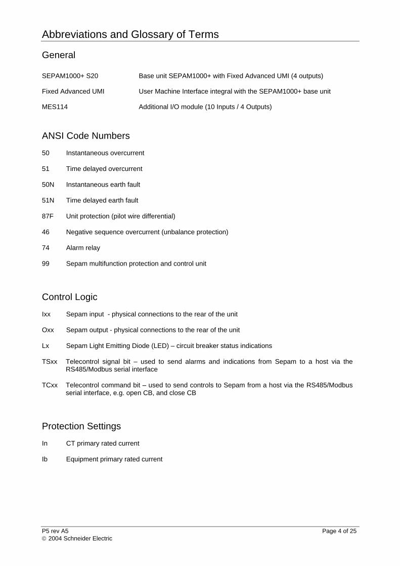
General SEPAM1000+ S20 Base unit SEPAM1000+ with Fixed Advanced UMI (4 outputs) Fixed Advanced UMI User Machine Interface integral with the SEPAM1000+ base unit MES114 Additional I/O module (10 Inputs / 4 Outputs)
ANSI Code Numbers
50 Instantaneous overcurrent
51 Time delayed overcurrent
50N Instantaneous earth fault
51N Time delayed earth fault
87F Unit protection (pilot wire differential)
46 Negative sequence overcurrent (unbalance protection)
74 Alarm relay
99 Sepam multifunction protection and control unit
Control Logic
Ixx Sepam input - physical connections to the rear of the unit
Oxx Sepam output - physical connections to the rear of the unit
Lx Sepam Light Emitting Diode (LED) – circuit breaker status indications
TSxx Telecontrol signal bit – used to send alarms and indications from Sepam to a host via the RS485/Modbus serial interface
TCxx Telecontrol command bit – used to send controls to Sepam from a host via the RS485/Modbus serial interface, e.g. open CB, and close CB
Protection Settings
In CT primary rated current
Ib Equipment primary rated current
P5 Summary Sheet
P5 rev A5 Page 5 of 25 2004 Schneider Electric
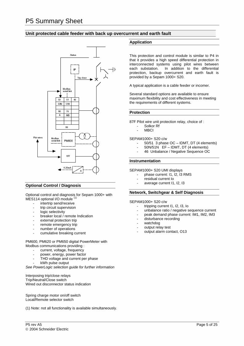
Unit protected cable feeder with back up overcurrent and earth fault
Optional Control / Diagnosis
Optional control and diagnosis for Sepam 1000+ with MES114 optional I/O module (1)
- intertrip send/receive - trip circuit supervision - logic selectivity - breaker local / remote Indication - external protection trip - remote emergency trip - number of operations - cumulative breaking current
PM600, PM620 or PM650 digital PowerMeter with Modbus communications providing :
- current, voltage, frequency - power, energy, power factor - THD voltage and current per phase - kWh pulse output
See PowerLogic selection guide for further information Interposing trip/close relays Trip/Neutral/Close switch Wired out disconnector status indication
Application This protection and control module is similar to P4 in that it provides a high speed differential protection in interconnected systems using pilot wires between each substation. In addition to the differential protection, backup overcurrent and earth fault is provided by a Sepam 1000+ S20. A typical application is a cable feeder or incomer. Several standard options are available to ensure maximum flexibility and cost effectiveness in meeting the requirements of different systems. Protection 87F Pilot wire unit protection relay, choice of :
- Solkor Rf - MBCI
SEPAM1000+ S20 c/w
- 50/51 3 phase OC – IDMT, DT (4 elements) - 50N/51N EF – IDMT, DT (4 elements) - 46 Unbalance / Negative Sequence OC
Instrumentation SEPAM1000+ S20 UMI displays
- phase current: I1, I2, I3 RMS - residual current Io - average current I1, I2, I3
Network, Switchgear & Self Diagnosis SEPAM1000+ S20 c/w
- tripping current I1, I2, I3, Io - unbalance ratio / negative sequence current - peak demand phase current: IM1, IM2, IM3 - disturbance recording - watchdog - output relay test - output alarm contact, O13
Spring charge motor on/off switch Local/Remote selector switch (1) Note: not all functionality is available simultaneously.
Application
P5 rev A5 Page 6 of 25 2004 Schneider Electric
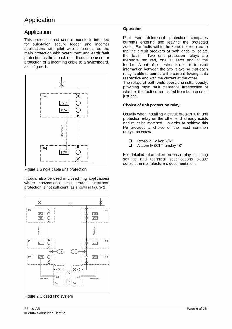
Application This protection and control module is intended for substation secure feeder and incomer applications with pilot wire differential as the main protection with overcurrent and earth fault protection as the a back-up. It could be used for protection of a incoming cable to a switchboard, as in figure 1.
Figure 1 Single cable unit protection It could also be used in closed ring applications where conventional time graded directional protection is not sufficient, as shown in figure 2.
Figure 2 Closed ring system
Operation Pilot wire differential protection compares currents entering and leaving the protected zone. For faults within the zone it is required to trip the circuit breakers at both ends to isolate the fault. Two unit protection relays are therefore required, one at each end of the feeder. A pair of pilot wires is used to transmit information between the two relays so that each relay is able to compare the current flowing at its respective end with the current at the other. The relays at both ends operate simultaneously, providing rapid fault clearance irrespective of whether the fault current is fed from both ends or just one. Choice of unit protection relay Usually when installing a circuit breaker with unit protection relay on the other end already exists and must be matched. In order to achieve this P5 provides a choice of the most common relays, as below. Reyrolle Solkor R/Rf Alstom MBCI Translay “S”
For detailed information on each relay including settings and technical specifications please consult the manufacturers documentation.
Pilo
t wire
s
50/51
87F
P5
87FP4
Pilo
t wire
s
50/51
87F
P5
87FP4
87FP4
Pilo
t wire
s
50/51
87F
P5
87FP4
87F P4
87F
P4
87F
P4
Pilot wires Pilot wires
Application
P5 rev A5 Page 7 of 25 2004 Schneider Electric
Sepam 1000+ backup overcurrent and earth fault The Genie SEPAM1000+ S20 includes the ‘Fixed Advanced User Machine Interface’ (UMI) which allows: display of measurements + switchgear
diagnosis data, display, clearing and resetting of alarm
messages display and input of protection settings
(multi-level password protected) access and input of relay parameter
settings (multi-level password protected) As a complement to the UMI integral with the unit, the ‘Expert UMI’ is available on a PC screen in the form of the SFT2841 software package and a connection to the RS232 link on the front panel of the SEPAM. The main functions performed by the SFT2841 software: changing of passwords, entry of general parameters (ratings,
integration period,….), entry of protection settings,
changing of program logic assignments,
enabling / disabling of functions,
saving of files & printing of reports
Note 1: Changing of passwords, output configuration and LED indicator assignment is only possible with the SFT2841 software. Note 2: The Sepam 1000+ used on Genie has a standard SFT2841 configuration file which can be supplied upon request.
Protection Functions
P5 rev A5 Page 8 of 25 2004 Schneider Electric
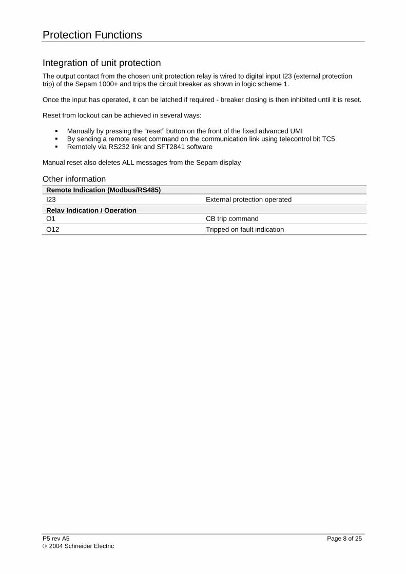
Integration of unit protection The output contact from the chosen unit protection relay is wired to digital input I23 (external protection trip) of the Sepam 1000+ and trips the circuit breaker as shown in logic scheme 1. Once the input has operated, it can be latched if required - breaker closing is then inhibited until it is reset. Reset from lockout can be achieved in several ways:
Manually by pressing the “reset” button on the front of the fixed advanced UMI By sending a remote reset command on the communication link using telecontrol bit TC5 Remotely via RS232 link and SFT2841 software
Manual reset also deletes ALL messages from the Sepam display Other information Remote Indication (Modbus/RS485)
I23 External protection operated
Relay Indication / Operation O1 CB trip command
O12 Tripped on fault indication

Protection Functions
P5 rev A5 Page 9 of 25 2004 Schneider Electric
Overcurrent (ANSI 50/51) SEPAM1000+ S20 provides four independent three-phase overcurrent elements (two of the elements can be used for logic discrimination) for protection against phase-phase faults, with a choice of definite or inverse time characteristics. Resetting of the overcurrent protection (on clearance of fault) can be either instantaneous or definite time with an adjustable delay.
Function Name 1 Description Message2
50/51-1 Group A Overcurrent – logic discrimination3 PHASE FAULT
50/51-1 Group B Overcurrent – time discrimination PHASE FAULT
50/51-2 Group A Overcurrent – logic discrimination3 PHASE FAULT
50/51-2 Group B Overcurrent – time discrimination PHASE FAULT 1. the names of the protection functions correspond to the text used on the fixed advanced UMI and in the SFT2841 software 2. the wording of the messages can be changed (please consult Schneider Electric)
3. depending on parameter setting The protection will trip the CB if the settings are exceeded. Once the protection has timed out, it can be latched if required - breaker closing is then inhibited until it is reset. Reset from lockout can be achieved in several ways:
Manually by pressing the “reset” button on the front of the fixed advanced UMI By sending a remote reset command on the communication link using telecontrol bit TC5 Remotely via RS232 link and SFT2841 software
Manual reset also deletes ALL messages from the Sepam display Setting ranges for Overcurrent elements Characteristic Pick-up current setting range 5 Time delay setting range 6
Definite time 0.3 to 24In Inst.; 50ms to 300s
IDMT 4 0.3 to 2.4In 100ms to 12.5s at 10Is
0.04 to 4.2 tms In : Primary rating of CT 4. IDMT curves according to BS142, IEC 255-4: standard inverse SI, very inverse VI, extremely inverse EI, ultra inverse UI, long time inverse LTI 5. 1A or 1 digit resolution, 5% accuracy 6. Time setting for IDMT can be either in ‘time at 10Is’ or tms format – depending on parameter setting.
Other information Timers
T1 Time delay reset 0; 0.05 to 300s (definite time)
Remote Indication (Modbus/RS485)
TS1 – 4 Overcurrent protection operated (4 elements)
Remote Control
TC1 Trip
TC2 Close
Disturbance Recorder
TS44 Disturbance recording record stored
Relay Indication / Operation O1 CB trip command
O12 Tripped on fault indication
Protection Functions
P5 rev A5 Page 10 of 25 2004 Schneider Electric
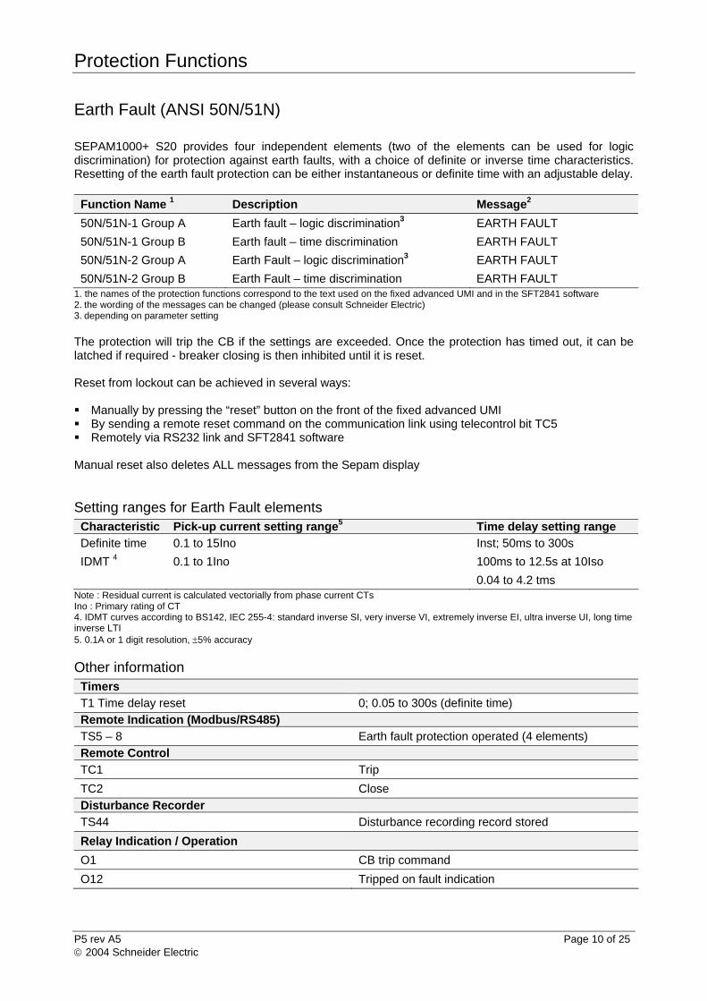
Earth Fault (ANSI 50N/51N) SEPAM1000+ S20 provides four independent elements (two of the elements can be used for logic discrimination) for protection against earth faults, with a choice of definite or inverse time characteristics. Resetting of the earth fault protection can be either instantaneous or definite time with an adjustable delay.
Function Name 1 Description Message2
50N/51N-1 Group A Earth fault – logic discrimination3 EARTH FAULT
50N/51N-1 Group B Earth fault – time discrimination EARTH FAULT
50N/51N-2 Group A Earth Fault – logic discrimination3 EARTH FAULT
50N/51N-2 Group B Earth Fault – time discrimination EARTH FAULT 1. the names of the protection functions correspond to the text used on the fixed advanced UMI and in the SFT2841 software 2.
the wording of the messages can be changed (please consult Schneider Electric)
3. depending on parameter setting
The protection will trip the CB if the settings are exceeded. Once the protection has timed out, it can be latched if required - breaker closing is then inhibited until it is reset. Reset from lockout can be achieved in several ways: Manually by pressing the “reset” button on the front of the fixed advanced UMI By sending a remote reset command on the communication link using telecontrol bit TC5 Remotely via RS232 link and SFT2841 software Manual reset also deletes ALL messages from the Sepam display Setting ranges for Earth Fault elements Characteristic Pick-up current setting range5 Time delay setting range
Definite time 0.1 to 15Ino Inst; 50ms to 300s
IDMT 4 0.1 to 1Ino 100ms to 12.5s at 10Iso
0.04 to 4.2 tms Note : Residual current is calculated vectorially from phase current CTs Ino : Primary rating of CT 4. IDMT curves according to BS142, IEC 255-4: standard inverse SI, very inverse VI, extremely inverse EI, ultra inverse UI, long time inverse LTI 5. 0.1A or 1 digit resolution, 5% accuracy Other information Timers
T1 Time delay reset 0; 0.05 to 300s (definite time)
Remote Indication (Modbus/RS485)
TS5 – 8 Earth fault protection operated (4 elements)
Remote Control
TC1 Trip
TC2 Close
Disturbance Recorder
TS44 Disturbance recording record stored
Relay Indication / Operation
O1 CB trip command
O12 Tripped on fault indication
Protection Functions
P5 rev A5 Page 11 of 25 2004 Schneider Electric
Negative Sequence / Unbalance (ANSI 46) SEPAM1000+ S20 provides protection against phase unbalance. Phase unbalance results in a negative sequence component in the phase current which can cause unwanted heating in electrical plant. It can be caused by an unbalanced supply, incorrect phase rotation, the loss of a phase, or two phase faults on long feeders. For the latter, it can offer protection against low levels of fault current which will not operate conventional overcurrent protection at sufficient speed to safeguard the system.
Function Name 1 Description Message 2
46 Negative Sequence / Unbalance UNBALANCE
1 the names of the protection function correspond to the text used on the fixed advanced UMI and in the SFT2841 software 2
the wording of the messages can be changed (please consult Schneider Electric).
The protection will pick-up when the negative sequence component of the phase currents is greater than the set point. Once the protection has timed out, it can be latched if required - breaker closing is then inhibited until it is reset. Reset from lockout can be achieved in several ways:
Manually By pressing the “reset” button on the front of the fixed advanced UMI By sending a remote reset command on the communication link using TC5 Remotely via RS232 link and SFT2841 software
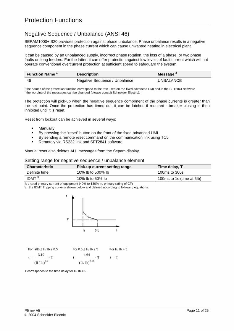
Manual reset also deletes ALL messages from the Sepam display Setting range for negative sequence / unbalance element Characteristic Pick-up current setting range Time delay, T
Definite time 10% Ib to 500% Ib 100ms to 300s
IDMT 3 10% Ib to 50% Ib 100ms to 1s (time at 5Ib) Ib : rated primary current of equipment (40% to 130% In, primary rating of CT) 3. the IDMT Tripping curve is shown below and defined according to following equations:
For Is/Ib Ii / Ib 0.5 For 0.5 Ii / Ib 5 For Ii / Ib > 5
T
)Ib/Ii(
19.3t
5.1 T
)Ib/Ii(
64.4t
96.0 Tt
T corresponds to the time delay for Ii / Ib = 5
Is 5Ib Ii
T
t
Protection Functions
P5 rev A5 Page 12 of 25 2004 Schneider Electric
Other information Remote Indication (Modbus/RS485)
TS12 Negative sequence protection operated Remote Control TC1 Trip
TC2 Close
Disturbance Recorder
TS44 Disturbance recording record stored
Relay Indication / Operation O1 CB trip command
O12 Tripped on fault indication
Instrumentation
P5 rev A5 Page 13 of 25 2004 Schneider Electric
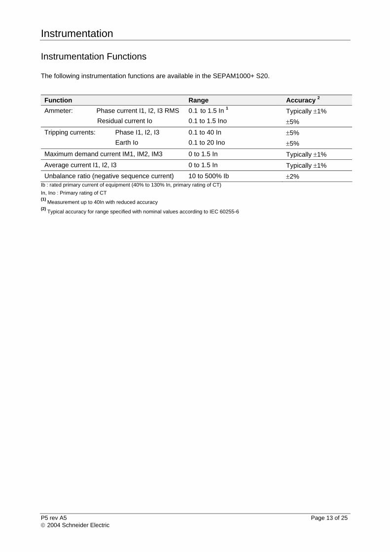
Instrumentation Functions The following instrumentation functions are available in the SEPAM1000+ S20.
Function Range Accuracy 2
Ammeter: Phase current I1, I2, I3 RMS
Residual current Io
0.1 to 1.5 In 1
0.1 to 1.5 Ino
Typically 1%
5%
Tripping currents: Phase I1, I2, I3
Earth Io
0.1 to 40 In
0.1 to 20 Ino
5%
5%
Maximum demand current IM1, IM2, IM3 0 to 1.5 In Typically 1%
Average current I1, I2, I3 0 to 1.5 In Typically 1%
Unbalance ratio (negative sequence current) 10 to 500% Ib 2% Ib : rated primary current of equipment (40% to 130% In, primary rating of CT)
In, Ino : Primary rating of CT (1)
Measurement up to 40In with reduced accuracy (2)
Typical accuracy for range specified with nominal values according to IEC 60255-6
Resource Allocation Tables
P5 rev A5 Page 14 of 25 2004 Schneider Electric
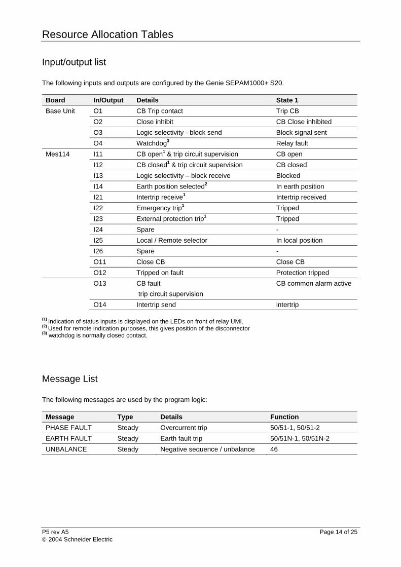
Input/output list The following inputs and outputs are configured by the Genie SEPAM1000+ S20.
Board In/Output Details State 1
Base Unit O1 CB Trip contact Trip CB
O2 Close inhibit CB Close inhibited
O3 Logic selectivity - block send Block signal sent
O4 Watchdog3 Relay fault
Mes114 I11 CB open1 & trip circuit supervision CB open
I12 CB closed1 & trip circuit supervision CB closed
I13 Logic selectivity – block receive Blocked
I14 Earth position selected2 In earth position
I21 Intertrip receive1 Intertrip received
I22 Emergency trip1 Tripped
I23 External protection trip1 Tripped
I24 Spare -
I25 Local / Remote selector In local position
I26 Spare -
O11 Close CB Close CB
O12 Tripped on fault Protection tripped
O13 CB fault
trip circuit supervision
CB common alarm active
O14 Intertrip send intertrip
(1) Indication of status inputs is displayed on the LEDs on front of relay UMI. (2) Used for remote indication purposes, this gives position of the disconnector (3) watchdog is normally closed contact.
Message List The following messages are used by the program logic:
Message Type Details Function
PHASE FAULT Steady Overcurrent trip 50/51-1, 50/51-2
EARTH FAULT Steady Earth fault trip 50/51N-1, 50/51N-2
UNBALANCE Steady Negative sequence / unbalance 46
Resource Allocation Tables
P5 rev A5 Page 15 of 25 2004 Schneider Electric
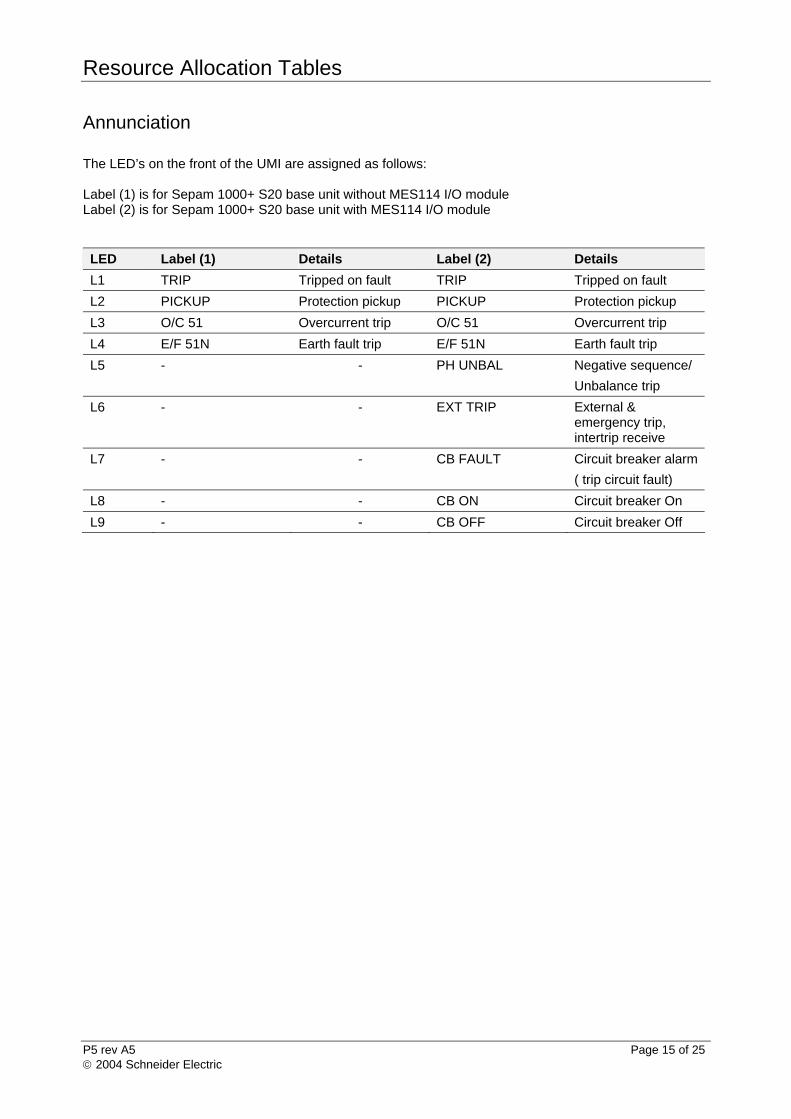
Annunciation The LED’s on the front of the UMI are assigned as follows: Label (1) is for Sepam 1000+ S20 base unit without MES114 I/O module Label (2) is for Sepam 1000+ S20 base unit with MES114 I/O module
LED Label (1) Details Label (2) Details
L1 TRIP Tripped on fault TRIP Tripped on fault
L2 PICKUP Protection pickup PICKUP Protection pickup
L3 O/C 51 Overcurrent trip O/C 51 Overcurrent trip
L4 E/F 51N Earth fault trip E/F 51N Earth fault trip
L5 - - PH UNBAL Negative sequence/
Unbalance trip
L6 - - EXT TRIP External & emergency trip, intertrip receive
L7 - - CB FAULT Circuit breaker alarm
( trip circuit fault)
L8 - - CB ON Circuit breaker On
L9 - - CB OFF Circuit breaker Off
Resource Allocation Tables
P5 rev A5 Page 16 of 25 2004 Schneider Electric
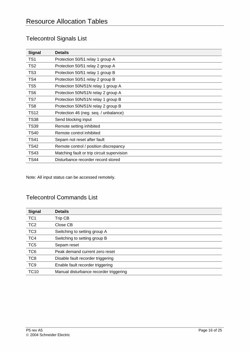
Telecontrol Signals List
Signal Details
TS1 Protection 50/51 relay 1 group A
TS2 Protection 50/51 relay 2 group A
TS3 Protection 50/51 relay 1 group B
TS4 Protection 50/51 relay 2 group B
TS5 Protection 50N/51N relay 1 group A
TS6 Protection 50N/51N relay 2 group A
TS7 Protection 50N/51N relay 1 group B
TS8 Protection 50N/51N relay 2 group B
TS12 Protection 46 (neg. seq. / unbalance)
TS38 Send blocking input
TS39 Remote setting inhibited
TS40 Remote control inhibited
TS41 Sepam not reset after fault
TS42 Remote control / position discrepancy
TS43 Matching fault or trip circuit supervision
TS44 Disturbance recorder record stored
Note: All input status can be accessed remotely.
Telecontrol Commands List
Signal Details
TC1 Trip CB
TC2 Close CB
TC3 Switching to setting group A
TC4 Switching to setting group B
TC5 Sepam reset
TC6 Peak demand current zero reset
TC8 Disable fault recorder triggering
TC9 Enable fault recorder triggering
TC10 Manual disturbance recorder triggering
Control Logic
P5 rev A5 Page 17 of 25 2004 Schneider Electric
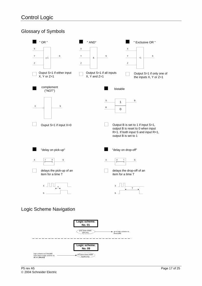
Glossary of Symbols
Logic Scheme Navigation
> 1
" OR "
X
Y
Z
S
Ouput S=1 if either inputX, Y or Z=1
Output S=1 if all inputsX, Y and Z=1
&
" AND"
X
Y
Z
S
Output S=1 if only one ofthe inputs X, Y or Z=1
=1
" Exclusive OR "
X
Y
Z
S
complement("NOT")
X S
Ouput S=1 if input X=0
"delay on pick-up"
SX t o
delays the pick-up of anitem for a time T
"delay on drop-off"
SX o t
delays the drop-off of anitem for a time T
Output B is set to 1 if input S=1,output B is reset to 0 when inputR=1. If both input S and input R=1,output B is set to 1
bistable
BS
R
1
0
TX
S
TX
S
prot close inhibit(09:LK3)
go to logic scheme no.9 and LK3
Logic scheme.No. 01
LK3:prot close inhibit01(09:LK3)
logic scheme no.9 link LK3trace back to logic scheme no.01 ref: (09:LK3)
Logic scheme.No. 09
Control Logic
P5 rev A5 Page 18 of 25 2004 Schneider Electric
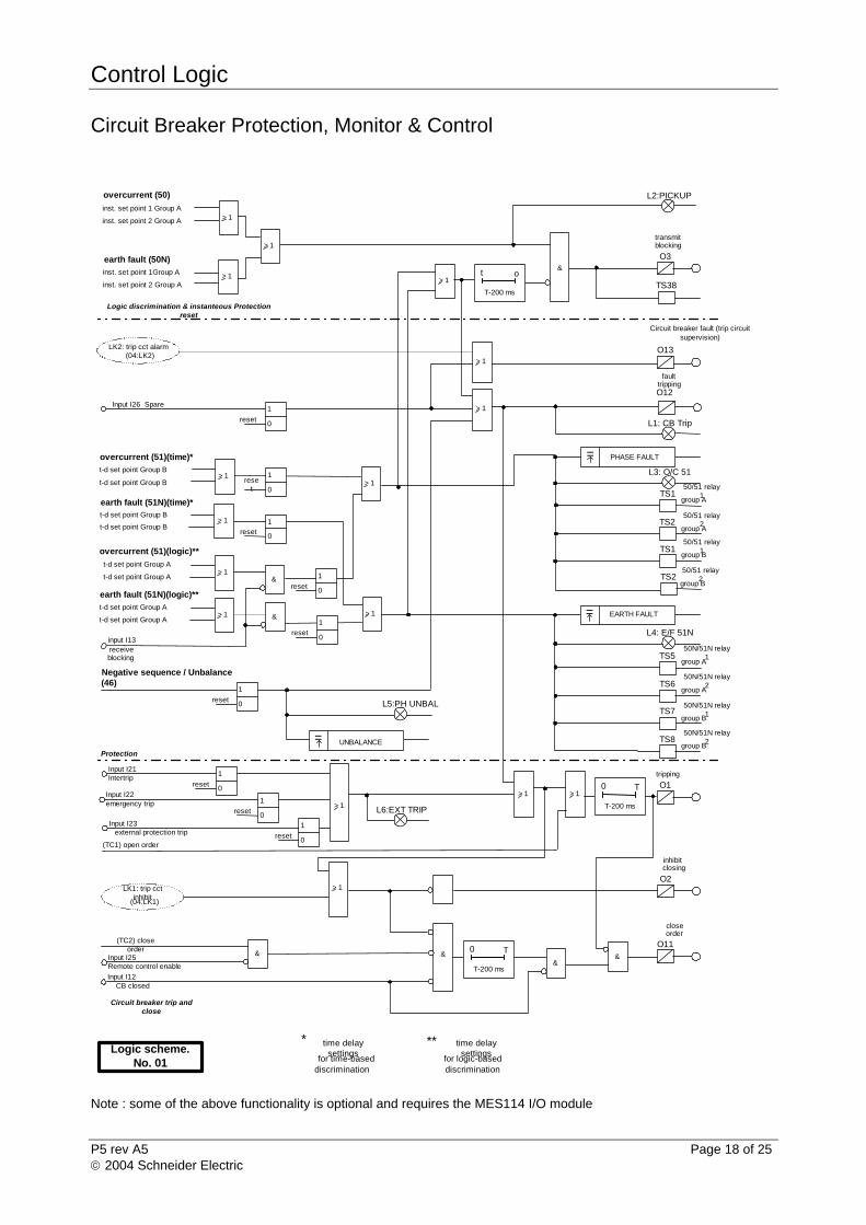
Circuit Breaker Protection, Monitor & Control
Note : some of the above functionality is optional and requires the MES114 I/O module
L6:EXT TRIP
time delaysettings
for time-baseddiscrimination
* time delaysettings
for logic-baseddiscrimination
**Logic scheme.
No. 01
input I13receiveblocking
overcurrent (51)(time)*
t-d set point Group B
t-d set point Group B
overcurrent (51)(logic)**
t-d set point Group A
t-d set point Group A
> 1
> 1
earth fault (51N)(time)*t-d set point Group B
t-d set point Group B
> 1
> 1
earth fault (51N)(logic)**
t-d set point Group A
t-d set point Group A> 1
&
& > 1
50/51 relay1
group A
50/51 relay2
group A
50/51 relay1
group B
50N/51N relay1
group A
50N/51N relay2
group A
50N/51N relay1
group B
TS850N/51N relay
2group B
TS5
TS6
TS7
Negative sequence / Unbalance(46)
O12
faulttripping
Input I21Intertrip
Input I22emergency trip
Input I23external protection trip
(TC1) open order
O2
inhibitclosing
> 1 > 1O1
tripping
T-200 ms
0 T
> 1
T-200 ms
0 T
&&
Input I25Remote control enable
(TC2) closeorder
Input I12CB closed
&
O11
closeorder
L1: CB Trip
TS250/51 relay
2group B
= PHASE FAULT
L4: E/F 51N
TS1
TS2
TS1
L3: O/C 51
L5:PH UNBAL
Input I26 Spare
&
> 1
overcurrent (50)
inst. set point 1 Group A
inst. set point 2 Group A
earth fault (50N)
inst. set point 1Group A
inst. set point 2 Group A
> 1
> 1
> 1
TS38
O3
transmitblocking
T-200 ms
t o
L2:PICKUP
O13
Circuit breaker fault (trip circuitsupervision)
= EARTH FAULT
= UNBALANCE
Logic discrimination & instanteous Protectionreset
Protection
Circuit breaker trip andclose
&
1
0rese
t
1
0reset
1
0reset
1
0reset
1
0reset
> 11
0reset
1
0reset
1
0reset
1
0reset
> 1
> 1
LK1: trip cctinhibit
(04:LK1)
LK2: trip cct alarm(04:LK2)
Control Logic
P5 rev A5 Page 19 of 25 2004 Schneider Electric
Protection Functions
Principle
The time delayed Overcurrent (51) and Earth fault (51N) protection function groups A and B are split in two, time delay settings for: Time-based discrimination – group B Logic-based discrimination – group A
Circuit breaker protection function Negative sequence / unbalance (46) will initiate circuit breaker tripping order. Output O2 is circuit breaker “Tripped on fault indication” activated when the circuit breaker has tripped on protection function fault, Output O13. Remote indication is provided for Overcurrent (51) and Earth fault (51N) protection operation. Common circuit breaker alarm is available on output O13 when trip circuit supervision activated.
Operation
The circuit breaker will initiate a trip as follows : Protection :
Time-based protection (51, 51N, 46) Logic-based discrimination (see Logic Discrimination)
The LED’s associated with protection trip are :
LED1 – Circuit breaker tripped on fault (protection trip) LED3 – Overcurrent (51) time or logic delayed protection trip operated LED4 – Earth fault (51N) time or logic delayed protection trip operated LED5 – Negative sequence / Unbalance (46) time-delayed protection trip operated LED6 – External protection trip inputs activated (input I21 intertrip receive, input I22
emergency trip or input I23 external protection trip) Remote indications :
TS1 – TS4 Overcurrent (51) relays 1 & 2 group A & B TS5 – TS8 Earth fault (51N) relays 1 & 2 group A & B
Control Logic
P5 rev A5 Page 20 of 25 2004 Schneider Electric
Circuit Breaker Trip & Close
Principle
The circuit breaker can only be tripped if the breaker is closed and in service position. Circuit breaker tripping order is issued via output O1 following initiation of a trip. Timer T provides a tripping order pulse for duration of 200ms. The circuit breaker closing order is issued via output O11. The closing order can only be issued providing no tripping order is currently issued, there is no circuit breaker fault and the circuit breaker is in the open position. Closing order is also issued via remote control close order (TC2). Timer T provides a closing order pulse for duration of 200ms. The reclosing of the circuit breaker is inhibited when output O12 is de-activated following the operation of circuit breaker protection. The reclosing of the circuit breaker is re-enabled once output O12 is activated.
Operation
The circuit breaker is controlled as follows : Tripped by :
protection (50/51, 50/51N, 46) remote control (TC1) external protection device1 Intertrip1 emergency trip push button1
Closed by :
local close switch remote control (TC2)
Close Inhibited by: protection trip circuit breaker open /close status mismatch (trip circuit supervision)
LED’s activated :
LED6 - External protection trip (input I21 intertrip receive, input I22 emergency trip & input I23 external protection trip).
Control Logic
P5 rev A5 Page 21 of 25 2004 Schneider Electric
Logic Discrimination
Principle
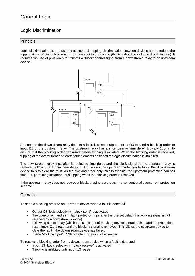
Logic discrimination can be used to achieve full tripping discrimination between devices and to reduce the tripping times of circuit breakers located nearest to the source (this is a drawback of time discrimination). It requires the use of pilot wires to transmit a “block” control signal from a downstream relay to an upstream device.
As soon as the downstream relay detects a fault, it closes output contact O3 to send a blocking order to input I13 of the upstream relay. The upstream relay has a short definite time delay, typically 100ms, to ensure that the blocking order can arrive before tripping is initiated. When the blocking order is received, tripping of the overcurrent and earth fault elements assigned for logic discrimination is inhibited. The downstream relay trips after its selected time delay and the block signal to the upstream relay is removed following a further time delay T. This allows the upstream protection to trip if the downstream device fails to clear the fault. As the blocking order only inhibits tripping, the upstream protection can still time out, permitting instantaneous tripping when the blocking order is removed. If the upstream relay does not receive a block, tripping occurs as in a conventional overcurrent protection scheme.
Operation To send a blocking order to an upstream device when a fault is detected
Output O3 ‘logic selectivity – block send’ is activated The overcurrent and earth fault protection trips after the pre-set delay (if a blocking signal is not
received by a downstream device) Following a time delay (which takes account of breaking device operation time and the protection
reset time), O3 is reset and the blocking signal is removed. This allows the upstream device to clear the fault if the downstream device has failed.
“Send blocking input” TS38 remote indication is transmitted To receive a blocking order from a downstream device when a fault is detected
Input I13 “Logic selectivity – block receive” is activated Tripping is inhibited until input I13 resets
I13
O3
I13
O3
Sepam
Sepam
_
+
I13
O3
Sepam
Control Logic
P5 rev A5 Page 22 of 25 2004 Schneider Electric
Resetting of Protection and Messages
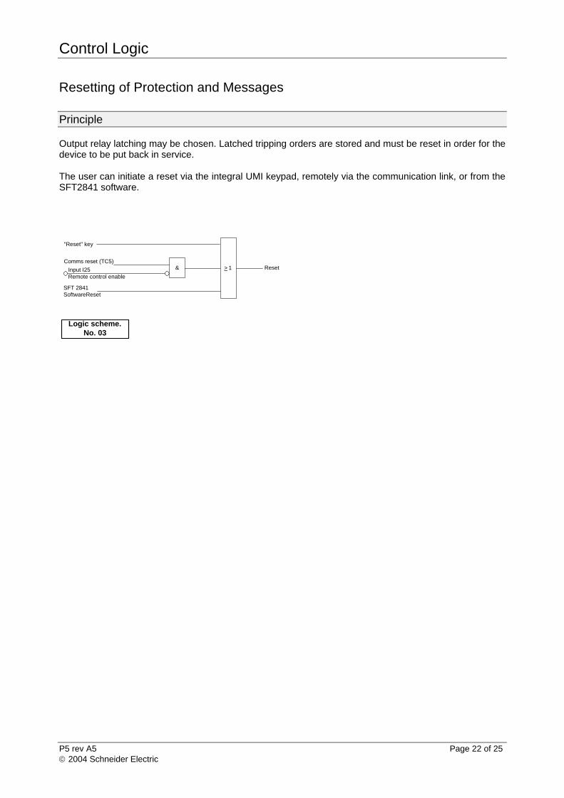
Principle Output relay latching may be chosen. Latched tripping orders are stored and must be reset in order for the device to be put back in service. The user can initiate a reset via the integral UMI keypad, remotely via the communication link, or from the SFT2841 software.
Reset> 1
"Reset" key
&Comms reset (TC5)
Input I25Remote control enable
SFT 2841SoftwareReset
Logic scheme.No. 03
Control Logic
P5 rev A5 Page 23 of 25 2004 Schneider Electric
Trip Circuit Supervision
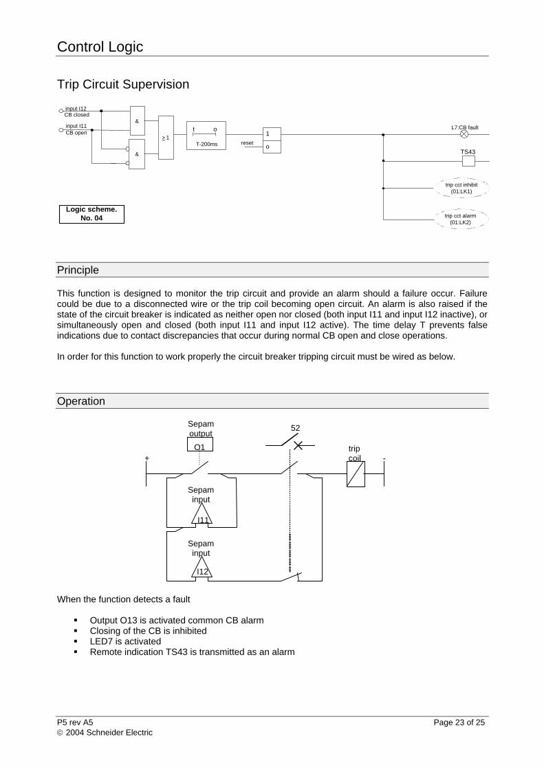
Principle This function is designed to monitor the trip circuit and provide an alarm should a failure occur. Failure could be due to a disconnected wire or the trip coil becoming open circuit. An alarm is also raised if the state of the circuit breaker is indicated as neither open nor closed (both input I11 and input I12 inactive), or simultaneously open and closed (both input I11 and input I12 active). The time delay T prevents false indications due to contact discrepancies that occur during normal CB open and close operations. In order for this function to work properly the circuit breaker tripping circuit must be wired as below.
Operation
When the function detects a fault
Output O13 is activated common CB alarm Closing of the CB is inhibited LED7 is activated Remote indication TS43 is transmitted as an alarm
O1
Sepamoutput
I11
I12
Sepaminput
Sepaminput
tripcoil
52
+ -
&
&
T-200ms
t oinput I11CB open
Logic scheme.No. 04
input I12CB closed
L7:CB fault
trip cct inhibit(01:LK1)
TS43
> 1reset
o
1
trip cct alarm(01:LK2)
Control Logic
P5 rev A5 Page 24 of 25 2004 Schneider Electric
Intertrip Output Signal (O14)
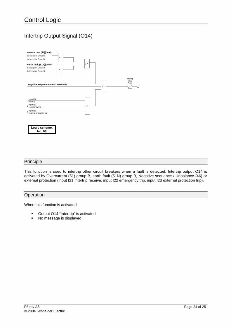
Principle This function is used to intertrip other circuit breakers when a fault is detected. Intertrip output O14 is activated by Overcurrent (51) group B, earth fault (51N) group B, Negative sequence / Unbalance (46) or external protection (input I21 intertrip receive, input I22 emergency trip, input I23 external protection trip).
Operation When this function is activated
Output O14 “Intertrip” is activated No message is displayed
overcurrent (51)(time)*
t-d set point Group B
t-d set point Group B
> 1
> 1
earth fault (51N)(time)*t-d set point Group B
t-d set point Group B
> 1
Input I21Intertrip
Input I22emergency trip
Input I23external protection trip
> 1
O14
intertripsend
> 1Negative sequence overcurrent(46)
Logic scheme.No. 08
Control Logic
P5 rev A5 Page 25 of 25
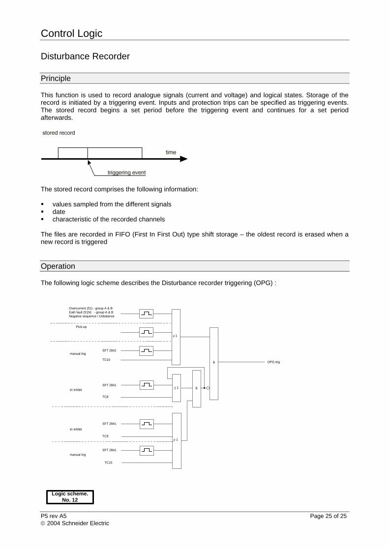
Disturbance Recorder
Principle This function is used to record analogue signals (current and voltage) and logical states. Storage of the record is initiated by a triggering event. Inputs and protection trips can be specified as triggering events. The stored record begins a set period before the triggering event and continues for a set period afterwards.
The stored record comprises the following information: values sampled from the different signals date characteristic of the recorded channels The files are recorded in FIFO (First In First Out) type shift storage – the oldest record is erased when a new record is triggered
Operation The following logic scheme describes the Disturbance recorder triggering (OPG) :
Overcurrent (51) - group A & BEath fault (51N) - group A & BNegative sequence / Unbalance
> 1
Logic scheme.No. 12
Pick-up
SFT 2841manual trig
> 1
&
&
TC10
TC8
> 1TC9
TC10
tri inhibit
tri inhibit
SFT 2841
SFT 2841
manual trig
SFT 2841
OPG trig
2004 Schneider Electric