Embed Size (px)
Citation preview
Genetic Algorithm based PID Tuning for Optimal Power Control of a Three-shaft Brayton Cycle based Power Conversion Unit
K.R. Uren* and G. van Schoor*
*School of Electrical, Electronic and Computer Engineering, North-West University, Potchefstroom Campus, P/Bag X6001, Potchefstroom, 2520, South Africa (Tel: +27 18 299 1236; e-mail: [email protected]).
Abstract: This paper considers the development of a PID control strategy to optimally control the power output of a High Temperature Gas-cooled Reactor (HTGR) power plant. A specific type of HTGR called the Pebble Bed Modular Reactor (PBMR) that utilises a closed recuperative Brayton cycle with helium as working fluid is considered. The power control of this kind of plant is significantly different from conventional steam cycle nuclear power plants. A distinguishing feature that complicates the control is the use of three separate shafts for different compressor/turbine or turbine/generator pairs. In addition the power output cannot be directly controlled by means of an upstream valve that regulates the flow through the power turbine, as is the case with conventional steam cycles. This paper addresses these challenges by means of a control strategy consisting of four PID control loops. The controller gains are optimised by means of a Genetic Algorithm (GA) that uses real-valued genes and the ITAE performance measure as a cost function. The control strategy is implemented and evaluated on a linear Simulink® model of the PBMR Power Conversion Unit (PCU). Results are presented illustrating the performance of the GA optimised PID control strategy. Keywords: Genetic algorithms, PID control, optimal control, nuclear power stations, Brayton cycle.
1. INTRODUCTION
A promising reactor technology today is the High Temperature Gas-cooled Reactor (HTGR) which meets the requirements of fourth generation nuclear reactors (IAEA, 1997). This type of reactor offers advantages such as inherent safety and improved economics (Koster et al., 2003). Research on HTGR technology is underway in many countries around the world including South Africa.
South Africa focuses on a specific type of HTGR called the Pebble Bed Modular Reactor (PBMR), which uses fuel material in the form of pebbles (Janse van Rensburg & Kleingeld, 2010). Hot gas from the reactor drives a closed loop three-shaft Brayton cycle. The plant is modular in the sense that a number of units can be combined to supply electricity to the electrical grid.
The electrical grid presents certain control challenges that may include rapid up or down ramping of the power according to demand. The plant may also be required to make abrupt steps in power delivery to counteract severe grid disturbances. Conventional nuclear reactors using steam cycles can be directly controlled by means of an upstream valve that regulates the flow through the power turbine. The PBMR plant design differs significantly from conventional steam cycle plants in terms of dynamics and control philosophy.
This paper presents a PID control strategy to control the power output of the plant under load-following conditions. The strategy will include four PID controllers controlling
different gas inventory mechanisms. This presents a challenge of optimising different interdependent PID loops. A solution to this problem is to use optimisation techniques that are able to adjust PID parameters automatically according to some performance criterion. A powerful technique often used for this purpose is a Genetic Algorithm (GA) (Alfaro-Cid & McGookin, 2006; O’mahony et al., 2000).
The developed control strategy will be evaluated on a linear Simulink® model of the PBMR PCU (Rubin & J. Pritchard, 2002) (Uren, 2009). First, in section 2, an overview of the operation and control of the PCU is given. This is followed by a discussion of the linear Simulink® model used for control. Then, in section 3, the proposed PID control strategy is discussed, followed by the GA optimisation in section 4. In section 5 the control strategy is demonstrated by evaluating the GA optimised control strategy in simulation. Finally, in section 6, conclusions and perspectives are given.
2. THREE-SHAFT BRAYTON CYCLE BASED POWER CONVERSION UNIT
2.1 Operation overview
The typical three-shaft Brayton cycle based power plant of the original PBMR design is a nuclear power plant that can produce approximately 110 MW of electrical power (G. Greyvenstein, 2003). It is a graphite-moderated, helium-cooled reactor that uses the Brayton direct gas cycle to
IFAC Conference on Advances in PID Control PID'12 Brescia (Italy), March 28-30, 2012 FrPS.4
convert the heat, which is generated in the core by nuclear fission. Heat is transferred to the coolant gas (in this case helium), and converted into electrical energy by means of a gas turbo-generator (Van Niekerk et al., 2004).
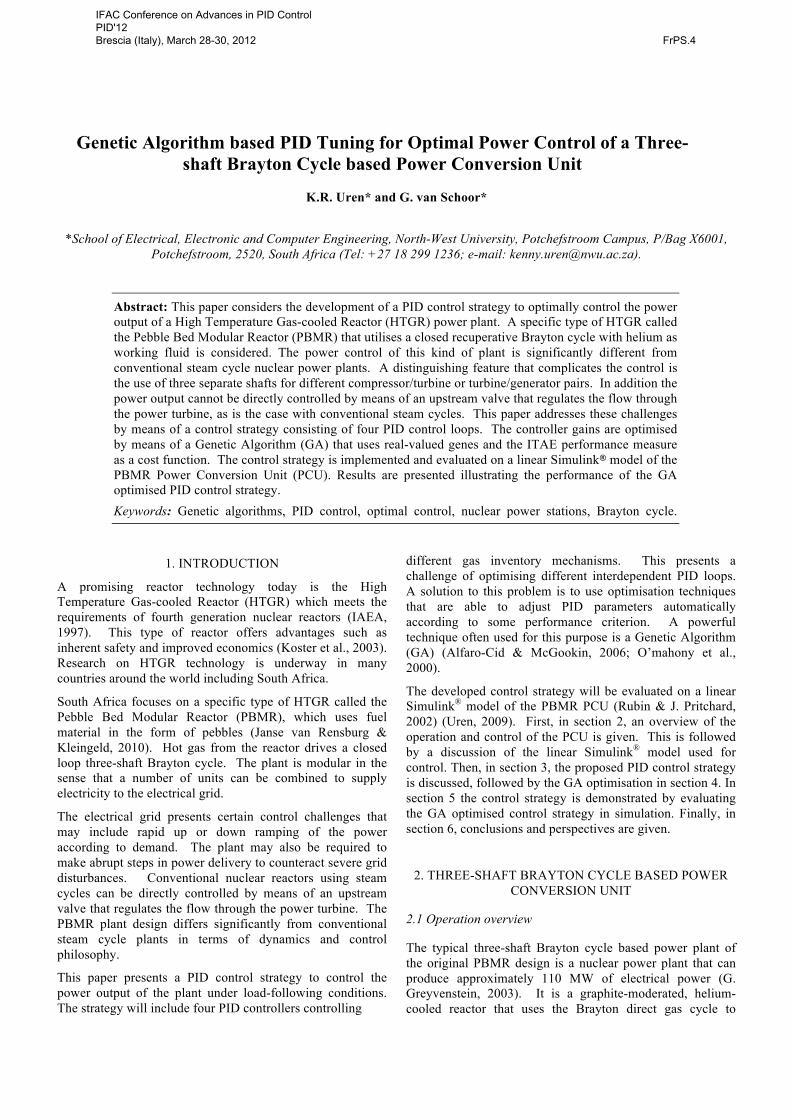
Fig.1 shows a schematic diagram of the plant layout. At full power, helium enters the reactor at a temperature of approximately 500 °C and at a pressure of 70 bar. The helium moves downward among hot fuel spheres. It then picks up heat from the fuel spheres, which have been heated by the nuclear reaction. The helium leaves the reactor at a very high temperature of approximately 900 °C.
Next, the helium gas moves through the High-pressure Turbine (HPT), which drives the High-pressure Compressor (HPC). Then the helium moves through the Low-pressure Turbine (LPT), which drives the Low-pressure Compressor (LPC).
Fig. 1. PBMR power plant layout.
From the LPT the helium moves through the Power Turbine (PT), which drives the generator. At this stage the helium is still at a very high temperature. It then passes through the recuperator where some heat is transferred to the low temperature helium returning to the reactor.
After the recuperator, helium is cooled down by means of a pre-cooler. This increases the density of the helium and improves the efficiency of the compressors. From the pre-cooler a first stage compression is achieved by the LPC. From the LPC the helium is cooled down further when it passes through the intercooler. From the intercooler a second stage of compression is achieved by the HPC after which the helium passes through the recuperator that heats the helium up again. The helium then returns to the reactor.
2.2 Power control overview
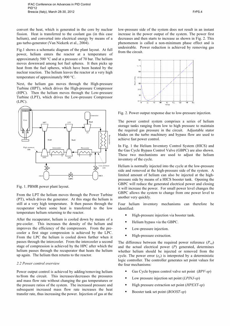
Power output control is achieved by adding/removing helium to/from the circuit. This increases/decreases the pressures and mass flow rate without changing the gas temperatures or the pressure ratios of the system. The increased pressure and subsequent increased mass flow rate increases the heat transfer rate, thus increasing the power. Injection of gas at the
low-pressure side of the system does not result in an instant increase in the power output of the system. The power first decreases and then starts to increase as shown in Fig. 2. This phenomenon is called a non-minimum phase effect and is undesirable. Power reduction is achieved by removing gas from the circuit.
!
Fig. 2. Power output response due to low-pressure injection.
The power control system comprises a series of helium storage tanks ranging from low to high pressure to maintain the required gas pressure in the circuit. Adjustable stator blades on the turbo machinery and bypass flow are used to achieve fast power control.
In Fig. 1 the Helium Inventory Control System (HICS) and the Gas Cycle Bypass Control Valve (GBPC) are also shown. These two mechanisms are used to adjust the helium inventory of the cycle.
Helium is normally injected into the cycle at the low-pressure side and removed at the high-pressure side of the system. A limited amount of helium can also be injected at the high- pressure side by means of a HICS booster tank. Opening the GBPC will reduce the generated electrical power and closing it will increase the power. For small power level changes the GBPC allows the system to change from one power level to another very quickly.
Four helium inventory mechanisms can therefore be identified:
§ High-pressure injection via booster tank.
§ Helium bypass via the GBPC.
§ Low-pressure injection.
§ High-pressure extraction.
The difference between the required power reference (Pref) and the actual electrical power (P) generated, determines whether helium should be injected or removed from the cycle. The power error (ep) is interpreted by a deterministic logic controller. The controller generates set point values for the four mechanisms:
§ Gas Cycle bypass control valve set point (BPV-sp)
§ Low pressure injection set point (LPINJ-sp)
§ High pressure extraction set point (HPEXT-sp)
§ Booster tank set point (BOOST-sp)
IFAC Conference on Advances in PID Control PID'12 Brescia (Italy), March 28-30, 2012 FrPS.4
These set point values need to be carefully adjusted, since the control loops are interdependent. An innovative control strategy is therefore needed to generate set point values that will result in smooth power responses and sufficient reserve capacity. A PID type control strategy will be considered to address these control requirements.
2.3 Linear model of the power conversion unit
Detailed thermo-hydraulic models and models describing the reactor neutronics of the PBMR PCU exists (van Ravenswaay et al., 2004)(du Toit et al., 2006). These models present valuable answers during the design process, but present no insight regarding the dominant dynamics of the system needed for control system design.
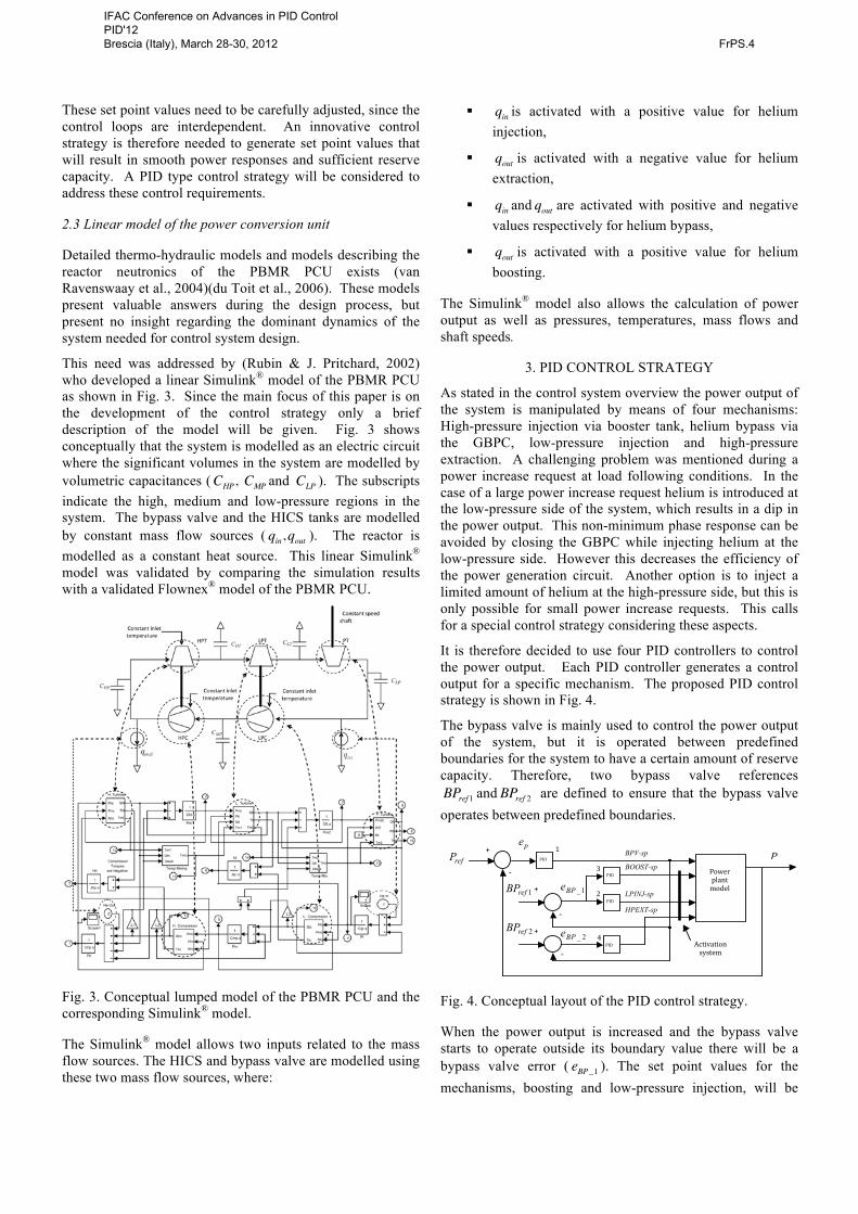
This need was addressed by (Rubin & J. Pritchard, 2002) who developed a linear Simulink® model of the PBMR PCU as shown in Fig. 3. Since the main focus of this paper is on the development of the control strategy only a brief description of the model will be given. Fig. 3 shows conceptually that the system is modelled as an electric circuit where the significant volumes in the system are modelled by volumetric capacitances (CHP, CMP and CLP ). The subscripts indicate the high, medium and low-pressure regions in the system. The bypass valve and the HICS tanks are modelled by constant mass flow sources ( qin,qout ). The reactor is modelled as a constant heat source. This linear Simulink® model was validated by comparing the simulation results with a validated Flownex® model of the PBMR PCU.
Fig. 3. Conceptual lumped model of the PBMR PCU and the corresponding Simulink® model.
The Simulink® model allows two inputs related to the mass flow sources. The HICS and bypass valve are modelled using these two mass flow sources, where:
§ qin is activated with a positive value for helium injection,
§ qout is activated with a negative value for helium extraction,
§ qin and qout are activated with positive and negative values respectively for helium bypass,
§ qout is activated with a positive value for helium boosting.
The Simulink® model also allows the calculation of power output as well as pressures, temperatures, mass flows and shaft speeds.
3. PID CONTROL STRATEGY
As stated in the control system overview the power output of the system is manipulated by means of four mechanisms: High-pressure injection via booster tank, helium bypass via the GBPC, low-pressure injection and high-pressure extraction. A challenging problem was mentioned during a power increase request at load following conditions. In the case of a large power increase request helium is introduced at the low-pressure side of the system, which results in a dip in the power output. This non-minimum phase response can be avoided by closing the GBPC while injecting helium at the low-pressure side. However this decreases the efficiency of the power generation circuit. Another option is to inject a limited amount of helium at the high-pressure side, but this is only possible for small power increase requests. This calls for a special control strategy considering these aspects.
It is therefore decided to use four PID controllers to control the power output. Each PID controller generates a control output for a specific mechanism. The proposed PID control strategy is shown in Fig. 4.
The bypass valve is mainly used to control the power output of the system, but it is operated between predefined boundaries for the system to have a certain amount of reserve capacity. Therefore, two bypass valve references BPref 1 and BPref 2 are defined to ensure that the bypass valve operates between predefined boundaries. !
Activation!system!
P !PID!
PID!
PID!
PID!
refP !pe !
1!
+!
+!
+!1!
1!
1_BPe !
2_BPe !
1refBP !
2refBP !
Power!plant!model!
BPV-sp
LPINJ-sp
HPEXT-sp
BOOST-sp
1!
2!
3!
4!
Fig. 4. Conceptual layout of the PID control strategy.
When the power output is increased and the bypass valve starts to operate outside its boundary value there will be a bypass valve error ( eBP_1 ). The set point values for the mechanisms, boosting and low-pressure injection, will be
IFAC Conference on Advances in PID Control PID'12 Brescia (Italy), March 28-30, 2012 FrPS.4
generated according to eBP_1 . This will restore the bypass valve to operate within its boundary values.
In the case where the power output is decreased and the bypass valve again starts to operate outside its boundary value there will be a bypass valve error ( eBP_2 ). The set point value for the mechanism, high-pressure extraction, will be generated according to eBP_2 . This will restore the bypass valve to operate within its boundary values.
The actual power output of the system is subtracted from the desired power reference to obtain the power error, ep . The negative of the power error is connected to the PID controller numbered 1. This PID controller generates the bypass valve set point (BPV-sp).
The BPV-sp is subtracted from the first bypass valve reference ( BPref 1 ) to obtain a bypass valve error ( eBP_1 ). This bypass valve error is the input to two other PID controllers numbered 2 and 3 that generate the set point values (LPINJ-sp, BOOST-sp) for low-pressure injection and boosting respectively. The activation system allows the LPINJ-sp and BOOST-sp to be ported to the system only when ep > 0 MW and ep > 5 MW respectively.
The BPV-sp is also subtracted from a second bypass valve reference ( BPref 2 ) to obtain a second bypass valve error ( eBP_2 ). This bypass valve error is passed to the PID controller numbered 4 that generates the set point value (HPEXT-sp) for high-pressure extraction. The HPEXT-sp is only ported to the system when ep < 0 MW .
Since it is desired to optimally control the power output a GA-based tuning algorithm for the PID parameters is considered next.
4. GA-BASED OPTIMISATION OF THE PID CONTROL PARAMETERS
Significant efforts in terms of research have been made on tuning methods of PID controllers. The Ziegler-Nichols tuning formula is perhaps the most well known tuning method for SISO systems. It is beyond the scope of this paper to cite all the investigations. This paper however, will focus on tuning PID controllers using a GA due to certain advantages.
GA-based tuning were compared with Ziegler-Nichols tuning in a number of studies and showed improved results (Kau et al., 2002)(Gündoğdu, 2005). From these studies it was concluded that GA solutions are less oscillatory than those of Ziegler-Nichols in both step response and controller output. Although a comparatively smaller rise time and settling time were obtained from Ziegler-Nichols, the GA solution had a very small overshoot with respect to final values.
Generally a GA is considered as a random search method that mimics natural biological evolution. The procedure starts by randomly generating an initial population consisting of individuals that are considered as possible solutions. The
population is then evaluated by means of an objective function. Next the best individuals are selected and used to generate offspring by means of crossover and mutation operations. These offspring are inserted into the population and then the whole population is evaluated again. This process iterates for a number of generations until an optimal population is found.
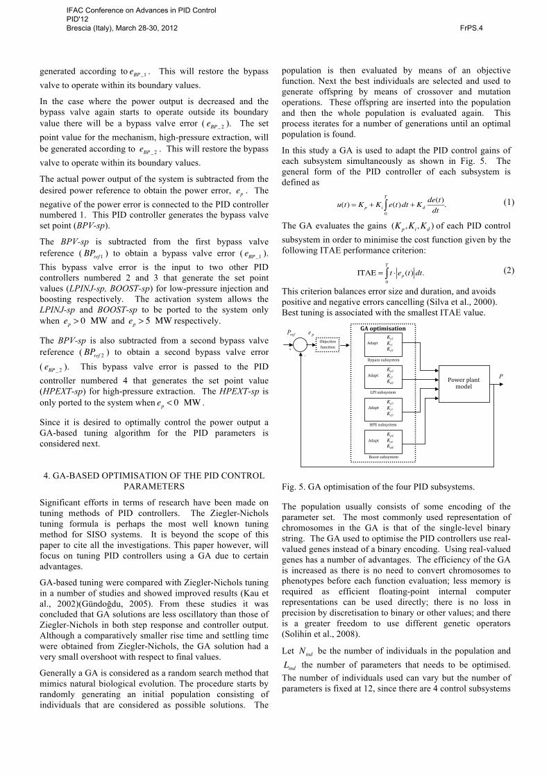
In this study a GA is used to adapt the PID control gains of each subsystem simultaneously as shown in Fig. 5. The general form of the PID controller of each subsystem is defined as
u(t) = Kp + Ki e(t)dt + Kdde(t)dt0
T
∫ . (1)
The GA evaluates the gains (Kp,Ki,Kd ) of each PID control subsystem in order to minimise the cost function given by the following ITAE performance criterion:
ITAE = t ⋅ ep(t) dt0
T
∫ . (2)
This criterion balances error size and duration, and avoids positive and negative errors cancelling (Silva et al., 2000). Best tuning is associated with the smallest ITAE value. !
refP !
+!#!
P !
pe !
Objective!function!
GA#optimisation#
!Bypass!subsystem!
LPI!subsystem!
HPE!subsystem!
!Boost!subsystem!
Kp1 Ki1 Kd1
!
Adapt!
Kp2 Ki2 Kd2
!!
Kp3 Ki3 Kd3 !
Kp4 Ki4 Kd4 !
Adapt!
Adapt!
Adapt!
Power!plant!model!
Fig. 5. GA optimisation of the four PID subsystems.
The population usually consists of some encoding of the parameter set. The most commonly used representation of chromosomes in the GA is that of the single-level binary string. The GA used to optimise the PID controllers use real-valued genes instead of a binary encoding. Using real-valued genes has a number of advantages. The efficiency of the GA is increased as there is no need to convert chromosomes to phenotypes before each function evaluation; less memory is required as efficient floating-point internal computer representations can be used directly; there is no loss in precision by discretisation to binary or other values; and there is a greater freedom to use different genetic operators (Solihin et al., 2008).
Let Nind be the number of individuals in the population and Lind the number of parameters that needs to be optimised. The number of individuals used can vary but the number of parameters is fixed at 12, since there are 4 control subsystems
IFAC Conference on Advances in PID Control PID'12 Brescia (Italy), March 28-30, 2012 FrPS.4

each containing 3 PID gains. The initial population is therefore an Nind × Lind matrix.
Before moving to the optimisation process of the PID control strategy, certain parameters of the GA have to be defined first. The population size, generations and boundary values for the GA used are summarised in Table 1.
Table 1. GA parameters
PID subsystem 1 Kp1 Ki1 Kd1
Lower Boundary 0 0 0 Upper Boundary 200 0.01 200
PID subsystem 2 Kp2 Ki2 Kd2 Lower Boundary 0 0 0 Upper Boundary 200 0.01 200
PID subsystem 3 Kp3 Ki3 Kd3 Lower Boundary 0 0 0 Upper Boundary 200 0.01 200
PID subsystem 4 Kp4 Ki4 Kd4 Lower Boundary 0 0 0 Upper Boundary 200 0.01 200
Population size and number of generations Nind 40
Lind 12 Number of generations 100
It was decided to choose the population size equal to 40 to ensure a large number of different individuals at the beginning of the GA optimisation process. A hundred generations was chosen to allow the GA enough time to generate optimal values according to the objective function. The meaningful ranges of the gain constants are determined through simulation.
5. RESULTS
The PID gain values were optimised by subjecting the system to a specific power reference sequence as given in Fig. 6. The sequence comprises three scenarios. The first scenario increases the power level from 100 MW to 106 MW. This large increase in the power results in the utilisation of the booster tank to inject a limited amount of helium at the high-pressure side of the system. At the same time it also utilises the bypass valve in conjunction with the booster tank. Power increase is achieved by closing the bypass valve. In the second scenario the power level is decreased from 106 MW to 103 MW. This is achieved by opening the bypass valve. The third scenario allows a power level increase from 103 MW to 105 MW. In order to increase the power, the mass flow through the bypass valve needs to decrease. This power sequence therefore allows all the power manipulation mechanisms to be utilised for a range of power levels.
Fig. 6. Power reference sequence
The optimal gain values for the PID control strategy after 100 generations are summarised in Table 2.
Table 2. Optimal gain values of the PID control strategy
PID controller Kp Ki Kd
1 (BPV-sp) 47.67 0 37.75
2 (LPINJ-sp) 25.35 0 38.23
3 (HPEXT-sp) 134.61 0 199.61
4 (BOOST-sp) 194.69 157.91 62.16
It is clear that the GA chose the integral gains close to zero. This shows that proportional derivative control is sufficient. The plot of the objective function values of the fittest individual in each generation is shown in Fig. 7. It can be seen that after approximately 20 generations the objective function value converges. The response of the optimal PID control strategy is shown in Fig. 8.
Fig. 7. Objective value of the fittest individual in each generation.
IFAC Conference on Advances in PID Control PID'12 Brescia (Italy), March 28-30, 2012 FrPS.4
0 20 40 60 80 100 120 140 160100
101
102
103
104
105
106
107
Time (s)
Powe
r (M
W)
PPref
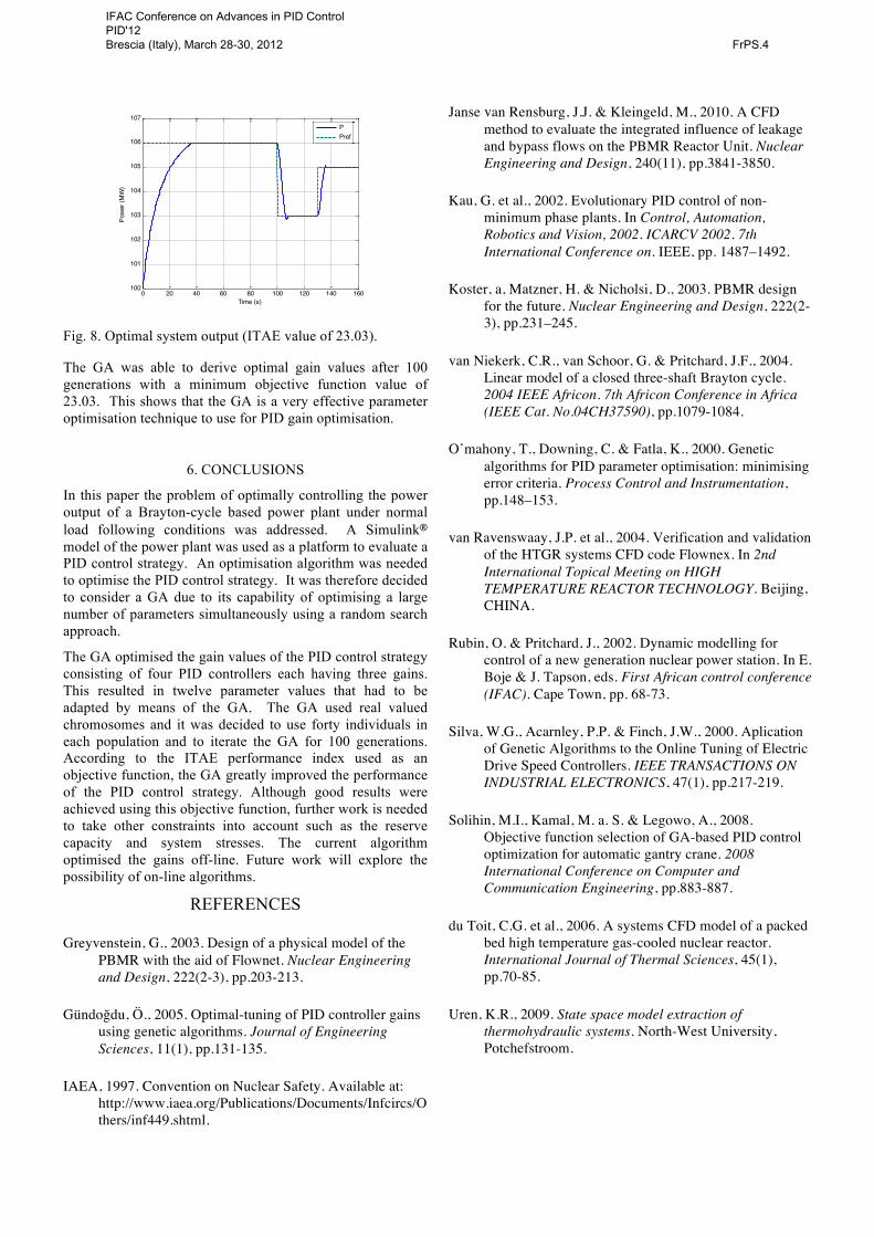
Fig. 8. Optimal system output (ITAE value of 23.03).
The GA was able to derive optimal gain values after 100 generations with a minimum objective function value of 23.03. This shows that the GA is a very effective parameter optimisation technique to use for PID gain optimisation.
6. CONCLUSIONS
In this paper the problem of optimally controlling the power output of a Brayton-cycle based power plant under normal load following conditions was addressed. A Simulink® model of the power plant was used as a platform to evaluate a PID control strategy. An optimisation algorithm was needed to optimise the PID control strategy. It was therefore decided to consider a GA due to its capability of optimising a large number of parameters simultaneously using a random search approach.
The GA optimised the gain values of the PID control strategy consisting of four PID controllers each having three gains. This resulted in twelve parameter values that had to be adapted by means of the GA. The GA used real valued chromosomes and it was decided to use forty individuals in each population and to iterate the GA for 100 generations. According to the ITAE performance index used as an objective function, the GA greatly improved the performance of the PID control strategy. Although good results were achieved using this objective function, further work is needed to take other constraints into account such as the reserve capacity and system stresses. The current algorithm optimised the gains off-line. Future work will explore the possibility of on-line algorithms.
REFERENCES
Greyvenstein, G., 2003. Design of a physical model of the PBMR with the aid of Flownet. Nuclear Engineering and Design, 222(2-3), pp.203-213.
Gündoğdu, Ö., 2005. Optimal-tuning of PID controller gains using genetic algorithms. Journal of Engineering Sciences, 11(1), pp.131-135.
IAEA, 1997. Convention on Nuclear Safety. Available at: http://www.iaea.org/Publications/Documents/Infcircs/Others/inf449.shtml.
Janse van Rensburg, J.J. & Kleingeld, M., 2010. A CFD method to evaluate the integrated influence of leakage and bypass flows on the PBMR Reactor Unit. Nuclear Engineering and Design, 240(11), pp.3841-3850.
Kau, G. et al., 2002. Evolutionary PID control of non-minimum phase plants. In Control, Automation, Robotics and Vision, 2002. ICARCV 2002. 7th International Conference on. IEEE, pp. 1487–1492.
Koster, a, Matzner, H. & Nicholsi, D., 2003. PBMR design for the future. Nuclear Engineering and Design, 222(2-3), pp.231–245.
van Niekerk, C.R., van Schoor, G. & Pritchard, J.F., 2004. Linear model of a closed three-shaft Brayton cycle. 2004 IEEE Africon. 7th Africon Conference in Africa (IEEE Cat. No.04CH37590), pp.1079-1084.
O’mahony, T., Downing, C. & Fatla, K., 2000. Genetic algorithms for PID parameter optimisation: minimising error criteria. Process Control and Instrumentation, pp.148–153.
van Ravenswaay, J.P. et al., 2004. Verification and validation of the HTGR systems CFD code Flownex. In 2nd International Topical Meeting on HIGH TEMPERATURE REACTOR TECHNOLOGY. Beijing, CHINA.
Rubin, O. & Pritchard, J., 2002. Dynamic modelling for control of a new generation nuclear power station. In E. Boje & J. Tapson, eds. First African control conference (IFAC). Cape Town, pp. 68-73.
Silva, W.G., Acarnley, P.P. & Finch, J.W., 2000. Aplication of Genetic Algorithms to the Online Tuning of Electric Drive Speed Controllers. IEEE TRANSACTIONS ON INDUSTRIAL ELECTRONICS, 47(1), pp.217-219.
Solihin, M.I., Kamal, M. a. S. & Legowo, A., 2008. Objective function selection of GA-based PID control optimization for automatic gantry crane. 2008 International Conference on Computer and Communication Engineering, pp.883-887.
du Toit, C.G. et al., 2006. A systems CFD model of a packed bed high temperature gas-cooled nuclear reactor. International Journal of Thermal Sciences, 45(1), pp.70-85.
Uren, K.R., 2009. State space model extraction of thermohydraulic systems. North-West University, Potchefstroom.
IFAC Conference on Advances in PID Control PID'12 Brescia (Italy), March 28-30, 2012 FrPS.4