Embed Size (px)
Citation preview
ADS
Ref. :
Issue :
Page :
ADS.E.0787
2 Rev. : 0
1 / 44
The copyright in this document is the property of EADS Astrium SAS/Ltd/GmbH and the contents may not be reproduced or revealed to third parties without prior permission of that company in writing.
Filename ADSE0787_issue2.doc
Generic Mechanical FEM Specification
The current issue is the electronic copy available through ADS on line. All paper copies are for information only.
ADS
Ref. :
Issue :
Page :
ADS.E.0787
2 Rev. : 0
2 / 44
The copyright in this document is the property of EADS Astrium SAS/Ltd/GmbH and the contents may not be reproduced or revealed to third parties without prior permission of that company in writing.
Filename ADSE0787_issue2.doc
CONTENTS
�
1� INTRODUCTION/APPLICABILITY..........................................................................................................6�
2� REFERENCE DOCUMENTATION...........................................................................................................8�
3� ACRONYMS.............................................................................................................................................9�
4� MODEL DATA AND IDENTIFICATION .................................................................................................10�
4.1� GENERAL INFORMATION .............................................................................................................10�
4.1.1� FEMR/01 Model identification..................................................................................................10�
4.1.2� FEMR/02 Linearity of the model ..............................................................................................10�
4.1.3� FEMR/03 Version of NASTRAN software ...............................................................................10�
4.1.4� FEMR/04 Model units ..............................................................................................................10�
4.2� BOUNDARIES CONDITION............................................................................................................10�
4.2.1� FEMR/05 Interface node label .................................................................................................10�
4.3� NUMBERING RANGE .....................................................................................................................11�
4.3.1� FEMR/06 Bulk data card numbering range .............................................................................11�
4.3.2� FEMR/07 Bulk data duplicate card ..........................................................................................11�
4.3.3� FEMR/08 Continuation card ....................................................................................................11�
4.4� COORDINATE SYSTEM .................................................................................................................11�
4.4.1� FEMR/09 Reference system....................................................................................................11�
4.4.2� FEMR/10 Local reference system ...........................................................................................11�
4.4.3� FEMR/11 Card referring to reference system..........................................................................11�
4.5� NASTRAN PARAMETERS..............................................................................................................11�
4.5.1� FEMR/12 Prohibited NASTRAN parameters...........................................................................12�
4.5.2� FEMR/13 Recommended NASTRAN parameters ..................................................................12�
4.5.3� FEMR/14 AUTOSPC parameter..............................................................................................13�
4.5.4� FEMR/15 Parameter affecting a set of data ............................................................................13�
4.6� PERMITTED AND PROHIBITED CARDS .......................................................................................13�
4.6.1� FEMR/16 Permitted NASTRAN card.......................................................................................13�
4.6.2� FEMR/17 Prohibited NASTRAN card ......................................................................................14�
4.7� NODES AND ELEMENTS ...............................................................................................................14�
4.7.1� FEMR/18 Free nodes ..............................................................................................................14�
4.7.2� FEMR/19 Nodes connecting CELAS.......................................................................................14�
4.7.3� FEMR/20 Spring elements.......................................................................................................14�
4.8� PROPERTIES..................................................................................................................................14�
4.8.1� FEMR/21 Material orientation..................................................................................................14�
4.8.2� FEMR/22 E, G and ν relation...................................................................................................15�
4.8.3� FEMR/23 Bar element orientation ...........................................................................................15�
4.8.4� FEMR/24 Mass distribution......................................................................................................15�
4.8.5� FEMR/25 Non-structural mass ................................................................................................15�
ADS
Ref. :
Issue :
Page :
ADS.E.0787
2 Rev. : 0
3 / 44
The copyright in this document is the property of EADS Astrium SAS/Ltd/GmbH and the contents may not be reproduced or revealed to third parties without prior permission of that company in writing.
Filename ADSE0787_issue2.doc
4.9� DAMPING ........................................................................................................................................15�
4.9.1� FEMR/26 Prohibited damping definition ..................................................................................15�
4.9.2� FEMR/27 Recommended damping definition..........................................................................15�
4.9.3� FEMR/28 Symmetry of the damping matrix.............................................................................15�
4.10� AIR EFFECTS..................................................................................................................................16�
4.10.1� FEMR/29 Air effect modelling..................................................................................................16�
5� CHECKS.................................................................................................................................................17�
5.1� BOUNDARY CONDITIONS.............................................................................................................17�
5.1.1� FEMR/30 Magnitude of seismic mass .....................................................................................17�
5.1.2� FEMR/31 Magnitude of interface load CELAS ........................................................................17�
5.2� STRAIN ENERGIES ........................................................................................................................18�
5.2.1� FEMR/32 Over constraint check..............................................................................................18�
5.2.2� FEMR/33 SUPORT strain energy............................................................................................19�
5.3� MAXRATIO ......................................................................................................................................19�
5.3.1� FEMR/34 Maxratio...................................................................................................................19�
5.4� FREE-FREE MODES ......................................................................................................................19�
5.4.1� FEMR/35 Number of free/free modes .....................................................................................19�
5.4.2� FEMR/36 Frequencies of rigid body modes ............................................................................19�
5.5� MASS PROPERTIES.......................................................................................................................19�
5.5.1� FEMR/37 Mass according to axes...........................................................................................19�
5.5.2� FEMR/38 Mass matrix at G, N, F and A set size.....................................................................20�
5.5.3� FEMR/39 Centre of gravity ......................................................................................................20�
5.6� GRAVITY CHECKS .........................................................................................................................20�
5.6.1� FEMR/40 Force balance..........................................................................................................20�
5.6.2� FEMR/41 Elements with zero load ..........................................................................................20�
5.7� DYNAMIC CHECKS ........................................................................................................................21�
5.7.1� FEMR/42 Low frequencies acceleration..................................................................................21�
6� TEMPERATURE LOADING CHECKS...................................................................................................22�
6.1� NASTRAN THERMOELASTIC METHODOLOGY...........................................................................22�
6.1.1� FEMR/44 Rotations and stresses under uniform temperature change ...................................22�
6.1.2� FEMR/45 Stress ratio for uniform temperature change...........................................................23�
6.1.3� FEMR/46 Rigid element in thermo-elastic models ..................................................................23�
6.1.4� FEMR/47 Thermo-elastic properties........................................................................................23�
7� ACCURACY OF FEM VERSUS HARDWARE ......................................................................................24�7.1.1� FEMR/48 Mass, inertia and centre of gravity accuracy...........................................................24�
7.1.2� FEMR/49 Dynamic accuracy ...................................................................................................24�
8� DELIVERABLES ....................................................................................................................................25�
8.1� FILES DELIVERED..........................................................................................................................25�
8.1.1� FEMR/50 Type of delivered files .............................................................................................25�
8.1.2� FEMR/51 Format of delivered files ..........................................................................................25�
8.1.3� FEMR/52 Data transfer media.................................................................................................25�
ADS
Ref. :
Issue :
Page :
ADS.E.0787
2 Rev. : 0
4 / 44
The copyright in this document is the property of EADS Astrium SAS/Ltd/GmbH and the contents may not be reproduced or revealed to third parties without prior permission of that company in writing.
Filename ADSE0787_issue2.doc
8.1.4� FEMR/53 Files identification....................................................................................................25�
8.2� NASTRAN INPUT FILES .................................................................................................................25�
8.2.1� FEMR/54 NASTRAN input files ...............................................................................................25�
8.2.2� FEMR/55 Use of alter ..............................................................................................................25�
8.2.3� FEMR/56 NASTRAN version...................................................................................................26�
8.3� NASTRAN BULK DATA...................................................................................................................26�
8.3.1� FEMR/57 NASTRAN bulk data................................................................................................26�
8.3.2� FEMR/58 Use of PARAM ........................................................................................................26�
8.3.3� FEMR/59 NASTRAN files for thermo elastic model ................................................................26�
8.3.4� FEMR/60 NASTRAN bulk data file organisation .....................................................................26�
8.3.5� FEMR/61 Analysis results........................................................................................................26�
8.4� MODEL DESCRIPTION REPORT...................................................................................................26�
8.4.1� FEMR/62 FEM description.......................................................................................................26�
8.4.2� FEMR/63 Report outline ..........................................................................................................27�
9� REDUCED MODEL CHECKS................................................................................................................29�
9.1� FEMR/64 SIZE REDUCTION ................................................................................................................29�
9.2� REDUCTION METHODS .......................................................................................................................29�
9.2.1� Selection criteria for reduction method ....................................................................................29�
9.2.2� FEMR/65 Reduction model – Grid documentation..................................................................30�
9.2.3� FEMR/66 Nastran DMAPs necessary for reduced model .......................................................30�
9.2.4� FEMR/67 Acceptance criteria for reduced models..................................................................30�
9.3� DYNAMIC REDUCTION MODEL ..............................................................................................................31�
9.3.1� FEMR/68 Dynamic reduction model – Guyan reduced model format .....................................31�
9.3.2� FEMR/69 Nastran DMAPs used for model condensation .......................................................31�
9.4� FEMR/70 REDUCED DISTORTION ANALYSIS MODELS ...........................................................................31�
9.5� FEMR/71 NASTRAN MATRICES........................................................................................................32�
10� GENERAL PRACTICES.........................................................................................................................33�
10.1� FREE BOUNDARIES.............................................................................................................................33�
10.2� COINCIDENT NODES ...........................................................................................................................33�
10.3� ELEMENT GEOMETRY .........................................................................................................................33�
10.3.1� Skew ........................................................................................................................................33�
10.3.2� Taper........................................................................................................................................33�
10.3.3� Aspect ratio ..............................................................................................................................34�
10.3.4� Warp ........................................................................................................................................34�
10.3.5� Element co-ordinate systems ..................................................................................................34�
10.3.6� Coincident elements ................................................................................................................34�
10.4� FLAT PLANE REFERENCE SYSTEM........................................................................................................35�
10.5� NASTRAN BULK DATA COMMENTS .....................................................................................................35�
10.6� EQUIPMENT MODELLING .....................................................................................................................35�
10.7� ENFORCED UNIT DISPLACEMENT AND ROTATION...................................................................................35�
10.8� DIAGONAL TERMS OF STIFFNESS MATRIX .............................................................................................36�
10.9� DFLR CHECK.....................................................................................................................................36�

ADS
Ref. :
Issue :
Page :
ADS.E.0787
2 Rev. : 0
5 / 44
The copyright in this document is the property of EADS Astrium SAS/Ltd/GmbH and the contents may not be reproduced or revealed to third parties without prior permission of that company in writing.
Filename ADSE0787_issue2.doc
10.10� WARNING MESSAGES .....................................................................................................................36�
10.11� MAGNITUDE OF SPCFORCE AT GRIDS CONSTRAINED BY AUTOSPC..............................................37�
10.12� VERIFICATION OF APPLIED DYNAMIC LOAD .......................................................................................37�
APPENDIX 1 – MODEL CHECKLIST FORM.................................................................................................38�
APPENDIX 2 – STRUCTURAL MODEL REDUCTION THEORY AND PROCEDURE.................................40�
CHANGE RECORD.........................................................................................................................................44�
ADS
Ref. :
Issue :
Page :
ADS.E.0787
2 Rev. : 0
6 / 44
The copyright in this document is the property of EADS Astrium SAS/Ltd/GmbH and the contents may not be reproduced or revealed to third parties without prior permission of that company in writing.
Filename ADSE0787_issue2.doc
1 INTRODUCTION/APPLICABILITY
This document provides the combination of requirements from the primary analysis groups within EADS
Astrium. In the event of conflict between the requirements defined in this document and customer
documentation the customer specification is applicable.
Requirements are defined for Finite Element Models, (FEM), used for different types of analysis, static and
dynamic. The supplier of the FEM is required to comply with the requirements applicable to the types of
analysis for which the model is to be used.
It is recommended that this document is used as an applicable document from which the appropriate
applicable requirements can be identified.
Adoption of good modelling practice at the start of modelling will generally reduce overall effort in terms of
compliancy with the requirements specified here-in. Examples of good modelling practice includes:
� Attention to defining GRID output displacement directions in local co-ordinate systems on obliquely
defined shell element meshes i.e. planar surfaces inclined to the basic or primary reference frame.
� Attention to CELAS GRID co-linearity and replicated GRID output displacement co-ordinate systems
on associated GRID pairs.
� Generation of true planar meshed surfaces (“flat surfaces”) for local shell element meshes.
REMEMBER: it is usually more cost effective in terms of time and effort to adopt good progressive modelling
practices than to rely on major wholesale corrections at the end of modelling!
The checks defined in the document are considered good practice for any analysis model and are
mandatory for finite element models:
� to be supplied by internal and external sub contractors.
� delivered to internal and external sub contractors.
� delivered to internal and external customers if no customer specification is defined.
The term supplier is used to identify the company providing the finite element model.
The term integrator is used to identify the company integrating the delivered model in subsequent analysis
activities.
These requirements identify checking requirements applicable to all finite element models for:
� FEM of complete satellite system,
� FEM of subsystems (solar arrays, propellant tanks, antenna systems…),
� FEM of equipments or instrumentation to be integrated into system model (electronic boxes,
processor units and feed systems…).
The FE models delivered by the supplier shall follow the general guidelines defined in this document. The
application of the requirements will allow full compatibility, integration and homogeneous quality of the
different models and consequently correct analysis/verification activities at system level. Within this
document, each technical requirement is given a unique reference number (FEMR) for supplier statement of
compliance or mandatory application by project documents or specifications.

ADS
Ref. :
Issue :
Page :
ADS.E.0787
2 Rev. : 0
7 / 44
The copyright in this document is the property of EADS Astrium SAS/Ltd/GmbH and the contents may not be reproduced or revealed to third parties without prior permission of that company in writing.
Filename ADSE0787_issue2.doc
These models are typically used for:
static analysis: to obtain deformations, load distribution, forces and moments of the total structure, structural
parts and key interfaces.
stress analyses: to obtain stress distributions to assess the structure or hardware with respect to yield,
ultimate and fatigue loading conditions.
dynamic analyses (incl. acoustic and micro-vibration analyses): to obtain eigenfrequencies, associated
mode shapes, amplification factors, dynamic loads, dynamic deformations at equipment, subsystem and
system level to assess dynamic behaviour with respect to launch vehicle requirements, on station
requirements and test predictions.
dimensional stability analysis: to determine the displacement of the satellite and subsystems with respect to
thermal and moisture environments for assessment of the implications of the distortion on the pointing
accuracy of communication equipment and Attitude Orbit Control System.

ADS
Ref. :
Issue :
Page :
ADS.E.0787
2 Rev. : 0
8 / 44
The copyright in this document is the property of EADS Astrium SAS/Ltd/GmbH and the contents may not be reproduced or revealed to third parties without prior permission of that company in writing.
Filename ADSE0787_issue2.doc
2 REFERENCE DOCUMENTATION
None
ADS
Ref. :
Issue :
Page :
ADS.E.0787
2 Rev. : 0
9 / 44
The copyright in this document is the property of EADS Astrium SAS/Ltd/GmbH and the contents may not be reproduced or revealed to third parties without prior permission of that company in writing.
Filename ADSE0787_issue2.doc
3 ACRONYMS
CAD : Computer aided design
CTE : Coefficient of thermal expansion
DOF : Degree of freedom
FE : Finite element
FEM : Finite element model
FEMR : Finite element requirement
RBE : Rigid body element
TED : Thermo elastic distortion
ADS
Ref. :
Issue :
Page :
ADS.E.0787
2 Rev. : 0
10 / 44
The copyright in this document is the property of EADS Astrium SAS/Ltd/GmbH and the contents may not be reproduced or revealed to third parties without prior permission of that company in writing.
Filename ADSE0787_issue2.doc
4 MODEL DATA AND IDENTIFICATION
4.1 GENERAL INFORMATION
4.1.1 FEMR/01 Model identification
A finite element model shall be assigned a unique identification name or number and refer to a configuration
of issue where possible.
For example this can be a mechanical interface control document of the equipment including mass, inertia
and centre of gravity or an issue of the system mass budget at key phases of the design, PDR, CDR...
4.1.2 FEMR/02 Linearity of the model
A full structural model shall be delivered using only linear elastic elements and properties.
4.1.3 FEMR/03 Version of NASTRAN software
All data in any delivered finite element definition shall be compatible with MSC MD NASTRAN Version 2006r1 unless an alternative is agreed with the integrator (e.g. prime contractor for a project).
When an alternative analysis code has been used the results must be correlated with the delivered
NASTRAN model.
4.1.4 FEMR/04 Model units
NASTRAN solver and associated pre/post processors have no preference for units it is the responsibility of
the analyst to ensure consistent units are used in the model.
All models shall be defined using S.I. units:
� Newton (N) for force
� Kilograms (kg) for mass
� Metres (m) for length
� Seconds (s) for time
� Degrees Celsius (°C) for temperature
with the derived units:
� E-modulus [Newton/meter²]
� density [kg/meter3]
4.2 BOUNDARIES CONDITION
4.2.1 FEMR/05 Interface node label
All model interfaces shall be representative of the physical attachment points of the items and shall be
modelled as independent points with appropriate degrees of freedom, typically six degrees of freedom.
The label of each interface node shall be clearly identified.
ADS
Ref. :
Issue :
Page :
ADS.E.0787
2 Rev. : 0
11 / 44
The copyright in this document is the property of EADS Astrium SAS/Ltd/GmbH and the contents may not be reproduced or revealed to third parties without prior permission of that company in writing.
Filename ADSE0787_issue2.doc
The following comments shall be included in the model:
� Interface grid points, identification and location,
� Boundary condition, clamped degrees of freedom,
� Grids included in the ASET or CSUPER when appropriate.
4.3 NUMBERING RANGE
4.3.1 FEMR/06 Bulk data card numbering range
Identification numbers of all NASTRAN cards (e.g. nodes, elements, coordinate systems, material
properties...) shall be in accordance with any specified numbering range defined by the integrator. A record
of identities, quantities of elements and grids associated with all parts of the FEM shall be kept. This will
assist in error tracing during the completion of constraint and conditioning checks.
4.3.2 FEMR/07 Bulk data duplicate card
No duplicate node or element identification numbers shall exist in the model.
4.3.3 FEMR/08 Continuation card
The continuation card should be written with “+” or “*” symbol. If a number is used in the continuation card, it
must be the card ID number. For instance “+E120000” continuation card is only authorised for element n°
120000.
4.4 COORDINATE SYSTEM
4.4.1 FEMR/09 Reference system
One primary rectangular right handed reference system shall be defined by the supplier as for the sub
model.
4.4.2 FEMR/10 Local reference system
All local reference systems shall be related to this primary reference system.
4.4.3 FEMR/11 Card referring to reference system
All NASTRAN cards using reference systems (e.g. GRID, CONM2, etc.) shall be defined with respect to the
primary reference system or a local reference system i.e. the use of the default identification number "0" is
not allowed.
4.5 NASTRAN PARAMETERS
NASTRAN has available a number of parameters to provide some options on how the model is processed.
ADS
Ref. :
Issue :
Page :
ADS.E.0787
2 Rev. : 0
12 / 44
The copyright in this document is the property of EADS Astrium SAS/Ltd/GmbH and the contents may not be reproduced or revealed to third parties without prior permission of that company in writing.
Filename ADSE0787_issue2.doc
4.5.1 FEMR/12 Prohibited NASTRAN parameters
The following Parameters are not to be used: � BAILOUT, -1 � MAXRATIO � EPZERO � WTMASS � MECHFIX,YES
The use of other default values in version 2006 shall be agreed with the prime
4.5.2 FEMR/13 Recommended NASTRAN parameters
The following parameters shall be used with the specified value:
� BAILOUT, 0 � K6ROT, 100.0 � SNORM, 20.0 � MECHFIX, NO
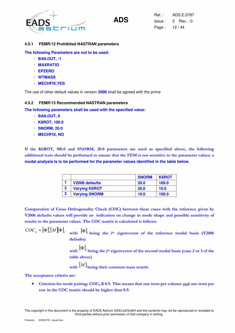
��� ���� ����� ����� ���� ����� ����� ����������� ���� ����� ��� ���������� ��� ��� ���� ��!!�"��#�
���������!�����������!����������������������������������$%���������������� ������������������� �!���&��
modal analysis is to be performed for the parameter values identified in the table below.
SNORM K6ROT 1 V2006 defaults 20.0 100.0 2 Varying K6ROT 20.0 10.0 3 Varying SNORM 10.0 100.0
�
'��������������'���������#���!��(�'���)�*''+����"���� ������������"���� ���� ����������#� ����(�
,����������!��� �!����"�!!���� ��������������������������#��������������������������!��������� ��(����
����!�������������������� �!���������''������-������!��!����������!!�"�&�
[ ] [ ][ ] ��
��� ���� ΦΦ=�� "���� [ ]�Φ ����#� ���� ���� ��#�� ������ ��� ���� ���������� ����!� ������ *,�����
�����!��+�
� "����[ ] �Φ
����#�����.�����#�� ������������������������!�������*����������/��������
���!����� �+��
� "���� [ ]� ����#������������������������-�
���������������������������&�
•••• '������������������������#&�''�.�����0���������������������������������!���������������������
��"��������''������-�����!�������#�����������0��
ADS
Ref. :
Issue :
Page :
ADS.E.0787
2 Rev. : 0
13 / 44
The copyright in this document is the property of EADS Astrium SAS/Ltd/GmbH and the contents may not be reproduced or revealed to third parties without prior permission of that company in writing.
Filename ADSE0787_issue2.doc
•••• 1���������� ���������&� ���2����(� ������ ��� ������� ������ �� 3�� ����� ������ ����� ���� ������ ���
���2����(�"���������(��#���������������� �!�������!�����!�"�������� 3���)��#������
������������������!��������� �������#� ����(������������#������ �������#�����''�����������
�������������������������#�������������������������������������������������!��!!�����.����������������!!����
��� ������
The use of other default values in version 2006 shall be agreed with the prime
4.5.3 FEMR/14 AUTOSPC parameter
When a permanent single point constraint set has been generated from AUTOSPC,YES this set must be
kept separate from the model boundary constraint set (i.e. different SPC card, same SPC set allowed) and
is part of the definition of the model so must be provided to the integrator.
4.5.4 FEMR/15 Parameter affecting a set of data
Any input specification, which can affect the data of other models when merged, may not be used without
agreement of the integrator. For example assigning a value of greater than 0 for PARAM, COUPMASS
invokes the creation of the coupled mass matrix which can lead to different frequencies compared to the use
of the lumped mass matrix.
4.6 PERMITTED AND PROHIBITED CARDS
4.6.1 FEMR/16 Permitted NASTRAN card
The following NASTRAN cards are permitted:
COORDINATE SYSTEMS CORD2R, CORD2C, CORD2S
NODES GRID, SPOINT
1D ELEMENTS CROD, CBAR, CBEAM
2D ELEMENTS CTRIA3, CQUAD4
3D ELEMENTS CPENTA, CTETRA, CHEXA
CONCENTRATED MASSES CONM2
INTERFACES SPRINGS CELAS1, CELAS2,CBUSH
RIGID ELEMENTS MPC, RBAR & RBE2, RBE3
OTHERS PLOTEL, DMIG, GENEL
BOUNDARY CONDITIONS SPC, SPC1
PROPERTIES Any linear properties
Figure 4-1 – Permitted model inputs
ADS
Ref. :
Issue :
Page :
ADS.E.0787
2 Rev. : 0
14 / 44
The copyright in this document is the property of EADS Astrium SAS/Ltd/GmbH and the contents may not be reproduced or revealed to third parties without prior permission of that company in writing.
Filename ADSE0787_issue2.doc
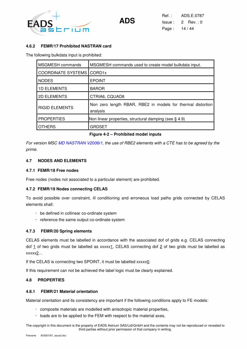
4.6.2 FEMR/17 Prohibited NASTRAN card
The following bulkdata input is prohibited:
MSGMESH commands MSGMESH commands used to create model bulkdata input.
COORDINATE SYSTEMS CORD1x
NODES EPOINT
1D ELEMENTS BAROR
2D ELEMENTS CTRIA6, CQUAD8
RIGID ELEMENTS Non zero length RBAR, RBE2 in models for thermal distortion
analysis
PROPERTIES Non linear properties, structural damping (see § 4.9)
OTHERS GRDSET
Figure 4-2 – Prohibited model inputs
For version MSC MD NASTRAN V2006r1, the use of RBE2 elements with a CTE has to be agreed by the
prime.
4.7 NODES AND ELEMENTS
4.7.1 FEMR/18 Free nodes
Free nodes (nodes not associated to a particular element) are prohibited.
4.7.2 FEMR/19 Nodes connecting CELAS
To avoid possible over constraint, ill conditioning and erroneous load paths grids connected by CELAS
elements shall:
� be defined in collinear co-ordinate system
� reference the same output co-ordinate system
4.7.3 FEMR/20 Spring elements
CELAS elements must be labelled in accordance with the associated dof of grids e.g. CELAS connecting
dof 1 of two grids must be labelled as xxxxx1, CELAS connecting dof 2 of two grids must be labelled as
xxxxx2…
If the CELAS is connecting two SPOINT, it must be labelled xxxxx0.
If this requirement can not be achieved the label logic must be clearly explained.
4.8 PROPERTIES
4.8.1 FEMR/21 Material orientation
Material orientation and its consistency are important if the following conditions apply to FE models:
� composite materials are modelled with anisotropic material properties,
� loads are to be applied to the FEM with respect to the material axes,
ADS
Ref. :
Issue :
Page :
ADS.E.0787
2 Rev. : 0
15 / 44
The copyright in this document is the property of EADS Astrium SAS/Ltd/GmbH and the contents may not be reproduced or revealed to third parties without prior permission of that company in writing.
Filename ADSE0787_issue2.doc
� element forces or stresses are to be extracted with respect to material axes.
All material orientation angles shall be defined using local co-ordinate system(s). Defining material
orientation angles with respect to element geometry is forbidden (distorted elements can introduce errors in
the material orientation angle definition, while the local co-ordinate system permit precise definition of the
material orientation angle).
Most pre processors have facilities for showing element material axes and subsequently aligning them to a
particular coordinate system.
4.8.2 FEMR/22 E, G and νννν relation
For MAT1, only two of the three values of E, G and ν must be filled except if this is coherent with the relation
: ( )ν+=
1.2E
G
This should eliminate warning message 2251 associated with inconsistent values for E, G and ν.
4.8.3 FEMR/23 Bar element orientation
The orientation of linear elements, bars and beams, require the definition of an orientation vector. The
orientation shall be defined by the specification of components of the orientation vector. The use of a grid
point to define the element orientation is not permitted.
4.8.4 FEMR/24 Mass distribution
Where practical the density field of the appropriate MAT card shall be used to define structural mass. This
should be representative of the material considered.
4.8.5 FEMR/25 Non-structural mass
Non-structural masses shall be spread over the structure via NSM field of property cards or as specific
lumped mass using CONM2 elements. Variation of material mass density to simulate distributed non-
structural masses shall be avoided.
4.9 DAMPING
4.9.1 FEMR/26 Prohibited damping definition
Any viscous damping elements are to be avoided unless they are inherent in the design. Specification of
damping on CELAS, CBUSH and MAT cards is generally prohibited. In exceptional circumstances (with the
prime’s agreement), where material/element based structural damping needs to be specified, the supplier
shall clearly identify and justify the specification of damping on any element or material input data.
4.9.2 FEMR/27 Recommended damping definition
When the FEM has been used for dynamic response analysis the supplier has to provide the critical modal
damping versus frequency (NASTRAN TABDMP1 input data), in the technical description document.
4.9.3 FEMR/28 Symmetry of the damping matrix
If a damping matrix is provided it shall be a symmetric.

ADS
Ref. :
Issue :
Page :
ADS.E.0787
2 Rev. : 0
16 / 44
The copyright in this document is the property of EADS Astrium SAS/Ltd/GmbH and the contents may not be reproduced or revealed to third parties without prior permission of that company in writing.
Filename ADSE0787_issue2.doc
4.10 AIR EFFECTS
4.10.1 FEMR/29 Air effect modelling
If it necessary to include the effect of air in the FE model (solar arrays or reflectors for example), the supplier
shall provide a clear description of the method of idealisation. The added mass shall be clearly identified
and modal analyses are to be provided with and without air effect.
ADS
Ref. :
Issue :
Page :
ADS.E.0787
2 Rev. : 0
17 / 44
The copyright in this document is the property of EADS Astrium SAS/Ltd/GmbH and the contents may not be reproduced or revealed to third parties without prior permission of that company in writing.
Filename ADSE0787_issue2.doc
5 CHECKS
5.1 BOUNDARY CONDITIONS
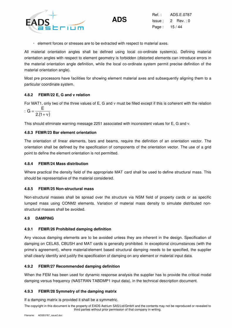
5.1.1 FEMR/30 Magnitude of seismic mass
For sine and random analysis the large mass method is often used. A mass much greater than the mass of
the structure being excited is used to achieve fixed base modes of vibration and to provide a scaling factor
for base force input.
The magnitude of the seismic mass required to represent the fixed base condition can be verified by
comparing the frequencies and effective model mass obtained from processing the model with fixed base
boundary conditions constrained defined by SPC’s and with the seismic mass with SUPORT specification.
f1
�
M
m
k
� m
k
f2
The objective is to have differences on the eigenfrequencies (f1, f2) of the two models less than 0.1%.
As a guide, seismic masses should be of the order of 10 5 to 10 7 times the mass of model and inertias
about the excitation reference point.
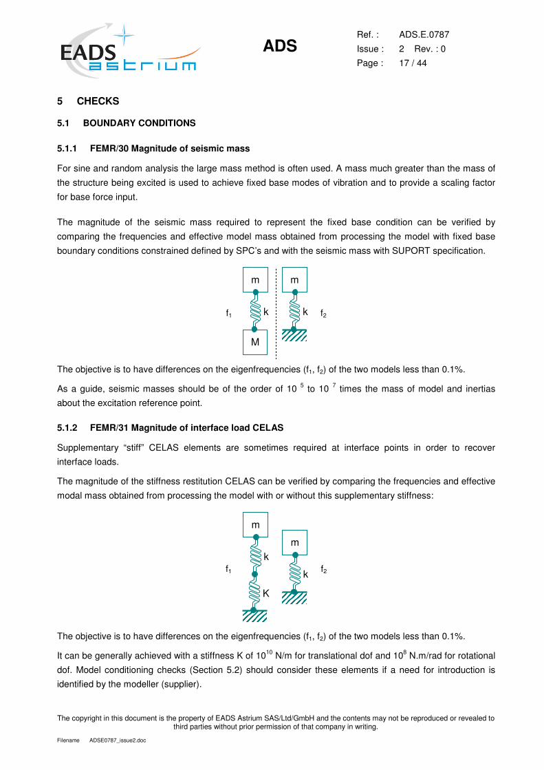
5.1.2 FEMR/31 Magnitude of interface load CELAS
Supplementary “stiff” CELAS elements are sometimes required at interface points in order to recover
interface loads.
The magnitude of the stiffness restitution CELAS can be verified by comparing the frequencies and effective
modal mass obtained from processing the model with or without this supplementary stiffness:
f1
� m
k
K
� m
k
f2
The objective is to have differences on the eigenfrequencies (f1, f2) of the two models less than 0.1%.
It can be generally achieved with a stiffness K of 1010 N/m for translational dof and 108 N.m/rad for rotational
dof. Model conditioning checks (Section 5.2) should consider these elements if a need for introduction is
identified by the modeller (supplier).
ADS
Ref. :
Issue :
Page :
ADS.E.0787
2 Rev. : 0
18 / 44
The copyright in this document is the property of EADS Astrium SAS/Ltd/GmbH and the contents may not be reproduced or revealed to third parties without prior permission of that company in writing.
Filename ADSE0787_issue2.doc
In addition, it should be verified that the stiffness is not too high for the restitution load in this CELAS by
applying unit acceleration vector (1 m/s2) independently in each axis.
This check should confirm that the load in the CELAS is equal to the mass of the specimen.
5.2 STRAIN ENERGIES
5.2.1 FEMR/32 Over constraint check
The purpose of the constraint check is to verify the model includes no automatically created or unintentional
constraints that will have an effect on the internal loads or rigid body behaviour.
This verification can be made with the NASTRAN GROUNDCHECK parameter (available since version
2001 of MSC/NASTRAN of version 1.0 of NX/NASTRAN). The model is constrained by specification of
sufficient degrees of freedom to eliminate rigid body motion via a SUPORT bulkdata input. Where possible
the constraint conditions should be representative of those to be used in subsequent analyses.
The results of this check reported in the.f06 file include four matrices, called KRBi. These are calculated
from the stiffness matrix and a rigid body vector based on the geometry of the model:
[KRBi]= [φ]T [K] [φ] (Joules)
Where [K] is the stiffness matrix and [φ] a rigid body mode vector calculated from the model geometry. This
product is equivalent to twice the strain energy.
Matrix KRBi are performed at various model sizes:
� G set (KRBG matrix): all structural degrees of freedom,
� N set (KRBN matrix): all structural degrees of freedom after implementation of multi-point constraint
relationships,
� F set (KRBF matrix): all unconstrained (free) degrees of freedom, after applications of all constraints,
� A set (KRBA matrix): analysis set.
The resultant matrixes KRBi are equal to twice the strain energy in the structure following its motion as a
rigid body. With SI units the six terms on the diagonal of the respective energy matrix, KRBi, shall be:
� G set: less than 1.0E-2 J
� N set: less than 1.0E-2 J
� F set: less than 1.0E-2 J for translational dof and 5.0 x 1.0E-2 J for rotational dof
� A set: less than 1.0E-2 J for translational dof and 5.0 x 1.0E-2 J for rotational dof
In the event the supplier is unable to meet these limits, Prime will require a justification for the reasons why
these limits are not met with a sound rationale for the acceptability of the FE model. The scope of
justification depends primarily on the magnitude of deviation between the achieved 2*Strain Energy levels
versus the above limits. The supplier may be required to justify the acceptability of the FE model with:
� Identification of offending locations within the model where constraints are generated
� Identification of the strain energy at F and A levels with PARAM,K6ROT,1 and identification of
offending locations in that case.
� A full comparison of the fixed based modes and effective masses with the model in its over
constrained state versus a similar fixed base state with PARAM,K6ROT,1. (for indication)
� A comparison of the first eight (8) free-free modes with no SUPORT card.
ADS
Ref. :
Issue :
Page :
ADS.E.0787
2 Rev. : 0
19 / 44
The copyright in this document is the property of EADS Astrium SAS/Ltd/GmbH and the contents may not be reproduced or revealed to third parties without prior permission of that company in writing.
Filename ADSE0787_issue2.doc
5.2.2 FEMR/33 SUPORT strain energy
This check uses the strain energy to confirm acceptable mathematical conditioning of internal loads of the
model.
This check is made with a classical NASTRAN dynamic analysis (SOL 103) with the model constrained
using SUPORT input data. The strain energy is calculated and given in the "*.f06" file at every support point.
The value of the strain energy must be less than or equal to 5.0 x 10⁻² J.
5.3 MAXRATIO
5.3.1 FEMR/34 Maxratio
The maximum ratio represents the ratio between the higher and the lower value of the stiffness matrix. If the
value of MAXRATIO is greater than the NASTRAN default value (107 in version 2001) an error message is
printed. If the value is less than the default value, this is not reported within the NASTRAN solution
sequence.
The value of MAXRATIO must be less than 107. In the event the supplier is unable to meet this criterion, a
justification shall be provided.
5.4 FREE-FREE MODES
The purpose of the "free-free" check is to verify the rigid body modes of the model.
This verification is made with a NASTRAN SOL 103 dynamic analysis with the model in free-free conditions,
i.e. no constraint specified by SPC or SUPORT input.
5.4.1 FEMR/35 Number of free/free modes
The number of rigid body modes must be 6. Supplementary rigid body modes (such as mechanisms) shall
be justified on a case-by-case basis.
5.4.2 FEMR/36 Frequencies of rigid body modes
The ratio of greatest rigid body frequency to the frequency of the first elastic mode must be less than 10-4.
5.5 MASS PROPERTIES
5.5.1 FEMR/37 Mass according to axes
The mass distribution check performed with respect to the NASTRAN “Grid Point Weight Generator
(GPWG)” provides:
� mass matrix of the structure (M0) at a reference point defined by PARAM GRDPNT,
� mass of the structure and position of the centre of gravity with respect to the reference point in the
primary local coordinate system,
� inertia matrix at the centre of gravity and in the primary local coordinate system of the reference
point [I(S)] or in the principal axis of inertia [I(Q)],
� the reference frame transformation matrix (Q), between the local coordinate system of the reference
point and the principal axis of inertia, the matrix of direction cosines.
ADS
Ref. :
Issue :
Page :
ADS.E.0787
2 Rev. : 0
20 / 44
The copyright in this document is the property of EADS Astrium SAS/Ltd/GmbH and the contents may not be reproduced or revealed to third parties without prior permission of that company in writing.
Filename ADSE0787_issue2.doc
Mass figures shall be the same for axes X, Y and Z. The centre of gravity location should correspond with
unit level budget estimates or the appropriate ICD to within 5%. If this is not the case differences shall be
justified.
5.5.2 FEMR/38 Mass matrix at G, N, F and A set size
The integrity of the mass matrix shall be checked at the NASTRAN G, N, F and A set size.
The rigid body mass matrix shall be determined:
[MRBi]= [φ]T [M] [φ]
Where [M] is the mass matrix and [φ] a rigid body vector calculated from the model geometry.
Any change in the terms of the mass matrix at each set shall be recorded.
5.5.3 FEMR/39 Centre of gravity
The mass distribution check performed with respect to the NASTRAN “Grid Point Weight Generator
(GPWG)” provides notably the position of the centre of gravity with respect to the reference point in the
primary local coordinate system.
Diagonal terms of the centre of gravity matrix must be less than 10-6 SI.
The two other terms (successively for each direction) must be equal.
5.6 GRAVITY CHECKS
5.6.1 FEMR/40 Force balance
The purpose of the static load check is to confirm that total forces at the interface of the model balances with
the applied load. The reaction forces for all loads analysed, gravity vector, point load or thermal load, shall
be checked to confirm they are at expected locations and that the forces and moments balance the applied
load.
For a model with a mass distribution the application of unit acceleration vector (1 m.s-2) independently in
each axis can be used to confirm that the sum of the constraint forces divided by the applied acceleration
equals the unit/model mass.
Interface reaction forces should be computed using the NASTRAN command SPCFORCES=ALL.
NASTRAN provides in the f06 output file the RESULTANT LOAD, the sum of the applied loads at the
GPWG reference point; the default is the origin of the basic coordinate system. The RESULTANT
SPCFORCES, the sum of the SPCFORCES is also provided.
For unit acceleration vectors (1 m/s2) the force in Newtons must be equal to the mass in kilograms.
5.6.2 FEMR/41 Elements with zero load
The model constraint checks, conditioning checks and free-free modes checks do not confirm correct
connectivity of all load paths.
Confirmation that valid load paths have not been omitted can be identified by identifying elements with zero
load.

ADS
Ref. :
Issue :
Page :
ADS.E.0787
2 Rev. : 0
21 / 44
The copyright in this document is the property of EADS Astrium SAS/Ltd/GmbH and the contents may not be reproduced or revealed to third parties without prior permission of that company in writing.
Filename ADSE0787_issue2.doc
An applied load representative of that to be used in analysis, gravity vector, point load or thermal load shall
be applied to the model. Appropriate Element output data, loads or stresses, shall be obtained and
processed to identify elements (CELAS, RBE, CTRIA, CQUAD, BAR, BEAM…) with zero load.
The number of elements with zero load must be null. The occurence of elements with zero load or stress
shall be identified and if appropriate justified.
5.7 DYNAMIC CHECKS
5.7.1 FEMR/42 Low frequencies acceleration
For dynamic analyses purpose, it should be verified that the behaviour at low frequencies is correct. The
application of unit acceleration vector (1 m.s-2) at low frequencies (near 0 Hz) independently in each axis
shall be used to confirm that the sum of the constraint forces divided by the model mass is at least equal to
95 % of the applied acceleration.
Values less than 95 % shows that the modal basis has not been calculated with sufficient modes. It can be
corrected with the PARAM, RESVEC or with a modal basis with more modes.
ADS
Ref. :
Issue :
Page :
ADS.E.0787
2 Rev. : 0
22 / 44
The copyright in this document is the property of EADS Astrium SAS/Ltd/GmbH and the contents may not be reproduced or revealed to third parties without prior permission of that company in writing.
Filename ADSE0787_issue2.doc
6 TEMPERATURE LOADING CHECKS
To check that the model is suitable for thermal distortion analysis a two checks are performed.
A model for thermal distortion analysis must have all RBAR and RBE2 elements of a finite length removed
or replaced with stiff bar elements with representative material properties and expansion coefficients. Rigid
body elements connecting coincident grids and RBE3 elements are acceptable.
For version MSC MD NASTRAN V2006r1, the use of RBE2 elements with a CTE has to be agreed by the
prime.
6.1 NASTRAN THERMOELASTIC METHODOLOGY
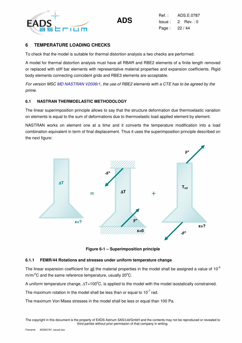
The linear superimposition principle allows to say that the structure deformation due thermoelastic variation
on elements is equal to the sum of deformations due to thermoelastic load applied element by element.
NASTRAN works on element one at a time and it converts the temperature modification into a load
combination equivalent in term of final displacement. Thus it uses the superimposition principle described on
the next figure:
�
∆∆∆∆T�
x=?�
=
�
∆∆∆∆T�
F∗∗∗∗�
-F∗∗∗∗�
x=0�
+
�
Tref
F∗∗∗∗�
-F∗∗∗∗�
x=?�
Figure 6-1 – Superimposition principle
6.1.1 FEMR/44 Rotations and stresses under uniform temperature change
The linear expansion coefficient for all the material properties in the model shall be assigned a value of 10-5
m/m/oC and the same reference temperature, usually 20oC.
A uniform temperature change, ∆T=100oC, is applied to the model with the model isostatically constrained.
The maximum rotation in the model shall be less than or equal to 10-7 rad.
The maximum Von Mises stresses in the model shall be less or equal than 100 Pa.
ADS
Ref. :
Issue :
Page :
ADS.E.0787
2 Rev. : 0
23 / 44
The copyright in this document is the property of EADS Astrium SAS/Ltd/GmbH and the contents may not be reproduced or revealed to third parties without prior permission of that company in writing.
Filename ADSE0787_issue2.doc
Any non-compliance with the criteria shall be identified and justified with respect to potential impact on
results of the distortion analysis.
6.1.2 FEMR/45 Stress ratio for uniform temperature change
When the results from the free expansion check, FEMR/44 are non-compliant it is necessary to perform a
second check to assess the magnitude of the stresses.
For this check the nodal loads from FEMR/44 are applied to the structure in combination with a uniform
temperature of 20oC with a reference temperature of 20oC (∆T=0oC). This is equivalent to applying the first
thermal case with all grids constrained. The ratio of Von Mises stress in FEMR/44 case to the Von Mises
stress in FEMR45/case provides an indication of the severity of the FEMR/44 case stresses.
The ratio of the stress 2
1
σσσσσσσσ
shall be less than or equal to 10-5.
6.1.3 FEMR/46 Rigid element in thermo-elastic models
The RBE2 and RBAR elements of finite length will need to be replaced by stiff bar elements for thermal
distortion analyses. CBAR and CBEAM cards must not be offset.
For version MSC MD NASTRAN V2006r1, the use of RBE2 elements with a CTE has to be agreed by the
prime.
6.1.4 FEMR/47 Thermo-elastic properties
All properties necessary for thermo-elastic analysis applications shall be specified, e.g. Coefficient of
Thermal Expansion and reference temperature.

ADS
Ref. :
Issue :
Page :
ADS.E.0787
2 Rev. : 0
24 / 44
The copyright in this document is the property of EADS Astrium SAS/Ltd/GmbH and the contents may not be reproduced or revealed to third parties without prior permission of that company in writing.
Filename ADSE0787_issue2.doc
7 ACCURACY OF FEM VERSUS HARDWARE
7.1.1 FEMR/48 Mass, inertia and centre of gravity accuracy
The accuracy of the model versus the equipment hardware (*) shall be:
� 1% for the mass,
� 5% for the moments of inertia,
� 1% of the maximum distance for the centre of gravity versus substructure I/F.
(*) The reference for accuracy should be the appropriate ICD relevant to the project or a delivered
system budget. The latter should be taken as the reference in the absence of weighed data e.g.
early study work, PDR stage etc. On the production of hardware the reference for accuracy should
be the weighed item.
7.1.2 FEMR/49 Dynamic accuracy
Dynamic accuracy of the FEM versus the hardware shall be computed when experimental modal testing has
been performed. Error shall be lower than:
� 20 % for static or thermo-elastic displacements,
� 5 % for main frequencies(1) of the item in test configuration,
� 20 % for significant responses performed during tests.
(1) Main frequencies means that the model effective mass has more than 5 % of the rigid mass of the item
involved.
ADS
Ref. :
Issue :
Page :
ADS.E.0787
2 Rev. : 0
25 / 44
The copyright in this document is the property of EADS Astrium SAS/Ltd/GmbH and the contents may not be reproduced or revealed to third parties without prior permission of that company in writing.
Filename ADSE0787_issue2.doc
8 DELIVERABLES
Effort shall be made in order to obtain, to the maximum extent, a unique model for covering the entire scope
of analyses (i.e. modal, statics…).
The following chapter describes the information that must be delivered to the prime contractor.
8.1 FILES DELIVERED
8.1.1 FEMR/50 Type of delivered files
The model files to be delivered are:
� NASTRAN input files,
� NASTRAN bulk data,
� modal analysis with representative boundaries condition (.f06 summary of eigen-frequency listing
etc),
� NASTRAN matrices (including KAA, MAA, ATM, DTM, LTMs for Craig Bampton reduced models) if
needed,
� NASTRAN partitioning vector (for correlation of matrices values to dof) if needed.
8.1.2 FEMR/51 Format of delivered files
All data files shall be in ASCII format.
8.1.3 FEMR/52 Data transfer media
The model data can be delivered in the following media:
� e-mail with ASCII or compressed files compatible with Windows or Unix executable (for example,
pkzip.exe or arj.exe, compress or gzip),
� CD ROM,
� DVD ROM.
8.1.4 FEMR/53 Files identification
The model name, issue and date shall be clearly specified.
A brief summary of all delivered files will be appreciated.
8.2 NASTRAN INPUT FILES
8.2.1 FEMR/54 NASTRAN input files
NASTRAN input files (containing the executive and case control section) shall be supplied for all analysis
types. These shall be supplied as separate bulk data run files.
8.2.2 FEMR/55 Use of alter
If NASTRAN written DMAP ALTERS are used the name and all used parameters shall be supplied and
described.
ADS
Ref. :
Issue :
Page :
ADS.E.0787
2 Rev. : 0
26 / 44
The copyright in this document is the property of EADS Astrium SAS/Ltd/GmbH and the contents may not be reproduced or revealed to third parties without prior permission of that company in writing.
Filename ADSE0787_issue2.doc
8.2.3 FEMR/56 NASTRAN version
The version and vendor of NASTRAN used shall be declared in the header of the file.
8.3 NASTRAN BULK DATA
8.3.1 FEMR/57 NASTRAN bulk data
NASTRAN bulk data files shall be delivered for all analysis types.
8.3.2 FEMR/58 Use of PARAM
All the PARAM cards required to run the model must be included.
8.3.3 FEMR/59 NASTRAN files for thermo elastic model
For the thermo elastic model the complete set of bulk data cards for the zero stress test shall be delivered.
8.3.4 FEMR/60 NASTRAN bulk data file organisation
To aid interpretation and management of FEM data the bulk data should be divided into several files, each
containing specific FEM data, basic geometry, interface grids, properties, and boundary conditions for
example.
As a minimum the filename structure shall include the FEM identification and nature of file content.
The following scheme is suggested but not mandatory:
� *_GEO.bdf : GEOmetry: nodes, elements (except those included in *.BIF file), RBE…,
� *_IF.bdf : InterFace: IF nodes and elements connecting the * item with other structures,
� *_CORD.bdf : CORDinate systems,
� *_PRO.bdf : PROperties and materials for all analyses,
� *_TEM.bdf : TEMperatures,
� *_LOA.bdf : LOAds and forces used for the analyses,
� *_SPC.bdf : Single point constraints for the different analysis,
The symbol * stands for the FEM name.
For the most complex items a further sub-division into sub-structures may be performed. Whichever file
organisation is chosen, it shall be briefly explained (a file INDEX.TXT is suggested).
8.3.5 FEMR/61 Analysis results
Extracts from the NASTRAN f06 output files appropriate to the model checks shall be reported in the model
description report and may also be delivered with model data files.
8.4 MODEL DESCRIPTION REPORT
8.4.1 FEMR/62 FEM description
The finite element model description report shall be written in English.
ADS
Ref. :
Issue :
Page :
ADS.E.0787
2 Rev. : 0
27 / 44
The copyright in this document is the property of EADS Astrium SAS/Ltd/GmbH and the contents may not be reproduced or revealed to third parties without prior permission of that company in writing.
Filename ADSE0787_issue2.doc
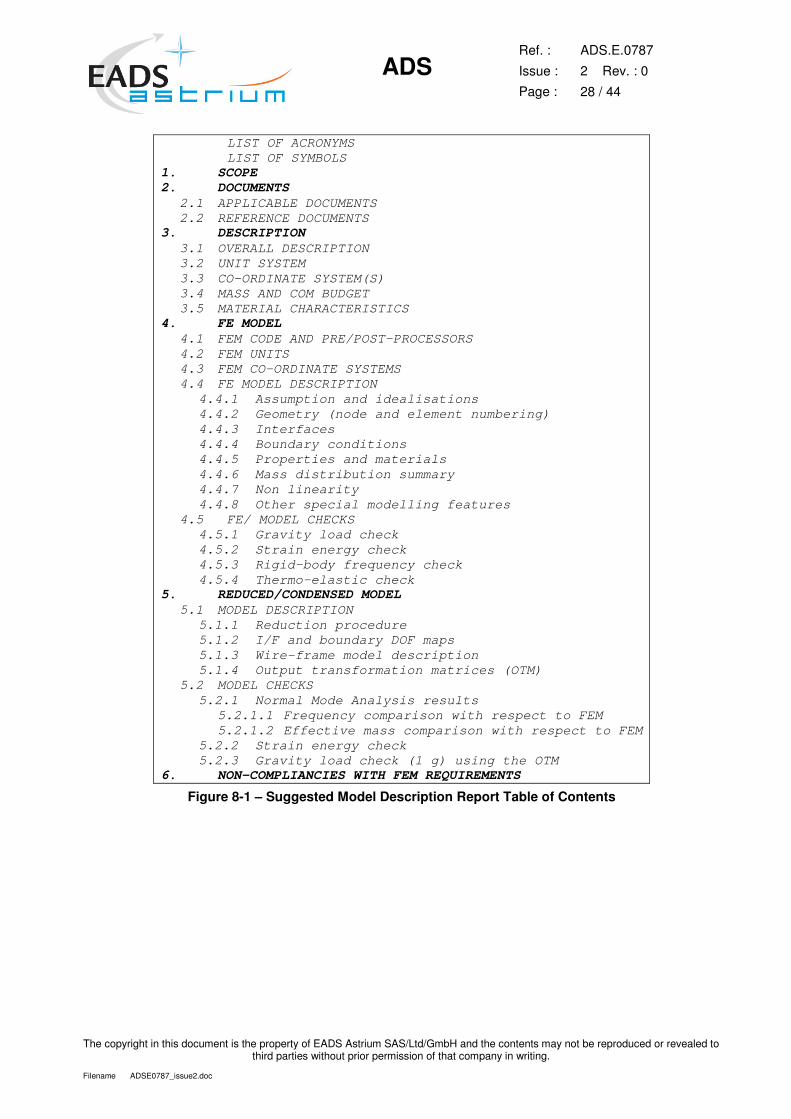
8.4.2 FEMR/63 Report outline
The FEM report shall define as a minimum the model designation, properties, mass distribution, modelling of
all parts that the integrator needs to reference, attach to, adapt on integration to system level and results of
the model checks performed.
Figure 8-1 provides a suggested list of the subjects in the model description report that should satisfy the
integrator and requirements of higher level customer.
A sketch of the co-ordinate system(s) associated with the primary appendages should be provided. In
general, all input data used for the model shall be clearly documented. Detailed plots of the model clearly
showing all nodes, elements, and connectivity of primary interfaces (and relevant numbering and types)
shall be supplied.
Pre – run checks successful completion shall be declared.
Post – run checks results shall be clearly documented.
ADS
Ref. :
Issue :
Page :
ADS.E.0787
2 Rev. : 0
28 / 44
The copyright in this document is the property of EADS Astrium SAS/Ltd/GmbH and the contents may not be reproduced or revealed to third parties without prior permission of that company in writing.
Filename ADSE0787_issue2.doc
LIST OF ACRONYMS LIST OF SYMBOLS 1. SCOPE 2. DOCUMENTS
2.1 APPLICABLE DOCUMENTS 2.2 REFERENCE DOCUMENTS
3. DESCRIPTION 3.1 OVERALL DESCRIPTION 3.2 UNIT SYSTEM 3.3 CO-ORDINATE SYSTEM(S) 3.4 MASS AND COM BUDGET 3.5 MATERIAL CHARACTERISTICS
4. FE MODEL 4.1 FEM CODE AND PRE/POST-PROCESSORS 4.2 FEM UNITS 4.3 FEM CO-ORDINATE SYSTEMS 4.4 FE MODEL DESCRIPTION
4.4.1 Assumption and idealisations 4.4.2 Geometry (node and element numbering) 4.4.3 Interfaces 4.4.4 Boundary conditions 4.4.5 Properties and materials 4.4.6 Mass distribution summary 4.4.7 Non linearity 4.4.8 Other special modelling features
4.5 FE/ MODEL CHECKS 4.5.1 Gravity load check 4.5.2 Strain energy check 4.5.3 Rigid-body frequency check 4.5.4 Thermo-elastic check
5. REDUCED/CONDENSED MODEL 5.1 MODEL DESCRIPTION
5.1.1 Reduction procedure 5.1.2 I/F and boundary DOF maps 5.1.3 Wire-frame model description 5.1.4 Output transformation matrices (OTM)
5.2 MODEL CHECKS 5.2.1 Normal Mode Analysis results
5.2.1.1 Frequency comparison with respect to FEM 5.2.1.2 Effective mass comparison with respect to FEM
5.2.2 Strain energy check 5.2.3 Gravity load check (1 g) using the OTM
6. NON-COMPLIANCIES WITH FEM REQUIREMENTS
Figure 8-1 – Suggested Model Description Report Table of Contents
ADS
Ref. :
Issue :
Page :
ADS.E.0787
2 Rev. : 0
29 / 44
The copyright in this document is the property of EADS Astrium SAS/Ltd/GmbH and the contents may not be reproduced or revealed to third parties without prior permission of that company in writing.
Filename ADSE0787_issue2.doc
9 REDUCED MODEL CHECKS
9.1 FEMR/64 SIZE REDUCTION
The use of symmetry to reduce the size of the model is prohibited. When appropriate a reduced model of
the full model (Craig Bampton or Guyan Reduction for example) is permitted with justification and supply of
associated DMAP used to create and check the reduced model.
System level mathematical models must be limited in size such that dynamic analyses are not uneconomic
or impractical.
Sub-system models delivered by the supplier shall be limited to size defined by Prime on the relevant
project.
Delivered finite element models shall be those which are used for detail analysis and design. They shall be
mathematically reduced in one of the manners described in this section as appropriate.
A description of the theory and procedure for reduction of a structural model is provided in APPENDIX 2 –
Structural Model Reduction Theory and Procedure.
9.2 REDUCTION METHODS
9.2.1 Selection criteria for reduction method
The format of the delivered reduced model depends upon the number of degrees of freedom required to
adequately define the dynamic behaviour of the sub-system. The frequency range will be defined by the
prime contractor according to its need. It is generally [0 - 140 Hz] when rigidly mounted at its interface, or a
larger range so that the sum of participating masses achieves 95% of the rigid mass.
Any major discrepancies in the dynamic behaviour between the reduced and unreduced model must be fully
justified.
For the static condensation (also called Guyan reduction) an analysis set (A-set) has to be defined for the
sub model which contains the degrees of freedom necessary to represent its dynamic behaviour. In addition
the A-set must contain all interface degrees of freedom, which are used to integrate the sub model.
A dynamic analysis of the sub-system in its free-free state is then performed using the A-set and the
resulting reduced mass and stiffness matrices, sorted into external sort order (MAAEXT & KAAEXT).
The damping shall be provided as a table of modal damping values in terms of viscous damping ratio,
versus frequency.
For mathematical models with a large number of modes below the maximum frequency of the bandwidth of
interest which cannot be represented by the physical model approach (more than the maximum defined dof
— see chapter 9.1) the Craig Bampton modal model approach shall apply.
The Craig-Bampton reduction is accomplished by transforming the mass and stiffness to generalised co-
ordinates corresponding to the structures elastic cantilevered modes and interface static modes. Thus, the
motion of any point on the spacecraft structure can be described as a combination of the displacements
arising from individual elastic cantilevered modes and interface static modes.
ADS
Ref. :
Issue :
Page :
ADS.E.0787
2 Rev. : 0
30 / 44
The copyright in this document is the property of EADS Astrium SAS/Ltd/GmbH and the contents may not be reproduced or revealed to third parties without prior permission of that company in writing.
Filename ADSE0787_issue2.doc
Detailed information about theory and condensation procedure is provided in APPENDIX 2 – Structural
Model Reduction Theory and Procedure.
9.2.2 FEMR/65 Reduction model – Grid documentation
The following grids shall be included in the reduced model and shall be clearly documented (via engineering
drawings and/or FE model plots):
� All I/F grids,
� All grids connecting internal elastic elements (CELAS) used for force recovery purposes,
� All locations needed for the computation of the relative linear displacements,
� All grids needed to sketch the geometrical external profile (at critical areas).
9.2.3 FEMR/66 Nastran DMAPs necessary for reduced model
Any DMAPs necessary for the processing of the model shall be clearly identified and delivered to the model
integrator.
Necessary DMAPs are:
� Reading of the condensed stiffness and mass matrices (including DMIG partitioning vectors),
� Reading of the ATMs and DTMs,
� Reading of the LTMs,
9.2.4 FEMR/67 Acceptance criteria for reduced models
The maximum deviation of the reduced model results with respect to the full FE model shall not exceed the
following values:
� Significant eigenfrequencies (effective masses>5 %) shall correlate with the detailed FEM within 3%,
associated effective masses within 3%.
� All remaining modes up to 140Hz shall have frequency agreement within 5%, associated effective
masses within 10%.
� The modes of reduced models shall have a total effective mass equal at least 95 % of the original for
all six degrees of freedom. A justification shall be provided where this is not possible.
� The reduced FEM shall adequately define the dynamic behaviour of the original FEM in the
frequency range 0 – 140 Hz.
� The mass, inertias and position of the CoG of the reduced model shall match the values of the
detailed model and should remain within the tolerances stated in chapter 7.1.1. Deviations from this shall be discussed before model delivery. The reduction procedure shall be described. A table showing the frequencies and effective masses for the reduced and full FE model shall be provided along with a table showing relative deviations between these models.
ADS
Ref. :
Issue :
Page :
ADS.E.0787
2 Rev. : 0
31 / 44
The copyright in this document is the property of EADS Astrium SAS/Ltd/GmbH and the contents may not be reproduced or revealed to third parties without prior permission of that company in writing.
Filename ADSE0787_issue2.doc
9.3 DYNAMIC REDUCTION MODEL
The Craig-Bampton reduction is accomplished by transforming the mass and stiffness to generalised co-
ordinates corresponding to the structures fixed interface modes and interface static modes. Thus, the motion
of any point on the spacecraft structure can be described as a combination of the displacements arising
from individual fixed interface elastic modes and interface static modes.
Detailed information about theory and condensation procedure is provided in APPENDIX 2 – Structural
Model Reduction Theory and Procedure.
9.3.1 FEMR/68 Dynamic reduction model – Guyan reduced model format
The following GRIDs shall be included in the reduced model and shall be clearly documented in the
suppliers FEM description:
� All interface GRIDs,
� All lumped mass GRIDs,
� All GRIDs connecting internal elastic elements (CELAS) used for force recovery purposes,
� All locations needed for the computation of the relative linear displacements,
� All GRIDs needed to sketch the geometrical external profile (at critical areas),
� PLOTEL elements connecting the delivered grids in order to visualise the structure and the modes.
9.3.2 FEMR/69 Nastran DMAPs used for model condensation
Any DMAPs necessary for the processing of the model shall be clearly identified and delivered to the model
integrator.
Necessary DMAPs and additional programs are for:
� Creation and reading (for checks) of the condensed stiffness and mass matrices (including DMIG
partitioning vectors)
� Creation and reading (for checks) of the ATMs and DTMs
� Creation and reading (for checks) of the LTMs
� Model check DMAPs (for example for conditioning check, rigid body check…)
9.4 FEMR/70 REDUCED DISTORTION ANALYSIS MODELS
FE models of equipment/units should be delivered as simplified static models which are derived by removing
elements from the full static model that do not have a significant effect on the distortion of the units base
plate or are rigid elements connecting non-coincident grids. Typically the model should include:
� Full instrument base plate with all interface locations.
� Instrument shear walls mounted to the base plate, which affect the base plate stiffness locally.
� Instrument equipments mounted to the instrument base plate adding stiffness locally.
The purpose of producing this reduced model is to minimise the effort required by the instrument supplier in
detailing the thermal properties of all components in the full static model, and to reduce the size of model
used for determining the thermo-elastic behaviour at integrator level.
The elements remaining in the model shall have the thermal properties of each of the component materials
added, and shall be checked using the procedure described in this document. A reference temperature of
200 C shall be included on all material data cards.
ADS
Ref. :
Issue :
Page :
ADS.E.0787
2 Rev. : 0
32 / 44
The copyright in this document is the property of EADS Astrium SAS/Ltd/GmbH and the contents may not be reproduced or revealed to third parties without prior permission of that company in writing.
Filename ADSE0787_issue2.doc
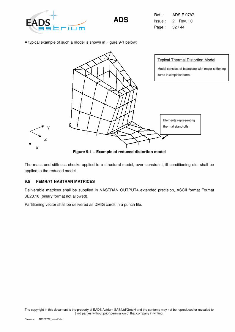
A typical example of such a model is shown in Figure 9-1 below:
Figure 9-1 – Example of reduced distortion model
The mass and stiffness checks applied to a structural model, over–constraint, ill conditioning etc. shall be
applied to the reduced model.
9.5 FEMR/71 NASTRAN MATRICES
Deliverable matrices shall be supplied in NASTRAN OUTPUT4 extended precision, ASCII format Format
3E23.16 (binary format not allowed).
Partitioning vector shall be delivered as DMIG cards in a punch file.
Y
Z
X
Typical Thermal Distortion Model
Model consists of baseplate with major stiffening
items in simplified form.
Elements representing
thermal stand-offs.
ADS
Ref. :
Issue :
Page :
ADS.E.0787
2 Rev. : 0
33 / 44
The copyright in this document is the property of EADS Astrium SAS/Ltd/GmbH and the contents may not be reproduced or revealed to third parties without prior permission of that company in writing.
Filename ADSE0787_issue2.doc
10 GENERAL PRACTICES
10.1 FREE BOUNDARIES
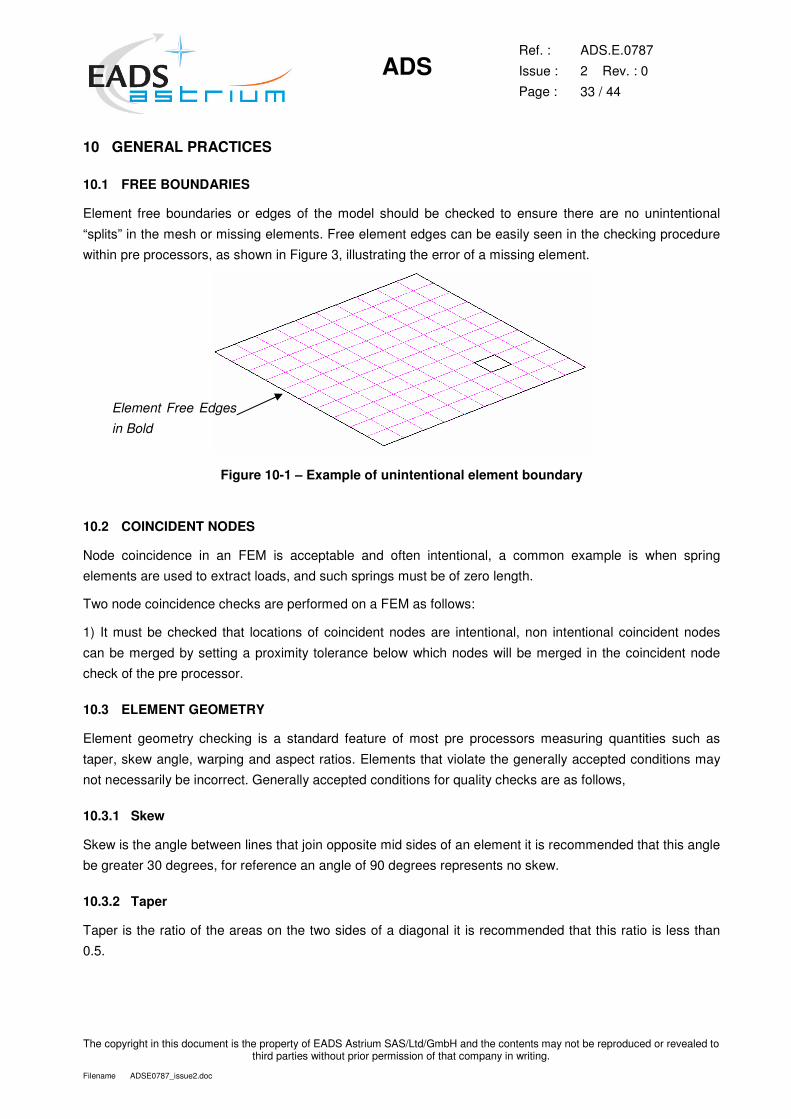
Element free boundaries or edges of the model should be checked to ensure there are no unintentional
“splits” in the mesh or missing elements. Free element edges can be easily seen in the checking procedure
within pre processors, as shown in Figure 3, illustrating the error of a missing element.
Figure 10-1 – Example of unintentional element boundary
10.2 COINCIDENT NODES
Node coincidence in an FEM is acceptable and often intentional, a common example is when spring
elements are used to extract loads, and such springs must be of zero length.
Two node coincidence checks are performed on a FEM as follows:
1) It must be checked that locations of coincident nodes are intentional, non intentional coincident nodes
can be merged by setting a proximity tolerance below which nodes will be merged in the coincident node
check of the pre processor.
10.3 ELEMENT GEOMETRY
Element geometry checking is a standard feature of most pre processors measuring quantities such as
taper, skew angle, warping and aspect ratios. Elements that violate the generally accepted conditions may
not necessarily be incorrect. Generally accepted conditions for quality checks are as follows,
10.3.1 Skew
Skew is the angle between lines that join opposite mid sides of an element it is recommended that this angle
be greater 30 degrees, for reference an angle of 90 degrees represents no skew.
10.3.2 Taper
Taper is the ratio of the areas on the two sides of a diagonal it is recommended that this ratio is less than
0.5.
Element Free Edges
in Bold
ADS
Ref. :
Issue :
Page :
ADS.E.0787
2 Rev. : 0
34 / 44
The copyright in this document is the property of EADS Astrium SAS/Ltd/GmbH and the contents may not be reproduced or revealed to third parties without prior permission of that company in writing.
Filename ADSE0787_issue2.doc
10.3.3 Aspect ratio
Aspect ratio is the ratio of the length of any two sides on a CQUAD4 element. It is recommended that this
value is less than 4.
10.3.4 Warp
Warping of shell elements occur when the connected grids are not in the same plane. The warping value is
determined from the distance of the corner from the mid plane of the grids and the sum of the diagonals.
When the warping value exceeds the defined tolerance a warning message is provided.
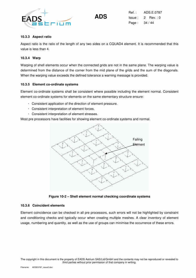
10.3.5 Element co-ordinate systems
Element co-ordinate systems shall be consistent where possible including the element normal. Consistent
element co-ordinate systems for elements on the same elementary structure ensure:
� Consistent application of the direction of element pressure.
� Consistent interpretation of element forces.
� Consistent interpretation of element stresses.
Most pre processors have facilities for showing element co-ordinate systems and normal.
Figure 10-2 – Shell element normal checking coordinate systems
10.3.6 Coincident elements
Element coincidence can be checked in all pre processors, such errors will not be highlighted by constraint
and conditioning checks and typically occur when creating multiple meshes. A clear inventory of element
usage, numbering and quantity, as well as the use of groups can minimise the occurrence of these errors.
Failing
Element
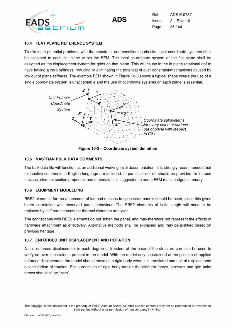
ADS
Ref. :
Issue :
Page :
ADS.E.0787
2 Rev. : 0
35 / 44
The copyright in this document is the property of EADS Astrium SAS/Ltd/GmbH and the contents may not be reproduced or revealed to third parties without prior permission of that company in writing.
Filename ADSE0787_issue2.doc
10.4 FLAT PLANE REFERENCE SYSTEM
To eliminate potential problems with the constraint and conditioning checks, local coordinate systems shall
be assigned to each flat plane within the FEM. The local co-ordinate system of the flat plane shall be
assigned as the displacement system for grids on that plane. This will cause in the in plane rotational dof to
have having a zero stiffness, reducing or eliminating the potential of over constraint/mechanisms caused by
low out of plane stiffness. The example FEM shown in Figure 10-3 shows a typical shape where the use of a
single coordinate system is unacceptable and the use of coordinate systems on each plane is essential.
�
X
Y Z
X’’
Z’’
Y’’
X’ Z’
Unit Primary
Coordinate System
CS1 Coordinate subsystems for every plane or surface out of plane with respect to CS1
Y
Figure 10-3 – Coordinate system definition
10.5 NASTRAN BULK DATA COMMENTS
The bulk data file will function as an additional working level documentation. It is strongly recommended that
exhaustive comments in English language are included. In particular details should be provided for lumped
masses, element section properties and materials. It is suggested to add a FEM mass budget summary.
10.6 EQUIPMENT MODELLING
RBE2 elements for the attachment of lumped masses to spacecraft panels should be used, since this gives
better correlation with observed panel behaviour. The RBE2 elements of finite length will need to be
replaced by stiff bar elements for thermal distortion analyses.
The connections with RBE3 elements do not stiffen the panel, and may therefore not represent the effects of
hardware attachment as effectively. Alternative methods shall be explained and may be justified based on
previous heritage.
10.7 ENFORCED UNIT DISPLACEMENT AND ROTATION
A unit enforced displacement in each degree of freedom at the base of the structure can also be used to
verify no over constraint is present in the model. With the model only constrained at the position of applied
enforced displacement the model should move as a rigid body when it is translated one unit of displacement
or one radian of rotation. For a condition of rigid body motion the element forces, stresses and grid point
forces should all be “zero”.
ADS
Ref. :
Issue :
Page :
ADS.E.0787
2 Rev. : 0
36 / 44
The copyright in this document is the property of EADS Astrium SAS/Ltd/GmbH and the contents may not be reproduced or revealed to third parties without prior permission of that company in writing.
Filename ADSE0787_issue2.doc
Ideally with the enforced displacement applied at the centre of gravity and displacements reported in the
basic co-ordinate system the displacement results from the three translational subcases should be 1.0 in the
input direction and zero in the other five directions. For the rotational cases the rotation in the input direction
should be 1.0 and 0.0 in the two rotational directions. The translations from the rotational cases will not be
zero.
This check is suited to the reporting of grid point displacements transformed to the basic co-ordinate system.
10.8 DIAGONAL TERMS OF STIFFNESS MATRIX
Warning messages associated with inconsistent material properties should be investigated. The material
properties are used to compute the stiffness properties associated with the degrees of freedom of the
element. NASTRAN for example uses only Young’s Modulus for axial and bending stiffness and shear
modulus for the torsional stiffness of linear elements; Poisson’s Ratio is not used. For shell elements
Young’s Modulus and Poisson’s Ratio is used for in plane stiffness properties and shear modulus only for
transverse shear.
Printing the diagonal items of the stiffness matrix may be useful to assess the potential ill conditioning of
inconsistent material properties.
10.9 DFLR CHECK
The NASTRAN procedure for this conditioning check is based on this method of determining the existence
of singularities. The F-set size stiffness matrix is partitioned by use of a SUPORT card as follows:
��
���
�=
�����
�������
��
It is the sub-matrix KFRFR which is decomposed and so any singularities in this matrix are associated with
‘soft’ areas within the structure. The degrees of freedom chosen for the R-set by entering them on the
SUPORT card should be those which most closely represent the true support conditions of the structure.
However only six degrees of freedom should be used in order to give a statically determinate support.
There are two matrices to be studied as a result of this check designated DLFR and MECHFR (equivalent to
MAXRATIO). Firstly the matrix DLFR outputs the diagonal terms of the decomposed stiffness matrix if they
are less than unity, as a small value indicates a point of low stiffness. Secondly the matrix MECHFR outputs
the ratio between the terms on the leading diagonal of the matrix KFRFR to those on the leading diagonal of
the decomposed stiffness matrix, if the value exceeds 1000. The DOFs identified by MECHFR indicate the
presence of potential mechanisms in the structure.
The expected accuracy to be achieved from this check is as follows
DLFR Values : > 1.0E-3 and> 0.0
10.10 WARNING MESSAGES
Any warning messages occurring in the NASTRAN f06 file shall be reviewed to confirm they do not influence
the results obtained.

ADS
Ref. :
Issue :
Page :
ADS.E.0787
2 Rev. : 0
37 / 44
The copyright in this document is the property of EADS Astrium SAS/Ltd/GmbH and the contents may not be reproduced or revealed to third parties without prior permission of that company in writing.
Filename ADSE0787_issue2.doc
10.11 MAGNITUDE OF SPCFORCE AT GRIDS CONSTRAINED BY AUTOSPC.
Forces associated with degrees freedom constrained by AUTOSPC should tend to zero. In practice some
non-zero constraint forces will exist the magnitude however should be reduced to a quantity that produces
negligible errors both to the overall solution and to the model locally.
10.12 VERIFICATION OF APPLIED DYNAMIC LOAD
To confirm correct magnitude and frequency distribution of load has been applied a graph of the applied
dynamic load, sine, random or transient in each direction shall be obtained.
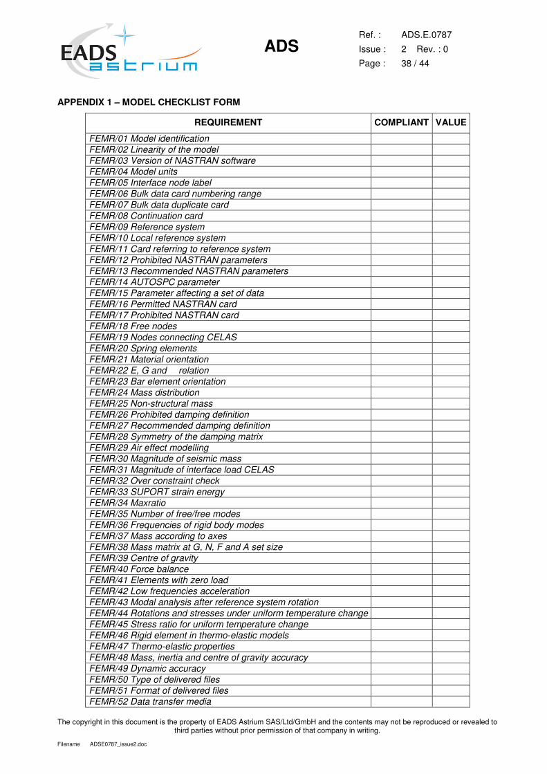
ADS
Ref. :
Issue :
Page :
ADS.E.0787
2 Rev. : 0
38 / 44
The copyright in this document is the property of EADS Astrium SAS/Ltd/GmbH and the contents may not be reproduced or revealed to third parties without prior permission of that company in writing.
Filename ADSE0787_issue2.doc
APPENDIX 1 – MODEL CHECKLIST FORM
REQUIREMENT COMPLIANT VALUE
FEMR/01 Model identification FEMR/02 Linearity of the model FEMR/03 Version of NASTRAN software FEMR/04 Model units FEMR/05 Interface node label FEMR/06 Bulk data card numbering range FEMR/07 Bulk data duplicate card FEMR/08 Continuation card FEMR/09 Reference system FEMR/10 Local reference system FEMR/11 Card referring to reference system FEMR/12 Prohibited NASTRAN parameters FEMR/13 Recommended NASTRAN parameters FEMR/14 AUTOSPC parameter FEMR/15 Parameter affecting a set of data FEMR/16 Permitted NASTRAN card FEMR/17 Prohibited NASTRAN card FEMR/18 Free nodes FEMR/19 Nodes connecting CELAS FEMR/20 Spring elements FEMR/21 Material orientation FEMR/22 E, G and � relation FEMR/23 Bar element orientation FEMR/24 Mass distribution FEMR/25 Non-structural mass FEMR/26 Prohibited damping definition FEMR/27 Recommended damping definition FEMR/28 Symmetry of the damping matrix FEMR/29 Air effect modelling FEMR/30 Magnitude of seismic mass FEMR/31 Magnitude of interface load CELAS FEMR/32 Over constraint check FEMR/33 SUPORT strain energy FEMR/34 Maxratio FEMR/35 Number of free/free modes FEMR/36 Frequencies of rigid body modes FEMR/37 Mass according to axes FEMR/38 Mass matrix at G, N, F and A set size FEMR/39 Centre of gravity FEMR/40 Force balance FEMR/41 Elements with zero load FEMR/42 Low frequencies acceleration FEMR/43 Modal analysis after reference system rotation FEMR/44 Rotations and stresses under uniform temperature change FEMR/45 Stress ratio for uniform temperature change FEMR/46 Rigid element in thermo-elastic models FEMR/47 Thermo-elastic properties FEMR/48 Mass, inertia and centre of gravity accuracy FEMR/49 Dynamic accuracy FEMR/50 Type of delivered files FEMR/51 Format of delivered files FEMR/52 Data transfer media
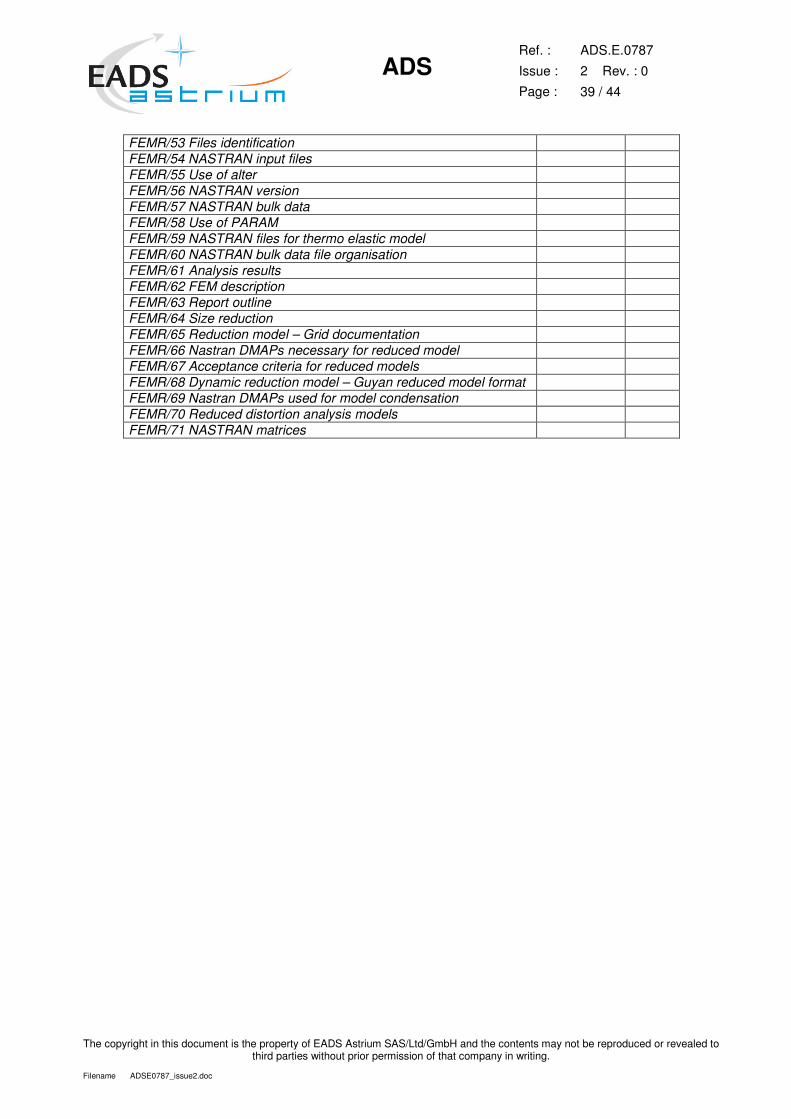
ADS
Ref. :
Issue :
Page :
ADS.E.0787
2 Rev. : 0
39 / 44
The copyright in this document is the property of EADS Astrium SAS/Ltd/GmbH and the contents may not be reproduced or revealed to third parties without prior permission of that company in writing.
Filename ADSE0787_issue2.doc
FEMR/53 Files identification FEMR/54 NASTRAN input files FEMR/55 Use of alter FEMR/56 NASTRAN version FEMR/57 NASTRAN bulk data FEMR/58 Use of PARAM FEMR/59 NASTRAN files for thermo elastic model FEMR/60 NASTRAN bulk data file organisation FEMR/61 Analysis results FEMR/62 FEM description FEMR/63 Report outline FEMR/64 Size reduction FEMR/65 Reduction model – Grid documentation FEMR/66 Nastran DMAPs necessary for reduced model FEMR/67 Acceptance criteria for reduced models FEMR/68 Dynamic reduction model – Guyan reduced model format FEMR/69 Nastran DMAPs used for model condensation FEMR/70 Reduced distortion analysis models FEMR/71 NASTRAN matrices
ADS
Ref. :
Issue :
Page :
ADS.E.0787
2 Rev. : 0
40 / 44
The copyright in this document is the property of EADS Astrium SAS/Ltd/GmbH and the contents may not be reproduced or revealed to third parties without prior permission of that company in writing.
Filename ADSE0787_issue2.doc
APPENDIX 2 – STRUCTURAL MODEL REDUCTION THEORY AND PROCEDURE
REDUCED MODELS
This section details the reduction methods and the delivery formats required for mathematical models to be
used for dynamic analyses.
REASONS FOR REDUCTION
System level mathematical models must be limited in size such that dynamic analyses are not uneconomic
or impractical.
Delivered finite element models shall be those, which are used for detail analysis and design. They shall be
mathematically reduced in one of the manners described in this section as appropriate.
SELECTION CRITERIA FOR REDUCTION METHOD
The format of the delivered reduced model depends upon the number of degrees of freedom required to
adequately define the dynamic behaviour of the sub-system. The frequency range needed is [0-140 Hz]
when rigidly mounted at its interface, or a larger range till the sum of participating masses reached 95% of
the rigid mass.
The dynamic behaviour will be deemed adequate when it can be shown that the criteria outlined in Section 5
is met. If it is proven that the reduced model meets the above criteria by statically condensing the full model
(Guyan Reduction) using 350 DOF, then it may be delivered as a physical model as detailed in Section 4.1,
otherwise the model must be reduced using the modal model approach detailed in below.
Any major discrepancies in the dynamic behaviour between the reduced and unreduced model must be fully
justified.
STATIC REDUCED MODEL (GUYAN CONDENSATION)
An analysis set (A-set) is defined for the instrument or appendage, which contains the degrees of freedom
necessary to represent its dynamic behaviour. In addition the A-set must contain all interface degrees of
freedom, which are used to integrate the instrument or appendage into the system model (six degrees of
freedom per interface point).
A dynamic analysis of the instrument or appendage in its Free-Free state is then performed using the A-set
and the resulting reduced mass and stiffness matrices, sorted into external sort order (MAAEXT &
KAAEXT).
The damping shall be provided as a table of modal damping values in terms of viscous damping ratio,
versus frequency.
DYNAMIC REDUCED MODEL (MODAL SYNTHESIS)
For mathematical models with a large number of modes below 140 Hz, which cannot be represented by the
Guyan approach, the following modal approach must be adopted.
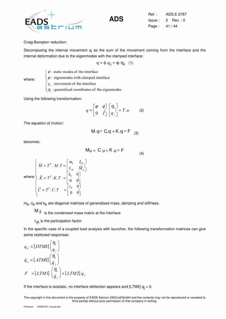
ADS
Ref. :
Issue :
Page :
ADS.E.0787
2 Rev. : 0
41 / 44
The copyright in this document is the property of EADS Astrium SAS/Ltd/GmbH and the contents may not be reproduced or revealed to third parties without prior permission of that company in writing.
Filename ADSE0787_issue2.doc
Craig-Bampton reduction:
Decomposing the internal movement qi as the sum of the movement coming from the interface and the
internal deformation due to the eigenmodes with the clamped interface:
� � � �= +φ ϕ η� � (1)
where:
φϕ
η
�
�
�
�
����� ��� �����������
����� ��� ��������� �������
� ������ �����������
��������� � ������ ��������� ���
�
�
�
�
Using the following transformation:
�
��
�
=�
��
�
���
��
�
�� =
ϕ φ η�
� (2)
The equation of motion:
(3)
becomes:
(4)
where:
�� � �
�� �
�� �
� � � �
� �
�
� � �
� ��
�� ��
�
�
= =�
��
�
��
= =�
��
�
��
= =�
��
�
��
�
�
�
� �
�
� �
mk, ck and kk are diagonal matrices of generalised mass, damping and stiffness.
is the condensed mass matrix at the interface
Ljk is the participation factor.
In the specific case of a coupled load analysis with launcher, the following transformation matrices can give
some restituted responses:
[ ]
[ ]
[ ] [ ]
� ��
� ��
� � �
� �
�
�
�
�
�
�
�
��
=�
�
�
��
=�
�
�
��
=�
�
�
�� +
η
η
η
��
��
��
��
��� �
If the interface is isostatic, no interface deflection appears and [LTM2] qj = 0.
M u u K u F + + = C
M q C q K q F . . . = + +
jj M

ADS
Ref. :
Issue :
Page :
ADS.E.0787
2 Rev. : 0
42 / 44
The copyright in this document is the property of EADS Astrium SAS/Ltd/GmbH and the contents may not be reproduced or revealed to third parties without prior permission of that company in writing.
Filename ADSE0787_issue2.doc
The matrices contain the result of the condensation on the 6 d.o.f of all the interface points, plus SPOINT
defining the « q » generalised co-ordinates corresponding to the first modes of the structure (till 140 Hz).
For restitution purposes, specific interior grid points can be added in the delivered matrices (by means of
Nastran C-set for example).
FEATURES FOR DEPLOYED REDUCED DYNAMIC MICRO-VIBRATION MODELS
Reduced deployed dynamic models will be used to determine the high frequency behaviour of the
spacecraft when in-orbit. It will be enable the effect of an instrument disturbance in combination with the
satellite’s flexible behaviour to be evaluated in order to assess the impacts on sensitive equipment
elsewhere on the satellite.
In order to be able to perform a meaningful analysis, it is necessary that the instrument models employed
include some specific degrees of freedom added, as follows:
(a) Input Points - Nodes corresponding to the application points of the disturbance
Example: If a motor is generating the disturbance then the model will require nodes corresponding to the
stator and rotor of the motor. The rotations or torque being applied at these points are necessary in order to
perform the micro-vibration analyses.
The nodes supplied for inputs must contain the relevant stiffness in each DOF, and must be connected to
the remainder of the model in a representative manner.
(b) Output Points - Nodes corresponding to the sensitive parts of the instrument
Example: The line of sight of an instrument, which may be a virtual point obtained by linear combinations of
other degrees of freedom. The micro-vibration budget will be calculated at these nodes subsequently.
If the instrument manufacturer is interested in knowing the behaviour of one specific interface point, then the
node corresponding to this point is required. Again this node may be virtual node if required.
The associated nomenclature of the nodes is also required.
ACCEPTANCE CRITERIA FOR REDUCED MODELS AND VERIFICATION
The dynamic behaviour of the model will at some stage be verified by carrying out a modal survey or a
program of sine and/or random vibration testing on representative hardware. The Cross-Orthogonality
Check must demonstrate compliance.
The verification will be demonstrated by performing cross orthogonality checks which should yield values of
more than 0.95 for the diagonal terms and less than 0.10 for off-diagonal terms for all important modes. In
addition major mode frequencies should agree within 3%. Deviations from this will be discussed with the
integrator with a view to obtaining concurrence.
Models delivered subsequent to modal survey testing must adopt the changes used to obtain correlation.
- Thermoelastic behaviour:
The displacements on optical components and interface forces shall not differ by more than 5% when the
structure is submitted to a uniform temperature increase. For this calculation, the structure is fixed using the
interface conditions specified for dynamic analysis.
ADS
Ref. :
Issue :
Page :
ADS.E.0787
2 Rev. : 0
43 / 44
The copyright in this document is the property of EADS Astrium SAS/Ltd/GmbH and the contents may not be reproduced or revealed to third parties without prior permission of that company in writing.
Filename ADSE0787_issue2.doc
DELIVERY FORMAT FOR REDUCED MODELS
Two types of deliveries for condensed models are possible:
- mass and stiffness matrices generated by the module OUTPUT4 of NASTRAN, with the format E23.16,
with a partitioning vector with the format DMIG (Each degree of freedom kept in the matrices has a unit
value in this vector). The mass and stiffness matrices must have the same size. The order of the degrees of
freedom in the matrices is the external order.
- mass and stiffness matrices generated with the format DMIG. The values can only be delivered with a
format E16.9 which is not always sufficient to satisfy the verification requirements.
The bulk file corresponding to the here-above matrices must contain:
- the necessary co-ordinate systems - the Grids and Spoints associated with the matrices - PLOTEL elements connecting the delivered grids in order to visualise the structure and the mode shapes.
REDUCED THERMO-ELASTIC / ALIGNMENT MODELS
These models are simplified static models which are derived from the full static model.
The purpose of producing this reduced model is to minimise the effort required by the instrument supplier in
detailing the thermal properties of all components in the full static model, and to reduce the size of model
used for determining the thermo-elastic behaviour at system level.
Two matrices shall be provided, corresponding to the static condensation (Guyan reduction) on the interface
degrees of freedom (6 per I/f) and the restitution nodes.
� the stiffness matrix
� the load vector corresponding to interface forces for a unitary temperature increase with clamped
boundary conditions
Note: the sum of all interface forces for a unitary temperature increase shall be zero
ADS
Ref. :
Issue :
Page :
ADS.E.0787
2 Rev. : 0
44 / 44
The copyright in this document is the property of EADS Astrium SAS/Ltd/GmbH and the contents may not be reproduced or revealed to third parties without prior permission of that company in writing.
Filename ADSE0787_issue2.doc
CHANGE RECORD
ISSUE DATE CHANGE
1.0 06.02.06 Initial Issue
2.0 15.11.07 Selected requirements Revised to suit upgrade MSC MD NASTRAN Version
v2006r1:
FEMR/03, FEMR/12, FEMR/13, FEMR/17, FEMR/46
Reference to MSC NASTRAN V2005 replaced by MSC MD NASTRAN v2006r1