Embed Size (px)
Citation preview

Generator Sizing Guide

2
IMPORTANT NOTICE: This booklet is designed to familiarize estimators and installers with proper sizing guidelines for residential and commercial generators. The information is not comprehensive, nor does it replace or supercede any material contained in any of the written documents shipped with the equipment. This booklet should only be used in conjunction with the Owner’s Manual, Installation Manual and other technical documents shipped with each product. Always read all accompanying documentation carefully before attempting to install any generator, transfer switch or related equipment.
HOW TO USE THIS BOOKLET:Within this booklet, you will find electrical load information, plus an outline of generator surge capability, fuel pipe sizing, liquid propane tank sizing, and UPS / generator compatibility. The worksheet pages can be removed from the book and photocopied to create additional Onsite Estimating Sheets for use with individual jobs.
SAFETY INFORMATION:Proper sizing of the generator is crucial to the success of any installation and requires a good working knowledge of electricity and its characteristics, as well as the varying requirements of the electrical equipment comprising the load. When analyzing the electrical load, consult the manufacturer’s nameplate on each major appliance or piece of equipment to determine its starting and running requirements in terms of watts, amps and voltage. When choosing the generator output for commercial or industrial applications, select a rating that is approximately 20 to 25% higher than the peak load (for example, if the load is about 40 kilowatts, select a 50 kW genset). A higher rated generator will operate comfortably at approximately 80% of its full capacity and will provide a margin of flexibility if the load increases in the future.
For safety reasons, Generac recommends that the backup power system be installed, serviced and repaired by a Generac Authorized Service Dealer or a competent, qualified electrician or installation technician who is familiar with applicable codes, standards and regulations.
It is essential to comply with all regulations established by the Occupational Safety & Health Administration (OSHA) and strict adherence to all local, state and national codes is mandatory. Before selecting a generator, check for municipal ordinances that may dictate requirements regarding placement of the unit (setback from building and/or lot line), electrical wiring, gas piping, fuel storage (for liquid propane or diesel tanks), sound and exhaust emissions.

GENERATOR SIZING GUIDE
3
Table of Contents
Placement Diagram - Air-cooled Generators . . . . . . . . . . . . . . . . . . . . . . . . . . . . . . . . . . . . . . . 4
Table 1 – Motor Load Reference . . . . . . . . . . . . . . . . . . . . . . . . . . . . . . . . . . . . . . . . . . . . . . . . 5
Table 2 – Non-Motor Load Reference . . . . . . . . . . . . . . . . . . . . . . . . . . . . . . . . . . . . . . . . . . . . 6
Table 3 – Surge Capability . . . . . . . . . . . . . . . . . . . . . . . . . . . . . . . . . . . . . . . . . . . . . . . . . . . . 7
Table 3A – Protector Series . . . . . . . . . . . . . . . . . . . . . . . . . . . . . . . . . . . . . . . . . . . . . . . . . . . . 8
Natural Gas Installation . . . . . . . . . . . . . . . . . . . . . . . . . . . . . . . . . . . . . . . . . . . . . . . . . . . . . . . 9
Table 4 – Fuel Pipe Sizing – Natural Gas . . . . . . . . . . . . . . . . . . . . . . . . . . . . . . . . . . . . . . . . . . 9
LP Vapor Installation . . . . . . . . . . . . . . . . . . . . . . . . . . . . . . . . . . . . . . . . . . . . . . . . . . . . . . . . 10
Table 5 – Fuel Pipe Sizing – LP Vapor . . . . . . . . . . . . . . . . . . . . . . . . . . . . . . . . . . . . . . . . . . . 10
Table 6 – LP Vapor (LPV) Tank Sizing . . . . . . . . . . . . . . . . . . . . . . . . . . . . . . . . . . . . . . . . . . . . 11
Table 7 –Generator Fuel Consumption . . . . . . . . . . . . . . . . . . . . . . . . . . . . . . . . . . . . . . . . . . 11
UPS – Generator Compatibility . . . . . . . . . . . . . . . . . . . . . . . . . . . . . . . . . . . . . .12
UPS – SIZING EXAMPLES . . . . . . . . . . . . . . . . . . . . . . . . . . . . . . . . . . . . . . . . . .13
Typical Generator/Transfer Switch Combinations . . . . . . . . . . . . . . . . . . . . . . . . . . . . . . . . 14–15
NEC 700, 701, 702 Comparison . . . . . . . . . . . . . . . . . . . . . . . . . . . . . . . . . . . . . . . . . . . . . . . . 16
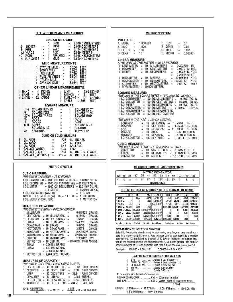
Electrical Formulas, Weights and Measures . . . . . . . . . . . . . . . . . . . . . . . . . . . . . . . . . . . . . . . 18
Tear-out Worksheets: . . . . . . . . . . . . . . . . . . . . . . . . . . . . . . . . . . . . . . . . . . . . . .19
Selected Circuit Load Calculator System Capacity – Load Calculator
3

4
001751
3 ft (0.91 m)
3 ft (0.91 m)
5 ft (1.52 m)5 ft (1.52 m) C
A
B F
ED
3 ft (0.91 m)B B
PLACEMENT DIAGRAM — AIR-COOLED GENERATORS
001789
D
G
ID Description Comments
A Top of generator —
B Front and end clearance Minimum clear distances cannot include shrubs, bushes, or trees.
C Rear clearance 18 in (45.7 cm) minimum clearance per NFPA testing, labeling, and listing, unless state or local codes dictate otherwise.
D Windows and openings No operable windows, doors, or openings in the wall are permitted within 5 ft (1.52 m) from any point of the generator.
E Existing wall One-hour fire rated walls allow closer placement of the generator set without approved enclosure. Confirm before installation.
F Removable fence Removable fence panels for servicing cannot be placed less than 3 ft (0.91 m) in front of the generator.
G Overhead clearance 5 ft (1.52 m) minimum distance from any structure, overhang, or projections from the wall. DO NOT install under wooden decks or structures unless this distance is maintained.

GENERATOR SIZING GUIDE
5
Description Hp Running kWAmps @ 120V 1Ø
4.9Amps @ 240V 1Ø
Starting kWLR Amps @
120V 1ØLR Amps @
240V 1Ø
Refrigerator pump, sump, furnace, garage opener
0.5 0.5 4.9 2.5 1.5 25 13
Freezer, washer, septic grinder 0.75 0.75 7.4 3.7 2.3 38 19
General 1 Hp 1 1 9.8 4.9 3 50 25
Well & septic lift pump 2 2 19.6 9.8 6 100 50
TABLE 1 MOTOR LOAD REFERENCE
Description HpRunning
kWAmps @ 240V 1Ø
Amps @ 208V 3Ø
Amps @ 240V 3Ø
Amps @ 480V 3Ø
LR Amps @ 240V 1Ø
LR Amps @ 208V 3Ø
LR Amps @ 240V 3Ø
LR Amps @ 480V 3Ø
1 Ton (12,000 BTU) 1 1 5 3 3 1 33 22 19 10
2 Ton (24,000 BTU) 2 2 10 7 6 3 67 44 38 19
3 Ton (36,000 BTU) 3 3 15 10 8 4 100 67 58 29
4 Ton (48,000 BTU) 4 4 20 13 11 6 117 78 67 34
5 Ton (60,000 BTU) 5 5 25 16 14 7 145 97 84 42
7.5 Ton (85,000 BTU) 7.5 7.5 37 24 21 11 219 146 126 63
10 Ton* (120,000 BTU)
5 Hp (x2) 10 49 33 28 14 145 97 84 42
10 Ton (120,000 BTU) 10 Hp 10 49 33 28 14 250 167 144 72
15 Ton* (180,000 BTU) 7.5 Hp (x2) 15 74 49 42 21 219 146 126 63
15 Ton (180,000 BTU) 15 Hp 15 74 49 42 21 375 250 217 108
20 Ton* (240,000 BTU)
10 Hp (x2) 20 98 65 57 28 250 167 144 72
20 Ton (240,000 BTU) 20 Hp 20 n/a 65 57 28 500 333 289 144
25 Ton (300,000 BTU) 25 25 n/a 82 71 35 625 416 361 180
30 Ton* (360,000 BTU) 15 Hp (x2) 30 n/a 98 85 42 375 250 217 108
30 Ton (360,000 BTU) 30 Hp 30 n/a 98 85 42 750 500 433 217
40 Ton* (480,000 BTU) 20 Hp (x2) 40 n/a 131 113 57 500 333 289 144
40 Ton (480,000 BTU) 40 Hp 40 n/a 131 113 57 1000 666 577 289
50 Ton* (480,000 BTU) 25 Hp (x2) 50 n/a 163 142 71 625 416 361 180
50 Ton (480,000 BTU) 50 Hp 50 n/a 163 142 71 1250 833 722 361
AC & Heat PumpsRunning Load Starting Load
General Residential
* For Multiple motor configurations, sequence starting is assumed. Air Conditioning1 hp per 1 ton1 ton = 12,000 BTUs
Running Load Starting Load

6
Running Load*
Description kW Amps at120V 1ø Amps at 240V 1øElectric heat per 1000 ft2 12 n/a 50
Heat pump elements per 1000 ft2 7 n/a 29
Dryer 5.5 n/a 23
Hot tub 10 n/a 50
Range oven/Stove top per burner 8 n/a 30
Electric hot water 4.5 n/a 19
General lighting and receptaclesper 1000 ft2 3 24.9 n/a
Blow dryer 1.25 10.4 n/a
Dishwasher 1.5 12.5 n/a
Microwave 1 8.3 n/a
Toasters 1 8.3 n/a
Home Entertainment Center 1 8.3 n/a
Computer 1 8.3 n/a
Kitchen 1.5 12.5 n/a
Laundry 1.5 12.5 n/a
TABLE 2 NON-MOTOR LOAD REFERENCE
Commercial
Please refer to equipment data plate and/or billing history for commercial details.
*Always check data plate for actual running amps.
Residential

GENERATOR SIZING GUIDE
7
Running Load*
Description kW Amps at120V 1ø Amps at 240V 1øElectric heat per 1000 ft2 12 n/a 50
Heat pump elements per 1000 ft2 7 n/a 29
Dryer 5.5 n/a 23
Hot tub 10 n/a 50
Range oven/Stove top per burner 8 n/a 30
Electric hot water 4.5 n/a 19
General lighting and receptaclesper 1000 ft2 3 24.9 n/a
Blow dryer 1.25 10.4 n/a
Dishwasher 1.5 12.5 n/a
Microwave 1 8.3 n/a
Toasters 1 8.3 n/a
Home Entertainment Center 1 8.3 n/a
Computer 1 8.3 n/a
Kitchen 1.5 12.5 n/a
Laundry 1.5 12.5 n/a
Rated Output (Running Amps) LP / NG
Maximum Surge Capability (LR Amps @ 30% Voltage Dip)
Size (kW) RPM 240V 1Ø 208V 3Ø 240V 3Ø 480V 3Ø 240V 1Ø 208V 3Ø 240V 3Ø 480V 3Ø
RG 22 1800 92/92 76/76 66/66 n/a 135 92 80 n/a
RG 25 3600 104/104 87/87 75/75 n/a 170 130 112 n/a
RG 27 1800 113/104 94/87 81/75 n/a 170 120 103 n/a
RG 30 3600 125/125 104/104 90/90 n/a 180 155 134 n/a
RG 32 1800 133/133 111/111 96/96 48/48 180 210 182 87
RG 36 3600 150/146 125/121 108/105 54/53 240 130 115 60
RG 38 1800 158/158 132/132 114/114 57/57 180 210 182 87
RG 45 3600 188/188 156/156 135/135 68/68 240 130 115 60
RG 48 1800 200/200 167/167 144/144 72/72 195 218 189 87
RG 60 3600 250/250 208/208 180/180 90/90 320 210 182 91
QT 70 1800 292/267 242/232 210/201 105/101 356 471 408 201
QT 80 3600 333/333 278/278 240/240 120/120 435 466 404 175
QT 100 2300 417/371 347/326 300/282 150/141 413 452 392 261
QT 130 2970 542/488 451/423 390/367 195/183 648 885 767 390
QT 150 3600 625/625 520/493 451/427 225/214 1214 1334 1156 624
TABLE 3 SURGE CAPABILITY
Temperature Deration:3% for every 10 °C above 25 °C or 1.65% for every 10 °F above 77 °F Altitude Deration (22, 25, 27, 30, 45,48, 70,100,130 & 150): 1% for every 100 m above 183 m or 3% for every 1000 ft above 600 ft Altitude Deration (32,36,38, 60, & 80 kW): 1% for every 100 m above 915 m or 3% for every 1000 ft above 3000 ft
Generac Air-cooled Generators
Generac Liquid-cooled Generators
Rated Output (Running Amps) LP / NG
Maximum Surge Capability (LR Amps @ 30% Voltage Dip)
Size (kW) RPM 240V 1Ø 208V 3Ø 240V 3Ø 480V 3Ø 240V 1Ø 208V 3Ø 240V 3Ø 480V 3Ø
7.5 3600 29/25 n/a n/a n/a 62 n/a n/a n/a
9 3600 33/29 n/a n/a n/a 70 n/a n/a n/a
11 3600 45/42 n/a n/a n/a 92 n/a n/a n/a
15 ECO Varible 63/63 n/a n/a n/a 200 n/a n/a n/a
16 3600 66/66 n/a n/a n/a 130 n/a n/a n/a
20 3600 83/75 n/a n/a n/a 185 n/a n/a n/a
20 SYN Varible 83/75 n/a n/a n/a 200 n/a n/a n/a
22 3600 92/81 n/a n/a n/a 210 n/a n/a n/a
Maximum power decreases about 3.5 percent for each 1,000 feet (304.8 meters) above sea level; and also will decrease about 1 percent for each 6 °C (10 °F) above 16 °C (60 °F)

8
Rated Output (Running Amps) Maximum Surge Capability (LR Amps @ 30% Voltage Dip)
Size (kW) 240V 1 PH 208V 3 PH 240V 3 PH 480V 3 PH 240V 1 PH 208V 3 PH 240V 3 PH 480V 3 PH
15 62 52 45 n/a 129 90 78 n/a
20 83 69 60 n/a 211 143 124 n/a
30 125 104 90 45 168 144 125 64
48/50 200 173 150 75 189 218 189 87
Size (kW) % of Rated Load Gal/Hr L/Hr Total Capacity (Gal/L) Usable Capacity (Gal/L)
15
25% 0.51 1.93
34 Gallons
128.7 Liters
32 Gallons
121.1 Liters
50% 0.79 2.99
75% 1.14 4.31
100% 1.48 5.58
20
25% 0.67 2.6
34 Gallons
128.7 Liters
32 Gallons
121.1 Liters
50% 1.05 3.97
75% 1.52 5.32
100% 1.98 7.48
30
25% 0.92 3.5
62 Gallons
234.7 Liters
57 Gallons
215.8 Liters
50% 1.45 5.5
75% 1.96 7.4
100% 2.74 10.4
48/50
25% 1.35 5.11
62 Gallons
234.7 Liters
57 Gallons
215.8 Liters
50% 2.15 8.14
75% 3.06 11.58
100% 3.98 15.07
Generac Protector Series Generators (diesel)
TABLE 3A SURGE CAPABILITY
Fuel Consumption

GENERATOR SIZING GUIDE
9
Pipe Size (inches)
kW 0.5" 0.75" 1" 1.25" 1.5" 2" 2.5" 3"7-9 10 60 200 75011 30 100 450
15-16 10 35 140 30020-22 10 35 140 300RG 22 10 30 115 250
25 & 30 10 50 200 45027 20 80 175 55032 20 90 175 60036 10 35 80 25038 10 70 150 50045 20 50 175 40048 10 30 75 250 60060 10 30 100 200 70070 10 30 100 200 70080 10 20 75 170 475
100 10 20 75 170 475130 10 40 90 250150 10 30 70 200
Pipe Size (in)kW 0.75" 1" 1.25" 1.5"
7–9 20 60 175
11 30 125 200
15–16 10 60 125
20-22 10 60 125
FUEL PIPE SIZING NATURAL GAS
Note: – Pipe sizing is based on 0.5" H2O pressure drop. – Sizing includes a nominal number of elbows and tees. – Please verify adequate service and meter sizing. – Tables based on black pipe.
TABLE 4 Natural Gas 5" to 7" of Water Column (½" Pressure Drop) (Table values are maximum pipe run in feet.)
TABLE 4B Natural Gas 3.5" to 4.9" of Water Column (Table values are maximum pipe run in feet.)
Natural Gas1 cubic foot = 1,000 BTU1 therm = 100,000 BTUGas consumption = 13,000-16,000 BTU per kW/hr
Pressure1 inch mercury = 13.61 inches water column1 inch Water Column = 0.036 psi3.5–14 inches water column = 0.126 psi to 0.50 psi
Note: Size the fuel pipe to the sizing charts or to local codes. When installing other than Sch. 40 black pipe, please refer to the manufactures sizing charts.The air-cooled generator is not a constant flow appliance, the fuel pipe was sized large enough to supply at least 100% of the generator BTU/hr rating.
5"–7" 7–22 kW5"–14" RG22–60 kW11"–14" 70-150 kW
NATURAL GAS INSTALLATION
FUEL INLET PRESSURE SERIAL NUMBER 1234567LP VAPOR MIN. INLET PRESSURE: 10 In W.C. MAX INLET PRESSURE: 12 In W.C. MAX FLOW RATE: 17 Kw 325000BTY/HR
NATURAL GAS MIN. INLET PRESSURE: 3.5 In W.C. MAX INLET PRESSURE: 7 In W.C. MAX FLOW RATE: 16 Kw 312000BTY/HR

10
TABLE 5 FUEL PIPE SIZING LP VAPOR
LP VAPOR INSTALLATION
Note: – Pipe sizing is based on 0.5" H2O pressure drop. – Sizing includes a nominal number
of elbows and tees. – Please verify adequate service and meter sizing. – Tables based on black pipe.
LP Vapor (LPV) 10" to 12" of Water Column (½" Pressure Drop) (Table values are maximum pipe run in feet.)
LPLPG: 8.55 ft 3/lb., 4.24 lbs./gal., 2500 btu/ft3
LPG: 36.3 ft3 = 1 gal.
Pressure1 inch mercury = 13.61 inches water column1 inch Water Column = 0.036 psi11–14 inches water column = 0.396 psi to 0.50 psi
Note: Size the fuel pipe to the sizing charts or to local codes. When installing other than Sch. 40 black pipe, please refer to the manufactures sizing charts.The air-cooled generator is not a constant flow appliance, the fuel pipe was sized large enough to supply at least 100% of the generator BTU/hr rating.
FUEL INLET PRESSURE SERIAL NUMBER 1234567LP VAPOR MIN. INLET PRESSURE: 10 In W.C. MAX INLET PRESSURE: 12 In W.C. MAX FLOW RATE: 17 Kw 325000BTY/HR
NATURAL GAS MIN. INLET PRESSURE: 3.5 In W.C. MAX INLET PRESSURE: 7 In W.C. MAX FLOW RATE: 16 Kw 312000BTY/HR
Pipe Size (inches)
kW 0.5" 0.75" 1" 1.25" 1.5" 2" 2.5" 3"
7-9 35 175 60011 15 80 350
15-16 40 175 55020-22 20 80 350RG 22 20 100 400
25 & 30 50 200 80027 15 70 300 62532 10 60 280 55036 20 150 325 95038 10 35 200 45045 10 80 200 60048 10 80 200 60060 10 40 100 35070 10 40 100 350 70080 30 80 300 600100 20 60 275 550130 10 30 150 325 800150 10 20 100 250 600

GENERATOR SIZING GUIDE
11
TABLE 6
TABLE 7 GENERATOR FUEL CONSUMPTION
Gas Required for Common AppliancesAPPLIANCE Approximate Input
BTU / Hr
Warm Air FurnaceSingle FamilyMultifamily, per unit
60,000–120,00040,000–60,000
Hydronic Boiler, Space HeatingSingle FamilyMultifamily, per unit
80,000–140,00050,000–80,000
Hydronic Boiler, Space and Water HeatingSingle FamilyMultifamily, per unit
100,000–200,00050,000–100,000
Range, Free Standing, DomesticBuilt-In Oven or Broiler Unit, DomesticBuilt-ln Top Unit, Domestic
50,000–90,00014,000–16,00040,000–85,000
Water Heater, Automatic Storage, 30 to 40 gal. TankWater Heater, Automatic Storage, 50 gal. TankWater Healer, Automatic Storage, Instantaneous
2.5 GPM 3 GPM 4 GPM
Water Heater, Domestic, Circulating or Side-Arm
25,000–50,000
30,000–55,000
115,000–125,000125,000–150,000155,000–200,000
RefrigeratorClothes Dryer, Type 1 (Domestic)Gas Fireplace Direct VentGas logBarbecueGas light
1,500–2,00018,000–22,00020,000–90,00035,000–90,00040,000–80,000
1,400–2,800
LP VAPOR (LPV) TANK SIZINGVapor Withdrawal
Tank Capacity Total (Gal.)
Tank Capacity Useable (Gal.)
Minimum Temp (°F)
Tank Capacity (btu/hr.)
Length (Inches)
Diameter (Inches)
Overall Ht. (Inches)
120 72 40200
246,240164,16082,080
57 24 33
150 90 40200
293,760195,84097,920
68 24 33
250 150 40200
507,600338,400169,200
94 30 39
325 195 40200
642,600428,400214,200
119 30 39
500 300 40200
792,540528,360264,180
119 37 46
850 510 40200
1,217,700811,800405,900
165 41 50
1000 600 40200
1,416,960944,640472,320
192 41 50
Note: Tank BTU capacity and generator run times based upon maintaining a minimum tank fuel level of 20%. Tanks are typically filled to 80% full. Note: Typical fuel consumption based on a generator 100% loaded.
Operating Cost Per Hour
=NG Therms/HR x Cost of NG Therm
Generator kW Rating
Fuel Consumption at 100% BTU/HR
Fuel Consumption at 50% BTU/HR
LP Vapor Nat. Gas LP Vapor Nat. Gas LP Vapor Nat. Gas
BTU/HR GAL/HR BTU/HR BTU/HR GAL/HR BTU/HR
7.5 6 115,000 1.26 117,000 90,000 1 85,000
9 8 125,000 1.37 121,000 79,000 0.87 90,000
11 10 179,000 1.97 159,000 107,000 1.18 111,000
15 ECO 15 ECO 261,000 2.87 281,000 120,000 1.32 134,000
16 16 267,000 2.94 309,000 229,000 2.52 218,000
20 18 324,000 3.56 301,000 216,000 2.52 204,000
20 VSCF 18 VSCF 311,000 3.42 285,000 149,000 1.64 174,000
22 19.5 352,000 3.87 310,000 233,000 2.56 216,000
RG22 22 324,000 3.6 324,000 196,500 2.2 207,000
RG25 25 188,000 2.1 221,000 112,500 1.2 140,000
RG27 25 372,500 4.1 396,000 226,000 2.6 233,000
RG30 30 188,000 2.1 221,000 112,500 1.2 140,000
RG32 32 415,000 4.6 381,000 238,000 2.6 219,000
RG36 36 578,000 6.4 626,000 448,000 5 332,000
RG38 38 480,000 5.3 444,000 270,000 3 260,000
RG45 45 774,000 8.6 836,000 445,000 4.9 501,000
RG48 48 780,000 8.6 638,000 378,000 4.2 425,000
RG60 60 1,000,000 11 1,051,000 580,000 6.4 611,000
QT70 67 1,028,000 11.4 1,020,000 496,000 5.46 500,000
QT80 80 1,163,000 12.8 1,253,000 603,000 6.7 785,000
QT100 94 1,268,000 14 1,260,000 718,000 7.9 713,000
QT130 122 1,798,000 19.8 1,786,000 933,000 10.3 927,000
QT150 142 2,080,000 22.9 2,061,000 1,080,000 11.9 1,070,000

12
Passive (also referenced as standby or off-line) and Line-Interactive
These technologies are most common for personal workstations and point of sale applications. They are typically single phase equipment with size ranges of 350 VA–2000 VA for passive and 500 VA to 5000 VA for line-interactive.
Passive UPS’s are the simplest type. Under normal conditions AC power passes straight through to the UPS load. When the input power supply goes outside of specifications, the UPS transfers the load from input power to the internal DC to AC power inverter. Passive UPS’s do not correct for voltage or frequency deviations under “normal” operation.
Line-interactive is similar to the passive technology except it has circuitry that attempts to correct for standard voltage deviations. Frequency deviations under “normal” power operation are not corrected.
Equipment Notes:These devices tend to be electrically / harmonically very noisy. A single small UPS is not a significant concern, but applications with multiple UPS’s can be problematic.
Passive UPS technology typically has normal tolerances of 10–25% on voltage and 3 hertz on frequency. Minuteman UPS input tolerance is closer to 10–36%. If the input source goes outside of these tolerances, the UPS will switch onto the UPS battery source. Some line-interactive units may have frequency tolerances factory set to 0.5 hertz. These units will need to have their frequency tolerance increased to a minimum of 2 hertz. Minuteman UPS products are close to 5 hertz and not 0.5 hertz.
Generator Sizing Recommendation:Limit the total UPS loading to 15%–20% of the generator capacity.
Double-Conversion (also referenced as on-line)
This technology is most common for critical load applications. Double-conversion UPS’s constantly rectify AC to DC and then invert the DC back into AC. This configuration results in an output that corrects for voltage and frequency deviations.
There are single and three phase models covering small through large applications. Most UPS applications larger than 5000 VA use double conversion technology. This approach is also the preferred technology for generator applications.
Equipment Notes:Double-conversion UPS’s that are single phase or unfiltered three phase models tend to create a significant level of electrical/ harmonic noise. This is illustrated by harmonic current distortions that are greater than 35%. Minuteman UPS products could have current distortion of 8%. When three phase models are supplied with harmonic filters (current distortion less than 10%), this concern is no longer an issue.
Generator Sizing Recommendation:Single phase models: limit the total UPS loading to 25% of the generator capacity. Single phase Minuteman UPS models: limit the total UPS loading to 50% of the generator capacity. Three phase models without filters (current distortion > 30%): limit the UPS loading to 35% of the generator capacity.Three phase models with filters (current distortion < 10%): limit the UPS loading to 80% of the generator capacity.
UPS — GENERATOR COMPATIBILITY
Supplier(s) Passive (Standby) Line-Interactive Double-Conversion
Minuteman UPS Enspire Enterprise Plus Endeavor
APC Back-UPS Series Smart-UPS Series Symmetra Series
Liebert PowerSure PST & PSP PowerSure PSA & PSI UPStation & Nfinity
Powerware 3000 series 5000 series 9000 seriesNote: Ferrups and Delta-Conversion UPS technologies not included in discussion
UPS Information2 x kVA rating for a filtered system3–5 x kVA rating for an unfiltered system

13
GENERATOR SIZING GUIDE
UPS- GENERATOR COMPATIBILITY SIZING EXAMPLES
• UPS systems create electrical or harmonic noise, and this harmonic noise has to be taken into consideration when sizing a generator.
• The generator alternator has to be sized large enough to accept the Total UPS Load from the connected UPS systems.
• Undersizing the generator can cause damage to the UPS equipment, connected equipment, and/or generator.
The sizing formula for UPS systems is the following:Number of Systems X VA Rating X Harmonic Multiplier X Generator Multiplier = Minimum Alternator Size
Single phase generator backing up 3, 2500 VA Line-Interactive UPS Systems with a Harmonic Multiplier of 3
Number of UPS Systems 3
VA Rating 2500
Harmonic Multiplier 3
Total UPS Load 22,500 VA
Generator Multiplier 4
Minimum Generator Alternator Size *90,000 VA
(25% of the generator capacity)
*Note: Depending on any voltage and frequency adjustments with the UPS system, generator range is 80-100 kW 3 Phase generator backing up 4, 10000 VA Double Conversion UPS Systems with a Harmonic Multiplier of 2
Number of UPS Systems 4
VA Rating 10000
Harmonic Multiplier 2
Total UPS Load 80,000 VA
Generator Multiplier 1.25
Minimum Generator Alternator Size 100,000 VA
(80% of the generator capacity)
Sizing Notes: • Always contact the UPS manufacturer when in doubt of the Harmonic Multiplier for the UPS system. • Always use the full VA rating of the UPS system for sizing calculations
• Limit Total UPS loading on single phase generators to 25% of the generators capacity
• Limit Total UPS loading on 3 phase generators to 80% of the generators capacity

14
TYPICAL GENERATOR/TRANSFER SWITCH COMBINATIONSCurrent Model -
EvolutionCurrent Switch
model #Description Prior Models
(5/10-3/13)
Prior Switch Model #(*see note)
Evolution models / transfer switches and prior models / transfer switches listed CAN be used together.
7029
7030
9 kW Air-Cooled Generator - Aluminum6245
6237
RTG10EZA1 10 Circuit Pre-wired Switch RTS10EZA1RTG16EZA3 100 amp 16 Circuit Switch NEMA 3RRTSC100A3 100 amp Normal Smart Switch RTSX100A3
RTSE100A3CSA 100 amp CSA Service Rated Switch RTSE100A3CSA
7031
7032
7033
11 kW Air-Cooled Generator - Aluminum
6439
6437
6438
RTG12EZA1 12 Circuit Pre-wired Switch RTS10EZA1RTG16EZA3 100 amp 16 Circuit Switch NEMA 3RRTSC100A3 100 amp Normal Smart Switch RTSX100A3RTSW100A3 100 amp Service Rated Smart Switch RTSR100A3RTSW150A3 150 amp Service Rated Smart Switch RTSR150A3RTSC200A3 200 amp Normal Smart Switch RTSR200A3RTSW200A3 200 amp Service Rated Smart Switch RTSR200A3
5449 GenReady Load Center NEMA 1 54495454 GenReady Load Center NEMA 3R 54545448 Basic GenReady Load Center 5448
RTSE100A3CSA 100 amp CSA Service Rated Switch RTSE100A3CSARTSE200A3CSA 200 amp CSA Service Rated Switch RTSE200A3CSA
703415 kW EcoGen Air-Cooled Generator - Aluminum
6103RTSB200A3 200 amp Service Rated Smart SwitchRTSI200A3 200 amp Normal Smart Switch
7035
7036
7037
16/16 kW Air-Cooled Generator - Aluminum
6459
6461
6462
6721
RTG16EZA1 16 Circuit Pre-wired Switch RTS16E2A1RTG16EZA3 100 amp 16 Circuit Switch NEMA 3RRTSC100A3 100 amp Normal Smart Switch RTSX100A3RTSW100A3 100 amp Service Rated Smart Switch RTSR100A3RTSW150A3 150 amp Service Rated Smart Switch RTSR150A3RTSC200A3 200 amp Normal Smart Switch RTSX200A3RTSW200A3 200 amp Service Rated Smart Switch RTSR200A3
5449 GenReady Load Center NEMA 1 54495454 GenReady Load Center NEMA 3R 54545448 Basic GenReady Load Center 5448
RTSE100A3CSA 100 amp CSA Service Rated Switch RTSE100A3CSARTSE200A3CSA 200 amp CSA Service Rated Switch RTSE200A3CSA
704070241
20 kW Synergy Air-Cooled Generator - Aluminum6055 6089
RTSB200A3 200 amp Service Rated Smart SwitchRTSI200A3 200 amp Normal Smart Switch
7042
7043
22 kW Air-Cooled Generator - Aluminum
6551
6552
RTG16EZA3 100 amp 16 Circuit Switch NEMA 3RRTSC100A3 100 amp Normal Smart Switch RTSX100A3RTSW100A3 100 amp Service Rated Smart Switch RTSR100A3RTSW150A3 150 amp Service Rated Smart Switch RTSR150A3RTSC200A3 200 amp Normal Smart Switch RTSX200A3RTSW200A3 200 amp Service Rated Smart Switch RTSR200A3
5449 GenReady Load Center NEMA 1 54495454 GenReady Load Center NEMA 3R 54545448 Basic GenReady Load Center 5448
RTSE100A3CSA 100 amp CSA Service Rated Switch RTSE100A3CSARTSE200A3CSA 200 amp CSA Service Rated Switch RTSE200A3CSA
7038
7039
20 kW Air-Cooled Generator - Aluminum
6729
6730
RTG16EZA3 100 amp 16 Circuit Switch NEMA 3RRTSC100A3 100 amp Normal Smart Switch RTSX100A3RTSW100A3 100 amp Service Rated Smart Switch RTSR100A3RTSW150A3 150 amp Service Rated Smart Switch RTSR150A3RTSC200A3 200 amp Normal Smart Switch RTSX200A3RTSW200A3 200 amp Service Rated Smart Switch RTSR200A3
5449 GenReady Load Center NEMA 1 54495454 GenReady Load Center NEMA 3R 54545448 Basic GenReady Load Center 5448
RTSE100A3CSA 100 amp CSA Service Rated Switch RTSE100A3CSARTSE200A3CSA 200 amp CSA Service Rated Switch RTSE200A3CSA

15
Current Model - Evolution
Current Switch model #
Description Prior Models (5/10-3/13)
Prior Switch Model #(*see note)
Evolution models / transfer switches and prior models / transfer switches listed CAN be used together.
RG02224ANAXRG02516ANSXRG02724ANAXRG03016ANSX
22 kW Liquid-Cooled Generator, 1phase - Aluminum
QT02224ANANQT02516ANSNQT02724ANANQT03016ANSN
25 kW Liquid-Cooled Generator, 1phase - Steel27 kW Liquid-Cooled Generator, 1phase - Steel30 kW Liquid-Cooled Generator, 1phase - Steel
RTSC100A3 100 amp Normal Smart Switch* RTSX100A3RTSW100A3 100 amp Service Rated Smart Switch* RTSR100A3RTSW150A3 150 amp Service Rated Smart Switch RTSR150A3RTSC200A3 200 amp Normal Smart Switch RTSX200A3RTSW200A3 200 amp Service Rated Smart Switch RTSR200A3
5449 GenReady Load Center NEMA 1 54495454 GenReady Load Center NEMA 3R 54545448 Basic GenReady Load Center 5448
RTSE100A3CSA 100 amp CSA Service Rated Switch RTSE100A3CSARTSE200A3CSA 200 amp CSA Service Rated Switch RTSE200A3CSA
RG03624ANAX
36 kW Liquid-Cooled Generator - Aluminum
QT03624ANAN
RTSC100A3 100 amp Normal Smart Switch* RTSX100A3RTSW100A3 100 amp Service Rated Smart Switch* RTSR100A3RTSW150A3 150 amp Service Rated Smart Switch RTSR150A3RTSC200A3 200 amp Normal Smart Switch RTSX200A3RTSW200A3 200 amp Service Rated Smart Switch RTSR200A3
RTSE100A3CSA 100 amp CSA Service Rated Switch RTSE100A3CSARTSE200A3CSA 200 amp CSA Service Rated Switch RTSE200A3CSA
RG04524ANSX
45 kW Liquid-Cooled Generator - Steel
QT04524ANSNRTSC200A3 200 amp Normal Smart Switch RTSX200A3RTSW200A3 200 amp Service Rated Smart Switch RTSR200A3
RTSE200A3CSA 200 amp CSA Service Rated Switch RTSE200A3CSA
RG04842ANAX
48 kW Liquid-Cooled Generator - Aluminum
QT04842ANAN
RTSC100A3 100 amp Normal Smart Switch* RTSX100A3RTSW100A3 100 amp Service Rated Smart Switch* RSSD100A3RTSC200A3 200 amp Normal Smart Switch RTSX200A3RTSW200A3 200 amp Service Rated Smart Switch RTSR200A3
RTSE100A3CSA 100 amp CSA Service Rated Switch RTSE100A3CSARTSE200A3CSA 200 amp CSA Service Rated Switch RTSE200A3CSA
RTSC400A3 400 amp Normal Smart Switch RTSE200A3CSA
RG06024ANSX**This model available in Steel or Aluminum;
Natural Gas or LP
60 kW Liquid-Cooled Generator -
QT06024ANSN
RTSC100A3 100 amp Normal Smart Switch* RTSX100A3RTSW100A3 100 amp Service Rated Smart Switch* RTSR100A3RTSC200A3 200 amp Normal Smart Switch* RTSX200A3RTSW200A3 200 amp Service Rated Smart Switch* RTSR200A3RTSC400A3 400 amp Normal Smart Switch RTSX400A3
RTS 100–200 amp* 22–48 kW Liquid-Cooled Generator - 3Ø service rated 100–200 amp*RTS 100–400 amp* 22–60 kW Liquid-Cooled Generator - 3Ø options 100–400 amp*RTS 100–800 amp* 70–150 kW Liquid-Cooled Generator - 1 & 3Ø options 100–800 amp*
TYPICAL GENERATOR/TRANSFER SWITCH COMBINATIONS
* See NEC Article 240.21(B)

16
NEC (700, 701, 702) ComparisonArticle 700 - Emergency Article 701 - Standby Article 702 - Optional Standby
Scope Legally required life safetyLegally required critical support
(fire fighting, health hazards, etc)Protect property & facilities
Equipment Approval For Emergency / (UL2200) For Intended Use / (UL2200) For Intended Use / (UL2200) / Not in 2008
Test
ing
Witness Testing (on-sight) At install & periodically At install NonePeriodic Testing Yes Yes NoneBattery Maintenance Yes Yes NoneMaintenance Records Yes Yes NoneLoad Testing Yes Yes None
Capacity All Loads All loads intended to operate at one timeAll loads intended to operate at one time /
Not in 2008Other Standby Loads Allowed Yes with load shedding Yes with load shedding 2008 – Yes with load sheddingPeak Shaving Allowed Yes ?? Yes Yes
Tran
sfer
Sw
itch Automatic Yes Yes No
Equipment Approval For Emergency / (UL1008) For Standby / (UL1008) For Intended Use / (UL1008)Means to Permit Bypass Yes No NoElect. Operated - Mech. Held Yes No NoOther loads No Yes with load shedding N/AMax. Fault Current Capable Yes Yes Yes
Sig
nals
(A
udib
le &
V
isua
l)
Derangement Yes / Standard common alarm Yes / Standard common alarm Yes / Standard common alarmCarrying Load Yes / Displayed at ATS Yes / Displayed at ATS Yes / Displayed at ATSBattery Charger Failed Yes Yes NoGround Fault Indication Yes (480V & 1000A) No NoNFPA 110 Signaling Yes / Optional annunciator Yes / Optional annunciator No
Sig
ns At service Yes / Type & location Yes / Type & location Yes / Type & location
At neutral to ground bonding Yes (if remote) Yes (if remote) Yes (if remote)
Wiring kept independent Yes No NoFire protection (ref 700-9d) Yes (1000 persons or 75' building) No NoMaximum power outage 10 sec 60 sec N/ARetransfer delay 15 min setting 15 min setting NoAutomatic starting Yes Yes NoOn-site fuel requirements 2 hours (see NFPA 110) 2 hours NoneBattery charger Yes Yes NoGround Fault Indication Only No No
TO FIND KNOWN VALUES 1-PHASE 3-PHASE
KILOWATTS (kW) Volts, Current, Power FactorE x I 1000
E x I x 1.73 x PF 1000
KVA Volts, CurrentE x I 1000
E x I x 1.73 1000
AMPERES kW, Volts, Power FactorkW x 1000
EkW x 1000
E x 1.73 x PF
WATTS Volts, Amps, Power Factor Volts x Amps E x I x 1.73 x PF
NO. OF ROTOR POLES Frequency, RPM2 x 60 x Frequency
RPM2 x 60 x frequency
RPM
FREQUENCY RPM, No. of Rotor PolesRPM x Poles
2 x 60RPM x Poles
2 x 60
RPM Frequency, No. of Rotor Poles2 x 60 x Frequency
Rotor Poles2 x 60 x Frequency
Rotor Poles
kW (required for Motor) Motor Horsepower, EfficiencyHP x 0.746 Efficiency
HP x 0.746 Efficiency
RESISTANCE Volts, AmperesE I
E I
VOLTS Ohms, Amperes I x R I x R
AMPERES Ohms, VoltsE R
E R
E = VOLTS I = AMPERES R = RESISTANCE (OHMS) PF = POWER FACTOR
Electrical Formulas
NEC Comparison Table to be used as a general guideline in determining the proper generator for specific applications. Refer to architectural documents for final selection.

GENERATOR SIZING GUIDE
17
Article 700 - Emergency Article 701 - Standby Article 702 - Optional Standby
Scope Legally required life safetyLegally required critical support
(fire fighting, health hazards, etc)Protect property & facilities
Equipment Approval For Emergency / (UL2200) For Intended Use / (UL2200) For Intended Use / (UL2200) / Not in 2008
Test
ing
Witness Testing (on-sight) At install & periodically At install NonePeriodic Testing Yes Yes NoneBattery Maintenance Yes Yes NoneMaintenance Records Yes Yes NoneLoad Testing Yes Yes None
Capacity All Loads All loads intended to operate at one timeAll loads intended to operate at one time /
Not in 2008Other Standby Loads Allowed Yes with load shedding Yes with load shedding 2008 – Yes with load sheddingPeak Shaving Allowed Yes ?? Yes Yes
Tran
sfer
Sw
itch Automatic Yes Yes No
Equipment Approval For Emergency / (UL1008) For Standby / (UL1008) For Intended Use / (UL1008)Means to Permit Bypass Yes No NoElect. Operated - Mech. Held Yes No NoOther loads No Yes with load shedding N/AMax. Fault Current Capable Yes Yes Yes
Sig
nals
(A
udib
le &
V
isua
l)
Derangement Yes / Standard common alarm Yes / Standard common alarm Yes / Standard common alarmCarrying Load Yes / Displayed at ATS Yes / Displayed at ATS Yes / Displayed at ATSBattery Charger Failed Yes Yes NoGround Fault Indication Yes (480V & 1000A) No NoNFPA 110 Signaling Yes / Optional annunciator Yes / Optional annunciator No
Sig
ns At service Yes / Type & location Yes / Type & location Yes / Type & location
At neutral to ground bonding Yes (if remote) Yes (if remote) Yes (if remote)
Wiring kept independent Yes No NoFire protection (ref 700-9d) Yes (1000 persons or 75' building) No NoMaximum power outage 10 sec 60 sec N/ARetransfer delay 15 min setting 15 min setting NoAutomatic starting Yes Yes NoOn-site fuel requirements 2 hours (see NFPA 110) 2 hours NoneBattery charger Yes Yes NoGround Fault Indication Only No No
NOTES
18
19
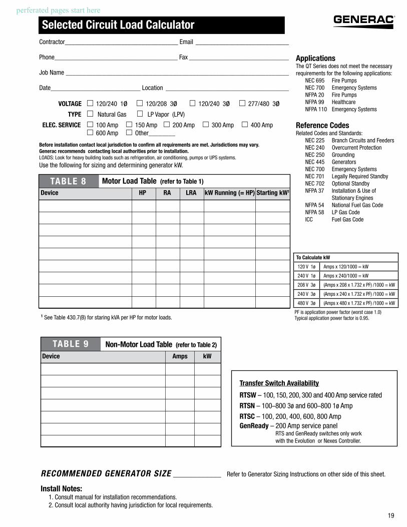
Selected Circuit Load CalculatorContractor__________________________________ Email ____________________________
Phone_____________________________________ Fax ______________________________
Job Name ___________________________________________________________________
Date___________________________ Location _____________________________________
VOLTAGE 120/240 1ø 120/208 3ø 120/240 3ø 277/480 3ø
TYPE Natural Gas LP Vapor (LPV)
ELEC. SERVICE 100 Amp 150 Amp 200 Amp 300 Amp 400 Amp 600 Amp Other________
Before installation contact local jurisdiction to confirm all requirements are met. Jurisdictions may vary. Generac recommends contacting local authorities prior to installation.LOADS: Look for heavy building loads such as refrigeration, air conditioning, pumps or UPS systems.
Use the following for sizing and determining generator kW.
ApplicationsThe QT Series does not meet the necessary requirements for the following applications: NEC 695 Fire Pumps NEC 700 Emergency Systems NFPA 20 Fire Pumps NFPA 99 Healthcare NFPA 110 Emergency Systems
Reference CodesRelated Codes and Standards: NEC 225 Branch Circuits and Feeders NEC 240 Overcurrent Protection NEC 250 Grounding NEC 445 Generators NEC 700 Emergency Systems NEC 701 Legally Required Standby NEC 702 Optional Standby NFPA 37 Installation & Use of Stationary Engines NFPA 54 National Fuel Gas Code NFPA 58 LP Gas Code ICC Fuel Gas Code
1 See Table 430.7(B) for staring kVA per HP for motor loads.
TABLE 9 Non-Motor Load Table (refer to Table 2)
Device Amps kW
RECOMMENDED GENERATOR SIZE ____________ Refer to Generator Sizing Instructions on other side of this sheet.
Install Notes: 1. Consult manual for installation recommendations. 2. Consult local authority having jurisdiction for local requirements.
Transfer Switch Availability
RTSW – 100, 150, 200, 300 and 400 Amp service rated
RTSN – 100–800 3ø and 600–800 1ø Amp
RTSC – 100, 200, 400, 600, 800 AmpGenReady – 200 Amp service panel RTS and GenReady switches only work with the Evolution or Nexes Controller.
TABLE 8 Motor Load Table (refer to Table 1)
Device HP RA LRA kW Running (= HP) Starting kW1
To Calculate kW
120 V 1ø Amps x 120/1000 = kW
240 V 1ø Amps x 240/1000 = kW
208 V 3ø (Amps x 208 x 1.732 x PF) /1000 = kW
240 V 3ø (Amps x 240 x 1.732 x PF) /1000 = kW
480 V 3ø (Amps x 480 x 1.732 x PF) /1000 = kW
PF is application power factor (worst case 1.0) Typical application power factor is 0.95.
perferated pages start here

20
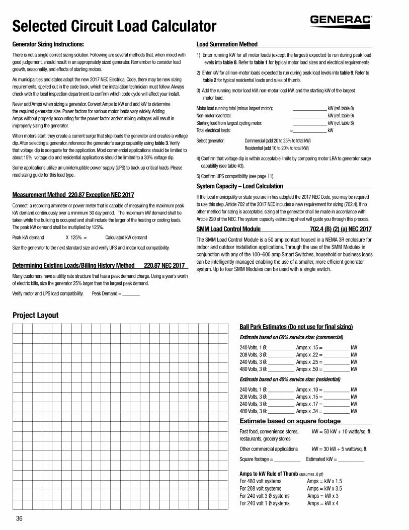
Generator Sizing Instructions:
There is not a single correct sizing solution. Following are several methods that, when mixed with good judgement, should result in an appropriately sized generator. Remember to consider load growth, seasonality, and effects of starting motors.
As municipalities and states adopt the new 2017 NEC Electrical Code, there may be new sizing requirements, spelled out in the code book, which the installation technician must follow. Always check with the local inspection department to confirm which code cycle will affect your install.
Never add Amps when sizing a generator. Convert Amps to kW and add kW to determine the required generator size. Power factors for various motor loads vary widely. Adding Amps without properly accounting for the power factor and/or mixing voltages will result in improperly sizing the generator.
When motors start, they create a current surge that step loads the generator and creates a voltage dip. After selecting a generator, reference the generator's surge capability using table 3. Verify that voltage dip is adequate for the application. Most commercial applications should be limited to about 15% voltage dip and residential applications should be limited to a 30% voltage dip.
Some applications utilize an uninterruptible power supply (UPS) to back up critical loads. Please read sizing guide for this load type.
Measurement Method 220.87 Exception NEC 2017
Connect a recording ammeter or power meter that is capable of measuring the maximum peak kW demand continuously over a minimum 30 day period. The maximum kW demand shall be taken while the building is occupied and shall include the larger of the heating or cooling loads. The peak kW demand shall be multiplied by 125%.
Peak kW demand X 125% = Calculated kW demand
Size the generator to the next standard size and verify UPS and motor load compatibility.
Determining Existing Loads/Billing History Method 220.87 NEC 2017
Many customers have a utility rate structure that has a peak demand charge. Using a year's worth of electric bills, size the generator 25% larger than the largest peak demand.
Verify motor and UPS load compatibility. Peak Demand = _______
Load Summation Method
1) Enter running kW for all motor loads (except the largest) expected to run during peak load levels into table 8. Refer to table 1 for typical motor load sizes and electrical requirements.
2) Enter kW for all non-motor loads expected to run during peak load levels into table 9. Refer to table 2 for typical residential loads and rules of thumb.
3) Add the running motor load kW, non-motor load kW, and the starting kW of the largest motor load.
Motor load running total (minus largest motor): _______________ kW (ref. table 8) Non-motor load total: _______________ kW (ref. table 9) Starting load from largest cycling motor: _______________ kW (ref. table 8) Total electrical loads: =_______________ kW
Select generator: Commercial (add 20 to 25% to total kW) Residential (add 10 to 20% to total kW)
4) Confirm that voltage dip is within acceptable limits by comparing motor LRA to generator surge capability (see table #3).
5) Confirm UPS compatibility (see page 11).
System Capacity – Load Calculation
If the local municipality or state you are in has adopted the 2017 NEC Code, you may be required to use this step. Article 702 of the 2017 NEC includes a new requirement for sizing (702.4). If no other method for sizing is acceptable, sizing of the generator shall be made in accordance with Article 220 of the NEC. The system capacity estimating sheet will guide you through this process.
SMM Load Control Module 702.4 (B) (2) (a) NEC 2017
The SMM Load Control Module is a 50 amp contact housed in a NEMA 3R enclosure for indoor and outdoor installation applications. Through the use of the SMM Modules in conjunction with any of the 100–600 amp Smart Switches, household or business loads can be intelligently managed enabling the use of a smaller, more efficient generator system. Up to four SMM Modules can be used with a single switch.
Selected Circuit Load Calculator
Ball Park Estimates (Do not use for final sizing)
Estimate based on 60% service size: (commercial)
240 Volts, 1 Ø: __________ Amps x .15 = __________ kW 208 Volts, 3 Ø: __________ Amps x .22 = __________ kW 240 Volts, 3 Ø: __________ Amps x .25 = __________ kW 480 Volts, 3 Ø: __________ Amps x .50 = __________ kW
Estimate based on 40% service size: (residential)
240 Volts, 1 Ø: __________ Amps x .10 = __________ kW 208 Volts, 3 Ø: __________ Amps x .15 = __________ kW 240 Volts, 3 Ø: __________ Amps x .17 = __________ kW 480 Volts, 3 Ø: __________ Amps x .34 = __________ kW
Estimate based on square footage
Fast food, convenience stores, kW = 50 kW + 10 watts/sq. ft. restaurants, grocery stores
Other commercial applications kW = 30 kW + 5 watts/sq. ft.
Square footage = __________ Estimated kW = __________
Amps to kW Rule of Thumb (assumes .8 pf)
For 480 volt systems Amps = kW x 1.5For 208 volt systems Amps = kW x 3.5For 240 volt 3 Ø systems Amps = kW x 3For 240 volt 1 Ø systems Amps = kW x 4
Project Layout

21
2013
System Capacity – Load Calculator
DIRECTIONS FOR NEC 2017, ARTICLE 220, PART IV

22
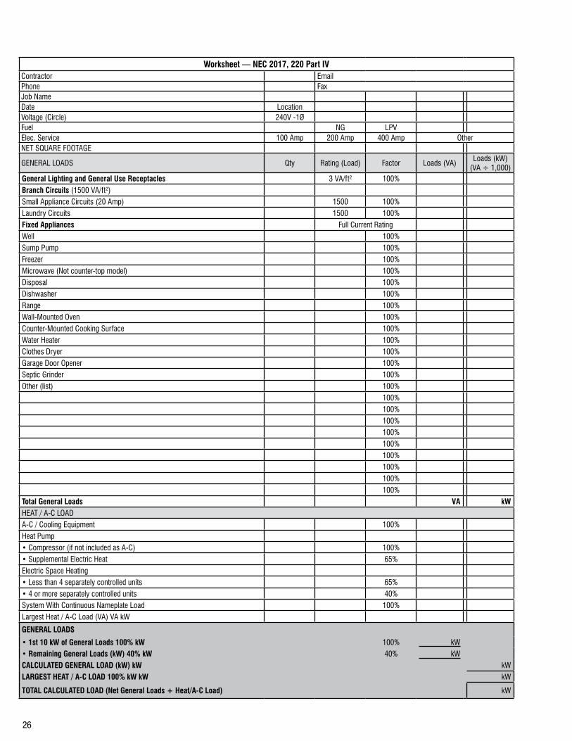
Worksheet — NEC 2017, 220 Part IV Contractor EmailPhone FaxJob NameDate LocationVoltage (Circle) 240V -1ØFuel NG LPVElec. Service 100 Amp 200 Amp 400 Amp OtherNET SQUARE FOOTAGE
GENERAL LOADS Qty Rating (Load) Factor Loads (VA)Loads (kW)
(VA ÷ 1,000)General Lighting and General Use Receptacles 3 VA/ft² 100%Branch Circuits (1500 VA/ft²)Small Appliance Circuits (20 Amp) 1500 100%Laundry Circuits 1500 100%Fixed Appliances Full Current RatingWell 100%Sump Pump 100%Freezer 100%Microwave (Not counter-top model) 100%Disposal 100%Dishwasher 100%Range 100%Wall-Mounted Oven 100%Counter-Mounted Cooking Surface 100%Water Heater 100%Clothes Dryer 100%Garage Door Opener 100%Septic Grinder 100%Other (list) 100%
100%100%100%100%100%100%100%100%100%
Total General Loads VA kWHEAT / A-C LOADA-C / Cooling Equipment 100%Heat Pump• Compressor (if not included as A-C) 100%• Supplemental Electric Heat 65%Electric Space Heating• Less than 4 separately controlled units 65%• 4 or more separately controlled units 40%System With Continuous Nameplate Load 100%Largest Heat / A-C Load (VA) VA kW
GENERAL LOADS
• 1st 10 kW of General Loads 100% kW 100% kW• Remaining General Loads (kW) 40% kW 40% kWCALCULATED GENERAL LOAD (kW) kW kWLARGEST HEAT / A-C LOAD 100% kW kW kW
TOTAL CALCULATED LOAD (Net General Loads + Heat/A-C Load) kW

23
Selected Circuit Load CalculatorContractor__________________________________ Email ____________________________
Phone_____________________________________ Fax ______________________________
Job Name ___________________________________________________________________
Date___________________________ Location _____________________________________
VOLTAGE 120/240 1ø 120/208 3ø 120/240 3ø 277/480 3ø
TYPE Natural Gas LP Vapor (LPV)
ELEC. SERVICE 100 Amp 150 Amp 200 Amp 300 Amp 400 Amp 600 Amp Other________
Before installation contact local jurisdiction to confirm all requirements are met. Jurisdictions may vary. Generac recommends contacting local authorities prior to installation.LOADS: Look for heavy building loads such as refrigeration, air conditioning, pumps or UPS systems.
Use the following for sizing and determining generator kW.
ApplicationsThe QT Series does not meet the necessary requirements for the following applications: NEC 695 Fire Pumps NEC 700 Emergency Systems NFPA 20 Fire Pumps NFPA 99 Healthcare NFPA 110 Emergency Systems
Reference CodesRelated Codes and Standards: NEC 225 Branch Circuits and Feeders NEC 240 Overcurrent Protection NEC 250 Grounding NEC 445 Generators NEC 700 Emergency Systems NEC 701 Legally Required Standby NEC 702 Optional Standby NFPA 37 Installation & Use of Stationary Engines NFPA 54 National Fuel Gas Code NFPA 58 LP Gas Code ICC Fuel Gas Code
1 See Table 430.7(B) for staring kVA per HP for motor loads.
TABLE 9 Non-Motor Load Table (refer to Table 2)
Device Amps kW
RECOMMENDED GENERATOR SIZE ____________ Refer to Generator Sizing Instructions on other side of this sheet.
Install Notes: 1. Consult manual for installation recommendations. 2. Consult local authority having jurisdiction for local requirements.
TABLE 8 Motor Load Table (refer to Table 1)
Device HP RA LRA kW Running (= HP) Starting kW1
To Calculate kW
120 V 1ø Amps x 120/1000 = kW
240 V 1ø Amps x 240/1000 = kW
208 V 3ø (Amps x 208 x 1.732 x PF) /1000 = kW
240 V 3ø (Amps x 240 x 1.732 x PF) /1000 = kW
480 V 3ø (Amps x 480 x 1.732 x PF) /1000 = kW
PF is application power factor (worst case 1.0) Typical application power factor is 0.95.
Transfer Switch Availability
RTSW – 100, 150, 200, 300 and 400 Amp service rated
RTSN – 100–800 3ø and 600–800 1ø Amp
RTSC – 100, 200, 400, 600, 800 AmpGenReady – 200 Amp service panel RTS and GenReady switches only work with the Evolution or Nexes Controller.

24
Generator Sizing Instructions:
There is not a single correct sizing solution. Following are several methods that, when mixed with good judgement, should result in an appropriately sized generator. Remember to consider load growth, seasonality, and effects of starting motors.
As municipalities and states adopt the new 2017 NEC Electrical Code, there may be new sizing requirements, spelled out in the code book, which the installation technician must follow. Always check with the local inspection department to confirm which code cycle will affect your install.
Never add Amps when sizing a generator. Convert Amps to kW and add kW to determine the required generator size. Power factors for various motor loads vary widely. Adding Amps without properly accounting for the power factor and/or mixing voltages will result in improperly sizing the generator.
When motors start, they create a current surge that step loads the generator and creates a voltage dip. After selecting a generator, reference the generator's surge capability using table 3. Verify that voltage dip is adequate for the application. Most commercial applications should be limited to about 15% voltage dip and residential applications should be limited to a 30% voltage dip.
Some applications utilize an uninterruptible power supply (UPS) to back up critical loads. Please read sizing guide for this load type.
Measurement Method 220.87 Exception NEC 2017
Connect a recording ammeter or power meter that is capable of measuring the maximum peak kW demand continuously over a minimum 30 day period. The maximum kW demand shall be taken while the building is occupied and shall include the larger of the heating or cooling loads. The peak kW demand shall be multiplied by 125%.
Peak kW demand X 125% = Calculated kW demand
Size the generator to the next standard size and verify UPS and motor load compatibility.
Determining Existing Loads/Billing History Method 220.87 NEC 2017
Many customers have a utility rate structure that has a peak demand charge. Using a year's worth of electric bills, size the generator 25% larger than the largest peak demand.
Verify motor and UPS load compatibility. Peak Demand = _______
Load Summation Method
1) Enter running kW for all motor loads (except the largest) expected to run during peak load levels into table 8. Refer to table 1 for typical motor load sizes and electrical requirements.
2) Enter kW for all non-motor loads expected to run during peak load levels into table 9. Refer to table 2 for typical residential loads and rules of thumb.
3) Add the running motor load kW, non-motor load kW, and the starting kW of the largest motor load.
Motor load running total (minus largest motor): _______________ kW (ref. table 8) Non-motor load total: _______________ kW (ref. table 9) Starting load from largest cycling motor: _______________ kW (ref. table 8) Total electrical loads: =_______________ kW
Select generator: Commercial (add 20 to 25% to total kW) Residential (add 10 to 20% to total kW)
4) Confirm that voltage dip is within acceptable limits by comparing motor LRA to generator surge capability (see table #3).
5) Confirm UPS compatibility (see page 11).
System Capacity – Load Calculation
If the local municipality or state you are in has adopted the 2017 NEC Code, you may be required to use this step. Article 702 of the 2017 NEC includes a new requirement for sizing (702.4). If no other method for sizing is acceptable, sizing of the generator shall be made in accordance with Article 220 of the NEC. The system capacity estimating sheet will guide you through this process.
SMM Load Control Module 702.4 (B) (2) (a) NEC 2017
The SMM Load Control Module is a 50 amp contact housed in a NEMA 3R enclosure for indoor and outdoor installation applications. Through the use of the SMM Modules in conjunction with any of the 100–600 amp Smart Switches, household or business loads can be intelligently managed enabling the use of a smaller, more efficient generator system. Up to four SMM Modules can be used with a single switch.
Selected Circuit Load Calculator
Ball Park Estimates (Do not use for final sizing)
Estimate based on 60% service size: (commercial)
240 Volts, 1 Ø: __________ Amps x .15 = __________ kW 208 Volts, 3 Ø: __________ Amps x .22 = __________ kW 240 Volts, 3 Ø: __________ Amps x .25 = __________ kW 480 Volts, 3 Ø: __________ Amps x .50 = __________ kW
Estimate based on 40% service size: (residential)
240 Volts, 1 Ø: __________ Amps x .10 = __________ kW 208 Volts, 3 Ø: __________ Amps x .15 = __________ kW 240 Volts, 3 Ø: __________ Amps x .17 = __________ kW 480 Volts, 3 Ø: __________ Amps x .34 = __________ kW
Estimate based on square footage
Fast food, convenience stores, kW = 50 kW + 10 watts/sq. ft. restaurants, grocery stores
Other commercial applications kW = 30 kW + 5 watts/sq. ft.
Square footage = __________ Estimated kW = __________
Amps to kW Rule of Thumb (assumes .8 pf)
For 480 volt systems Amps = kW x 1.5For 208 volt systems Amps = kW x 3.5For 240 volt 3 Ø systems Amps = kW x 3For 240 volt 1 Ø systems Amps = kW x 4
Project Layout

25
2013
System Capacity – Load Calculator
DIRECTIONS FOR NEC 2017, ARTICLE 220, PART IV
26
Worksheet — NEC 2017, 220 Part IV Contractor EmailPhone FaxJob NameDate LocationVoltage (Circle) 240V -1ØFuel NG LPVElec. Service 100 Amp 200 Amp 400 Amp OtherNET SQUARE FOOTAGE
GENERAL LOADS Qty Rating (Load) Factor Loads (VA)Loads (kW)
(VA ÷ 1,000)General Lighting and General Use Receptacles 3 VA/ft² 100%Branch Circuits (1500 VA/ft²)Small Appliance Circuits (20 Amp) 1500 100%Laundry Circuits 1500 100%Fixed Appliances Full Current RatingWell 100%Sump Pump 100%Freezer 100%Microwave (Not counter-top model) 100%Disposal 100%Dishwasher 100%Range 100%Wall-Mounted Oven 100%Counter-Mounted Cooking Surface 100%Water Heater 100%Clothes Dryer 100%Garage Door Opener 100%Septic Grinder 100%Other (list) 100%
100%100%100%100%100%100%100%100%100%
Total General Loads VA kWHEAT / A-C LOADA-C / Cooling Equipment 100%Heat Pump• Compressor (if not included as A-C) 100%• Supplemental Electric Heat 65%Electric Space Heating• Less than 4 separately controlled units 65%• 4 or more separately controlled units 40%System With Continuous Nameplate Load 100%Largest Heat / A-C Load (VA) VA kW
GENERAL LOADS
• 1st 10 kW of General Loads 100% kW 100% kW• Remaining General Loads (kW) 40% kW 40% kWCALCULATED GENERAL LOAD (kW) kW kWLARGEST HEAT / A-C LOAD 100% kW kW kW
TOTAL CALCULATED LOAD (Net General Loads + Heat/A-C Load) kW

27
Selected Circuit Load CalculatorContractor__________________________________ Email ____________________________
Phone_____________________________________ Fax ______________________________
Job Name ___________________________________________________________________
Date___________________________ Location _____________________________________
VOLTAGE 120/240 1ø 120/208 3ø 120/240 3ø 277/480 3ø
TYPE Natural Gas LP Vapor (LPV)
ELEC. SERVICE 100 Amp 150 Amp 200 Amp 300 Amp 400 Amp 600 Amp Other________
Before installation contact local jurisdiction to confirm all requirements are met. Jurisdictions may vary. Generac recommends contacting local authorities prior to installation.LOADS: Look for heavy building loads such as refrigeration, air conditioning, pumps or UPS systems.
Use the following for sizing and determining generator kW.
ApplicationsThe QT Series does not meet the necessary requirements for the following applications: NEC 695 Fire Pumps NEC 700 Emergency Systems NFPA 20 Fire Pumps NFPA 99 Healthcare NFPA 110 Emergency Systems
Reference CodesRelated Codes and Standards: NEC 225 Branch Circuits and Feeders NEC 240 Overcurrent Protection NEC 250 Grounding NEC 445 Generators NEC 700 Emergency Systems NEC 701 Legally Required Standby NEC 702 Optional Standby NFPA 37 Installation & Use of Stationary Engines NFPA 54 National Fuel Gas Code NFPA 58 LP Gas Code ICC Fuel Gas Code
1 See Table 430.7(B) for staring kVA per HP for motor loads.
TABLE 9 Non-Motor Load Table (refer to Table 2)
Device Amps kW
RECOMMENDED GENERATOR SIZE ____________ Refer to Generator Sizing Instructions on other side of this sheet.
Install Notes: 1. Consult manual for installation recommendations. 2. Consult local authority having jurisdiction for local requirements.
TABLE 8 Motor Load Table (refer to Table 1)
Device HP RA LRA kW Running (= HP) Starting kW1
To Calculate kW
120 V 1ø Amps x 120/1000 = kW
240 V 1ø Amps x 240/1000 = kW
208 V 3ø (Amps x 208 x 1.732 x PF) /1000 = kW
240 V 3ø (Amps x 240 x 1.732 x PF) /1000 = kW
480 V 3ø (Amps x 480 x 1.732 x PF) /1000 = kW
PF is application power factor (worst case 1.0) Typical application power factor is 0.95.
Transfer Switch Availability
RTSW – 100, 150, 200, 300 and 400 Amp service rated
RTSN – 100–800 3ø and 600–800 1ø Amp
RTSC – 100, 200, 400, 600, 800 AmpGenReady – 200 Amp service panel RTS and GenReady switches only work with the Evolution or Nexes Controller.

28
Generator Sizing Instructions:
There is not a single correct sizing solution. Following are several methods that, when mixed with good judgement, should result in an appropriately sized generator. Remember to consider load growth, seasonality, and effects of starting motors.
As municipalities and states adopt the new 2017 NEC Electrical Code, there may be new sizing requirements, spelled out in the code book, which the installation technician must follow. Always check with the local inspection department to confirm which code cycle will affect your install.
Never add Amps when sizing a generator. Convert Amps to kW and add kW to determine the required generator size. Power factors for various motor loads vary widely. Adding Amps without properly accounting for the power factor and/or mixing voltages will result in improperly sizing the generator.
When motors start, they create a current surge that step loads the generator and creates a voltage dip. After selecting a generator, reference the generator's surge capability using table 3. Verify that voltage dip is adequate for the application. Most commercial applications should be limited to about 15% voltage dip and residential applications should be limited to a 30% voltage dip.
Some applications utilize an uninterruptible power supply (UPS) to back up critical loads. Please read sizing guide for this load type.
Measurement Method 220.87 Exception NEC 2017
Connect a recording ammeter or power meter that is capable of measuring the maximum peak kW demand continuously over a minimum 30 day period. The maximum kW demand shall be taken while the building is occupied and shall include the larger of the heating or cooling loads. The peak kW demand shall be multiplied by 125%.
Peak kW demand X 125% = Calculated kW demand
Size the generator to the next standard size and verify UPS and motor load compatibility.
Determining Existing Loads/Billing History Method 220.87 NEC 2017
Many customers have a utility rate structure that has a peak demand charge. Using a year's worth of electric bills, size the generator 25% larger than the largest peak demand.
Verify motor and UPS load compatibility. Peak Demand = _______
Load Summation Method
1) Enter running kW for all motor loads (except the largest) expected to run during peak load levels into table 8. Refer to table 1 for typical motor load sizes and electrical requirements.
2) Enter kW for all non-motor loads expected to run during peak load levels into table 9. Refer to table 2 for typical residential loads and rules of thumb.
3) Add the running motor load kW, non-motor load kW, and the starting kW of the largest motor load.
Motor load running total (minus largest motor): _______________ kW (ref. table 8) Non-motor load total: _______________ kW (ref. table 9) Starting load from largest cycling motor: _______________ kW (ref. table 8) Total electrical loads: =_______________ kW
Select generator: Commercial (add 20 to 25% to total kW) Residential (add 10 to 20% to total kW)
4) Confirm that voltage dip is within acceptable limits by comparing motor LRA to generator surge capability (see table #3).
5) Confirm UPS compatibility (see page 11).
System Capacity – Load Calculation
If the local municipality or state you are in has adopted the 2017 NEC Code, you may be required to use this step. Article 702 of the 2017 NEC includes a new requirement for sizing (702.4). If no other method for sizing is acceptable, sizing of the generator shall be made in accordance with Article 220 of the NEC. The system capacity estimating sheet will guide you through this process.
SMM Load Control Module 702.4 (B) (2) (a) NEC 2017
The SMM Load Control Module is a 50 amp contact housed in a NEMA 3R enclosure for indoor and outdoor installation applications. Through the use of the SMM Modules in conjunction with any of the 100–600 amp Smart Switches, household or business loads can be intelligently managed enabling the use of a smaller, more efficient generator system. Up to four SMM Modules can be used with a single switch.
Selected Circuit Load Calculator
Ball Park Estimates (Do not use for final sizing)
Estimate based on 60% service size: (commercial)
240 Volts, 1 Ø: __________ Amps x .15 = __________ kW 208 Volts, 3 Ø: __________ Amps x .22 = __________ kW 240 Volts, 3 Ø: __________ Amps x .25 = __________ kW 480 Volts, 3 Ø: __________ Amps x .50 = __________ kW
Estimate based on 40% service size: (residential)
240 Volts, 1 Ø: __________ Amps x .10 = __________ kW 208 Volts, 3 Ø: __________ Amps x .15 = __________ kW 240 Volts, 3 Ø: __________ Amps x .17 = __________ kW 480 Volts, 3 Ø: __________ Amps x .34 = __________ kW
Estimate based on square footage
Fast food, convenience stores, kW = 50 kW + 10 watts/sq. ft. restaurants, grocery stores
Other commercial applications kW = 30 kW + 5 watts/sq. ft.
Square footage = __________ Estimated kW = __________
Amps to kW Rule of Thumb (assumes .8 pf)
For 480 volt systems Amps = kW x 1.5For 208 volt systems Amps = kW x 3.5For 240 volt 3 Ø systems Amps = kW x 3For 240 volt 1 Ø systems Amps = kW x 4
Project Layout

29
2013
System Capacity – Load Calculator
DIRECTIONS FOR NEC 2017, ARTICLE 220, PART IV

30
Worksheet — NEC 2017, 220 Part IV Contractor EmailPhone FaxJob NameDate LocationVoltage (Circle) 240V -1ØFuel NG LPVElec. Service 100 Amp 200 Amp 400 Amp OtherNET SQUARE FOOTAGE
GENERAL LOADS Qty Rating (Load) Factor Loads (VA)Loads (kW)
(VA ÷ 1,000)General Lighting and General Use Receptacles 3 VA/ft² 100%Branch Circuits (1500 VA/ft²)Small Appliance Circuits (20 Amp) 1500 100%Laundry Circuits 1500 100%Fixed Appliances Full Current RatingWell 100%Sump Pump 100%Freezer 100%Microwave (Not counter-top model) 100%Disposal 100%Dishwasher 100%Range 100%Wall-Mounted Oven 100%Counter-Mounted Cooking Surface 100%Water Heater 100%Clothes Dryer 100%Garage Door Opener 100%Septic Grinder 100%Other (list) 100%
100%100%100%100%100%100%100%100%100%
Total General Loads VA kWHEAT / A-C LOADA-C / Cooling Equipment 100%Heat Pump• Compressor (if not included as A-C) 100%• Supplemental Electric Heat 65%Electric Space Heating• Less than 4 separately controlled units 65%• 4 or more separately controlled units 40%System With Continuous Nameplate Load 100%Largest Heat / A-C Load (VA) VA kW
GENERAL LOADS
• 1st 10 kW of General Loads 100% kW 100% kW• Remaining General Loads (kW) 40% kW 40% kWCALCULATED GENERAL LOAD (kW) kW kWLARGEST HEAT / A-C LOAD 100% kW kW kW
TOTAL CALCULATED LOAD (Net General Loads + Heat/A-C Load) kW

31
Selected Circuit Load CalculatorContractor__________________________________ Email ____________________________
Phone_____________________________________ Fax ______________________________
Job Name ___________________________________________________________________
Date___________________________ Location _____________________________________
VOLTAGE 120/240 1ø 120/208 3ø 120/240 3ø 277/480 3ø
TYPE Natural Gas LP Vapor (LPV)
ELEC. SERVICE 100 Amp 150 Amp 200 Amp 300 Amp 400 Amp 600 Amp Other________
Before installation contact local jurisdiction to confirm all requirements are met. Jurisdictions may vary. Generac recommends contacting local authorities prior to installation.LOADS: Look for heavy building loads such as refrigeration, air conditioning, pumps or UPS systems.
Use the following for sizing and determining generator kW.
ApplicationsThe QT Series does not meet the necessary requirements for the following applications: NEC 695 Fire Pumps NEC 700 Emergency Systems NFPA 20 Fire Pumps NFPA 99 Healthcare NFPA 110 Emergency Systems
Reference CodesRelated Codes and Standards: NEC 225 Branch Circuits and Feeders NEC 240 Overcurrent Protection NEC 250 Grounding NEC 445 Generators NEC 700 Emergency Systems NEC 701 Legally Required Standby NEC 702 Optional Standby NFPA 37 Installation & Use of Stationary Engines NFPA 54 National Fuel Gas Code NFPA 58 LP Gas Code ICC Fuel Gas Code
1 See Table 430.7(B) for staring kVA per HP for motor loads.
TABLE 9 Non-Motor Load Table (refer to Table 2)
Device Amps kW
RECOMMENDED GENERATOR SIZE ____________ Refer to Generator Sizing Instructions on other side of this sheet.
Install Notes: 1. Consult manual for installation recommendations. 2. Consult local authority having jurisdiction for local requirements.
TABLE 8 Motor Load Table (refer to Table 1)
Device HP RA LRA kW Running (= HP) Starting kW1
To Calculate kW
120 V 1ø Amps x 120/1000 = kW
240 V 1ø Amps x 240/1000 = kW
208 V 3ø (Amps x 208 x 1.732 x PF) /1000 = kW
240 V 3ø (Amps x 240 x 1.732 x PF) /1000 = kW
480 V 3ø (Amps x 480 x 1.732 x PF) /1000 = kW
PF is application power factor (worst case 1.0) Typical application power factor is 0.95.
Transfer Switch Availability
RTSW – 100, 150, 200, 300 and 400 Amp service rated
RTSN – 100–800 3ø and 600–800 1ø Amp
RTSC – 100, 200, 400, 600, 800 AmpGenReady – 200 Amp service panel RTS and GenReady switches only work with the Evolution or Nexes Controller.

32
Generator Sizing Instructions:
There is not a single correct sizing solution. Following are several methods that, when mixed with good judgement, should result in an appropriately sized generator. Remember to consider load growth, seasonality, and effects of starting motors.
As municipalities and states adopt the new 2017 NEC Electrical Code, there may be new sizing requirements, spelled out in the code book, which the installation technician must follow. Always check with the local inspection department to confirm which code cycle will affect your install.
Never add Amps when sizing a generator. Convert Amps to kW and add kW to determine the required generator size. Power factors for various motor loads vary widely. Adding Amps without properly accounting for the power factor and/or mixing voltages will result in improperly sizing the generator.
When motors start, they create a current surge that step loads the generator and creates a voltage dip. After selecting a generator, reference the generator's surge capability using table 3. Verify that voltage dip is adequate for the application. Most commercial applications should be limited to about 15% voltage dip and residential applications should be limited to a 30% voltage dip.
Some applications utilize an uninterruptible power supply (UPS) to back up critical loads. Please read sizing guide for this load type.
Measurement Method 220.87 Exception NEC 2017
Connect a recording ammeter or power meter that is capable of measuring the maximum peak kW demand continuously over a minimum 30 day period. The maximum kW demand shall be taken while the building is occupied and shall include the larger of the heating or cooling loads. The peak kW demand shall be multiplied by 125%.
Peak kW demand X 125% = Calculated kW demand
Size the generator to the next standard size and verify UPS and motor load compatibility.
Determining Existing Loads/Billing History Method 220.87 NEC 2017
Many customers have a utility rate structure that has a peak demand charge. Using a year's worth of electric bills, size the generator 25% larger than the largest peak demand.
Verify motor and UPS load compatibility. Peak Demand = _______
Load Summation Method
1) Enter running kW for all motor loads (except the largest) expected to run during peak load levels into table 8. Refer to table 1 for typical motor load sizes and electrical requirements.
2) Enter kW for all non-motor loads expected to run during peak load levels into table 9. Refer to table 2 for typical residential loads and rules of thumb.
3) Add the running motor load kW, non-motor load kW, and the starting kW of the largest motor load.
Motor load running total (minus largest motor): _______________ kW (ref. table 8) Non-motor load total: _______________ kW (ref. table 9) Starting load from largest cycling motor: _______________ kW (ref. table 8) Total electrical loads: =_______________ kW
Select generator: Commercial (add 20 to 25% to total kW) Residential (add 10 to 20% to total kW)
4) Confirm that voltage dip is within acceptable limits by comparing motor LRA to generator surge capability (see table #3).
5) Confirm UPS compatibility (see page 11).
System Capacity – Load Calculation
If the local municipality or state you are in has adopted the 2017 NEC Code, you may be required to use this step. Article 702 of the 2017 NEC includes a new requirement for sizing (702.4). If no other method for sizing is acceptable, sizing of the generator shall be made in accordance with Article 220 of the NEC. The system capacity estimating sheet will guide you through this process.
SMM Load Control Module 702.4 (B) (2) (a) NEC 2017
The SMM Load Control Module is a 50 amp contact housed in a NEMA 3R enclosure for indoor and outdoor installation applications. Through the use of the SMM Modules in conjunction with any of the 100–600 amp Smart Switches, household or business loads can be intelligently managed enabling the use of a smaller, more efficient generator system. Up to four SMM Modules can be used with a single switch.
Selected Circuit Load Calculator
Ball Park Estimates (Do not use for final sizing)
Estimate based on 60% service size: (commercial)
240 Volts, 1 Ø: __________ Amps x .15 = __________ kW 208 Volts, 3 Ø: __________ Amps x .22 = __________ kW 240 Volts, 3 Ø: __________ Amps x .25 = __________ kW 480 Volts, 3 Ø: __________ Amps x .50 = __________ kW
Estimate based on 40% service size: (residential)
240 Volts, 1 Ø: __________ Amps x .10 = __________ kW 208 Volts, 3 Ø: __________ Amps x .15 = __________ kW 240 Volts, 3 Ø: __________ Amps x .17 = __________ kW 480 Volts, 3 Ø: __________ Amps x .34 = __________ kW
Estimate based on square footage
Fast food, convenience stores, kW = 50 kW + 10 watts/sq. ft. restaurants, grocery stores
Other commercial applications kW = 30 kW + 5 watts/sq. ft.
Square footage = __________ Estimated kW = __________
Amps to kW Rule of Thumb (assumes .8 pf)
For 480 volt systems Amps = kW x 1.5For 208 volt systems Amps = kW x 3.5For 240 volt 3 Ø systems Amps = kW x 3For 240 volt 1 Ø systems Amps = kW x 4
Project Layout

33
2013
System Capacity – Load Calculator
DIRECTIONS FOR NEC 2017, ARTICLE 220, PART IV

34
Worksheet — NEC 2017, 220 Part IV Contractor EmailPhone FaxJob NameDate LocationVoltage (Circle) 240V -1ØFuel NG LPVElec. Service 100 Amp 200 Amp 400 Amp OtherNET SQUARE FOOTAGE
GENERAL LOADS Qty Rating (Load) Factor Loads (VA)Loads (kW)
(VA ÷ 1,000)General Lighting and General Use Receptacles 3 VA/ft² 100%Branch Circuits (1500 VA/ft²)Small Appliance Circuits (20 Amp) 1500 100%Laundry Circuits 1500 100%Fixed Appliances Full Current RatingWell 100%Sump Pump 100%Freezer 100%Microwave (Not counter-top model) 100%Disposal 100%Dishwasher 100%Range 100%Wall-Mounted Oven 100%Counter-Mounted Cooking Surface 100%Water Heater 100%Clothes Dryer 100%Garage Door Opener 100%Septic Grinder 100%Other (list) 100%
100%100%100%100%100%100%100%100%100%
Total General Loads VA kWHEAT / A-C LOADA-C / Cooling Equipment 100%Heat Pump• Compressor (if not included as A-C) 100%• Supplemental Electric Heat 65%Electric Space Heating• Less than 4 separately controlled units 65%• 4 or more separately controlled units 40%System With Continuous Nameplate Load 100%Largest Heat / A-C Load (VA) VA kW
GENERAL LOADS
• 1st 10 kW of General Loads 100% kW 100% kW• Remaining General Loads (kW) 40% kW 40% kWCALCULATED GENERAL LOAD (kW) kW kWLARGEST HEAT / A-C LOAD 100% kW kW kW
TOTAL CALCULATED LOAD (Net General Loads + Heat/A-C Load) kW

35
Selected Circuit Load CalculatorContractor__________________________________ Email ____________________________
Phone_____________________________________ Fax ______________________________
Job Name ___________________________________________________________________
Date___________________________ Location _____________________________________
VOLTAGE 120/240 1ø 120/208 3ø 120/240 3ø 277/480 3ø
TYPE Natural Gas LP Vapor (LPV)
ELEC. SERVICE 100 Amp 150 Amp 200 Amp 300 Amp 400 Amp 600 Amp Other________
Before installation contact local jurisdiction to confirm all requirements are met. Jurisdictions may vary. Generac recommends contacting local authorities prior to installation.LOADS: Look for heavy building loads such as refrigeration, air conditioning, pumps or UPS systems.
Use the following for sizing and determining generator kW.
ApplicationsThe QT Series does not meet the necessary requirements for the following applications: NEC 695 Fire Pumps NEC 700 Emergency Systems NFPA 20 Fire Pumps NFPA 99 Healthcare NFPA 110 Emergency Systems
Reference CodesRelated Codes and Standards: NEC 225 Branch Circuits and Feeders NEC 240 Overcurrent Protection NEC 250 Grounding NEC 445 Generators NEC 700 Emergency Systems NEC 701 Legally Required Standby NEC 702 Optional Standby NFPA 37 Installation & Use of Stationary Engines NFPA 54 National Fuel Gas Code NFPA 58 LP Gas Code ICC Fuel Gas Code
1 See Table 430.7(B) for staring kVA per HP for motor loads.
TABLE 9 Non-Motor Load Table (refer to Table 2)
Device Amps kW
RECOMMENDED GENERATOR SIZE ____________ Refer to Generator Sizing Instructions on other side of this sheet.
Install Notes: 1. Consult manual for installation recommendations. 2. Consult local authority having jurisdiction for local requirements.
TABLE 8 Motor Load Table (refer to Table 1)
Device HP RA LRA kW Running (= HP) Starting kW1
To Calculate kW
120 V 1ø Amps x 120/1000 = kW
240 V 1ø Amps x 240/1000 = kW
208 V 3ø (Amps x 208 x 1.732 x PF) /1000 = kW
240 V 3ø (Amps x 240 x 1.732 x PF) /1000 = kW
480 V 3ø (Amps x 480 x 1.732 x PF) /1000 = kW
PF is application power factor (worst case 1.0) Typical application power factor is 0.95.
Transfer Switch Availability
RTSW – 100, 150, 200, 300 and 400 Amp service rated
RTSN – 100–800 3ø and 600–800 1ø Amp
RTSC – 100, 200, 400, 600, 800 AmpGenReady – 200 Amp service panel RTS and GenReady switches only work with the Evolution or Nexes Controller.
36
Generator Sizing Instructions:
There is not a single correct sizing solution. Following are several methods that, when mixed with good judgement, should result in an appropriately sized generator. Remember to consider load growth, seasonality, and effects of starting motors.
As municipalities and states adopt the new 2017 NEC Electrical Code, there may be new sizing requirements, spelled out in the code book, which the installation technician must follow. Always check with the local inspection department to confirm which code cycle will affect your install.
Never add Amps when sizing a generator. Convert Amps to kW and add kW to determine the required generator size. Power factors for various motor loads vary widely. Adding Amps without properly accounting for the power factor and/or mixing voltages will result in improperly sizing the generator.
When motors start, they create a current surge that step loads the generator and creates a voltage dip. After selecting a generator, reference the generator's surge capability using table 3. Verify that voltage dip is adequate for the application. Most commercial applications should be limited to about 15% voltage dip and residential applications should be limited to a 30% voltage dip.
Some applications utilize an uninterruptible power supply (UPS) to back up critical loads. Please read sizing guide for this load type.
Measurement Method 220.87 Exception NEC 2017
Connect a recording ammeter or power meter that is capable of measuring the maximum peak kW demand continuously over a minimum 30 day period. The maximum kW demand shall be taken while the building is occupied and shall include the larger of the heating or cooling loads. The peak kW demand shall be multiplied by 125%.
Peak kW demand X 125% = Calculated kW demand
Size the generator to the next standard size and verify UPS and motor load compatibility.
Determining Existing Loads/Billing History Method 220.87 NEC 2017
Many customers have a utility rate structure that has a peak demand charge. Using a year's worth of electric bills, size the generator 25% larger than the largest peak demand.
Verify motor and UPS load compatibility. Peak Demand = _______
Load Summation Method
1) Enter running kW for all motor loads (except the largest) expected to run during peak load levels into table 8. Refer to table 1 for typical motor load sizes and electrical requirements.
2) Enter kW for all non-motor loads expected to run during peak load levels into table 9. Refer to table 2 for typical residential loads and rules of thumb.
3) Add the running motor load kW, non-motor load kW, and the starting kW of the largest motor load.
Motor load running total (minus largest motor): _______________ kW (ref. table 8) Non-motor load total: _______________ kW (ref. table 9) Starting load from largest cycling motor: _______________ kW (ref. table 8) Total electrical loads: =_______________ kW
Select generator: Commercial (add 20 to 25% to total kW) Residential (add 10 to 20% to total kW)
4) Confirm that voltage dip is within acceptable limits by comparing motor LRA to generator surge capability (see table #3).
5) Confirm UPS compatibility (see page 11).
System Capacity – Load Calculation
If the local municipality or state you are in has adopted the 2017 NEC Code, you may be required to use this step. Article 702 of the 2017 NEC includes a new requirement for sizing (702.4). If no other method for sizing is acceptable, sizing of the generator shall be made in accordance with Article 220 of the NEC. The system capacity estimating sheet will guide you through this process.
SMM Load Control Module 702.4 (B) (2) (a) NEC 2017
The SMM Load Control Module is a 50 amp contact housed in a NEMA 3R enclosure for indoor and outdoor installation applications. Through the use of the SMM Modules in conjunction with any of the 100–600 amp Smart Switches, household or business loads can be intelligently managed enabling the use of a smaller, more efficient generator system. Up to four SMM Modules can be used with a single switch.
Selected Circuit Load Calculator
Ball Park Estimates (Do not use for final sizing)
Estimate based on 60% service size: (commercial)
240 Volts, 1 Ø: __________ Amps x .15 = __________ kW 208 Volts, 3 Ø: __________ Amps x .22 = __________ kW 240 Volts, 3 Ø: __________ Amps x .25 = __________ kW 480 Volts, 3 Ø: __________ Amps x .50 = __________ kW
Estimate based on 40% service size: (residential)
240 Volts, 1 Ø: __________ Amps x .10 = __________ kW 208 Volts, 3 Ø: __________ Amps x .15 = __________ kW 240 Volts, 3 Ø: __________ Amps x .17 = __________ kW 480 Volts, 3 Ø: __________ Amps x .34 = __________ kW
Estimate based on square footage
Fast food, convenience stores, kW = 50 kW + 10 watts/sq. ft. restaurants, grocery stores
Other commercial applications kW = 30 kW + 5 watts/sq. ft.
Square footage = __________ Estimated kW = __________
Amps to kW Rule of Thumb (assumes .8 pf)
For 480 volt systems Amps = kW x 1.5For 208 volt systems Amps = kW x 3.5For 240 volt 3 Ø systems Amps = kW x 3For 240 volt 1 Ø systems Amps = kW x 4
Project Layout

37
2013
System Capacity – Load Calculator
DIRECTIONS FOR NEC 2017, ARTICLE 220, PART IV

38
Worksheet — NEC 2017, 220 Part IV Contractor EmailPhone FaxJob NameDate LocationVoltage (Circle) 240V -1ØFuel NG LPVElec. Service 100 Amp 200 Amp 400 Amp OtherNET SQUARE FOOTAGE
GENERAL LOADS Qty Rating (Load) Factor Loads (VA)Loads (kW)
(VA ÷ 1,000)General Lighting and General Use Receptacles 3 VA/ft² 100%Branch Circuits (1500 VA/ft²)Small Appliance Circuits (20 Amp) 1500 100%Laundry Circuits 1500 100%Fixed Appliances Full Current RatingWell 100%Sump Pump 100%Freezer 100%Microwave (Not counter-top model) 100%Disposal 100%Dishwasher 100%Range 100%Wall-Mounted Oven 100%Counter-Mounted Cooking Surface 100%Water Heater 100%Clothes Dryer 100%Garage Door Opener 100%Septic Grinder 100%Other (list) 100%
100%100%100%100%100%100%100%100%100%
Total General Loads VA kWHEAT / A-C LOADA-C / Cooling Equipment 100%Heat Pump• Compressor (if not included as A-C) 100%• Supplemental Electric Heat 65%Electric Space Heating• Less than 4 separately controlled units 65%• 4 or more separately controlled units 40%System With Continuous Nameplate Load 100%Largest Heat / A-C Load (VA) VA kW
GENERAL LOADS
• 1st 10 kW of General Loads 100% kW 100% kW• Remaining General Loads (kW) 40% kW 40% kWCALCULATED GENERAL LOAD (kW) kW kWLARGEST HEAT / A-C LOAD 100% kW kW kW
TOTAL CALCULATED LOAD (Net General Loads + Heat/A-C Load) kW

39
Selected Circuit Load CalculatorContractor__________________________________ Email ____________________________
Phone_____________________________________ Fax ______________________________
Job Name ___________________________________________________________________
Date___________________________ Location _____________________________________
VOLTAGE 120/240 1ø 120/208 3ø 120/240 3ø 277/480 3ø
TYPE Natural Gas LP Vapor (LPV)
ELEC. SERVICE 100 Amp 150 Amp 200 Amp 300 Amp 400 Amp 600 Amp Other________
Before installation contact local jurisdiction to confirm all requirements are met. Jurisdictions may vary. Generac recommends contacting local authorities prior to installation.LOADS: Look for heavy building loads such as refrigeration, air conditioning, pumps or UPS systems.
Use the following for sizing and determining generator kW.
ApplicationsThe QT Series does not meet the necessary requirements for the following applications: NEC 695 Fire Pumps NEC 700 Emergency Systems NFPA 20 Fire Pumps NFPA 99 Healthcare NFPA 110 Emergency Systems
Reference CodesRelated Codes and Standards: NEC 225 Branch Circuits and Feeders NEC 240 Overcurrent Protection NEC 250 Grounding NEC 445 Generators NEC 700 Emergency Systems NEC 701 Legally Required Standby NEC 702 Optional Standby NFPA 37 Installation & Use of Stationary Engines NFPA 54 National Fuel Gas Code NFPA 58 LP Gas Code ICC Fuel Gas Code
1 See Table 430.7(B) for staring kVA per HP for motor loads.
TABLE 9 Non-Motor Load Table (refer to Table 2)
Device Amps kW
RECOMMENDED GENERATOR SIZE ____________ Refer to Generator Sizing Instructions on other side of this sheet.
Install Notes: 1. Consult manual for installation recommendations. 2. Consult local authority having jurisdiction for local requirements.
TABLE 8 Motor Load Table (refer to Table 1)
Device HP RA LRA kW Running (= HP) Starting kW1
To Calculate kW
120 V 1ø Amps x 120/1000 = kW
240 V 1ø Amps x 240/1000 = kW
208 V 3ø (Amps x 208 x 1.732 x PF) /1000 = kW
240 V 3ø (Amps x 240 x 1.732 x PF) /1000 = kW
480 V 3ø (Amps x 480 x 1.732 x PF) /1000 = kW
PF is application power factor (worst case 1.0) Typical application power factor is 0.95.
Transfer Switch Availability
RTSW – 100, 150, 200, 300 and 400 Amp service rated
RTSN – 100–800 3ø and 600–800 1ø Amp
RTSC – 100, 200, 400, 600, 800 AmpGenReady – 200 Amp service panel RTS and GenReady switches only work with the Evolution or Nexes Controller.

40
Generator Sizing Instructions:
There is not a single correct sizing solution. Following are several methods that, when mixed with good judgement, should result in an appropriately sized generator. Remember to consider load growth, seasonality, and effects of starting motors.
As municipalities and states adopt the new 2017 NEC Electrical Code, there may be new sizing requirements, spelled out in the code book, which the installation technician must follow. Always check with the local inspection department to confirm which code cycle will affect your install.
Never add Amps when sizing a generator. Convert Amps to kW and add kW to determine the required generator size. Power factors for various motor loads vary widely. Adding Amps without properly accounting for the power factor and/or mixing voltages will result in improperly sizing the generator.
When motors start, they create a current surge that step loads the generator and creates a voltage dip. After selecting a generator, reference the generator's surge capability using table 3. Verify that voltage dip is adequate for the application. Most commercial applications should be limited to about 15% voltage dip and residential applications should be limited to a 30% voltage dip.
Some applications utilize an uninterruptible power supply (UPS) to back up critical loads. Please read sizing guide for this load type.
Measurement Method 220.87 Exception NEC 2017
Connect a recording ammeter or power meter that is capable of measuring the maximum peak kW demand continuously over a minimum 30 day period. The maximum kW demand shall be taken while the building is occupied and shall include the larger of the heating or cooling loads. The peak kW demand shall be multiplied by 125%.
Peak kW demand X 125% = Calculated kW demand
Size the generator to the next standard size and verify UPS and motor load compatibility.
Determining Existing Loads/Billing History Method 220.87 NEC 2017
Many customers have a utility rate structure that has a peak demand charge. Using a year's worth of electric bills, size the generator 25% larger than the largest peak demand.
Verify motor and UPS load compatibility. Peak Demand = _______
Load Summation Method
1) Enter running kW for all motor loads (except the largest) expected to run during peak load levels into table 8. Refer to table 1 for typical motor load sizes and electrical requirements.
2) Enter kW for all non-motor loads expected to run during peak load levels into table 9. Refer to table 2 for typical residential loads and rules of thumb.
3) Add the running motor load kW, non-motor load kW, and the starting kW of the largest motor load.
Motor load running total (minus largest motor): _______________ kW (ref. table 8) Non-motor load total: _______________ kW (ref. table 9) Starting load from largest cycling motor: _______________ kW (ref. table 8) Total electrical loads: =_______________ kW
Select generator: Commercial (add 20 to 25% to total kW) Residential (add 10 to 20% to total kW)
4) Confirm that voltage dip is within acceptable limits by comparing motor LRA to generator surge capability (see table #3).
5) Confirm UPS compatibility (see page 11).
System Capacity – Load Calculation
If the local municipality or state you are in has adopted the 2017 NEC Code, you may be required to use this step. Article 702 of the 2017 NEC includes a new requirement for sizing (702.4). If no other method for sizing is acceptable, sizing of the generator shall be made in accordance with Article 220 of the NEC. The system capacity estimating sheet will guide you through this process.
SMM Load Control Module 702.4 (B) (2) (a) NEC 2017
The SMM Load Control Module is a 50 amp contact housed in a NEMA 3R enclosure for indoor and outdoor installation applications. Through the use of the SMM Modules in conjunction with any of the 100–600 amp Smart Switches, household or business loads can be intelligently managed enabling the use of a smaller, more efficient generator system. Up to four SMM Modules can be used with a single switch.
Selected Circuit Load Calculator
Ball Park Estimates (Do not use for final sizing)
Estimate based on 60% service size: (commercial)
240 Volts, 1 Ø: __________ Amps x .15 = __________ kW 208 Volts, 3 Ø: __________ Amps x .22 = __________ kW 240 Volts, 3 Ø: __________ Amps x .25 = __________ kW 480 Volts, 3 Ø: __________ Amps x .50 = __________ kW
Estimate based on 40% service size: (residential)
240 Volts, 1 Ø: __________ Amps x .10 = __________ kW 208 Volts, 3 Ø: __________ Amps x .15 = __________ kW 240 Volts, 3 Ø: __________ Amps x .17 = __________ kW 480 Volts, 3 Ø: __________ Amps x .34 = __________ kW
Estimate based on square footage
Fast food, convenience stores, kW = 50 kW + 10 watts/sq. ft. restaurants, grocery stores
Other commercial applications kW = 30 kW + 5 watts/sq. ft.
Square footage = __________ Estimated kW = __________
Amps to kW Rule of Thumb (assumes .8 pf)
For 480 volt systems Amps = kW x 1.5For 208 volt systems Amps = kW x 3.5For 240 volt 3 Ø systems Amps = kW x 3For 240 volt 1 Ø systems Amps = kW x 4
Project Layout

41
2013
System Capacity – Load Calculator
DIRECTIONS FOR NEC 2017, ARTICLE 220, PART IV

42
Worksheet — NEC 2017, 220 Part IV Contractor EmailPhone FaxJob NameDate LocationVoltage (Circle) 240V -1ØFuel NG LPVElec. Service 100 Amp 200 Amp 400 Amp OtherNET SQUARE FOOTAGE
GENERAL LOADS Qty Rating (Load) Factor Loads (VA)Loads (kW)
(VA ÷ 1,000)General Lighting and General Use Receptacles 3 VA/ft² 100%Branch Circuits (1500 VA/ft²)Small Appliance Circuits (20 Amp) 1500 100%Laundry Circuits 1500 100%Fixed Appliances Full Current RatingWell 100%Sump Pump 100%Freezer 100%Microwave (Not counter-top model) 100%Disposal 100%Dishwasher 100%Range 100%Wall-Mounted Oven 100%Counter-Mounted Cooking Surface 100%Water Heater 100%Clothes Dryer 100%Garage Door Opener 100%Septic Grinder 100%Other (list) 100%
100%100%100%100%100%100%100%100%100%
Total General Loads VA kWHEAT / A-C LOADA-C / Cooling Equipment 100%Heat Pump• Compressor (if not included as A-C) 100%• Supplemental Electric Heat 65%Electric Space Heating• Less than 4 separately controlled units 65%• 4 or more separately controlled units 40%System With Continuous Nameplate Load 100%Largest Heat / A-C Load (VA) VA kW
GENERAL LOADS
• 1st 10 kW of General Loads 100% kW 100% kW• Remaining General Loads (kW) 40% kW 40% kWCALCULATED GENERAL LOAD (kW) kW kWLARGEST HEAT / A-C LOAD 100% kW kW kW
TOTAL CALCULATED LOAD (Net General Loads + Heat/A-C Load) kW

43
Selected Circuit Load CalculatorContractor__________________________________ Email ____________________________
Phone_____________________________________ Fax ______________________________
Job Name ___________________________________________________________________
Date___________________________ Location _____________________________________
VOLTAGE 120/240 1ø 120/208 3ø 120/240 3ø 277/480 3ø
TYPE Natural Gas LP Vapor (LPV)
ELEC. SERVICE 100 Amp 150 Amp 200 Amp 300 Amp 400 Amp 600 Amp Other________
Before installation contact local jurisdiction to confirm all requirements are met. Jurisdictions may vary. Generac recommends contacting local authorities prior to installation.LOADS: Look for heavy building loads such as refrigeration, air conditioning, pumps or UPS systems.
Use the following for sizing and determining generator kW.
ApplicationsThe QT Series does not meet the necessary requirements for the following applications: NEC 695 Fire Pumps NEC 700 Emergency Systems NFPA 20 Fire Pumps NFPA 99 Healthcare NFPA 110 Emergency Systems
Reference CodesRelated Codes and Standards: NEC 225 Branch Circuits and Feeders NEC 240 Overcurrent Protection NEC 250 Grounding NEC 445 Generators NEC 700 Emergency Systems NEC 701 Legally Required Standby NEC 702 Optional Standby NFPA 37 Installation & Use of Stationary Engines NFPA 54 National Fuel Gas Code NFPA 58 LP Gas Code ICC Fuel Gas Code
1 See Table 430.7(B) for staring kVA per HP for motor loads.
TABLE 9 Non-Motor Load Table (refer to Table 2)
Device Amps kW
RECOMMENDED GENERATOR SIZE ____________ Refer to Generator Sizing Instructions on other side of this sheet.
Install Notes: 1. Consult manual for installation recommendations. 2. Consult local authority having jurisdiction for local requirements.
TABLE 8 Motor Load Table (refer to Table 1)
Device HP RA LRA kW Running (= HP) Starting kW1
To Calculate kW
120 V 1ø Amps x 120/1000 = kW
240 V 1ø Amps x 240/1000 = kW
208 V 3ø (Amps x 208 x 1.732 x PF) /1000 = kW
240 V 3ø (Amps x 240 x 1.732 x PF) /1000 = kW
480 V 3ø (Amps x 480 x 1.732 x PF) /1000 = kW
PF is application power factor (worst case 1.0) Typical application power factor is 0.95.
Transfer Switch Availability
RTSW – 100, 150, 200, 300 and 400 Amp service rated
RTSN – 100–800 3ø and 600–800 1ø Amp
RTSC – 100, 200, 400, 600, 800 AmpGenReady – 200 Amp service panel RTS and GenReady switches only work with the Evolution or Nexes Controller.

44
Generator Sizing Instructions:
There is not a single correct sizing solution. Following are several methods that, when mixed with good judgement, should result in an appropriately sized generator. Remember to consider load growth, seasonality, and effects of starting motors.
As municipalities and states adopt the new 2017 NEC Electrical Code, there may be new sizing requirements, spelled out in the code book, which the installation technician must follow. Always check with the local inspection department to confirm which code cycle will affect your install.
Never add Amps when sizing a generator. Convert Amps to kW and add kW to determine the required generator size. Power factors for various motor loads vary widely. Adding Amps without properly accounting for the power factor and/or mixing voltages will result in improperly sizing the generator.
When motors start, they create a current surge that step loads the generator and creates a voltage dip. After selecting a generator, reference the generator's surge capability using table 3. Verify that voltage dip is adequate for the application. Most commercial applications should be limited to about 15% voltage dip and residential applications should be limited to a 30% voltage dip.
Some applications utilize an uninterruptible power supply (UPS) to back up critical loads. Please read sizing guide for this load type.
Measurement Method 220.87 Exception NEC 2017
Connect a recording ammeter or power meter that is capable of measuring the maximum peak kW demand continuously over a minimum 30 day period. The maximum kW demand shall be taken while the building is occupied and shall include the larger of the heating or cooling loads. The peak kW demand shall be multiplied by 125%.
Peak kW demand X 125% = Calculated kW demand
Size the generator to the next standard size and verify UPS and motor load compatibility.
Determining Existing Loads/Billing History Method 220.87 NEC 2017
Many customers have a utility rate structure that has a peak demand charge. Using a year's worth of electric bills, size the generator 25% larger than the largest peak demand.
Verify motor and UPS load compatibility. Peak Demand = _______
Load Summation Method
1) Enter running kW for all motor loads (except the largest) expected to run during peak load levels into table 8. Refer to table 1 for typical motor load sizes and electrical requirements.
2) Enter kW for all non-motor loads expected to run during peak load levels into table 9. Refer to table 2 for typical residential loads and rules of thumb.
3) Add the running motor load kW, non-motor load kW, and the starting kW of the largest motor load.
Motor load running total (minus largest motor): _______________ kW (ref. table 8) Non-motor load total: _______________ kW (ref. table 9) Starting load from largest cycling motor: _______________ kW (ref. table 8) Total electrical loads: =_______________ kW
Select generator: Commercial (add 20 to 25% to total kW) Residential (add 10 to 20% to total kW)
4) Confirm that voltage dip is within acceptable limits by comparing motor LRA to generator surge capability (see table #3).
5) Confirm UPS compatibility (see page 11).
System Capacity – Load Calculation
If the local municipality or state you are in has adopted the 2017 NEC Code, you may be required to use this step. Article 702 of the 2017 NEC includes a new requirement for sizing (702.4). If no other method for sizing is acceptable, sizing of the generator shall be made in accordance with Article 220 of the NEC. The system capacity estimating sheet will guide you through this process.
SMM Load Control Module 702.4 (B) (2) (a) NEC 2017
The SMM Load Control Module is a 50 amp contact housed in a NEMA 3R enclosure for indoor and outdoor installation applications. Through the use of the SMM Modules in conjunction with any of the 100–600 amp Smart Switches, household or business loads can be intelligently managed enabling the use of a smaller, more efficient generator system. Up to four SMM Modules can be used with a single switch.
Selected Circuit Load Calculator
Ball Park Estimates (Do not use for final sizing)
Estimate based on 60% service size: (commercial)
240 Volts, 1 Ø: __________ Amps x .15 = __________ kW 208 Volts, 3 Ø: __________ Amps x .22 = __________ kW 240 Volts, 3 Ø: __________ Amps x .25 = __________ kW 480 Volts, 3 Ø: __________ Amps x .50 = __________ kW
Estimate based on 40% service size: (residential)
240 Volts, 1 Ø: __________ Amps x .10 = __________ kW 208 Volts, 3 Ø: __________ Amps x .15 = __________ kW 240 Volts, 3 Ø: __________ Amps x .17 = __________ kW 480 Volts, 3 Ø: __________ Amps x .34 = __________ kW
Estimate based on square footage
Fast food, convenience stores, kW = 50 kW + 10 watts/sq. ft. restaurants, grocery stores
Other commercial applications kW = 30 kW + 5 watts/sq. ft.
Square footage = __________ Estimated kW = __________
Amps to kW Rule of Thumb (assumes .8 pf)
For 480 volt systems Amps = kW x 1.5For 208 volt systems Amps = kW x 3.5For 240 volt 3 Ø systems Amps = kW x 3For 240 volt 1 Ø systems Amps = kW x 4
Project Layout

45
2013
System Capacity – Load Calculator
DIRECTIONS FOR NEC 2017, ARTICLE 220, PART IV

46
Worksheet — NEC 2017, 220 Part IV Contractor EmailPhone FaxJob NameDate LocationVoltage (Circle) 240V -1ØFuel NG LPVElec. Service 100 Amp 200 Amp 400 Amp OtherNET SQUARE FOOTAGE
GENERAL LOADS Qty Rating (Load) Factor Loads (VA)Loads (kW)
(VA ÷ 1,000)General Lighting and General Use Receptacles 3 VA/ft² 100%Branch Circuits (1500 VA/ft²)Small Appliance Circuits (20 Amp) 1500 100%Laundry Circuits 1500 100%Fixed Appliances Full Current RatingWell 100%Sump Pump 100%Freezer 100%Microwave (Not counter-top model) 100%Disposal 100%Dishwasher 100%Range 100%Wall-Mounted Oven 100%Counter-Mounted Cooking Surface 100%Water Heater 100%Clothes Dryer 100%Garage Door Opener 100%Septic Grinder 100%Other (list) 100%
100%100%100%100%100%100%100%100%100%
Total General Loads VA kWHEAT / A-C LOADA-C / Cooling Equipment 100%Heat Pump• Compressor (if not included as A-C) 100%• Supplemental Electric Heat 65%Electric Space Heating• Less than 4 separately controlled units 65%• 4 or more separately controlled units 40%System With Continuous Nameplate Load 100%Largest Heat / A-C Load (VA) VA kW
GENERAL LOADS
• 1st 10 kW of General Loads 100% kW 100% kW• Remaining General Loads (kW) 40% kW 40% kWCALCULATED GENERAL LOAD (kW) kW kWLARGEST HEAT / A-C LOAD 100% kW kW kW
TOTAL CALCULATED LOAD (Net General Loads + Heat/A-C Load) kW

47
NOTES

Generac Power Systems, Inc.S45 W29290 Hwy. 59Waukesha, WI 53189
1-888-GENERAC (1-888-436-3722)
0172610SBY 11/2016 ©2016 Generac Power Systems, Inc. All rights reserved.Specifications are subject to change without notice.