Embed Size (px)
Citation preview

Generator Sets Controller 210
Operation Manual Ver1.0

Note
This information could include technical inaccuracies or typographical error. Manufacturer may make improvements and/or changes in the product(s) and/or the program(s) described in this manual at any time without notice.

Contents
Important safety information..................... I Introduction................................... II Section 1 Feature
Front Panel................................... 1
Alarm Indicator............................ 1
Status Indicator............................ 2
Keypad................................... 2
LCD Display............................... 3
Rear Panel.................................... 3
Power Supply................................. 4
Binary Inputs.................................. 4
Analog Inputs.................................. 4
Speed Sensor Inputs........................... 4
Open Collector Outputs......................... 4
Relay Outputs................................. 5
AC Voltage Inputs.............................. 5
Current CT Inputs............................... 5
Section 2 Operation Operating Checklist............................. 6
Menu Operating................................ 6
Operation Mode................................ 6
General Display................................ 7
Set Points..................................... 9
Sensor Set points............................... 12
Contrast Adjustment............................ 12
Language Selection............................ 12
Starting....................................... 12
Stopping...................................... 13
Section 3 Specifications............................ 14
Section 4 General Troubleshooting................. 16
Appendix A Generator sets States ............... 18
Appendix B Alarm Event....................... 19
Appendix C User Defined Settings................. 21

Important safety information
DANGER
Danger is used to indicate the presence of a hazard that will cause severe personal injury, death, or substantial property damage if the warning is ignored.
WARNING
Warning is used to indicate the presence of a hazard that can cause severe personal injury, death, or substantial property damage if the warning is ignored.
CAUTION
Caution is used to indicate the presence of a hazard that will or can minor personal injury or property damage if the warning is ignored.
NOTE!
Note is used to notify people of installation, operation, or maintenance information that is important but not hazard-related.
WARNING
Always connect grounding terminals!
In no case touch the terminals for voltage and current measurement!
In any case do not disconnect Controller CT terminals!
Disconnect power supply of Controller before working on generator set!
CAUTION
All parameter are pre-adjusted to their typical values. But all the set points must be adjusted correctly before the first startup of the Generator set. Wrong adjustment of set points can destroy the Generator set!
I

Introduction
The 210 is a single diesel generator set controller. It is able to realize the automatic
start and stop, self-protection and etc.
By pressing push buttons or when the Remote Start/Stop input is activated or
de-activated, the controller can start or stop the generator set manually or
automatically when all conditions are met. The user can also switch operation mode
between the MANUAL Mode and the Auto mode smoothly. At the auto mode, the
controller will start the generator set automatically when the Remote Start/Stop
signal is activated, and enter the protection procedure when failure occurs. When the
Remote Start/Stop input is de-activated, the generator set will enter the cooling
state.
The main functions are:
Start or Stop generator set manually
Start or Stop generator set automatically
Open Collector Output can be defined as Pre-heat Output *
Open Collector Output can be defined as Idle Output *
Over speed protection *
Low Oil pressure protection *
High Coolant temperature protection *
Generator over voltage protection *
Generator under voltage protection *
Generator over/under frequency protection *
Generator unbalance voltage protection *
Over load protection *
Note:* indicate this function depend on the set points of the controller in field.
II

Section 1.Feature
Front Panel
The front panel of 210 includes alarm indicators, status indicators, keypad and LCD
display. See figure 1-1 for LED, Key and Display location.
The information of program version of the controller, product code, and self-test will
be displayed at power up, and then you can press the Display key to enter the
keypad and led test screen.
Figure 1-1 Front Panel
Alarm Indicators There are four red LEDs for alarm indicators on the front panel, as follow:
Over speed led LED illuminates when engine speed exceeds the “Overspeed”
threshold after delay setting (max delay are 3s).
Coolant temperature high led LED illuminates when coolant temperature approaches the threshold,
or the sensor channel is shorted or opened after delay setting. The
alarm can be shutdown by Redit2000 software in sensor configuration..
Oil pressure led
Led illuminates when oil pressure approaches the threshold, or the
sensor channel is shorted or opened after delay setting. The alarm can
be shutdown by Redit2000 software in sensor configuration.
Battery led
LED illuminates if battery voltage drops below the “Batt<V” setting or
rises above the “Batt.>V” setting after delay setting.
1

Status Indicators There are four red/green dual color LEDs for status indicators, as follow:
START key LED
Green LED illuminates when generator set is starting or running
LED off when the generator set stopped
STOP key LED
Red LED illuminates when the generator set stopped
LED off when the generator set is starting or running
DISP key LED
Green LED illuminates when the displays are at static display mode
(page displayed at static for 300 seconds) or at contrast adjustment
menu.
LED is off when the displays are at scroll display mode (displays
scrolling a page per 2 seconds).
RESET key LED
Red LED illuminates when the Alarm List is not blank (there are
activated alarms in the list. Inverted alarms are still active, non-inverted
alarms are not active, but not yet reset.)
LED is off when the Alarm List is blank (there are no alarms in the list.)
Keypad There are four key buttons on the front panel, as follow:
START key
To start Generator set at MANUAL mode
STOP key
To stop Generator set at MANUAL mode
DISP key
To change screen display mode or scroll down the displayed page
when enter static display mode, or adjusting the LCD contrast in a circle
or the set point value in the set points menu. With DISP key switch
operation menu.
RESET key
Reset the Horn Output and Alarm List at MANUAL mode and
AUTO mode. Exit the set point edit save or without save. With DISP key
switch operation menu.
2

LCD Display 210 are equipped with a powerful backlight graphic display, showing icon, symbols
and bar-graphs for intuitive operation, setting parameter. The contrast of LCD can be
adjusted easily.
Rear Panel
The rear panel of 210 include all the terminals which are Power Supply, Binary
Inputs, Analog Inputs, Speed Sensor Inputs, Generator Voltage Inputs, Current CT
Input, Open Collector Outputs, Relay Output and communication extension
interface. See figure 1-2 for terminals location.
Figure 1-2 Rear Panel
3

Power Supply
The normal voltage range is from 8VDC to 36VDC. The controller will be damaged if
the voltage exceeds 43VDC.
CAUTION
Binary Inputs
The function of five binary inputs of 210 (signed as BI1-BI5) can be separately
defined by Redit2000 software. The user can choose the definition from the
following:
Emergence Stop
Remote Off
Oil Pressure Switch
Coolant Temperature
Switch
Body Temperature Switch
Fuel Level Switch
Belt Switch
Coolant Level Switch
Manual/Auto Mode
Selection
Mode Locked
Remote Start/Stop
Reserve 1
Reserve 2
Speed Down Feedback
Oil Temperature Switch
Not Defined
Analog Inputs
Three analog inputs WAT.T, OIL.P, FUEL.L are available on the 210 controller. They
can be connected with resistor sensor. Each analog input can be configured by
Redit2000 software.
Speed Sensor Inputs
Magnetic pick-up sensor is used for engine speed monitor, RPM+ terminal is for
signal inputs. Using a shielded cable and grounding the shielded.
Open Collector Outputs
The function of three Open Collector Outputs of 210 (signed as BO1-BO3) can be
separately defined by Redit2000 software. The user can choose the definition from
the following:
Generator set Not Ready
Idle Control Output
Pre-heat Control Output
Generator set Running
Alarm Horn Output
Self-test Error
Standby at AUTO Mode
Unload Output
Not Defined
Poor battery connection will damage the controller when generator set is running.
4

Relay Outputs
START relay closed energizes the starter motor. The relay opens if:
The “startup RPM” is reached or
Any phase voltage of the generator exceeds 15V or
Oil Pressure exceeds CrankOilPre set point or
Request to stop comes up
The “Fuel Solenoid” set point selects the output function.
When “Fuel Solenoid” is defined as “FUEL”, the relay closes to open the fuel
solenoid and enable the engine start. The relay opens if:
Emergency stop comes or
The generator set is stopped or
The generator set is in Pause state
When “Fuel Solenoid” is defined as “STOP”, the closed relay energized stop
solenoid to stop the engine. The relay opens again if engine speed is lower than
30rpm or the delay from the relay closed is over 25 seconds.
AC Voltage Inputs
Generator voltage terminals are available on the 210.
Notes:
The input AC voltage on terminals should not be exceed 290V
Current CT Inputs
Each line of three-phase current terminal is available on the module.
The three-phase CT ratio can be adjusted.
5

Section 2 Operation
Operating Checklist
WARNING
Menu Operating
The menu of General Display and Parameter Setting can be displayed on the screen
of the controller. After power up, the General Display screen displays the default
General Display page. Press RESET key following DISP key (‘DISP’ key + ’RESET’
key) to exchange the menu between General Display and Parameter Setting.
Operation Mode
Three operation mode MAINTENANCE mode, MANUAL mode and AUTO are
available on the 210 controller.
If a binary input is defined as Mode Locked is activated, the operation mode will be
locked that also can not be changed.
MAINTENANCE mode
The controller is at MAINTENANCE mode when the operation menu
switch to Parameter Setting menu by press RESET key following DISP
key ( ‘DISP’ key + ’RESET’ key) .
The controller must be at MAINTENANCE mode before service the
generator set. All parameter can only be adjusted only at this mode.
If a binary input is defined as Remote Off, activating this input channel
will switch the operation mode at MAINTENANCE mode.
MANUAL mode
The controller is at MANUAL mode after power up. If a binary input is
not defined as Manual/Auto Mode selection, when Remote Start/Stop is
de-activated, the Manual mode will be not changed.
If a binary input is defined as Manual/Auto Mode selection, the mode
will be selected by the input position.
Ensure the generator set is not loaded before starting. Make sure all conditions are met before the controller worked on AUTO mode that generator set maybe start automatically anytime. The running generator set will shutdown if the controller enter MAINTENANCE mode.
6

AUTO mode
If a binary input is not defined as Manual/Auto Mode selection, at
Manual mode when the Remote Start/Stop input is activated the
controller will be working at AUTO mode and start the generator set.
If a binary input is defined as Manual/Auto Mode selection, the mode
will be selected by the input position.
General Display
The General Display includes five screens. Use the DISP key to page down the
display.
Operation Mode, Generator set State, Engine Speed, Apparent Power and Real Time Clock See figure 2-1 for illustration of the value display.
See Appendix A for the states of generator set.
The Engine Speed Meter display the speed pick up value if the “Gear Teeth” set
point is not zero, otherwise the display value is generator frequency multiplied by 30.
Figure 2-1
Oil Pressure, Coolant Temperature, Fuel Level and Battery Volts See figure 2-2 for illustration of the value display.
The name, unit and dot of three analog inputs can be configured by Redit2000
software separately.
7

Figure 2-2
Generator Voltage, Current See figure 2-3 for illustration of the value display.
Figure 2-3
Act Power, Power Factor, Running Hours, Number of Starts, Binary Inputs, Open Collector Outputs and Relay Outputs See figure 2-4 for illustration of the value display.
The value of Active Power and Power Factor is available when the generator set
loaded.
The Running Hours and the Number of Starts begin to count when engine speed
reaches the “Startup RPM” set point.
With Binary Inputs, the state is marked with “0” if the function is activated, otherwise
is marked with “1”. The active polarity can be configured by Redit2000 software.
With Open Collector Outputs and Relay Outputs, the state is marked with “0” if the
function is activated, other wise is marked with “1”. The activated polarity of Open
Collector Outputs can be configurable by Redit2000 software.
Note: If the power factor and the active power are displayed with wrong value, try
change the order of the generator voltage terminals or current CT terminals to
correct.
8

Figure 2-4
Alarm List See figure 2-5 for illustration of the Alarm List display.
Four out of a maximum of sixteen alarms will be seen in one screen by active time
sort. Press RESET key at MANUAL mode or AUTO mode accepts all alarms, and
non-active alarms immediately disappear from the list. Active Alarm List appears on
the screen when a new alarm comes up and General Display screen is active.
See Appendix B for the possible alarm event.
Figure 2-5
Set Points
The 210 controller supports parameter configuration on the front panel at
MAINTENANCE mode. Using DISP key to select the set point to be changed or
press and hold on DISP key to page down the screen.
All the set points are protected by password. You can enter right password to unlock
the protection. The status of protection is displayed at the top-right corner of the
screen. The parameter will be re-locked again if no parameter saved in five minutes
or exiting MAINTENANCE mode. The default password is “0”, and can be changed.
9

See figure 2-8, for illustration of the Set Points display.
To set a parameter:
At first the password has to be set as following:
Activate the Set Points screen
Use DISP key Select “Password” set point, press RESET key to enter
editing status
Press DISP key to adjust it to the correct value
Press and hold on RESET key until the protection unlocked
图 2-8
You can set “Nomin Power” as follow:
Select “Nomin Power” set point, press RESET key to enter editing
status, see figure 2-9
Press the DISP key to adjust the set point to the desired value
Press and hold on RESET key to save the value and exit editing
You can speed up the adjustment by press and hold on DISP key. Press
RESET key to exit editing without saving.
Figure 2-9
All Set Points defined in the screen of 210 as follow:
Password: Password is a maximum four-digit number. Password
disabled adjustment of selected set points.
Range: 0—9999
ChangePassword: Change the password to new value.
Range: 0—9999
Nomin Power: The nominal power of the generator
10
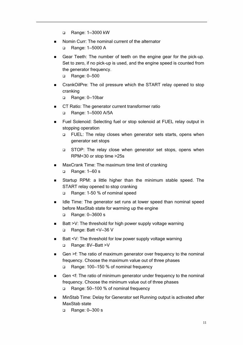
Range: 1—3000 kW
Nomin Curr: The nominal current of the alternator
Range: 1—5000 A
Gear Teeth: The number of teeth on the engine gear for the pick-up.
Set to zero, if no pick-up is used, and the engine speed is counted from
the generator frequency.
Range: 0—500
CrankOilPre: The oil pressure which the START relay opened to stop
cranking
Range: 0—10bar
CT Ratio: The generator current transformer ratio
Range: 1—5000 A/5A
Fuel Solenoid: Selecting fuel or stop solenoid at FUEL relay output in
stopping operation
FUEL: The relay closes when generator sets starts, opens when
generator set stops
STOP: The relay close when generator set stops, opens when
RPM<30 or stop time >25s
MaxCrank Time: The maximum time limit of cranking
Range: 1—60 s
Startup RPM: a little higher than the minimum stable speed. The
START relay opened to stop cranking
Range: 1-50 % of nominal speed
Idle Time: The generator set runs at lower speed than nominal speed
before MaxStab state for warming up the engine
Range: 0—3600 s
Batt >V: The threshold for high power supply voltage warning
Range: Batt <V—36 V
Batt <V: The threshold for low power supply voltage warning
Range: 8V—Batt >V
Gen >f: The ratio of maximum generator over frequency to the nominal
frequency. Choose the maximum value out of three phases
Range: 100—150 % of nominal frequency
Gen <f: The ratio of minimum generator under frequency to the nominal
frequency. Choose the minimum value out of three phases
Range: 50—100 % of nominal frequency
MinStab Time: Delay for Generator set Running output is activated after
MaxStab state
Range: 0—300 s
11

PM Hours: Next Running Hours for preventive maintenance. When
RunHours exceeding the hours, a “pm hours arrival” alarm is activated.
Set to zero if you want to leave the alarm activated
Range: 0—32767 h
AI1 Sensor Type:
AI2 Sensor Type:
AI3 Sensor Type:
Sensor Set Points
The T210 controller supports analog inputs configuration by Redit2000 software.
More information reference the software help.
NOTE!
The sensor chart supports maximum 10 characteristic. When you set less than 10 characteristic, the resistor value must be set to -1 of next point after last valid one to terminate the chart.
Contrast Adjustment
Press and hold on the DISP key until the screen enter the contrast adjustment
screen, you can adjust the best display contrast by press the DISP key, press the
RESET key to save and exit contrast adjustment page.
Language Selection
T210 support language selection between Chinese and English. Press and hold on
the DISP key on power up until the current language displayed inverted at the
top-left corner.
Starting
MANUAL mode
When the state of generator set display is Ready, press START key to
start the generator set, and then the screen displays PreStart. The
generator set begins the start procedure.
AUTO mode
If the Remote Start/Stop input is activated, the 210 controller will start
the generator set.
CAUTION
The all protection function will not work if the generator set was started not by the controller.
12

Stopping
MANUAL mode
Press STOP key will stop the running generator set.
AUTO mode
When the Remote Start/Stop input is de-activated, the running generator
set will stop after the cooling delay elapsed.
Emergence Stop
When Emergence Stop input is activated, the controller will shuts down
the generator set in emergency situation and alarm raises in Alarm List.
Protection Stop
At MANUAL mode and AUTO mode, any shutdown protection alarm
raises in Alarm List, the 210 controller will shut down the generator set.
WARNING
The running generator set will be shut down, when operation mode worked at MAINTENANCE mode.
CAUTION
Make sure the load is not present at generator before generator set starts.
13
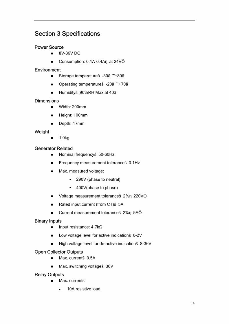
Section 3 Specifications
Power Source 8V-36V DC
Consumption: 0.1A-0.4A(at 24V)
Environment Storage temperature:-30~+80
Operating temperature:-20~+70
Humidity:90%RH Max at 40
Dimensions Width: 200mm
Height: 100mm
Depth: 4 7mm
Weight 1.0kg
Generator Related Nominal frequency:50-60Hz
Frequency measurement tolerance:0.1Hz
Max. measured voltage:
290V (phase to neutral)
400V(phase to phase)
Voltage measurement tolerance:2%(220V)
Rated input current (from CT):5A
Current measurement tolerance:2%(5A)
Binary Inputs Input resistance: 4.7kΩ
Low voltage level for active indication:0-2V
High voltage level for de-active indication:8-36V
Open Collector Outputs Max. current:0.5A
Max. switching voltage:36V
Relay Outputs Max. current:
10A resistive load
14

3A inductive load
Max. switching voltage:36V
Analog Inputs Resolution: 10bits
Sensor resistor range: 0-2.4kΩ
Speed Sensor Inputs Type of Sensor: Magnetic pick-up
Min. Input Voltage: 2Vpk-pk(4Hz to 4kHz)
Max. Input Voltage: 50V
Frequency measurement rang: 4Hz-10kHz
15

Section 4 General Troubleshooting
This section contains generator sets troubleshooting, diagnostic information.
Use the following chart to diagnose and correct common problems. The chart
includes a list of common problems, possible causes of the problem, recommended
corrective actions. If the procedures in this manual do not explain how to correct the
problem, record all the set points in field reference to Appendix C and contact an
authorized distributor/dealer.
Problem Possible Cause Corrective Action
Operation mode at
AINTENANCE mode M
Change operation
mode at MANUAL or
AUTO mode
Alarm in Alarm List don’t
disappear by press
RESET key
The alarm is activated
(display diverted in the
screen)
Correct fault activated
the alarm
Remote Off input is activated Release the input Does not enter MANUAL
or AUTO mode Self-test error on power up Contact dealer
Operation mode locked
at MANUAL or AUTO
Mode Locked input is
activated
Release the input
Engine speed displayed Check speed
correlation
Generator state display
Not Ready but no alarm
in Alarm List The generator voltage >15V Check the grounding
Prepare-fail stop alarm
arise in starting
procedure
The oil pressure is above the
CrankOilPre set point when
starting
Check the oil pressure
sensor correlation
T
out
he resistor of sensor
ranges the sensor chart
Adjust the sensor chartThe W.T. display
OPEN or SHRT,
generator set Not Ready
in clod weather The input is opened or
shorted
Check the sensor input
connections
Weak or dead battery Recharge or replace The controller display is
blank when starting and
controller reset Poor battery connections Check connections
Improper fuel Replace fuel
Air in fuel system Bleed air from system
Unit cranks but will not
start
The “Startup RPM” set point
is too small
Adjust the set point
16

Frequency display ****,
but engine speed is
normal
Load harmonics affected Improve load feature;
Mask frequency
protection by setting
“Gen >f” and “Gen <f”
set points to 100
17

Appendix A. Generator set States Table
States Description Next States
Stop Under maintain mode Not Ready, Ready
Not Ready At MANUAL or AUTO mode, there is activated alarming in the list, or the generator set is stopped, but there is still voltage or RPM ,Generator sets is not ready for starting
Ready
Ready Generator sets is ready for starting Not Ready,Starting
Prestart Pre-heat Output is activated before Cranking
Starting
Starting Start Relay Output is activated Cranking
Cranking Engine cranking sequence in process Not Ready, Ready, Idle,Pause
Idle Waiting for generator sets to warm up, Idle Output is activated
Over SPD, MaxStab, Fail Stop
Under SPD
Running at engine speed under rated on
Fail Stop
Over SPD Running at engine speed over rated on
Fail Stop
Pause Waiting before next start attempts in the auto start procedure
Starting
MaxStab Generator sets waiting to get proper voltage level after reaching of defined level of RPM
Under SPD, Over SPD, AVR Fail, MinStab
MinStab Generator sets waiting for loaded after got proper voltage level
Running, Over SPD, Fail Stop, RPM Fail, Under SPD
AVR Fail Generator sets fail to get proper voltage level in MaxStab state
Fail Stop
RPM Fail Engine speed is under Startup RPM Fail Stop
Fail Stop Generator sets stop by alarm of failure Not Ready, Ready
Running Generator sets is running, ready to load anytime
Under SPD, Over SPD, Cooling, Fail Stop, RPM Fail
Cooling Generator sets is cooling before stop Not Ready, Ready, Fail Stop, Running
18

Appendix B. Alarm Event
Event Description
fail-stop stop Stopping sequence activated when unsuccessful Generator sets Stop happening
emerg stop Emergency stop activated
o.p. sw alm Oil pressure switch alarm
w.t. sw alm Coolant temperature switch alarm
f.l. sw alm Fuel level switch alarm
o.p. sen. Pre_alm Oil pressure sensor pre-alarm under “O.P. Lev1” set point)
o.p. sen alm Oil pressure sensor alarm(under “O.P. Lev2” set point)
w.t. sen. Pre-alm Coolant temperature sensor pre-alarm(above “W.T. Lev1” set point)
w.t. sen. alm Coolant temperature sensor pre-alarm (above “W.T. Lev1” set point)
f.l. sen. Pre-alm Fuel level sensor pre-alarm(under “F.L. Lev1” set point)
f.l. sen. alm Fuel level sensor alarm(under “F.L. Lev2” set point)
high batt High battery voltage alarm(above “Batt>V” set point)
low batt Low battery voltage alarm(under “Batt<V” set point)
v-batt under stop Generator sets stop by battery alarm
gen freq alm Generator frequency alarm
vg1 alm Generator phase 1 voltage alarm
vg2 alm Generator phase 2 voltage alarm
vg3 alm Generator phase 3 voltage alarm
gen-fail stop Generator voltage not present in MaxStab state
ig unbal Generator current unbalance
vg unbal alm Generator voltage unbalance
ig-short Generator current over “Curr Short” set point
ig-over Generator current over “Curr Over” set point
active power over Generator active power over “Curr Over” set point
19

under-speed stop Generator set under speed stop
over-speed stop Generator set over speed stop
start-fail stop Generator set continued start fail at AUTO mode
pm hours arrival Generator set preventive maintenance hours is overtime
20

Appendix C. User Defined Settings
Program version of the controller
Serial Number
Below is all the set points for T210.
Set Points Range Setting Default Setting
User Defined Setting
Nomin Power (kW) 1—3000 100
Nomin Volt (V) 80—300 230
Nomin Curr (A) 1—5000 200
Nomin Freq (Hz) 45—65 50
Nomin RPM (r/min) 100-4000 1500
Gear Teeth 0—500 0
CT Ratio (/5A) 1—5000 200
Fuel Solenoid Fuel/Stop Fuel
PreStart Time (s) 0-600 0
Idle Time (s) 0—3600 0
Crank Attempts 1—10 3
CrankOilPre (bar) 0-10 3
Start Delay (s) 0—600 5
Startup RPM (%) 1—50% of Nominal RPM 25
MaxCrank Time (s) 1—60 10
CrankFail Pause (s) 5—60 30
MinStab Time (s) 0-300 0
MaxStab Time (s) 0—300 60
Cooling Time (s) 0—3600 180
PM Hours (h) 0-32767 0 Underspeed (%) 0-100 90
UnderspeedDel 0-600 10
Overspeed (%) 100-150% of Nominal RPM 110
OverspeedDel (s) 0-3 3
Protection Del (s) 0—300 15
Horn Timeout (s) 0—600 60
Batt >V (V) 8—36 31
Batt <V (V) 8—Batt >V 20
Batt V Delay (s) 0—600 60
W.T. Lev1 () 0—9999 95
W.T. Lev2 () 0—9999 100
W.T. Del (s) 0—180 10
O.P. Lev1 (Bar) 0—999.9 2.0
O.P. Lev2 (Bar) 0—999.9 1.5
O.P. Del (s) 0—180 10
F.L. Lev1 (%) 0—100 20
F.L. Lev2 (%) 0—100 10
21

F.L. Del (s) 0—180 30
Curr Over (%) 100—300% of Nominal current
105
Curr Over Del(s) 0.0—600.0 30
Curr Short (%) 100—500% of Nominal current
150
Curr Short Del (s) 0.0—600.0 1
Curr Unbal (%) 1—100% of Nominal current 45
Current Unbal Del (s) 0.0—600.0 30
Gen >V (%) 100—150% of Nominal Voltage
120
Gen <V (%) 50—100% of Nominal Voltage
80
Gen V Del (s) 0.0—600.0 10
Gen >f (%) 100—150% of Nominal Frequency
110
Gen <f (%) 50—100% of Nominal Frequency
90
Gen f Del (s) 0.0—600.0 8
(Gen)Volt Unbal (%) 1—150% 25
(Gen)Volt Unbal Del (s) 0.0—600.0 5
Password 0—9999 0
GName --
Language Chinese/English Chinese
Below is Analog Inputs, Binary Inputs and Open Collect Outputs setting
Channel Name
Default Setting User Defined Setting
Notes
Name: W.T.
Unit:
Type: VDO AI1
Alarm Action: Masked
Name: O.P.
Unit: Bar
Type: VDO AI2
Alarm Action: Masked
Name: F.L.
Unit: %
Type: Not Defined AI3
Alarm Action: Masked
Name: Emergence Stop
Polarity: Open to active BI1
Alarm Action: ---
Name: Remote Start/Stop
Polarity: Close to active BI2
Alarm Action: ---
22

Name: Oil pressure switch
Polarity: Close to active BI3 Alarm Action: Unload Shutdown
Name: Coolant temperature switch
Polarity: Close to active BI4
Alarm Action: Cool down
Name: Mode Input 0
Polarity: Close to active BI5
Alarm Action: ---
Name: Alarm Horn Output BO1
Polarity: Close to active
Name: Running Output BO2
Polarity: Close to active
Name: Idle Control Output BO3
Polarity: Open to active
23