Embed Size (px)
Citation preview
1
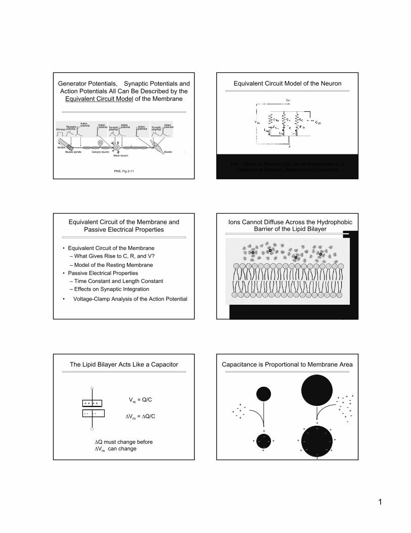
Generator Potentials, �Synaptic Potentials and Action Potentials All Can Be Described by the
Equivalent Circuit Model of the Membrane
PNS, Fig 2-11
The �Nerve (or Muscle) Cell can be Represented by aCollection of Batteries, Resistors and Capacitors
Equivalent Circuit Model of the Neuron
• Equivalent Circuit of the Membrane– What Gives Rise to C, R, and V?– Model of the Resting Membrane
• Passive Electrical Properties– Time Constant and Length Constant– Effects on Synaptic Integration
• �Voltage-Clamp Analysis of the Action Potential
Equivalent Circuit of the Membrane andPassive Electrical Properties
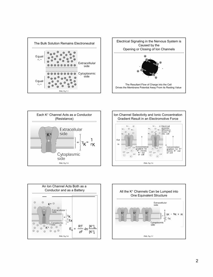
Ions Cannot Diffuse Across the Hydrophobic Barrier of the Lipid Bilayer
+ + + +
- - - -
Vm = Q/C
∆Vm = ∆Q/C
The Lipid Bilayer Acts Like a Capacitor
∆Q must change before∆Vm can change
Capacitance is Proportional to Membrane Area
------
--
--
------
-- --
--
---- ---- --
--
--
--
--+
+
+
+
+
+
+ +
+
+ +
+
+
+
+ +--
----
--+
++
++
+
+
+
2
The Bulk Solution Remains Electroneutral
PNS, Fig 7-1
Electrical Signaling in the Nervous System isCaused by the
Opening or Closing of Ion Channels
--
----
--
--
--
----+
+
+
+
+
+
+
+
+
+
+
+
--
The Resultant Flow of Charge into the CellDrives the Membrane Potential Away From its Resting Value
Each K+ Channel Acts as a Conductor (Resistance)
PNS, Fig 7-5
Ion Channel Selectivity and Ionic Concentration Gradient Result in an Electromotive Force
PNS, Fig 7-3
An Ion Channel Acts Both as aConductor and as a Battery
RT [K+]ozF [K+]i
•lnEK =
PNS, Fig 7-6
All the K+ Channels Can be Lumped into One Equivalent Structure
PNS, Fig 7-7
3
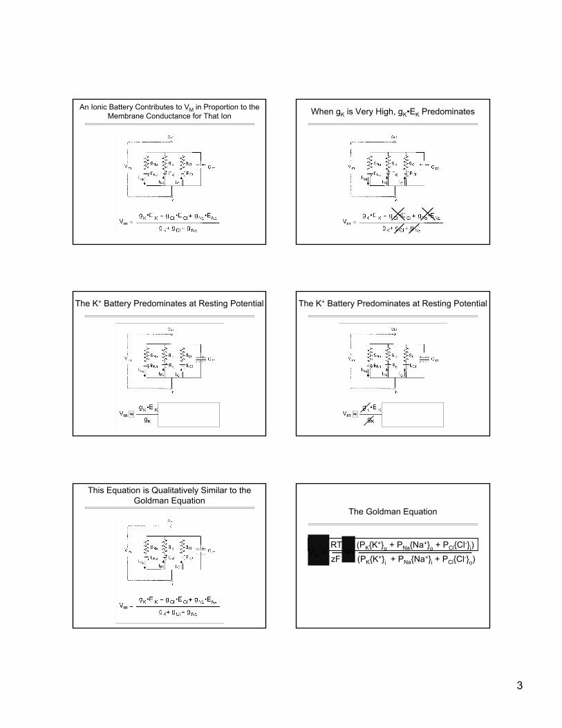
An Ionic Battery Contributes to VM in Proportion to the Membrane Conductance for That Ion When gK is Very High, gK•EK Predominates
The K+ Battery Predominates at Resting Potential
gK≈
The K+ Battery Predominates at Resting Potential
gK≈
This Equation is Qualitatively Similar to theGoldman Equation
Vm = RT•ln (PK{K+}o + PNa{Na+}o + PCl{Cl-}i)zF (PK{K+}i + PNa{Na+}i + PCl{Cl-}o)
•lnVm =
The Goldman Equation
4
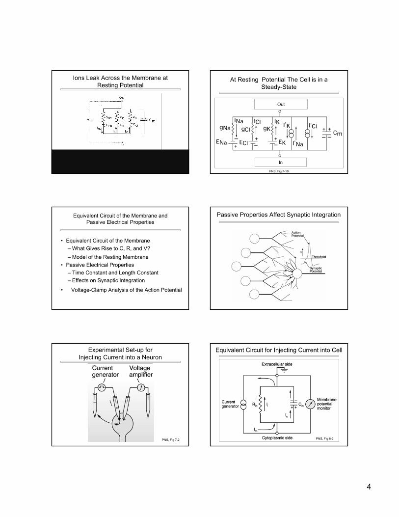
Ions Leak Across the Membrane atResting Potential
At Resting Potential The Cell is in aSteady-State
In
Out
PNS, Fig 7-10
• Equivalent Circuit of the Membrane– What Gives Rise to C, R, and V?– Model of the Resting Membrane
• Passive Electrical Properties– Time Constant and Length Constant– Effects on Synaptic Integration
• �Voltage-Clamp Analysis of the Action Potential
Equivalent Circuit of the Membrane andPassive Electrical Properties
Passive Properties Affect Synaptic Integration
Experimental Set-up forInjecting Current into a Neuron
PNS, Fig 7-2
Equivalent Circuit for Injecting Current into Cell
PNS, Fig 8-2
5
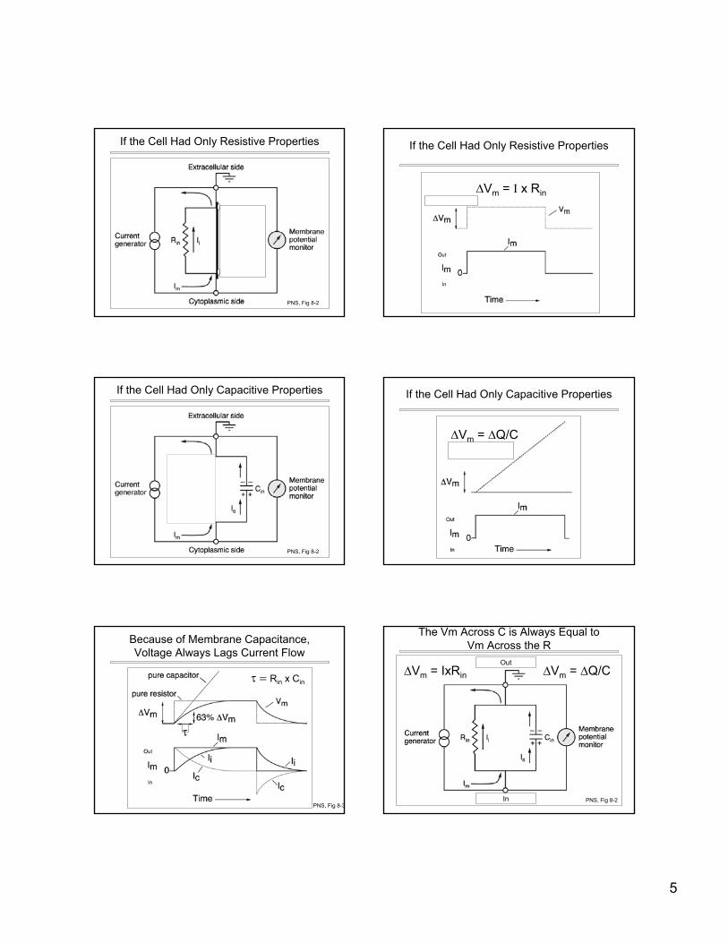
If the Cell Had Only Resistive Properties
PNS, Fig 8-2
If the Cell Had Only Resistive Properties
∆Vm = I x Rin
If the Cell Had Only Capacitive Properties
PNS, Fig 8-2
If the Cell Had Only Capacitive Properties
∆Vm = ∆Q/C
Because of Membrane Capacitance,Voltage Always Lags Current Flow
τ
τ = Rin x Cin
PNS, Fig 8-3
The Vm Across C is Always Equal toVm Across the R
∆Vm = ∆Q/C∆Vm = IxRin
In
Out
PNS, Fig 8-2
6
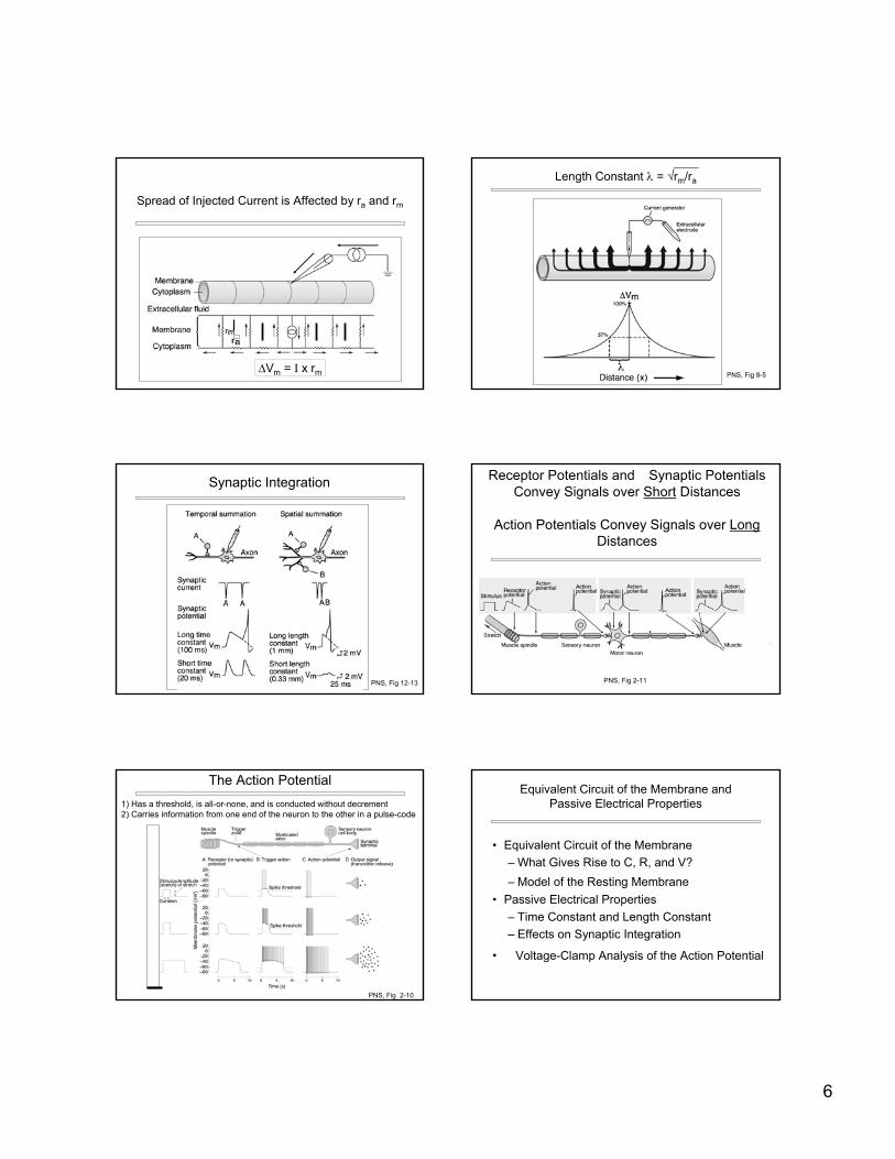
Spread of Injected Current is Affected by ra and rm
∆Vm = I x rm
Length Constant λ = √rm/ra
PNS, Fig 8-5
Synaptic Integration
PNS, Fig 12-13
Receptor Potentials and �Synaptic Potentials Convey Signals over Short Distances
Action Potentials Convey Signals over LongDistances
PNS, Fig 2-11
1) Has a threshold, is all-or-none, and is conducted without decrement2) Carries information from one end of the neuron to the other in a pulse-code
The Action Potential
PNS, Fig 2-10
• Equivalent Circuit of the Membrane– What Gives Rise to C, R, and V?– Model of the Resting Membrane
• Passive Electrical Properties– Time Constant and Length Constant– Effects on Synaptic Integration
• �Voltage-Clamp Analysis of the Action Potential
Equivalent Circuit of the Membrane andPassive Electrical Properties
7
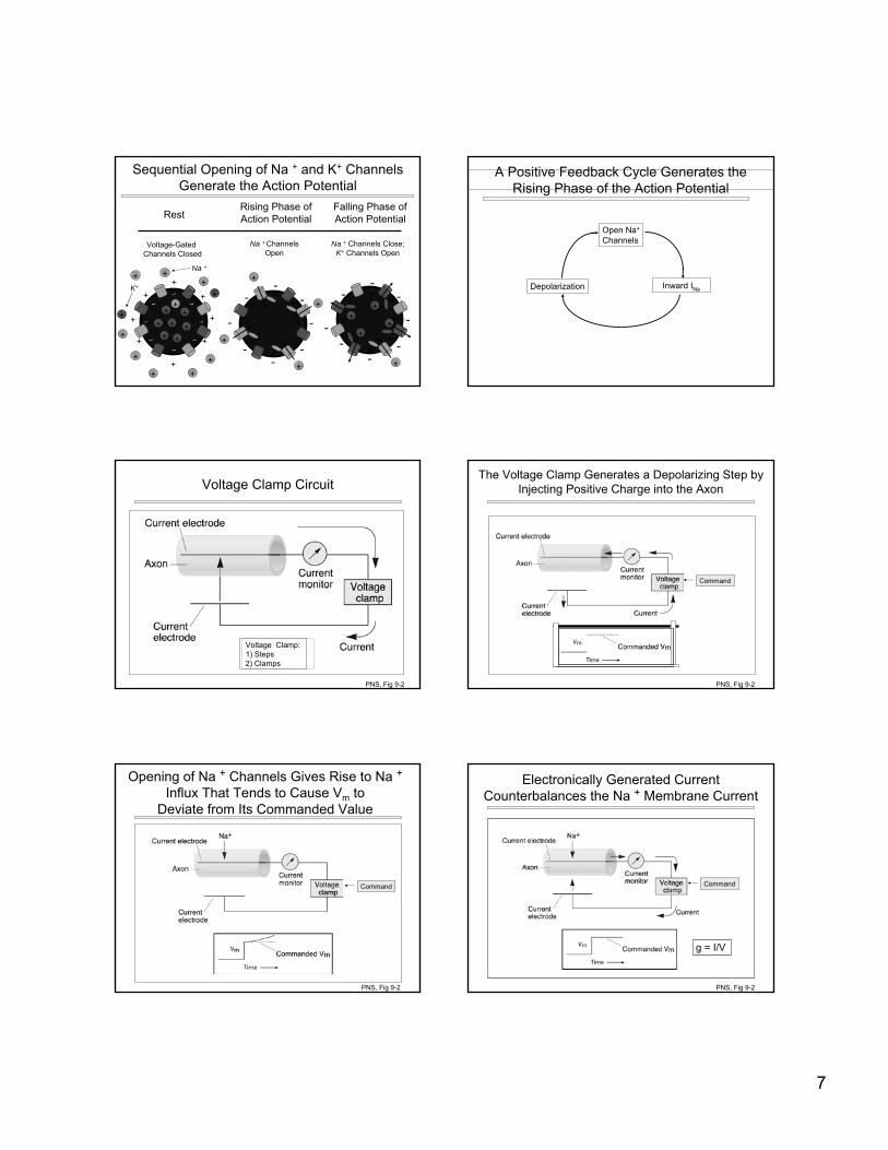
Sequential Opening of Na + and K+ Channels Generate the Action Potential
----
--
----
--
----+
+
+
+
+
+
+
+
--
----
--
--
--
----+
+
+
+
+
+
+
+
+
+
+
+
----
--
--
--
--
----
+
+
+
+
+
+
+
+
+
+
++
+
Rising Phase ofAction PotentialRest
Falling Phase ofAction Potential
Na + ChannelsOpen
Na + Channels Close;K+ Channels Open
Voltage-Gated Channels Closed
+ +
+ ++
+
+
+
+ ++
+
+
++
+
+
+
Na +
K+
A Positive Feedback Cycle Generates theRising Phase of the Action Potential
Depolarization
Open Na+
Channels
Inward INa
Voltage Clamp Circuit
Voltage Clamp:1) Steps2) Clamps
PNS, Fig 9-2
The Voltage Clamp Generates a Depolarizing Step by Injecting Positive Charge into the Axon
Command
PNS, Fig 9-2
Opening of Na + Channels Gives Rise to Na +Influx That Tends to Cause Vm to
Deviate from Its Commanded Value
Command
PNS, Fig 9-2
Electronically Generated Current Counterbalances the Na + Membrane Current
Command
g = I/V
PNS, Fig 9-2
8
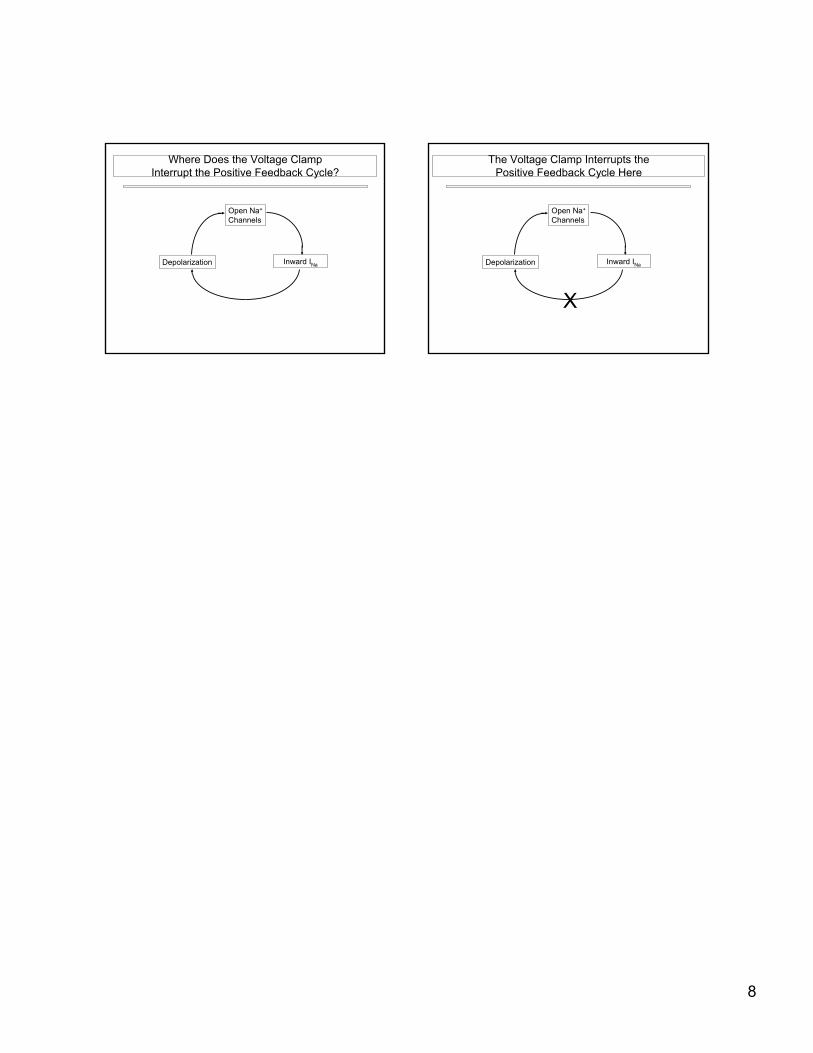
Where Does the Voltage ClampInterrupt the Positive Feedback Cycle?
Depolarization
Open Na+
Channels
Inward INa
The Voltage Clamp Interrupts thePositive Feedback Cycle Here
Depolarization
Open Na+
Channels
Inward INa
X


![Inward rectifying currents stabilize the membrane ... · distal dendrites [20,21], where I (H) shortens the decay time course of excitatory post-synaptic potentials (EPSP) and af-fects](https://img.pdfslide.us/doc/110x75/608f3d31a48d4839c2485827/inward-rectifying-currents-stabilize-the-membrane-distal-dendrites-2021.jpg)