Embed Size (px)
Citation preview
BCEdkS'
Generator Interconnection System Impact Study for
SCE&G V.C. Summer Nuclear #3
Prepared for: SCE&G Nuclear Group
August 31, 2007
Prepared by: SCE&G Transmission Planning
Exhibit Q-2 (Exhibit No. _____ (HCY-2)) Page 1 of 22

2
TABLE OF CONTENTS
General Discussion........................................................................ Page 3
I. Generator Information ............................................................... Page 5 II. Transmission Studies................................................................ Page 5
a. Power Flow Analysis ..................................................... Page 5 b. Short Circuit Analysis .................................................... Page 7 c. Stability Analysis ........................................................... Page 7
III. Required Interconnection Facilities ......................................... Page 17
IV. Engineering Design & Cost ..................................................... Page 19
a. Engineering Single Line Layout ................................... Page 19 b. Transmission & Substation Cost.................................. Page 22
Exhibit Q-2 (Exhibit No. _____ (HCY-2)) Page 2 of 22
3
Generator Interconnection System Impact Study for
SCE&G V.C. Summer Nuclear #3
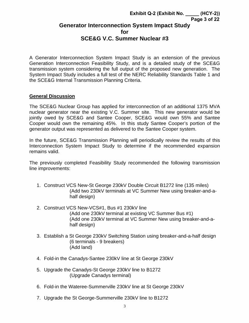
A Generator Interconnection System Impact Study is an extension of the previous Generation Interconnection Feasibility Study, and is a detailed study of the SCE&G transmission system considering the full output of the proposed new generation. The System Impact Study includes a full test of the NERC Reliability Standards Table 1 and the SCE&G Internal Transmission Planning Criteria. General Discussion The SCE&G Nuclear Group has applied for interconnection of an additional 1375 MVA nuclear generator near the existing V.C. Summer site. This new generator would be jointly owed by SCE&G and Santee Cooper, SCE&G would own 55% and Santee Cooper would own the remaining 45%. In this study Santee Cooper’s portion of the generator output was represented as delivered to the Santee Cooper system. In the future, SCE&G Transmission Planning will periodically review the results of this Interconnection System Impact Study to determine if the recommended expansion remains valid. The previously completed Feasibility Study recommended the following transmission line improvements:
1. Construct VCS New-St George 230kV Double Circuit B1272 line (135 miles) (Add two 230kV terminals at VC Summer New using breaker-and-a-half design)
2. Construct VCS New-VCS#1, Bus #1 230kV line
(Add one 230kV terminal at existing VC Summer Bus #1) (Add one 230kV terminal at VC Summer New using breaker-and-a-half design)
3. Establish a St George 230kV Switching Station using breaker-and-a-half design
(6 terminals - 9 breakers) (Add land)
4. Fold-in the Canadys-Santee 230kV line at St George 230kV
5. Upgrade the Canadys-St George 230kV line to B1272
(Upgrade Canadys terminal)
6. Fold-in the Wateree-Summerville 230kV line at St George 230kV
7. Upgrade the St George-Summerville 230kV line to B1272
Exhibit Q-2 (Exhibit No. _____ (HCY-2)) Page 3 of 22
4
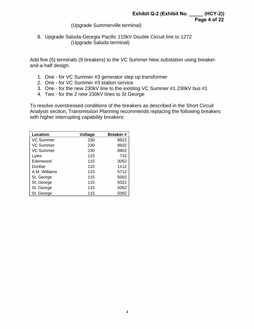
(Upgrade Summerville terminal)
8. Upgrade Saluda-Georgia Pacific 115kV Double Circuit line to 1272 (Upgrade Saluda terminal)
Add five (5) terminals (9 breakers) to the VC Summer New substation using breaker-and-a-half design.
1. One - for VC Summer #3 generator step up transformer 2. One - for VC Summer #3 station service 3. One - for the new 230kV line to the existing VC Summer #1 230kV bus #1 4. Two - for the 2 new 230kV lines to St George
To resolve overstressed conditions of the breakers as described in the Short Circuit Analysis section, Transmission Planning recommends replacing the following breakers with higher interrupting capability breakers: Location Voltage Breaker #VC Summer 230 8822VC Summer 230 8932VC Summer 230 8902Lyles 115 732Edenwood 115 3052Dunbar 115 1112A.M. Williams 115 5712St. George 115 5002St. George 115 5022St. George 115 5052St. George 115 5082
Exhibit Q-2 (Exhibit No. _____ (HCY-2)) Page 4 of 22

5
I. Generator Information The generator design consists of a single nuclear unit and one step-up transformer. The generator unit will have a maximum gross MVA output capacity of 1,375 MVA and a maximum continuous net MW of 1,165 MW. The generator design consists of the following information:
MVA – gross: 1375 MW – net: 1165 Power Factor: between .90 and 1.05 Voltage: 26kV Speed: 1800 rpm X’d-sat.: 0.397 PU; X’’d-sat.: 0.261 PU X2-sat.: 0.261 PU; X0: 0.176 PU
II. Transmission Studies
A. Power Flow Analysis Since the completion of the Generation Interconnection Feasibility Study, modifications were made to the 230kV generator substation layout and the arrangement of lines connecting to the existing V.C. Summer substation and the proposed V.C. Summer substation. These changes resulted in the proposed retirement of the Parr 230kV substation. The original improvements along with these proposed modifications were modeled and Transmission Planning has run more detailed power flow analysis of the SCE&G transmission system to include a full test of the NERC Reliability Standards Table 1 and the SCE&G Internal Transmission Planning Criteria. Three different projected loading conditions were simulated for the 2019 time period: Summer Peak Load, Shoulder Load (75% of peak) and Light Load (38% of peak). For the Summer Peak Load and Shoulder Load simulations, the analysis identified no additional overload conditions due to the additional generation that had not already been previously identified in the Feasibility Study. However, for the Light Load simulation, the following new conditions occurred: In the basecase, with no outages, the VC Summer-Newport (Duke) 230kV line loads to 98% of its continuous rating of 437 MVA.
Exhibit Q-2 (Exhibit No. _____ (HCY-2)) Page 5 of 22

6
The n-2 analyses show the following overload conditions due to the additional generation: Rating Loading Overloaded Facility (MVA) (%) Contingency(s)
VC Summer #1 bus #2-Newport (Duke) 230kV line 456 104
VC Summer #1 bus #1-Winnsboro (Santee Cooper) 230kV line and VC Summer #1 bus #1-Blythewood (Santee Cooper) 230kV line
VC Summer #1 bus #2-Newport (Duke) 230kV line 456 104
VC Summer New-Pomaria (Santee Cooper) 230kV line #1 and VC Summer New-Pomaria (Santee Cooper) 230kV line #2
VC Summer #1 bus #2-Newport (Duke) 230kV line 456 103
VC Summer New-Bush River (Duke) 230kV line and VC Summer #1 bus #1-Blythewood (Santee Cooper) 230kV line
VC Summer #1 bus #2-Newport (Duke) 230kV line 456 103
VC Summer New-Bush River (Duke) 230kV line and VC Summer #1 bus #1-Winnsboro (Santee Cooper) 230kV line
VC Summer #1 bus #2-Newport (Duke) 230kV line 456 101
VC Summer New-Bush River (Duke) 230kV line and VC Summer New-Ward 230kV line
VC Summer #1 bus #2-Newport (Duke) 230kV line 456 101
VC Summer New-Bush River (Duke) 230kV line and VC Summer New-St George 230kV line
The installation of a series reactor on the VC Summer #1-Newport (Duke) 230kV line will reduce the current flow on the line and eliminate these conditions.
Exhibit Q-2 (Exhibit No. _____ (HCY-2)) Page 6 of 22

7
B. Short Circuit Analysis
The previously completed feasibility study indicated three 230kV breakers and eight 115kV breakers were overstressed due to the additional generation at V. C. Summer and must be replaced. This analysis identified no overstressed breakers due to the additional generation that had not already been previously identified in the Feasibility study. The addition of the VC Summer #3 unit will increase the fault current in the VC Summer area to the point where 80kA breakers will be approaching the point of becoming overstressed. As the fault current capability of the interconnected transmission system increases in the future, this will require breakers with larger interrupting capability. C. Stability Analysis 1. Overview of Stability Analysis. The stability study of the connection of the V.C. Summer #3 AP1000 generator to the SCE&G transmission system assessed the ability of this generator to remain in synchronism following selected transmission system contingencies. Also reviewed were the adequacy of damping of generation/transmission oscillations and the impact of the proposed generator on the stability performance of other system generators. System voltage responses were examined for indications of voltage instability. In addition, generator frequency responses and the effects of protective system performance were evaluated. For the system peak load cases, the adjacent V.C. Summer #2 generator was simulated as switched off except for where noted as otherwise. In addition, the 230kV transmission line connecting the V.C. Summer #3 generator switchyard to SCE&G’S Denny Terrace substation was switched out. These outages were simulated in order to account for the possibility that major generation and transmission could be out of service during the operation of the connecting facility. Power flow studies showed that these were the generation and transmission outages that resulted in the greatest impact on the reactive output of the V.C. Summer #3 generator. Rotor angle responses of the V.C. Summer #3 generator were simulated in order to determine if angular instability could result from likely contingencies. Generator frequency deviations were examined in order to determine if generator frequency protection could result in generator tripping. The results of the loss of the V.C. Summer #3 generator were examined in order to determine if any resulting underfrequency relay operations would lead to system load shedding. Finally, the effects of each contingency on the V.C. Summer #2 & #3 230kV switchyard bus were examined along with voltages at the existing V.C. Summer #1 230kV and 115kV Offsite Power Supply buses to determine if the voltage requirements of the Offsite Power Supply buses were violated. Generator response plots are not included but are available for review upon request.
Exhibit Q-2 (Exhibit No. _____ (HCY-2)) Page 7 of 22
8
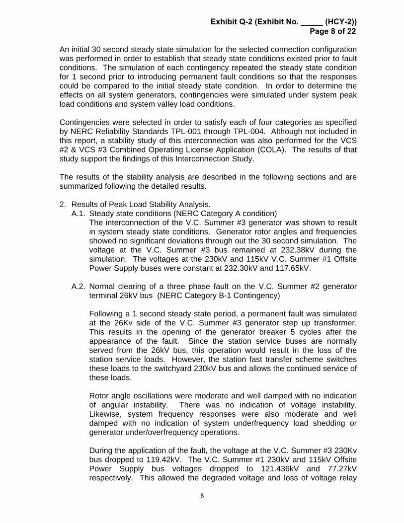
An initial 30 second steady state simulation for the selected connection configuration was performed in order to establish that steady state conditions existed prior to fault conditions. The simulation of each contingency repeated the steady state condition for 1 second prior to introducing permanent fault conditions so that the responses could be compared to the initial steady state condition. In order to determine the effects on all system generators, contingencies were simulated under system peak load conditions and system valley load conditions. Contingencies were selected in order to satisfy each of four categories as specified by NERC Reliability Standards TPL-001 through TPL-004. Although not included in this report, a stability study of this interconnection was also performed for the VCS #2 & VCS #3 Combined Operating License Application (COLA). The results of that study support the findings of this Interconnection Study. The results of the stability analysis are described in the following sections and are summarized following the detailed results. 2. Results of Peak Load Stability Analysis. A.1. Steady state conditions (NERC Category A condition)
The interconnection of the V.C. Summer #3 generator was shown to result in system steady state conditions. Generator rotor angles and frequencies showed no significant deviations through out the 30 second simulation. The voltage at the V.C. Summer #3 bus remained at 232.38kV during the simulation. The voltages at the 230kV and 115kV V.C. Summer #1 Offsite Power Supply buses were constant at 232.30kV and 117.65kV.
A.2. Normal clearing of a three phase fault on the V.C. Summer #2 generator
terminal 26kV bus (NERC Category B-1 Contingency)
Following a 1 second steady state period, a permanent fault was simulated at the 26Kv side of the V.C. Summer #3 generator step up transformer. This results in the opening of the generator breaker 5 cycles after the appearance of the fault. Since the station service buses are normally served from the 26kV bus, this operation would result in the loss of the station service loads. However, the station fast transfer scheme switches these loads to the switchyard 230kV bus and allows the continued service of these loads. Rotor angle oscillations were moderate and well damped with no indication of angular instability. There was no indication of voltage instability. Likewise, system frequency responses were also moderate and well damped with no indication of system underfrequency load shedding or generator under/overfrequency operations. During the application of the fault, the voltage at the V.C. Summer #3 230Kv bus dropped to 119.42kV. The V.C. Summer #1 230kV and 115kV Offsite Power Supply bus voltages dropped to 121.436kV and 77.27kV respectively. This allowed the degraded voltage and loss of voltage relay
Exhibit Q-2 (Exhibit No. _____ (HCY-2)) Page 8 of 22

9
timers to initiate. However, the voltages recovered enough to reset the timers within 1 cycle of the clearing of the fault. Steady state conditions were reestablished with no further system operations.
A.3. Delayed clearing of a single line to ground fault on the future V.C. Summer #2 & #3 switchyard to the existing V.C. Summer #1 generator switchyard bus #1 (NERC Category C-8 contingency)
Since this contingency places a fault near the existing V.C. Summer #1 generator and both future VCS #2 & #3 generators, these units were modeled as switched on. All local transmission lines were also modeled as in service. Following a 1 second steady state period, a permanent single phase-to-ground fault was simulated at the V.C. Summer #2 & #3 end of the V.C. Summer #2 & #3 – V.C. Summer #1 230kV transmission line #1. The circuit breaker at the V.C. Summer #1 end of the line was simulated as operating normally. The breaker and a half scheme at the V.C. Summer #2 & #3 switchyard cleared the fault following a fault duration of approximately 0.25 seconds. During the application of the fault, the voltage at the V.C. Summer #2 & #3 bus dropped to 107.12kV. The V.C. Summer #1 230kV and 115kV Offsite Power Supply bus voltages dropped to 109.64kV and 62.11kV respectively. This allowed the degraded voltage and loss of voltage relay timers to initiate. The voltages did not recover in time to reset the loss of voltage relay timers within the required 0.24 seconds of the appearance of the fault. Consequently, both the 230kV and the 115kV loss of voltage relays will operate, resulting in a loss of offsite power and switching of the Engineered Safeguard Features 7.2kV buses to the diesel generators. This operation is not caused by the VCS #3 generator since any nearby fault with delayed clearing will depress the VCS#1 230kV switchyard and local 115kV transmission system voltages for a longer period of time than the VCS #1 loss of voltage relay timers are set for.
Rotor angle oscillations for local generators were pronounced but were adequately damped with no indication of angular instability. There was no indication of voltage instability. Likewise, system frequency responses were also moderate and adequately damped with no indication of system underfrequency load shedding or generator under/overfrequency operations. Steady state conditions were reestablished with no further system operations.
A.4. Normal clearing of a three phase fault on the existing V.C. Summer #1 generator switchyard bus #1 (NERC Category D-10 contingency)
Exhibit Q-2 (Exhibit No. _____ (HCY-2)) Page 9 of 22
10
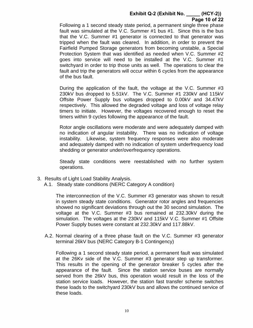
Following a 1 second steady state period, a permanent single three phase fault was simulated at the V.C. Summer #1 bus #1. Since this is the bus that the V.C. Summer #1 generator is connected to that generator was tripped when the fault was cleared. In addition, in order to prevent the Fairfield Pumped Storage generators from becoming unstable, a Special Protection System that was identified as needed when V.C. Summer #2 goes into service will need to be installed at the V.C. Summer #1 switchyard in order to trip those units as well. The operations to clear the fault and trip the generators will occur within 6 cycles from the appearance of the bus fault. During the application of the fault, the voltage at the V.C. Summer #3 230kV bus dropped to 5.51kV. The V.C. Summer #1 230kV and 115kV Offsite Power Supply bus voltages dropped to 0.00kV and 34.47kV respectively. This allowed the degraded voltage and loss of voltage relay timers to initiate. However, the voltages recovered enough to reset the timers within 9 cycles following the appearance of the fault. Rotor angle oscillations were moderate and were adequately damped with no indication of angular instability. There was no indication of voltage instability. Likewise, system frequency responses were also moderate and adequately damped with no indication of system underfrequency load shedding or generator under/overfrequency operations. Steady state conditions were reestablished with no further system operations.
3. Results of Light Load Stability Analysis. A.1. Steady state conditions (NERC Category A condition)
The interconnection of the V.C. Summer #3 generator was shown to result in system steady state conditions. Generator rotor angles and frequencies showed no significant deviations through out the 30 second simulation. The voltage at the V.C. Summer #3 bus remained at 232.30kV during the simulation. The voltages at the 230kV and 115kV V.C. Summer #1 Offsite Power Supply buses were constant at 232.30kV and 117.88kV.
A.2. Normal clearing of a three phase fault on the V.C. Summer #3 generator terminal 26kV bus (NERC Category B-1 Contingency)
Following a 1 second steady state period, a permanent fault was simulated at the 26Kv side of the V.C. Summer #3 generator step up transformer. This results in the opening of the generator breaker 5 cycles after the appearance of the fault. Since the station service buses are normally served from the 26kV bus, this operation would result in the loss of the station service loads. However, the station fast transfer scheme switches these loads to the switchyard 230kV bus and allows the continued service of these loads.
Exhibit Q-2 (Exhibit No. _____ (HCY-2)) Page 10 of 22

11
Rotor angle oscillations were small but poorly damped due to the smaller level of synchronizing torque within the system due to the reduced amount of generation on line during system low load conditions. However, the generator rotor angle oscillations were eventually damped and there was no indication of angular instability. There was no indication of voltage instability. Likewise, system frequency responses were also small and poorly damped but with no indication of system underfrequency load shedding or generator under/overfrequency operations.
During the application of the fault, the voltage at the V.C. Summer #3 bus dropped to 125.70kV. The V.C. Summer #1 230kV and 115kV Offsite Power Supply bus voltages dropped to 127.60kV and 72.95kV respectively. This allowed the degraded voltage and loss of voltage relay timers to initiate. However, the voltages recovered enough to reset the timers within 1 cycle of the clearing of the fault. Steady state conditions were reestablished with no further system operations.
A.3. Delayed clearing of a single line to ground fault on the future V.C. Summer #2 & #3 switchyard to the existing V.C. Summer #1 generator switchyard bus #2 (NERC Category C-8 contingency)
Following a 1 second steady state period, a permanent single phase-to-ground fault was simulated at the V.C. Summer #2 & #3 end of the V.C. Summer #2 & #3 – V.C. Summer #1 230kV transmission line #1. The circuit breaker at the V.C. Summer #1 end of the line was simulated as operating normally. The breaker and a half scheme at the V.C. Summer #2 & #3 switchyard cleared the fault following a fault duration of approximately 0.25 seconds. During the application of the fault, the voltage at the V.C. Summer #2 & #3 bus dropped to 98.93kV. The V.C. Summer #1 230kV and 115kV Offsite Power Supply bus voltages dropped to 101.03kV and 60.79kV respectively. This allowed the degraded voltage and loss of voltage relay timers to initiate. The voltages did not recover in time to reset the loss of voltage relay timers within the required 0.24 seconds of the appearance of the fault. Consequently, both the 230kV and the 115kV loss of voltage relays will operate, resulting in a loss of offsite power and switching of the Engineered Safeguard Features 7.2kV buses to the diesel generators. This operation is not caused by the VCS #3 generator since any nearby fault with delayed clearing will depress the VCS #1 230kV switchyard and local 115kV transmission system voltages for a longer period of time than the VCS #1 loss of voltage relay timers are set for.
Rotor angle oscillations were large and were poorly damped due to the reduced generation during light load conditions and the resulting reduction in system synchronizing torque. An extended simulation showed that the generator rotor angle oscillations were eventually damped and there was no indication of angular instability. There was no indication of voltage
Exhibit Q-2 (Exhibit No. _____ (HCY-2)) Page 11 of 22
12
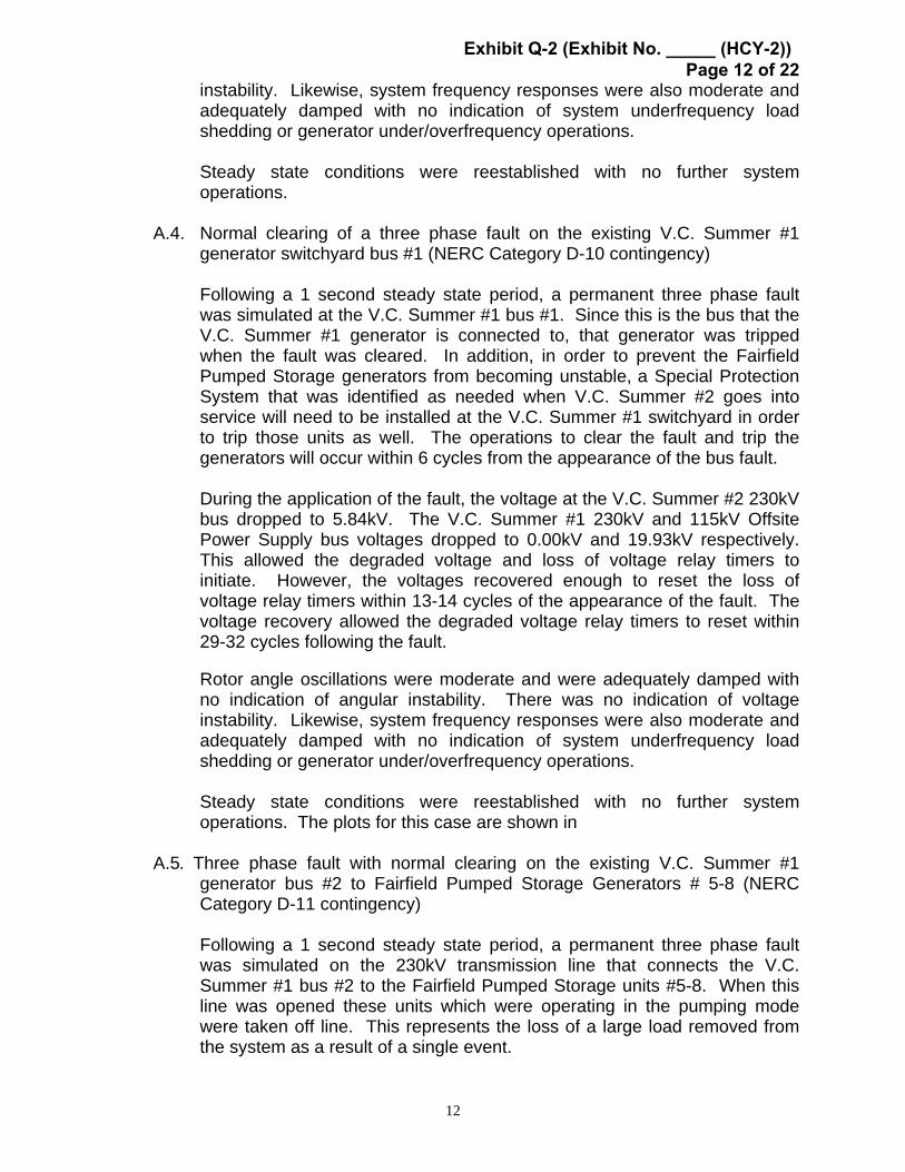
instability. Likewise, system frequency responses were also moderate and adequately damped with no indication of system underfrequency load shedding or generator under/overfrequency operations. Steady state conditions were reestablished with no further system operations.
A.4. Normal clearing of a three phase fault on the existing V.C. Summer #1 generator switchyard bus #1 (NERC Category D-10 contingency)
Following a 1 second steady state period, a permanent three phase fault was simulated at the V.C. Summer #1 bus #1. Since this is the bus that the V.C. Summer #1 generator is connected to, that generator was tripped when the fault was cleared. In addition, in order to prevent the Fairfield Pumped Storage generators from becoming unstable, a Special Protection System that was identified as needed when V.C. Summer #2 goes into service will need to be installed at the V.C. Summer #1 switchyard in order to trip those units as well. The operations to clear the fault and trip the generators will occur within 6 cycles from the appearance of the bus fault. During the application of the fault, the voltage at the V.C. Summer #2 230kV bus dropped to 5.84kV. The V.C. Summer #1 230kV and 115kV Offsite Power Supply bus voltages dropped to 0.00kV and 19.93kV respectively. This allowed the degraded voltage and loss of voltage relay timers to initiate. However, the voltages recovered enough to reset the loss of voltage relay timers within 13-14 cycles of the appearance of the fault. The voltage recovery allowed the degraded voltage relay timers to reset within 29-32 cycles following the fault. Rotor angle oscillations were moderate and were adequately damped with no indication of angular instability. There was no indication of voltage instability. Likewise, system frequency responses were also moderate and adequately damped with no indication of system underfrequency load shedding or generator under/overfrequency operations.
Steady state conditions were reestablished with no further system operations. The plots for this case are shown in
A.5. Three phase fault with normal clearing on the existing V.C. Summer #1
generator bus #2 to Fairfield Pumped Storage Generators # 5-8 (NERC Category D-11 contingency) Following a 1 second steady state period, a permanent three phase fault was simulated on the 230kV transmission line that connects the V.C. Summer #1 bus #2 to the Fairfield Pumped Storage units #5-8. When this line was opened these units which were operating in the pumping mode were taken off line. This represents the loss of a large load removed from the system as a result of a single event.
Exhibit Q-2 (Exhibit No. _____ (HCY-2)) Page 12 of 22

13
During the application of the fault, the voltage at the V.C. Summer #2 230kV bus dropped to 5.97kV. The V.C. Summer #1 230kV and 115kV Offsite Power Supply bus voltages dropped to 0.00kV and 20.21kV respectively. This allowed the degraded voltage and loss of voltage relay timers to initiate. The voltage recovery differed between the 230kV and 115kV Offsite Power Supply buses but was sufficient to allow all relay timers to reset to prevent the switching of the Engineered Safeguard Features buses from the Offsite Power Supply buses. Transmission system voltages showed poorly damped oscillations with a return to steady state conditions during an extended 60 second simulation.
Rotor angle oscillations were moderate but poorly damped during the 30 second simulation due to the reduced system synchronizing torque during reduced system load conditions. However, an extended simulation to 60 seconds demonstrated an eventual return to steady state conditions. Switching the power system stabilizer at V.C. Summer #3 did not noticeably degrade the rotor angle damping. There was no indication of angular instability. Likewise, system frequency responses were also poorly damped but with no indication of system underfrequency load shedding or generator under/overfrequency operations. Steady state conditions were reestablished with no further system operations.
Exhibit Q-2 (Exhibit No. _____ (HCY-2)) Page 13 of 22
14
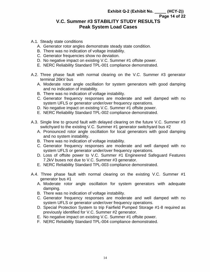
V.C. Summer #3 STABILITY STUDY RESULTS Peak System Load Cases
A.1. Steady state conditions
A. Generator rotor angles demonstrate steady state condition. B. There was no indication of voltage instability. C. Generator frequencies show no deviation. D. No negative impact on existing V.C. Summer #1 offsite power. E. NERC Reliability Standard TPL-001 compliance demonstrated.
A.2. Three phase fault with normal clearing on the V.C. Summer #3 generator
terminal 26kV bus A. Moderate rotor angle oscillation for system generators with good damping
and no indication of instability. B. There was no indication of voltage instability. C. Generator frequency responses are moderate and well damped with no
system UFLS or generator under/over frequency operations. D. No negative impact on existing V.C. Summer #1 offsite power. E. NERC Reliability Standard TPL-002 compliance demonstrated.
A.3. Single line to ground fault with delayed clearing on the future V.C. Summer #3
switchyard to the existing V.C. Summer #1 generator switchyard bus #2 A. Pronounced rotor angle oscillation for local generators with good damping
and no system instability. B. There was no indication of voltage instability. C. Generator frequency responses are moderate and well damped with no
system UFLS or generator under/over frequency operations. D. Loss of offsite power to V.C. Summer #1 Engineered Safeguard Features
7.2kV buses not due to V.C. Summer #3 generator. E. NERC Reliability Standard TPL-003 compliance demonstrated.
A.4. Three phase fault with normal clearing on the existing V.C. Summer #1
generator bus #1 A. Moderate rotor angle oscillation for system generators with adequate
damping. B. There was no indication of voltage instability. C. Generator frequency responses are moderate and well damped with no
system UFLS or generator under/over frequency operations. D. Special Protection System to trip Fairfield Pumped Storage #1-8 required as
previously identified for V.C. Summer #2 generator. E. No negative impact on existing V.C. Summer #1 offsite power. F. NERC Reliability Standard TPL-004 compliance demonstrated.
Exhibit Q-2 (Exhibit No. _____ (HCY-2)) Page 14 of 22
15
V.C. Summer #3 STABILITY STUDY RESULTS System Light Load Cases
A.1. Steady state conditions
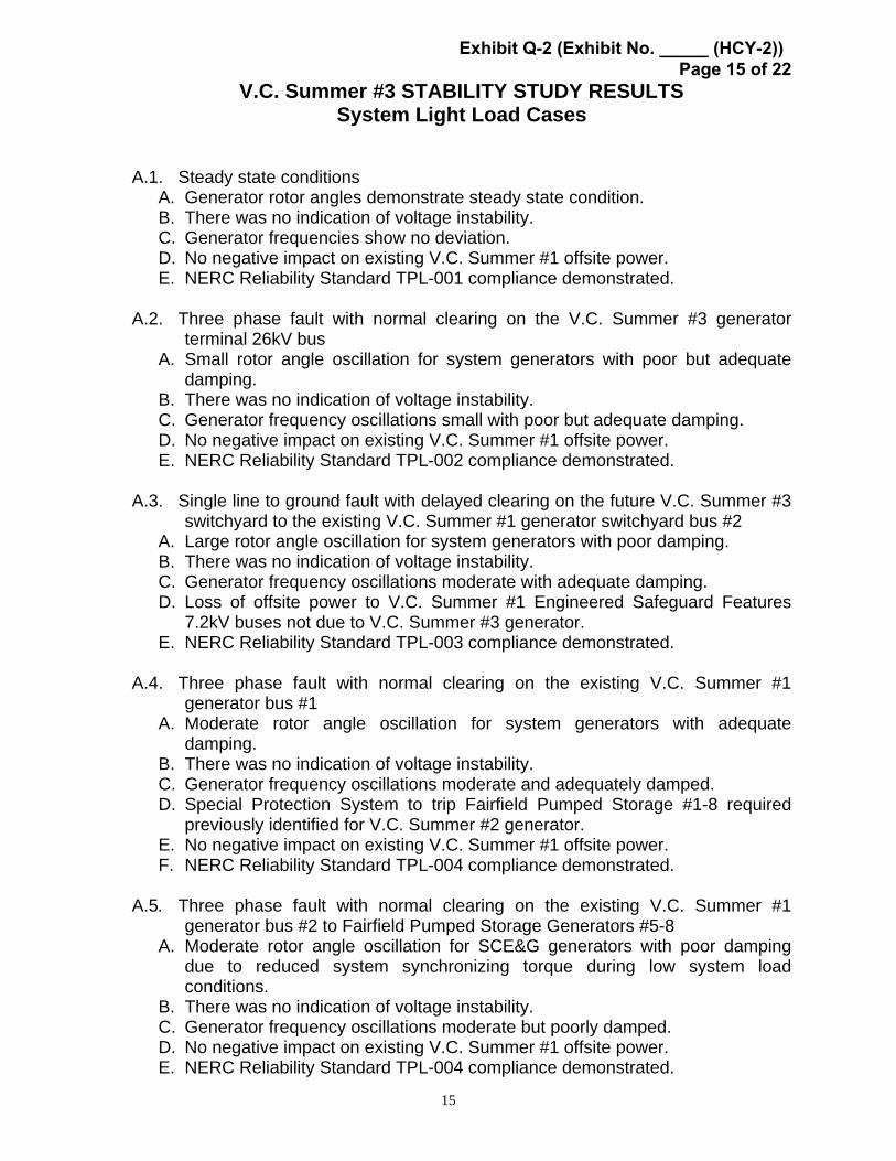
A. Generator rotor angles demonstrate steady state condition. B. There was no indication of voltage instability. C. Generator frequencies show no deviation. D. No negative impact on existing V.C. Summer #1 offsite power. E. NERC Reliability Standard TPL-001 compliance demonstrated.
A.2. Three phase fault with normal clearing on the V.C. Summer #3 generator
terminal 26kV bus A. Small rotor angle oscillation for system generators with poor but adequate
damping. B. There was no indication of voltage instability. C. Generator frequency oscillations small with poor but adequate damping. D. No negative impact on existing V.C. Summer #1 offsite power. E. NERC Reliability Standard TPL-002 compliance demonstrated.
A.3. Single line to ground fault with delayed clearing on the future V.C. Summer #3 switchyard to the existing V.C. Summer #1 generator switchyard bus #2
A. Large rotor angle oscillation for system generators with poor damping. B. There was no indication of voltage instability. C. Generator frequency oscillations moderate with adequate damping. D. Loss of offsite power to V.C. Summer #1 Engineered Safeguard Features
7.2kV buses not due to V.C. Summer #3 generator. E. NERC Reliability Standard TPL-003 compliance demonstrated.
A.4. Three phase fault with normal clearing on the existing V.C. Summer #1
generator bus #1 A. Moderate rotor angle oscillation for system generators with adequate
damping. B. There was no indication of voltage instability. C. Generator frequency oscillations moderate and adequately damped. D. Special Protection System to trip Fairfield Pumped Storage #1-8 required
previously identified for V.C. Summer #2 generator. E. No negative impact on existing V.C. Summer #1 offsite power. F. NERC Reliability Standard TPL-004 compliance demonstrated.
A.5. Three phase fault with normal clearing on the existing V.C. Summer #1
generator bus #2 to Fairfield Pumped Storage Generators #5-8 A. Moderate rotor angle oscillation for SCE&G generators with poor damping
due to reduced system synchronizing torque during low system load conditions.
B. There was no indication of voltage instability. C. Generator frequency oscillations moderate but poorly damped. D. No negative impact on existing V.C. Summer #1 offsite power. E. NERC Reliability Standard TPL-004 compliance demonstrated.
Exhibit Q-2 (Exhibit No. _____ (HCY-2)) Page 15 of 22

16
4. Stability Study Conclusions
This study demonstrates that the proposed V.C. Summer #3 generator interconnection to the SCE&G system is compliant with NERC Reliability Standards. There was no indication of voltage instability. None of the simulations indicated that system UFLS or generator under/overfrequency operations would occur. Neither does the interconnection have a negative impact on the existing V.C. Summer #1 offsite power quality. The cases that resulted in the loss of offsite power for the V.C. Summer #1 generator were caused by delayed clearing relay settings and not by the V.C. Summer #3 generator. Several cases with faults located near the V.C. Summer #1 and the Fairfield Pumped Storage units confirmed the need for a Special Protection System that will trip the Fairfield units to prevent instability. The need for this Special Protection System was identified during the V.C. Summer #2 System Impact Study. The SCE&G Relay and SCADA Applications department has identified the operating features of such a scheme and will make the required system protection improvements.
Exhibit Q-2 (Exhibit No. _____ (HCY-2)) Page 16 of 22

17
III. Required Interconnection Facilities The analyses performed in this study confirmed the results of the Feasibility Study and show that constructing two new 230kV lines from the proposed VC Summer #3 generator to near the Charleston area load center, plus additional transmission improvements described below, are required to reliably transmit SCE&G’s ownership portion of the 1,165 MW of the proposed VC Summer #3 generator from the VC Summer area to the remainder of the SCE&G system. Additionally, the off-peak analysis identified the need for a series reactor on the VC Summer #1-Newport (Duke) 230kV line to limit the power flow on that line. The required transmission improvements:
1. Construct VC Summer New-St George 230kV Double Circuit B1272 line (135 mi) (Add 2 230kV terminals at VC Summer New using breaker-and-a-half design)
2. Construct VC Summer New-VC Summer #1 Bus #1
(Add 230kV terminal at existing VC Summer #1 Bus #1) (Add 230kV terminal at VC Summer New using breaker-and-a-half design)
3. Establish a St George 230kV Substation using breaker-and-a-half design
(6 terminals - 9 breakers) (Future 2 terminals - 3 breakers) (Add land)
4. Fold-in the Canadys-Santee 230kV line at St George 230kV
5. Upgrade the Canadys-St George 230kV line to B1272
(Upgrade Canadys terminal)
6. Fold-in the Wateree-Summerville 230kV line at St George 230kV
7. Upgrade the St George-Summerville 230kV line to B1272 (Upgrade Summerville terminal)
8. Upgrade Saluda-Georgia Pacific 115kV Double Circuit line to 1272
(Upgrade Saluda terminal)
9. Install a 230kV Series Reactor (25% on a 500 MVA base) on the VC Summer #1-Newport (Duke) 230kV line
Add six (6) terminals (8 breakers) to the VC Summer New substation using breaker-and-a-half design.
10. One - for VC Summer #3 generator step up transformer 11. One - for VC Summer #3 station service
Exhibit Q-2 (Exhibit No. _____ (HCY-2)) Page 17 of 22
18
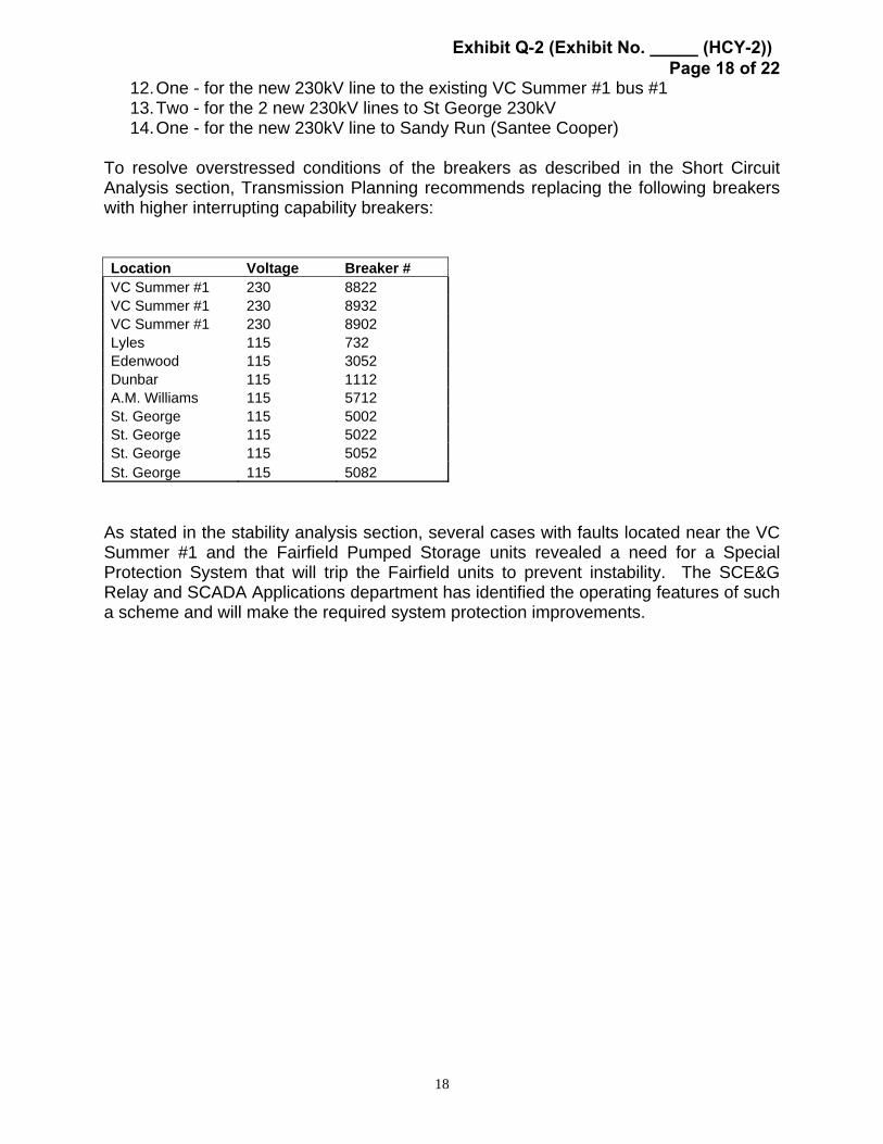
12. One - for the new 230kV line to the existing VC Summer #1 bus #1 13. Two - for the 2 new 230kV lines to St George 230kV 14. One - for the new 230kV line to Sandy Run (Santee Cooper)
To resolve overstressed conditions of the breakers as described in the Short Circuit Analysis section, Transmission Planning recommends replacing the following breakers with higher interrupting capability breakers: Location Voltage Breaker # VC Summer #1 230 8822 VC Summer #1 230 8932 VC Summer #1 230 8902 Lyles 115 732 Edenwood 115 3052 Dunbar 115 1112 A.M. Williams 115 5712 St. George 115 5002 St. George 115 5022 St. George 115 5052 St. George 115 5082
As stated in the stability analysis section, several cases with faults located near the VC Summer #1 and the Fairfield Pumped Storage units revealed a need for a Special Protection System that will trip the Fairfield units to prevent instability. The SCE&G Relay and SCADA Applications department has identified the operating features of such a scheme and will make the required system protection improvements.
Exhibit Q-2 (Exhibit No. _____ (HCY-2)) Page 18 of 22
19
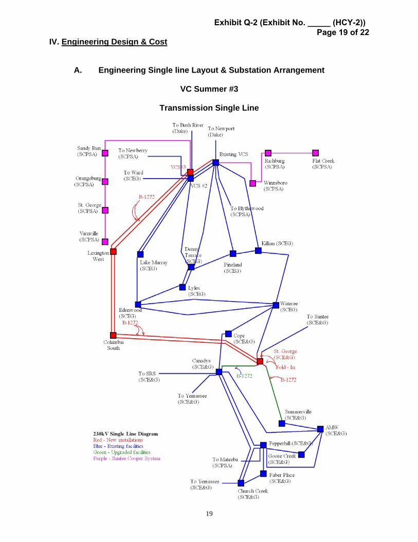
IV. Engineering Design & Cost
A. Engineering Single line Layout & Substation Arrangement
VC Summer #3
Transmission Single Line
Exhibit Q-2 (Exhibit No. _____ (HCY-2)) Page 19 of 22

Faufnld ¹I ¹.¹- N
Nucleal ¹IIVnuabol 0 (Sautcc)
VCSI In» ¹ VCSI bua ¹I
Nnvpn t (Dnke)
¹u
VCSI bee ¹1
ca'IEytbwood (Sautcc)
Dcu n ¹ PuiclalldKdluu
Basil Rnn (Duke)
Nnvb any (8nuce)
'lyn d
Sl Geolgc ttt
St Gcolgc I 1
Sandy Ruu (8atllee)
Lake Munay CD
Reutulg
VCS ¹- )dipl ovculculc
VC8 ¹1 )dipl'ovculculc
Fuua c
Nuclew ¹
Lake Mlu lay ¹I R AT Uba ¹
Douay Tnlace¹l Nut)en IG
RAT (ha ¹1
20
Substation Arrangement
VC Summer #3
Exhibit Q-2 (Exhibit No. _____ (HCY-2)) Page 20 of 22

VCS Late ¹1 tVatteree
VCS Leyte ¹2 Santee
Canadys Sunmrrswitle
Future Funa. e
Existing
Upgrade
New
Funue
21
Substation Arrangement
St George 230kV
Exhibit Q-2 (Exhibit No. _____ (HCY-2)) Page 21 of 22

22
B. Transmission & Substation Cost All cost estimates are in 2006 dollars.
1. Construct VC Summer New-St George 230kV Double Circuit B1272 line (135 miles) .......................................$153,950,000
2. Construct VC Summer New-VC Summer #1 Bus #1)............................$600,000 (Add 230kV terminal at existing VC Summer #1 Bus #1)..............$1,100,000 3. Construct St George 230kV Substation using
breaker-and-a-half design ...........................................................$11,400,000
4. Fold-in the Canadys-Santee 230kV line at St George 230kV.............$1,100,000
5. Upgrade the Canadys-St George 230kV line to B1272 ......................$7,300,000
6. Fold-in the Wateree-Summerville 230kV line at St George 230kV .....$1,100,000
7. Upgrade the St George to Summerville 230kV line to B1272...........$15,300,000
8. Upgrade Saluda-Georgia Pacific 115kV Double Circuit line to 1272 $11,900,000
9. Add six (6) 230kV terminals (8 breakers) at VC Summer New using breaker-and-a-half design ...........................................................$12,000,000
10. Install a 230kV Series Reactor (25% on a 500 MVA base) on the VC Summer #1-Newport (Duke) 230kV line..................................$3,800,000
Replace overstressed breakers
11. Three (3) 230kV breakers ...................................................................$660,000 12. Eight (8) 115kV breakers .................................................................$1,200,000
Total Cost Estimate...................................................................................$221,410,000
Exhibit Q-2 (Exhibit No. _____ (HCY-2)) Page 22 of 22