Embed Size (px)
Citation preview
Generator Condition Monitor (GCM-X) —ATEX
Installation and Operation Manual
GA0456P01 Rev. A
UTILITY SYSTEMS
1 GA0456P01 Rev. A
ContentsGenerator Condition Monitor (GCM-X) ................................................................................................ 5
Safety Consideration ............................................................................................................................... 5
Specifications ........................................................................................................................................... 6
Application ............................................................................................................................................... 7Principle of Operation ........................................................................................................................ 7
System Description .................................................................................................................................. 9System Electronics .............................................................................................................................. 9Control/Display Panel ......................................................................................................................... 9Customer Interface ........................................................................................................................... 10
Installation ............................................................................................................................................. 11Mounting ........................................................................................................................................... 11Lifting ............................................................................................................................................... 11Piping ................................................................................................................................................ 11Electrical Connections ...................................................................................................................... 12Contacts ............................................................................................................................................ 12Signals ............................................................................................................................................... 12Circuit Protection ............................................................................................................................. 13
System Operation .................................................................................................................................. 14GCM-X Initialization ........................................................................................................................ 14
GCM-X Menu Displays ........................................................................................................................ 15Navigating the LCD Display ............................................................................................................ 15LCD Display Menu – Two Modes of Operation ................................................................................ 15Menu Profile ..................................................................................................................................... 15
Menu Navigation Tutorial ..................................................................................................................... 16Activating the Menu ......................................................................................................................... 16Navigating the Menu in Scrolling Mode (GCM-X default) ............................................................... 16Disabling Scrolling Mode .................................................................................................................. 16Navigating the Menu in Non-Scrolling Mode ................................................................................... 16Function (FN) Menu ......................................................................................................................... 17Setup Menu ....................................................................................................................................... 17Test Menu .......................................................................................................................................... 18View Menu ........................................................................................................................................ 18Log Menu .......................................................................................................................................... 19
Procedures ............................................................................................................................................. 20Calibrating the Ion Chamber ........................................................................................................... 20

2GA0456P01 Rev. A
Setting the Sampler Interval ............................................................................................................. 20Setting the Warning Level ................................................................................................................. 20Setting the Low Flow Limit .............................................................................................................. 21Setting the High Flow Limit ............................................................................................................. 21About the Faults Log ........................................................................................................................ 21About the Power Log ........................................................................................................................ 22
Modes of Operation .............................................................................................................................. 23Startup .............................................................................................................................................. 23Startup Problems .............................................................................................................................. 23Suspended Operation ........................................................................................................................ 24Normal Operation ............................................................................................................................. 24
Troubleshooting ..................................................................................................................................... 25
Maintenance .......................................................................................................................................... 29Periodic Maintenance ....................................................................................................................... 29Daily .................................................................................................................................................. 29Weekly ............................................................................................................................................... 29Monthly ............................................................................................................................................. 29Annually ............................................................................................................................................ 29When the Generator is Down ........................................................................................................... 29Tubing and Fitting Replacement ....................................................................................................... 29
Component Replacement Instructions ................................................................................................. 30ICD, Filter Solenoid and Sampling System Solenoid ........................................................................ 30Processor Assembly .......................................................................................................................... 30I/O Assembly (Located in the System Electronics Enclosure) ........................................................... 31Display Assembly .............................................................................................................................. 31Fuses ................................................................................................................................................. 32
GCM-X Remote Panel .......................................................................................................................... 33GCM-X in Local Mode ..................................................................................................................... 33GCM-X in Remote Mode (Optional) ................................................................................................. 33Transferring Control from the GCM-X Remote Panel (Optional) .................................................... 33Removing the GCM-X Remote Panel’s Display Assembly (Optional) .............................................. 33
Appendix A ............................................................................................................................................. 46Generator Condition Monitor Output Traces ................................................................................... 46
GCM-X - Parts List ............................................................................................................................... 34
3 GA0456P01 Rev. A
FiguresTable 1 - Customer Contacts ................................................................................................................................. 25Table 2 - Display Indicators ................................................................................................................................... 26Table 3 - Display Keys .......................................................................................................................................... 27Table 4 - GCM-X Status ........................................................................................................................................ 28Table 5 - Relay Problems ...................................................................................................................................... 28Figure 1 - System Overview .................................................................................................................................. 35Figure 2 - Piping Schematic ................................................................................................................................... 36Figure 3 - GCM-X Outline ..................................................................................................................................... 37Figure 4 - Customer Interface Wiring .................................................................................................................... 39Figure 5 - ICD Current and Flow .......................................................................................................................... 40Figure 6 - GCM-X Remote Panel (Optional) ........................................................................................................ 41Figure A1 - Front View, GCM-X ........................................................................................................................... 42Figure A2 - Back View, GCM-X ........................................................................................................................... 43Figure A3 - GCM-X Display, Front View .............................................................................................................. 44Figure A4 - GCM-X Display - Backside of Door, “Cold Start” Button Access .................................................... 45

4GA0456P01 Rev. A
5 GA0456P01 Rev. A
GENERATOR CONDITION MONITOR (GCM-X)IMPORTANT INFORMATION!
THIS EQUIPMENT OPERATES AT VOLTAGE LEVELS THAT CAN BE HAZARDOUS TO PERSONNEL.THE SECTION ABOUT SAFETY CONSIDERATIONS SHOULD BE READ BEFORE INSTALLING ORSERVICING.
THESE INSTRUCTIONS DO NOT PURPORT TO COVER ALL DETAILS OR VARIATIONS INEQUIPMENT NOR TO PROVIDE FOR EVERY POSSIBLE CONTINGENCY TO BE MET INCONNECTION WITH INSTALLATION, OPERATION OR MAINTENANCE.
SHOULD FURTHER INFORMATION BE DESIRED, OR SHOULD PARTICULAR PROBLEMS ARISETHAT ARE NOT COVERED SUFFICIENTLY FOR THE PURCHASER’S PURPOSES, THE MATTERSHOULD BE REFERRED TO ENVIRONMENT ONE CORPORATION.
GENERATOR CONDITION MONITOR (GCM-X)SAFETY CONSIDERATION
THE SYSTEM ELECTRONICS ENCLOSURE, CUSTOMER INTERFACE ENCLOSURE, SOLENOIDVALVES AND HEATER CONTAIN 115 AND/OR 230 VOLTS AC. THIS VOLTAGE APPEARS AT THE ACPOWER STRIP AND VARIOUS OTHER POINTS. EQUIPMENT OPERATION INVOLVES AFLAMMABLE GAS (HYDROGEN) UNDER PRESSURE. APPROPRIATE MEASURES MUST BETAKEN TO PREVENT LEAKS AND AVOID SOURCES OF IGNITION.
ALL ELECTRICAL CONNECTIONS TO THE SYSTEM ELECTRONICS, CUSTOMER INTERFACE ANDCONTROL/DISPLAY PANEL SHOULD BE TESTED AND VERIFIED TO BE CORRECT.
ALL WIRING MUST BE IN ACCORDANCE WITH CENELEC STANDARD EN50014.
USE OF THIS EQUIPMENT IN A MANNER NOT SPECIFIED BY ENVIRONMENT ONE CORPORATIONIS STRICTLY PROHIBITED.
IT IS NECESSARY TO ENSURE THAT ALL SEALING FITTINGS ARE FILLED WITH AN APPROVEDCOMPOUND. THIS IS A CENELEC REQUIREMENT FOR ZONE 2, GROUP II H2 ENVIRONMENTS.
ALL GAS CONNECTIONS TO THE GCM-X MUST BE LEAK CHECKED PRIOR TO APPLYING ACPOWER.
CHECK FOR LEAKS AT ALL TUBING AND MECHANICAL CONNECTIONS INSIDE THE GCM-XENCLOSURE. IF LEAKS ARE FOUND, DETERMINE THE CAUSE AND REPAIR. REPEATING THELEAK CHECK UNTIL THE GCM-X ENCLOSURE IS DETERMINED TO BE LEAK TIGHT ISNECESSARY.

6GA0456P01 Rev. A
Specifications
Measurement Characteristics
Detection principle Ionization chamber
Hydrogen Flow Rate Adjusted by internal valve
Differential Pressure 4” to 5” (102 mm to 127 mm) min.
Readout (bar graph)
Normal Operation 80% of scale, typicalAlarm Condition 50% of scale, typicalFlow 1.5
Electrical Characteristics
PowerInput Voltage 85 VAC to 250 VACInput Frequency 47 Hz to 63 HzInput Power 100WInrush Current 2A
Outputs, Relays
Contact Rating 5A @ 250 VAC ResistiveAlarmWarning 5A @ 30 VDC ResistiveTrouble 100 mA @ 125 VDC Resistive
Outputs, Signal (Caution: Do not externally excite output signals)
Output 4-20 mA current output (transmitter)4-20 mA = 0-100%
Flow 4-20 mA current output (transmitter)4-20 mA = 0-3” H2O
Mechanical Characteristics
Dimensions, overall 30.8” H x 21.8” W x 23.6” D(782mm x 553mm x 600mm)
Temperature 32-125 F (0-52 C)
Area Classification Zone 2, Ex II H2, CE
Hydrogen Pressure 100 psi maximum
Connections, gas inlet 150 lb., ½” pipe flanges, standard

7 GA0456P01 Rev. A
Application
The Generator Condition Monitor (GCM) is a sensitive real-time instrument designed to provideimmediate indication of overheating in hydrogen-cooled generators before extensive damage canoccur. Tests conducted on operating hydrogen-cooled generators have shown that the GCM candetect thermal decomposition of small amounts of insulating materials.
Thermal decomposition of organic materials such as epoxy paint, core lamination enamel orother insulating materials used in the generator results in the production of a large number ofsmall particles. The onset of particle production, as the material is heated, occurs at a tempera-ture characteristic of the material and its surrounding atmosphere. Below this temperature, noparticles are created, yet once the critical temperature is reached, millions of submicron par-ticles are generated each second for every square centimeter of surface.
GCM-X represents the next generation in condition monitoring — incorporating microprocessor-based electronics, flameproof, intrinsically safe design features (Ex II H2, CE) and self diagnos-tics. E/One has taken the field-proven system that has served the worldwide power generationcommunity for decades and improved upon it in the form of increased safety, performance andreliability.
GCM-X features:
· Microprocessor-based electronics
· Flameproof, intrinsically safe design (Ex II H2, CE)
· Self diagnostics
· Flow indication
· Trouble indication
· Separate enclosure for system electronics and customer interface
· Allowance for remote control/display and communication
· Integral auto/manual sampling system
· Automatic alarm verification
· Simple installation
· Maintenance-free operation
Principle of Operation
A basic understanding of the GCM is necessary in order to properly utilize the information itprovides.
Particle detection occurs by means of an ionization chamber through which the hydrogen cool-ing gas is continuously circulated by the pressure produced by the generator fan. The Ion Cham-ber Detector (ICD) consists of an ionizing section and ion collecting chamber contained in a

8GA0456P01 Rev. A
pressure housing. The hydrogen first passes through the ionizing section, which contains a lowlevel alpha source (Thorium 232). The resulting ions then pass with the hydrogen to the ioncollecting chamber in which there is an electrode maintained at -10 VDC. Because the ions areextremely small, they have a high ratio of charge to mass, giving them a high mobility whenplaced in an electric field. The -10 VDC potential is sufficient to cause most of the ions to beattracted to a collecting electrode, where they produce the output current.
High concentrations of submicron particles (pyrolysis products) are produced whenever anymaterial within the generator is heated sufficiently to produce thermal decomposition. These “hotspots” can lead to catastrophic failure if not caught in time.
When particles are present in the hydrogen, some of the ions will become attached to them.Therefore, the charge to mass ratio of the particle-ion combination is very much reduced (by afactor of a thousand or so), and the mobility is very low. This means that only a very few are nowattracted to the collecting electrode, resulting in a reduced output current.
Upon detection, the microprocessor initiates and monitors an alarm verification sequence. If thealarm is confirmed, a verified alarm indication is given, alarm contacts are switched and aportion of the hydrogen flow automatically passes through the sampling system where theseparticles are collected for laboratory analysis. The sampling system can be set to auto ormanual.
Alarm confirmation is made quickly by the automatic alarm verification circuit that activates thesolenoid valve in the filter/solenoid valve assembly. Normally bypassed, all the hydrogen thenpasses through the filter, which removes the particles. If the alarm is valid and thermally pro-duced particles are present, their removal in this manner will cause the collector current to returnto its normal level, confirming their presence and overheating.
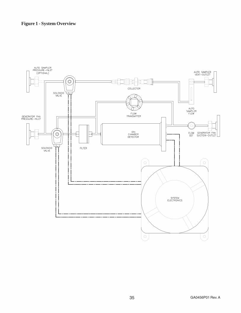
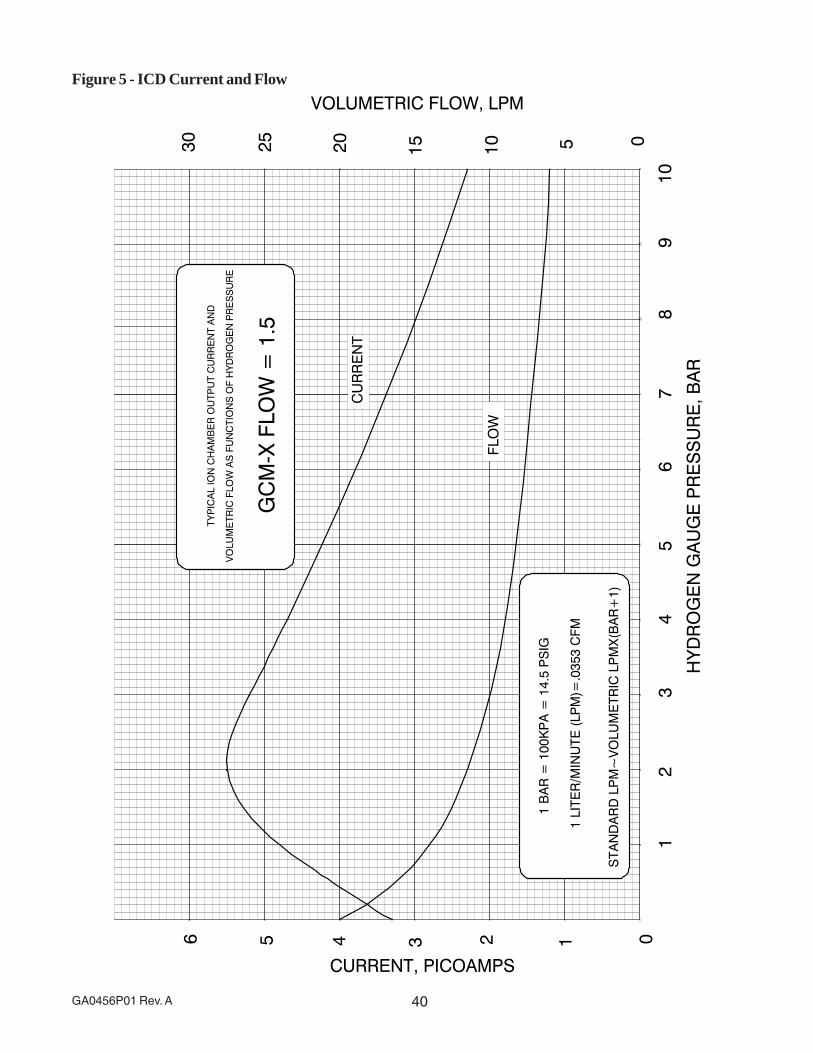
Figure 1 shows a typical GCM. In this arrangement a differential pressure transmitter that moni-tors the pressure drop across the ion chamber indicates flow.
Ion chamber output current is amplified by an electrometer. The amplified current and flow aredisplayed on bar graphs. The usual operating procedure is to adjust the flow to a given differen-tial pressure indication and calibrate the electrometer gain to produce an output of 80 percent.Refer to Appendix A, Generator Condition Monitor Output Traces.
(Principle of Operation cont’d)

9 GA0456P01 Rev. A
System Description
The GCM-X is designed for use on hydrogen-cooled generators. It is designed to operate in Zone1, IIC hazardous areas (Zone 2, Group II H2). GCM-X’s main purpose is to detect overheating inhydrogen cooled generators.
The major components of the GCM-X include the System Electronics, Control/Display Panel,Customer Interface, Ion Chamber Detector (ICD) and Transmitter (Figures A1, A2 and A3).
System Electronics
The System Electronics consist of one Processor Board, one Input/Output Board, one PowerSupply, one RFI filter and three Isolation Barriers (Figure A1). All are mounted in a flameproofenclosure. Electrical connections are made through three cable glands (optional conduit seal-ers).
The System Electronics provide calibration, mode selection, alarm contacts, data logging,system inputs/outputs and diagnostics.
Fail-safe operation of the GCM-X is assured by:
1. On power-up the GCM-X must execute and pass qualifying self tests. Failure in any testresults in the termination of operation and the annunciation of the condition causing thefailure.
2. Following power-up and/or system reset, the GCM-X is continuously supervised by anindependent watchdog monitor that serves to reset it should its operation become erratic.
3. The GCM-X is completely self-supervised and continuously checks itself for legal processorfunctioning, internal voltages, analog-to-digital conversion accuracy, integrity of cabling andrelay operation. Any faults are immediately annunciated.
Control/Display Panel
The Control/Display Panel provides control of all functions of the GCM-X as well as completeannunciation of GCM-X’s status (Figure A3). Functions are accessed by means of a four-buttonmembrane-switch keypad and 16-character Liquid Crystal Display (LCD). Generally, pressingthe Fn (Function) key causes the LCD to continuously scroll the names of the available func-tions. A function may then be accessed by pressing the Enter key when the function nameappears. See Menu Navigation Tutorial for more information.
After the GCM-X has been installed and commissioned, individuals performing servicework on the Display Panel must wear an electrostatic wriststrap.
The Display Panel provides Light Emitting Diodes (LED’s) to annunciate GCM-X status; theyindicate Warning, Alarm and Trouble conditions. In addition, they display Sampler and Resetmode, and the status of the sampler and verification filter. A green LED indicates AC Power.
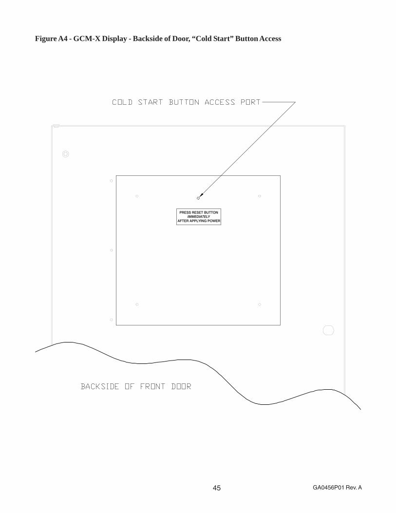
To permit a system level initialization (“cold start”) a momentary push-button — located behindthe Display Panel (at the upper edge of the board) — may be pressed. Since all calibrationconstants are stored in non-volatile memory, these values will not be lost should the system beinitialized or should it lose, then regain, AC power.
10GA0456P01 Rev. A
The “cold start” button should be pressed via a nonconductive tool. Depending on the GCM-Xconfiguration, the “Cold Start” button may be accessed by reaching behind the Display Assemblyfrom the front, or by way of a small access hole located on the back side of the GCM-X frontdoor (Figure A3).
Customer Interface
The Customer Interface/System Electronics enclosure contains one RFI filter and circuit boardassemblies (Figure A1). The I/O circuit board assembly has terminal strips where all customerconnections (relay outputs, signal output and power) are made. Electrical connections are madethrough three cable glands (optional conduit sealers) provided at the side of the enclosure.
(Control/Display Panel cont’d)

11 GA0456P01 Rev. A
Installation
These instructions provide details to facilitate the equipment installation. The exact location of theGenerator Condition Monitor, Explosion-Proof Design (GCM-X) should be in accordance withrecommendations made by the generator manufacturer or its authorized representative.
Prior to applying power to the GCM-X System, ensure that the local power source used matchesthe power rating on the GCM-X nameplate.
All Gas lines must be connected to the GCM-X and leak tested before continuing.
CAUTION! Care must be taken when opening the covers on the flameproof enclosure to avoiddamage (scratches, etc.) to the sealing surfaces of the cover and enclosure. Do not remove thecover from the enclosure unless power is removed from the System Electronics and the systemis free of hydrogen. Individuals involved in opening the flameproof enclosure covers must betrained in the use of such equipment and should adhere to ATEX, Cenelec or NEC standards,local codes and generally accepted professional practices.
Mounting
The GCM-X should be installed indoors, or at least under a roof that extends far enough toprotect it from the elements. If outdoor installation is necessary, a protective enclosure must beused, located out of direct sunlight to prevent the interior ambient temperature from exceeding 52C (125 F). The protective enclosure should also be ventilated to prevent the accumulation ofhydrogen in the event of a leak.
Lifting
The GCM-X should be lifted from the bottom of the cabinet whenever possible. It should never belifted from the flanges.
If the unit is being lifted without the assistance of a mechanical lift, the upper portion of thecabinet is recessed, allowing for a manual grip (Figure 3). In any and all instances, the cabinetshould be supported to prevent tipping.
Piping
Figure 2 shows the locations of gas connections. The cabinet should be located close to thegenerator so that the inlet gas line will be 30 meters (100 feet) or shorter in order to minimizeloss of signal. The ambient temperature should not exceed 52 C (125 F). Gas dryers, or otherdevices that would filter out particles, should not be installed in series in the signal line ahead ofthe GCM-X (Figure 2).
The gas connections are standard pipe flanges modified to use O-rings. The outlet and inletconnections at the generator must be located so as to produce adequate pressure differential inorder to provide sufficient flow (DP of 4” to 5” min.). If a dryer is connected in parallel with theGCM-X, its effect on the pressure drops in the piping should be checked so that flow changesthrough the dryer (as when it is being reactivated) will not adversely affect the flow through theGCM-X. Care should be taken also in location of the generator outlet connection so that thehydrogen stream will not be contaminated by oil vapor from the bearings. The high and lowpressure taps preferably should be located as high as possible on the generator casing in orderto prevent the entry of liquids into the lines. Generators with two fans should have an outlet tap at
12GA0456P01 Rev. A
each end connected to a manifold so a composite hydrogen sample is supplied to the GCM-X.
To prevent the accumulation of liquids in the lines, horizontal runs should slope down in thedirection of flow, with a drip leg installed at all low points. At each drip leg the succeeding lengthof pipe should start with a vertical tap at the top of the preceding section. This applies also to thelines from the GCM-X back to the generator, to prevent liquids from draining back to the GCM-X,particularly after shutdown. It is recommended that an oil moisture trap, such as EnvironmentOne Part No. GA0174P02, with grounding kit GB0084G02, be installed at the inlet of the GCM-X(Figure 2).
CAUTION: SOME OIL-MOISTURE TRAPS CAN REMOVE THE OVERHEATING PARTICU-LATE SENSED BY THE GCM-X. CONSULT ENVIRONMENT ONE BEFORE USING ANYTRAP OTHER THAN THAT SUPPLIED BY ENVIRONMENT ONE.
A line must be connected to the vent outlet at the right side of the cabinet (Figure 2). This lineshould not contain valves, and must provide low restriction to the flow of hydrogen so that it canbe safely vented to atmospheric pressure.
Electrical Connections
Electrical connections are made through three male conduit unions provided at the back of theGCM-X cabinet (Figures 3 and A2). System power requirement is 115/230 VAC, 50/60 Hz. Thesource of AC power should be reliable and not subject to severe transients.
To gain access to the inside of the System Electronics enclosure for electrical connections,remove the threaded cover. Take care that the threads of the enclosure are not damaged duringthe removal process.
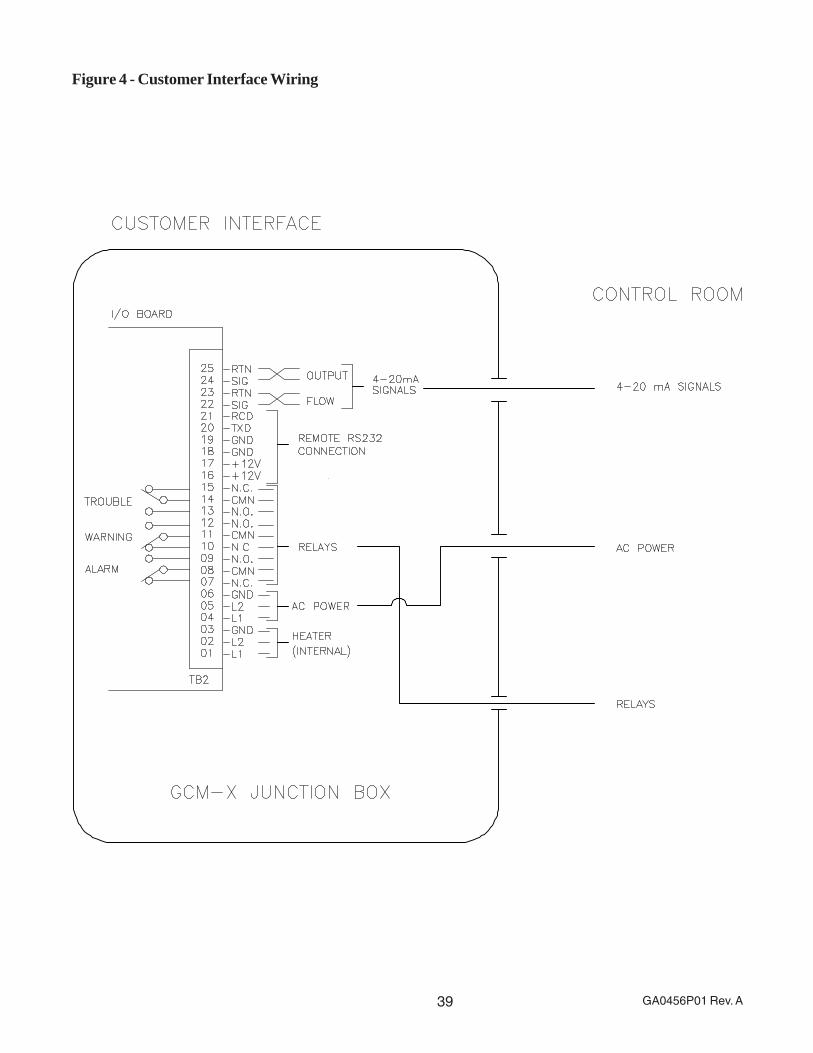
Wiring and wire routing should be in accordance with Figure 4 so that noise generated from theAC power and contacts does not interfere with the signals. If a circuit breaker is used, it shouldbe 10 amps. The ground wire should be 12 AWG with 25-amp capacity.
ALL WIRING MUST BE IN ACCORDANCE WITH CENELEC STANDARD EN50014.
Contacts
As shown in Figure 4, the GCM-X provides these relay contacts:
· Warning Relay Both a normally open and a normally closed contact (single pole, doublethrow configuration) is provided and a warning is signaled by an energized relay.
· Alarm Relay Both a normally open and a normally closed contact (single pole, double throwconfiguration) is provided and an alarm is signaled by an energized relay.
· Trouble Relay Both a normally open and a normally closed contact (single pole, doublethrow configuration) is provided and Trouble is signaled by a de-energized relay.
Signals
· Output Signal 4-20 mA signal (transmitter)
· Flow 4-20 mA signal (transmitter)
The 4-20 mA signals are self-powered. Do NOT excite the 4-20 mA signals.
(Piping cont’d)

13 GA0456P01 Rev. A
Circuit Protection
The 2-amp slo-blo fuse (F1) provides circuit protection for 115/230 VAC.
14GA0456P01 Rev. A
System Operation
GCM-X Initialization
With system power on, press the RESET push-button on the backside of the DISPLAY PANEL(Figure A3). The GCM-X DISPLAY PANEL will respond with (a) all discrete LED’s lit; (b) allsegments of the FLOWSET and OUTPUT bar graphs lit; and (c) all pixels of the LCD display on.
Once communication has been established with the rest of the system, (a) all discrete LED’s,except the AC POWER, LOCAL, GCM FAULT and FLOW LED’s, will turn off; (b) all segments ofthe FLOWSET and OUTPUT displays will turn off; and (c) the display will echo the results ofcold start initialization:
· GCM-X Ver 2.0E-7
· CHECKSUM OK
· POWER OK
· RELAY TEST …
· … PASSED
· ICD=N.NpA
· DP=N.N INCHES
NORMAL OPERATION will flash for two seconds; the GCM-X will begin normal operation and thedisplay will read “GCM-X by E/One.”
For a first-time installation, it is essential that a calibration be performed on the GCM-X system;also, the faults log should be cleared. See CALIBRATION under the SETUP MENU and CLEARFAULTS LOG under LOG MENU for specific instructions.
15 GA0456P01 Rev. A
GCM-X Menu Displays
The following sections provide definitions and user information regarding the various menus thatare accessible via the GCM-X’s LCD display. It is strongly recommended that users familiarizethemselves with this section. Additional questions can be forwarded to Environment One.
Navigating the LCD Display
Four keys are used to control menu operation. The keys are FN, ENTER, UP ARROW andDOWN ARROW.
· The FN key activates the menu and exits the menu.
· The ENTER key selects an item from the menu.
The UP ARROW and DOWN ARROW keys change the selection displayed.
LCD Display Menu – Two Modes of Operation
The menu has two modes of operation. The modes are scrolling and non-scrolling.
· In scrolling mode the selection shown on the LCD changes automatically every two seconds.
· In non-scrolling mode the UP ARROW and DOWN ARROW keys must be used to changethe selection.
Scrolling is the default mode. Users can change modes by reviewing the SETUP MENU sectionin the following pages.
Menu Profile
Five menus are available: they are the Function menu, the Log menu, the Setup menu, the Viewmenu and the Test menu. The Function menu is the top-level menu; all of the other menus areaccessed through this menu.
Function
· Log
· Setup
· View
· Test

16GA0456P01 Rev. A
Menu Navigation Tutorial
Activating the Menu
· Press FN to start the menu. The LCD should display the prompt <FUNCTION MENU>.
· Press FN again to turn it off.
Navigating the Menu in Scrolling Mode (GCM-X default)
· Press FN to start the menu. The LCD should display the prompt <FUNCTION MENU>. Aftertwo seconds the prompt should change to GO REMOTE.
· Wait until the prompt is GO TO VIEW MENU and press the ENTER key.
· The LCD should display the prompt <VIEW MENU>.
· Wait until the prompt is SHOW ICD CURRENT and press the ENTER key. The displayshould show ICD=N.NpA where N.N is the present value of the ICD current. Press the FNkey. The prompt will be restored to SHOW ICD CURRENT.
· Press FN again. The prompt will be restored to GO TO VIEW MENU.
· Press FN a third time. The LCD will display “GCM-X by E/One” as the menu is deactivated.
Disabling Scrolling Mode
· Press FN to start the menu.
· Wait until the prompt is GO TO SETUP MENU and press ENTER.
· Wait until the prompt is SET SCROLL OFF and press ENTER.
· The prompt will flash SET SCROLL OFF.
· Press FN to return to the beginning of the menu.
Navigating the Menu in Non-Scrolling Mode
· The LCD should display the prompt <FUNCTION MENU>. Press the DOWN ARROW keyuntil the prompt is GO TO VIEW MENU and press the ENTER key.
· The LCD should display the prompt <VIEW MENU>. Press the DOWN ARROW key until theprompt is SHOW ICD CURRENT and press the ENTER key. The display should showICD=N.NpA where N.N is the present value of the ICD current.
· Press the FN key. The prompt will be restored to SHOW ICD CURRENT.
· Press FN again. The prompt will be restored to GO TO VIEW MENU.
· Press FN a third time. The LCD will display “GCM-X by E/One.”

17 GA0456P01 Rev. A
Function (FN) Menu
· GO REMOTE Select this item to transfer control to the optional, remotely located displaypanel. The GO REMOTE prompt will flash for two seconds after it is selected. If the FN key ispressed while GO REMOTE is still flashing, transfer will be canceled. If the GCM-X cannotdetect a remote panel, the transfer will be canceled and the GCM-X will remain in local mode.
· GO LOCAL Select this item to transfer control to the display panel located on the front of theGCM-X cabinet (only if the optional GCM-X Remote Panel installed). The GO LOCAL promptwill flash for two seconds after it is selected. If the FN key is pressed while GO LOCAL is stillflashing, transfer will be canceled.
· GO TO LOG MENU Select this item to enter the LOG MENU. The log menu containsselections to view and clear the fault and power logs. The log menu also includes a selectionto view the software version number.
· GO TO SETUP MENU Select this item to enter the SETUP MENU. The setup menu in-cludes selections for calibration and configuration. Items that can be configured include thesampler interval, the operating mode and the menu scroll rate. The setup menu also includesa selection to calibrate the ion chamber detector.
· GO TO TEST MENU Select this item to enter the TEST MENU. The test menu containsselections to test the power supplies, the keypad, the relays, the solenoids, the bar graphsand the four- to 20-milliamp (4-20 mA) outputs.
· GO TO VIEW MENU Select this item to enter the VIEW MENU. The view menu containsselections to view the ion chamber electrical output, the differential pressure across the ionchamber and the four software variables associated with the ion chamber amplifier.
Setup Menu
· CALIBRATION Select this item to calibrate the ion chamber output. When selected theCALIBRATION prompt will flash for two seconds before entering the calibration procedure. Ifthe FN key is pressed while it is still flashing the procedure will be canceled. See Calibratingthe Ion Chamber for more information.
· SAMPLER INTERVAL Select this item to change the sampler interval. See Setting theSampler Interval for more information.
· WARNING LEVEL Select this item to change the warning level. See Setting the WarningLevel for more information.
· LOW FLOW LIMIT Select this item to change the low flow limit. See Setting the Low FlowLimit for more information.
· HIGH FLOW LIMIT Select this item to change the high flow limit. See Setting the High FlowLimit for more information.
· STOP MONITORING This item is to be used for troubleshooting and is displayed when themonitoring is currently turned on. Select it to turn monitoring off. When selected the STOPMONITORING prompt will flash STOPPING for two seconds before monitoring is suspended.If the FN key is pressed while it is still flashing, the command will be canceled. See Sus-pended Operation for more information.
18GA0456P01 Rev. A
· START MONITORING This item is displayed when the monitoring is currently turned off.Select it to turn monitoring on. When selected the START MONITORING prompt will flashSTARTING for two seconds before monitoring begins. If the FN key is pressed while it is stillflashing, the command will be canceled. See Normal Operation for more information.
· SET SCROLL OFF This item is displayed when the scrolling is currently turned on. Select itto turn scrolling off. When scrolling is inactive the displayed menu items will not change untila menu key (UP ARROW, DOWN ARROW, FN or ENTER) is pressed.
· SET SCROLL ON This item is displayed when the scrolling is currently turned off. Select itto turn scrolling on. When scrolling is active, the displayed menu items will change onceevery two seconds.
Test Menu
· CONTACT TEST Select this item to start an interactive test of the relay contacts. The GCM-X will place all relays except one in a de-energized condition. The LCD will display the nameof the single relay that is still energized. Use the arrow keys to change which relay is ener-gized. Press the FN or ENTER keys to terminate the test.
· KEYPAD TEST Select this item to start an interactive test of the keypad. The LCD willdisplay the prompt PRESS ANY KEY at the start of the test. Test the keypad by pressing, oneat a time, all of the keys on the keypad, reserving the FN key for last. The LCD will echo thename of each key as it is pressed. The test will terminate when the FN key is pressed.
· OUTPUT TEST Select this item to start an interactive test of the bar graphs and four- to 20-milliamp (4-20 mA) outputs. The GCM-X will clear the bar graphs, set the four- to 20-milliampoutputs to four milliamps and display CURRENT=4mA on the LCD display at the start of thetest. Use the arrow keys to increase or decrease the current in one milliamp steps. The bargraphs will track the current outputs with four milliamps equal to zero percent and 20milliamps equal to 100 percent. Press FN or ENTER to terminate the test.
· POWER TEST Select this item to test the power supplies. When POWER TEST is se-lected, the GCM-X will display the voltage for each power supply in the format <nominalvalue>=<present value>. An example for the 12-volt power supply would be +12 VOLTS=12.1. The GCM-X will scroll through all five power supply voltages. The voltages are dis-played for two seconds apiece.
· RELAY TEST Select this item to test all of the relays. The LCD will display RELAYTEST … The system will cause each relay to be energized. If no errors are detected, theLCD will display RELAYS PASS. If an error is detected, the LCD will display the failure modeand then list the names of the malfunctioning relays. The failure modes are STUCK ON,STUCK OFF and NOT TESTED. Refer to Table 5 for a list of the probable cause(s) of theseerrors.
View Menu
· SHOW ICD CURRENT Select this item to display the ICD’s electrical output in pico amps.
· SHOW DP INCHES Select this item to display the differential pressure across the ionchamber in inches of water.
· SHOW AMPLIFIER Select this item to view the four software variables associated with the
(Setup Menu cont’d)
19 GA0456P01 Rev. A
ion chamber amplifier. The variables are displayed as four pairs of hexadecimal digits. This isan advanced diagnostic intended for factory use only.
Log Menu
· SHOW FAULTS LOG Select this item to view the faults log. See About the Fault Log formore information.
· CLEAR FAULTS LOG Select this item to clear the faults log. When selected the CLEARFAULTS LOG prompt will flash for two seconds before clearing the faults log. If the FN key ispressed while it is still flashing clearing of the log will be canceled. See About the Fault Logfor more information.
· SHOW POWER LOG Select this item to view the power log. See About the Power Log formore information.
· CLEAR POWER LOG Select this item to clear the power log. When selected the CLEARPOWER LOG prompt will flash for two seconds before clearing the power log. If the FN keyis pressed while it is still flashing clearing of the log will be canceled. See About the PowerLog for more information.
· SHOW PROGRAM ID Select this item to display the program identification and revision levelin the format GCM-X Rev X.X. This manual was written for software version 2.0E-20.
(View Menu cont’d)
20GA0456P01 Rev. A
Procedures
Calibrating the Ion Chamber
· Alarms and warnings are detected by comparing the electrical output of the ion chamberdetector against a reference level. The calibration process sets this reference level.
· The calibration procedure takes about 25 seconds to run. Once started the calibrationprocedure can be canceled by pressing the FN key.
· The GCM-X requires that the differential pressure across the ion chamber detector bebetween 1.4 and 1.6 inches of water during the calibration procedure. The GCM-X will haltcalibration and prompt the operator to adjust the FLOWSET valve if the pressure is outsideof this range. Calibration will resume when the differential pressure enters the required rangeand remains there for at least five seconds. If insufficient differential pressure is available tomeet this requirement it can be bypassed by pressing the FN key. However, operating theGCM-X with insufficient differential pressure will reduce response time.
· The GCM-X engages the verification filter to remove any particulate from the gas streamduring the calibration process. It waits at least 15 seconds for the filtered gas to flush anyparticulate out of the ion chamber. It considers the ion chamber flushed when its outputcurrent varies by less than ±4 percent over a five-second period. If the output current is notstable at the end of the 15-second waiting period the GCM-X will wait until it becomes stable.
· The GCM-X displays the output as a percentage of the initial reference level at the end of theinitial 15-second waiting period. Once the output stabilizes, the GCM-X calculates a newvalue for the reference level and displays the output as a percentage of this new referencelevel.
· The new reference level will be 1.25 times the average electrical output level of the ionchamber detector during the last five seconds of the calibration procedure.
Setting the Sampler Interval
· The sampler interval is the length of time that the GCM-X routes hydrogen through thecollector in response to a verified alarm or the operator pressing the SAMPLER START/STOP key. The sampler interval can be changed by selecting SAMPLER INTERVAL from theSETUP MENU.
· When SAMPLER INTERVAL is selected the sampler interval will be displayed on the LCDdisplay. Press the UP ARROW key to increase it. Press the DOWN ARROW key to de-crease it. It cannot be increased beyond 30 minutes or decreased below 10 minutes.
· Press the ENTER key to save your changes and return to the SETUP MENU. Press the FNkey to discard the changes and return to the SETUP MENU.
Setting the Warning Level
· The warning level determines what electrical output from the ion chamber detector will triggera WARNING indication The warning level is expressed as a percentage of the reference levelset by the calibration procedure. A WARNING indication is given when the ratio of the electri-cal output to the reference level is less than the value of warning level. The factory default
21 GA0456P01 Rev. A
value for the warning level is 70 percent. The warning level can be changed by selectingWARNING LEVEL from the SETUP MENU.
· When WARNING LEVEL is selected, the warning level will be displayed on the LCD display.Press the UP ARROW key to increase it. Press the DOWN ARROW key to decrease it. Itcannot be increased beyond 80 percent or decreased below 50 percent. Press the ENTERkey to save your changes and return to the SETUP MENU. Press the FN key to discard thechanges and return to the SETUP MENU.
Setting the Low Flow Limit
· The low flow limit determines what differential pressure, across the ion chamber detector, willcause a FLOW TROUBLE indication. The low flow limit is expressed in inches of water. AFLOW TROUBLE indication is given when the differential pressure drops below the low flowlimit. The factory default value for the low flow limit is 1.1 inches of water. The low flow limitcan be changed by selecting LOW FLOW LIMIT from the SETUP MENU.
· When LOW FLOW LIMIT is selected the low flow limit will be displayed on the LCD display.Press the UP ARROW key to increase it. Press the DOWN ARROW key to decrease it. Itcannot be increased beyond 2.5 inches of water or decreased below 0.5 inches of water.Press the ENTER key to save your changes and return to the SETUP MENU. Press the FNkey to discard the changes and return to the SETUP MENU.
Setting the High Flow Limit
· The high flow limit determines what differential pressure, across the ion chamber detector,will cause a FLOW TROUBLE indication. The high flow limit is expressed in inches of water.A FLOW TROUBLE indication is given when the differential pressure rises above the highflow limit. The factory default value for the high flow limit is 1.9 inches of water.
· The high flow limit can be changed by selecting HIGH FLOW LIMIT from the SETUP MENU.
· When HIGH FLOW LIMIT is selected the high flow limit will be displayed on the LCD display.Press the UP ARROW key to increase it and press the DOWN ARROW key to decrease it.It cannot be increased beyond 2.5 inches of water or decreased below 0.5 inches of water.Press the ENTER key to save your changes and return to the SETUP MENU. Press the FNkey to discard the changes and return to the SETUP MENU.
About the Faults Log
· The Faults log traps these error conditions: I/O Read Error, I/O Write Error, Unverified Alarm,Flow Fault and Power Fault.
· An I/O Read Error is logged when a read error is detected in the communication channel thatconnects the processor and I/O board.
· An I/O Write Error is logged when a write error is detected in the communication channel thatconnects the processor and I/O board.
· An Unverified Alarm is logged when the GCM-X starts an alarm verification sequence butcannot verify the alarm.
· A Flow Fault is logged when the differential pressure across the ion chamber detector fallsbelow the low flow limit or climbs above the high flow limit.
(Warning Level cont’d)
22GA0456P01 Rev. A
· A Power Fault is logged when the measured voltage of one or more of the power supplies isout of specification.
About the Power Log
· The Power log records the minimum and maximum voltage of each power supply. Thevoltage is sampled once every two seconds.
· When SHOW POWER LOG is selected, the GCM-X will display the minimum and maximumfor each power supply in the format <nominal value>=<minimum value>,<maximum value>.An example for the 12-volt power supply is +12V=11.8,12.1. Use the UP ARROW key orDOWN ARROW key to scroll through the five power supply voltages. Press the FN key toreturn to the LOG MENU.
(Faults Log cont’d)
23 GA0456P01 Rev. A
Modes of Operation
Startup
· The GCM-X initializes the display mode to local and all relays to the de-energized position.
· The GCM-X executes a “power on self test” (POST) to verify its proper operation. It verifiesits software by checksum testing the contents of its read-only memory (ROM). It tests all ofits power supplies and all of its relays and solenoids. It checks the differential pressureacross the ion chamber detector and if it is out of spec prompts for its adjustment. It checksthe output level of the ICD and prompts for calibration if required.
· The POST will take about 20 seconds to complete if no errors are encountered. At theconclusion of the POST the GCM-X display panel will flash NORMAL OPERATION for twoseconds before beginning normal operation. If the FN key is pressed while it is still flashing,normal operation will be canceled and the GCM-X will enter suspended operation instead.
Startup Problems
· Immediately after power up the GCM-X begins searching for displays. If the local display ispresent and functioning properly, the search will complete in less than one tenth of a second.If the GCM-X cannot communicate with the local display, “LINKING …” may appear on theLCD. The GCM-X stops trying to communicate with the local display after four seconds andstarts trying to communicate with a remote display. If it finds a remote display, the GCM-X willstart in remote mode rather than local mode. If the GCM-X cannot find a local or a remotedisplay within six seconds, it will assume local mode and proceed with the power on self test(POST).
· The GCM-X verifies its software by checksum testing the contents of its read only memory(ROM). If it finds a problem it will stop the POST process and flash BAD CHECKSUM on theLCD. The FN key may be pressed to allow the GCM-X to continue the POST process.However, proper operation cannot be guaranteed if this error is present.
· The GCM-X will annunciate any problems it finds with the power supplies, relays or sole-noids. The presence of one or more of these faults will not stop the POST process. How-ever, they should be corrected as soon as possible because they indicate a hardware prob-lem.
· The GCM-X requires the differential pressure across the ion chamber detector to be between1.4 and 1.6 inches of water. The POST will be halted and the operator prompted to adjust theFLOWSET valve if the pressure is outside of this range. The POST will resume once thedifferential pressure enters the required range and remains there for at least five seconds.The test can be bypassed by pressing the FN key.
The GCM-X expects the electrical output of the Ion Chamber Detector to fall between thewarning level and 95 percent of the reference level. The POST is halted and the operatorprompted to calibrate the GCM-X if the output is outside of this range. The POST resumesonce the FN key is pressed.
· The GCM FAULT LED will remain illuminated after startup in normal mode if the output bargraph is not between the warning level and 95 percent. This problem can be caused by theGCM-X being out of calibration or by the presence of particulate in the hydrogen gas.
24GA0456P01 Rev. A
Suspended Operation
· When the GCM-X is in suspended operation it will monitor the flow rate and particulate levelof the hydrogen but it will not generate any alarms or warnings.
· The GCM FAULT LED will be illuminated and the SAFE LED will be darkened whenever theGCM-X is in this mode of operation.
· The GCM-X monitors the flow rate with a differential pressure gauge and a calibrated orifice.It monitors the particulate level with an ion chamber detector.
· The GCM-X will display the differential pressure and the ICD output current on the LED bargraphs. The differential pressure and ICD output current are also available through two four-to 20-milliamp (4-20 mA) outputs.
· The ICD output current is updated once every one to three seconds and the differentialpressure is updated 10 times per second.
Normal Operation
· When the GCM-X is in normal operation it will monitor the flow rate and particulate level of thehydrogen. It will indicate a warning or alarm condition if it is out of specification.
· The GCM-X monitors the flow rate with a differential pressure gauge and a calibrated orifice.It monitors the particulate level with an ion chamber detector.
· The GCM-X will display the differential pressure and the ICD output current on the LED bargraphs. The differential pressure and ICD output current are also available through two four-to 20-milliamp (4-20 mA) outputs.
· The ICD output current is updated once every one to three seconds and the differentialpressure is updated 10 times per second.
· The GCM-X will display a flow warning if the differential pressure drops below the low flowlimit or climbs above the high flow limit.
· The GCM-X will display a warning if the ICD output current drops below the warning level orclimbs above 95 percent and remains there for at least four seconds. It will also display awarning during the alarm verification sequence.
· The GCM-X will initiate an alarm verification sequence if the output current of the ICD dropsbelow 50 percent and remains there for at least four seconds.
25 GA0456P01 Rev. A
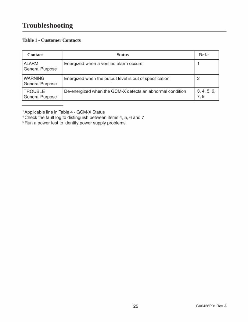
Table 1 - Customer Contacts
1 Applicable line in Table 4 - GCM-X Status4 Check the fault log to distinguish between items 4, 5, 6 and 75 Run a power test to identify power supply problems
Troubleshooting
Contact Status Ref.1
ALARMGeneral Purpose
Energized when a verified alarm occurs
WARNINGGeneral Purpose
TROUBLEGeneral Purpose
Energized when the output level is out of specification
De-energized when the GCM-X detects an abnormal condition
1
2
3, 4, 5, 6,7, 9
26GA0456P01 Rev. A
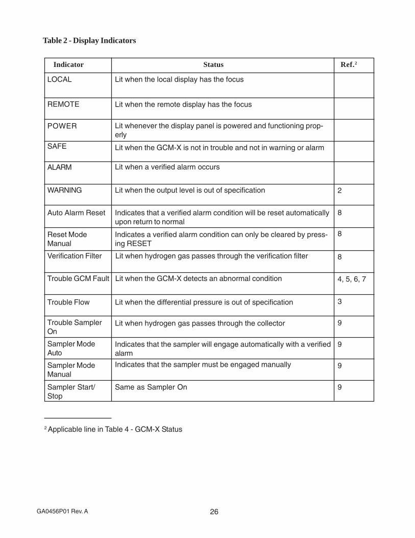
Table 2 - Display Indicators
Indicator Status Ref.2
LOCAL Lit when the local display has the focus
REMOTE
POWER
Lit when the remote display has the focus
Lit whenever the display panel is powered and functioning prop-erly
SAFE Lit when the GCM-X is not in trouble and not in warning or alarm
WARNING Lit when the output level is out of specification
Auto Alarm Reset Indicates that a verified alarm condition will be reset automaticallyupon return to normal
Reset ModeManual
Indicates a verified alarm condition can only be cleared by press-ing RESET
Verification Filter Lit when hydrogen gas passes through the verification filter
Trouble GCM Fault Lit when the GCM-X detects an abnormal condition
Trouble Flow Lit when the differential pressure is out of specification
2
8
8
8
4, 5, 6, 7
ALARM
9
Lit when a verified alarm occurs
Trouble SamplerOn
Sampler ModeAuto
Sampler ModeManual
Sampler Start/Stop
Lit when hydrogen gas passes through the collector
Indicates that the sampler will engage automatically with a verifiedalarm
Indicates that the sampler must be engaged manually
Same as Sampler On
9
9
9
3
2 Applicable line in Table 4 - GCM-X Status

27 GA0456P01 Rev. A
Table 3 - Display Keys
Key Function Ref.3
Reset Clear a verified alarm
Reset Mode
Verification Filter
Toggle “automatically reset alarm upon return to normal condi-tions” on and off
Manually activate the verification filter
Sampler Mode Toggle “automatically start collecting a sample for analysis” onand off
Sampler Start/Stop
Manually start collecting a sample for analysis
1
1
8
9
9
3 Applicable line in Table 4 - GCM-X Status
28GA0456P01 Rev. A
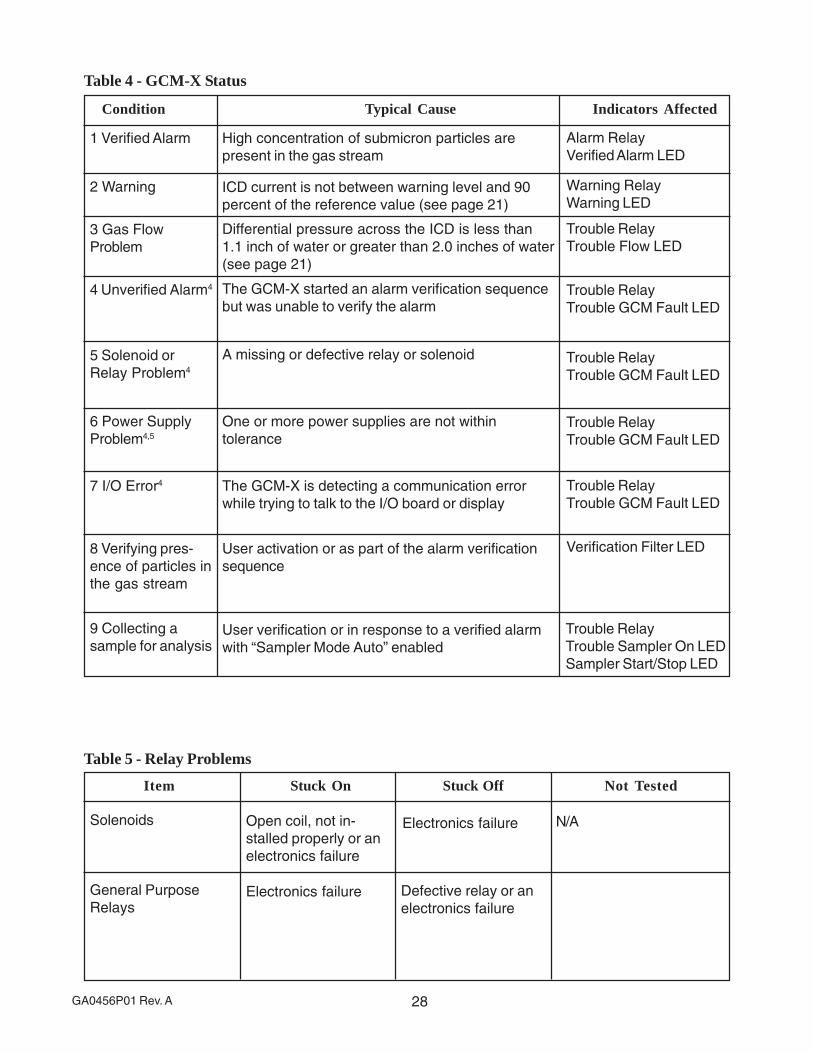
Table 4 - GCM-X Status
Condition Typical Cause Indicators Affected
1 Verified Alarm High concentration of submicron particles arepresent in the gas stream
2 Warning
3 Gas FlowProblem
ICD current is not between warning level and 90percent of the reference value (see page 21)
Differential pressure across the ICD is less than1.1 inch of water or greater than 2.0 inches of water(see page 21)
4 Unverified Alarm4 The GCM-X started an alarm verification sequencebut was unable to verify the alarm
6 Power SupplyProblem4,5
One or more power supplies are not withintolerance
7 I/O Error4 The GCM-X is detecting a communication errorwhile trying to talk to the I/O board or display
8 Verifying pres-ence of particles inthe gas stream
User activation or as part of the alarm verificationsequence
9 Collecting asample for analysis
User verification or in response to a verified alarmwith “Sampler Mode Auto” enabled
Alarm RelayVerified Alarm LED
Trouble RelayTrouble GCM Fault LED
Verification Filter LED
Trouble RelayTrouble Sampler On LEDSampler Start/Stop LED
5 Solenoid orRelay Problem4
A missing or defective relay or solenoid
Warning RelayWarning LED
Trouble RelayTrouble Flow LED
Trouble RelayTrouble GCM Fault LED
Trouble RelayTrouble GCM Fault LED
Trouble RelayTrouble GCM Fault LED
Table 5 - Relay Problems
Item Stuck On Stuck Off Not Tested
Solenoids Open coil, not in-stalled properly or anelectronics failure
Electronics failure N/A
General PurposeRelays
Electronics failure Defective relay or anelectronics failure
29 GA0456P01 Rev. A
Maintenance
Periodic Maintenance
The Generator Condition Monitor is designed for reliable, trouble-free operation and ease ofperiodic checks and maintenance.
Daily
Check GCM-X hydrogen flow and adjust if necessary. The output should be at 80 percent.POWER and SAFE indicators should be on.
Weekly
Push the VERIFICATION FILTER button at the GCM-X display panel. The indicator light shouldilluminate. There should be little or no change in flow or output. If the flow indication drops morethan 20 percent, the filter may be restricted. If the output increases significantly, particulate maybe present in the hydrogen.
Monthly
Perform RELAY TEST check (see SYSTEM description for instructions).
Annually
Check tubing connections annually, or whenever they have been disturbed. Use leak checksolution on joints, fittings and valve packing. Activate MANUAL sampler to obtain a backgroundsample at intervals recommended by the generator manufacturer.
When the Generator is Down
During periods where the generator is shut down, it is recommended that power be maintainedto the GCM-X, particularly during periods of high humidity, in order to maintain an elevated tem-perature within the ion chamber. This will serve to eliminate the possibility of condensationbuildup within the ion chamber. If power plant personnel wish to isolate the GCM-X while power isapplied and relieve hydrogen pressure from the instrument, close isolation valves A and B (seeFigure 2 - Piping Schematic) and place the auto sampler in manual mode by pressing thesampler mode button (see Figure A3).
If power plant personnel wish to isolate the GCM-X and relieve hydrogen pressure from theinstrument when power has been removed, close isolation valves A and B (see Figure 2 - PipingSchematic) and open isolation valves C and D. Please note that approximately 1 liter of hydro-gen will be released through isolation valves C and D.
Tubing and Fitting Replacement
The differential pressure measured by the flow gauge includes the drop in some of the internaltubing and fittings. If replacing tubing or fittings is necessary, replacements should be the samesize as the original in order to avoid changing the flow calibration. Environment One should benotified of instances where site personnel are performing such replacements. Plant manage-ment must assure that individuals performing such work are acting in accordance with Cenelecguidelines, local codes and generally accepted professional practice. Perform a leak checkwhenever any tubing connections are disturbed.
30GA0456P01 Rev. A
Component Replacement Instructions
The GCM-X was designed to facilitate component replacement, when and if it becomes neces-sary in the field. Several GCM-X components/assemblies may be removed by site personnel andforwarded to Environment One for evaluation repair/replacement, as noted below. In all otherinstances, the GCM-X will need to be returned to Environment One for servicing, or an Environ-ment One technician will be required on site.
Plant management is to assure that individuals performing work on the GCM-X are adequatelytrained to do so and that they work in accordance with Cenelec requirements, local codes andgenerally accepted professional practice.
If oil contamination is suspected, Environment One recommends that the GCM-X be returned forcomprehensive evaluation, cleaning and repair.
After the GCM-X has been installed and commissioned, individuals performing servicework on the electronics must wear an electrostatic wriststrap.
ICD, Filter Solenoid and Sampling System Solenoid
The Ion Chamber Detector (ICD) (GD0013G04), Filter Solenoid Assembly, Sampling SystemSolenoid Assembly and GCM-X Heater (GA0363P01) are mounted on the GCM-X “mountingplate,” which is an aluminum plate attached to the GCM-X frame by four 3/8-inch nuts. Removalof any of the mounted components is best accomplished by removing the back plate first andthen removing the individual assembly.
To remove the mounting plate:
· Disconnect power from the GCM-X.
· Detach the heater from the mounting plate by removing the four screws on the heater’smounting bracket.
· Detach grounding wire and other cables from the four wire ties.
· Detach solenoid coils from the two solenoid valves.
· Detach tubing connections from assemblies mounted to the mounting plate.
· Remove the four 3/8-inch bolts that secure the mounting plate to the GCM-X frame.
Each of the respective components mounted on the GCM-X back plate can then be removed forservice, replacement or return to Environment One. To re-install the assemblies, reverse theprocess above.
Processor Assembly
The Processor Assembly (GA0449G01) (GD0082G02+GA0396P03) is located in the flameproofenclosure, which is referred to as the System Electronics. To remove the Controller Assembly:
1. Disconnect power from the GCM-X.

31 GA0456P01 Rev. A
2. Open cover of the flameproof enclosure, taking care not to damage the surfaces.
3. Remove the molex connectors at J3 and J4.
4. Detach the ribbon cable at J2.
5. Detach the BNC connector at right-hand side of circuit board.
6. Remove the four nuts from the mounting studs.
7. Remove the assembly from the enclosure.
8. Install in reverse process.
I/O Assembly (Located in the System Electronics Enclosure)
The I/O Assembly (GD0094G08 Rev. -) is located in the flameproof enclosure, referred to as theSystem Electronics. To remove the I/O Assembly:
1. Disconnect power from the GCM-X.
2. Open the cover of the flameproof enclosure, taking care not to damage the surfaces.
3. Remove the Processor Assembly (see above).
4. Remove all wiring connections to TB1 and TB2 on the I/O board.
5. Remove the molex power supply connectors at J4 and J5.
6. Remove the RFI filter connection at J6.
7. Remove the four standoffs that connected the processor board to the I/O board.
8. Remove assembly from enclosure.
9. Install in reverse process.
Display Assembly
The Display Assembly (GD0052G01 Rev. -) is located behind the GCM-X subdoor, which isintegral to the GCM-X module assembly. To remove the Display Assembly:
1. Disconnect power from the GCM-X.
2. Open the GCM-X front door.
3. Open the GCM-X subdoor, which will enable access to the GCM-X Display Panel.
4. Disconnect the 15-pin D-connector from the back of the display board.
5. Loosen the four display assembly mounting screws located on the back side of the GCM-Xmodule (support the display assembly with your other hand).
6. Detach the grounding wire and remove the display assembly.
(Processor Assembly cont’d)

32GA0456P01 Rev. A
Fuses
The GCM-X contains a 2A slo-blo fuse that may be replaced by plant personnel. The fuse islocated on the I/O board, adjacent to the power and heater connections. It is labeled “F1.”
· Disconnect power from the GCM-X.
· Open the cover of the flameproof enclosure, taking care not to damage the surfaces.
· Use a fuse puller to remove the fuse.
· Replace fuse with Littlefuse #218 002 or equivalent.
· Replace flameproof enclosure cover and secure.
33 GA0456P01 Rev. A
GCM-X Remote Panel
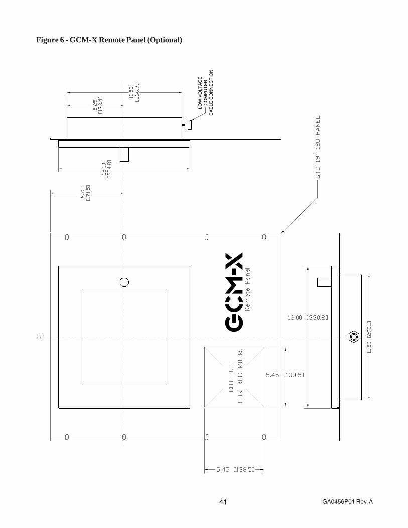
The GCM-X Remote Panel (GD0054GXX) is an optional standard 19-inch rack mount assemblythat provides remote display or remote control of the GCM-X. It is intended for use in a non-hazardous area only (typically the control room) and incorporates a lockable front door.
GCM-X in Local Mode
When the GCM-X is in local mode, the green local LED in the upper left-hand corner of the GCM-X display is illuminated. This indicates that control of the GCM-X is limited to the control/displaypanel mounted in the front door of the GCM-X (confirming the GCM-X unit has control). When theGCM-X is in the local mode, the GCM-X Remote Panel will simultaneously display all indicatorsand output as they appear at the GCM-X unit, including the local indication.
GCM-X in Remote Mode (Optional)
Control of the GCM-X can be transferred to the GCM-X Remote Panel by pressing the Fn (Func-tion) key on the GCM-X display and then pressing ENTER when the display scrolls to the promptGO REMOTE. When GO REMOTE has been selected, the green remote LED in the upper-lefthand corner of the GCM-X display will illuminate, indicating that control has been passed fromthe GCM-X to the GCM-X Remote Panel.
Transferring Control from the GCM-X Remote Panel (Optional)
Transferring control of the GCM-X back to the local mode is accomplished by pressing the Fn(Function) key on the GCM-X Remote Panel display and then pressing ENTER when the displayscrolls to the prompt GO LOCAL. When GO LOCAL has been selected, the green local LED inthe upper-left hand corner of the GCM-X Remote Panel display (and the GCM-X display) willilluminate, indicating that control has been passed from the GCM-X Remote Panel back to theGCM-X.
See Figures 4 and 6 for details regarding GCM-X Remote Panel installation. Interconnectingcable between the GCM-X and the GCM-X Remote Panel should be Environment OneHA0073P01, or Black Box SME EDN 12A 24AWG Stranded, or equal.
Removing the GCM-X Remote Panel’s Display Assembly (Optional)
· Disconnect power from the GCM-X Remote Panel.
· Confirm that an electrostatic discharge wristband is being worn.
· Open the GCM-X Remote Display door, which will enable access to the GCM-X RemotePanel’s display assembly.
· Loosen the four mounting screws located on the back side of the GCM-X Remote Panel(ensure that the display assembly is supported with your hand or by someone else).
· Upon completely loosening the four mounting screws, detach the ground wire and removethe GCM-X Remote Panel display assembly.
Reverse the process to reinstall.

34GA0456P01 Rev. A
GCM-X - Parts List
Description Part Number
GCM-X Instruction Manual GA0456P01
GCM-X Remote Panel Assembly GD0054G01 (optional)
Processor Assembly (Circuit Board) GD0082G02
I/O Assembly (Circuit Board) GD0094G08
Display Assembly (with Circuit Board) GD0052G01
Ion Chamber Detector GD0013G06
Filter Cartridge GA0150P01
2-Way Solenoid Valve GA0422P02 (12 VDC)
3-Way Solenoid Valve GA0422P01 (12 VDC)
Transmitter HA0058P07
Collector GA0349G01
Power supply (+12V) HA0027P01
Alpha Source Assembly GA0281G02
Isolation Barrier (DC) DA0105P05
Isolation Barrier (AC) DA0105P04
Ion Chamber Heater GA0363P01
35 GA0456P01 Rev. A
Figure 1 - System Overview

36GA0456P01 Rev. A
Figure 2 - Piping Schematic
NO
TE
S:
1.
TO
AV
OID
PO
TE
NT
IAL
OIL
CO
NT
AM
INA
TIO
N, T
AP
S I
N G
EN
ER
AT
OR
SH
OU
LD
NO
T B
E L
OC
AT
ED
IN
BO
TT
OM
OF
CA
SE
2. A
LL
PIP
ING
SH
AL
L B
E"
[21
.3] O
D3
. S
TA
ND
AR
D P
IPIN
G P
RA
CT
ICE
SH
OU
LD
BE
FO
LL
OW
ED
TO
AV
OID
LIQ
UID
CO
NT
AM
INA
TIO
N O
F T
HE
GC
M-X
4. T
YP
ICA
L D
RIP
LE
G V
OL
UM
E I
S 1
LIT
ER
MIN
IMU
M5
. A
MIN
IMU
M F
AN
DIF
FE
RE
NT
IAL
OF
4"-
5"
[10
2-1
27
] O
F W
AT
ER
IS
RE
QU
IRE
D F
OR
OP
ER
AT
ION
6.
FO
R G
E I
NS
TA
LL
AT
ION
RE
FE
R T
O O
PT
ION
AL
AU
TO
SA
MP
LE
R C
ON
NE
CT
ION
7. A
VO
ID P
IPIN
G A
RR
AN
GE
ME
NT
S T
HA
T C
AN
DIS
RU
PT
ST
AB
LE
, C
ON
SIS
TE
NT
FL
OW
TO
TH
E G
CM
-X
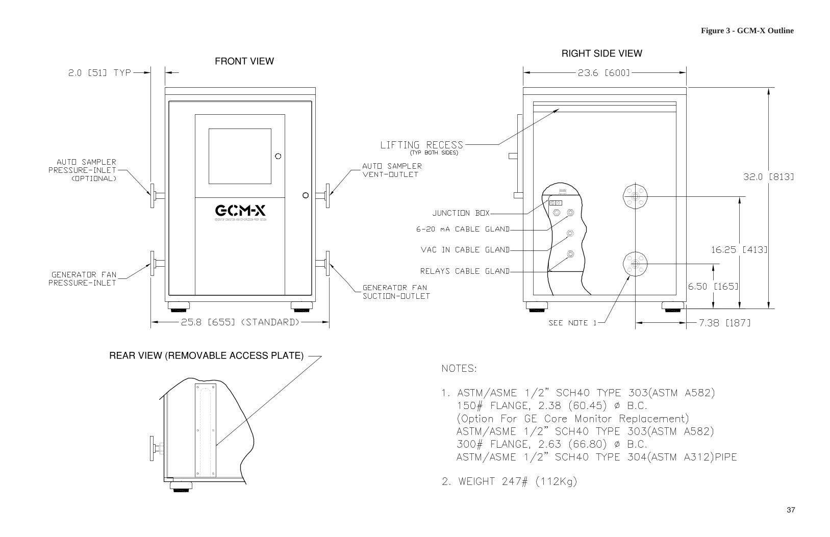
Figure 3 - GCM-X Outline
37
gcm-x
FRONT VIEW
REAR VIEW (REMOVABLE ACCESS PLATE)
RIGHT SIDE VIEW

38GA0456P01 Rev. A
39 GA0456P01 Rev. A
Figure 4 - Customer Interface Wiring
40GA0456P01 Rev. A
Figure 5 - ICD Current and Flow
HY
DR
OG
EN
GA
UG
E P
RE
SS
UR
E, B
AR
VO
LU
ME
TR
IC F
LO
W A
S F
UN
CT
ION
S O
F H
YD
RO
GE
N P
RE
SS
UR
E
3
CURRENT, PICOAMPS
1 L
ITE
R/M
INU
TE
(LP
M)=
.0353 C
FM
1 B
AR
= 1
00
KP
A =
14
.5 P
SIG
ST
AN
DA
RD
LP
M~
VO
LU
ME
TR
IC L
PM
X(B
AR
+1)
01
12
23
45
456
15
VOLUMETRIC FLOW, LPM
76
8
FLO
W
9
0
10
10 5
CU
RR
EN
T
GC
M-X
FLO
W =
1.5
TY
PIC
AL IO
N C
HA
MB
ER
OU
TP
UT
CU
RR
EN
T A
ND
20
25
30
41 GA0456P01 Rev. A
Figure 6 - GCM-X Remote Panel (Optional)
GC
M-X
LO
W V
OLT
AG
E
CO
MP
UT
ER
CA
BLE
CO
NN
EC
TIO
N

42GA0456P01 Rev. A
Figure A1 - Front View, GCM-X

43 GA0456P01 Rev. A
Figure A2 - Back View, GCM-X

44GA0456P01 Rev. A
Figure A3 - GCM-X Display, Front View
45 GA0456P01 Rev. A
Figure A4 - GCM-X Display - Backside of Door, “Cold Start” Button Access
PRESS RESET BUTTON
IMMEDIATELY
AFTER APPLYING POWER
46GA0456P01 Rev. A
Appendix A
Generator Condition Monitor Output Traces
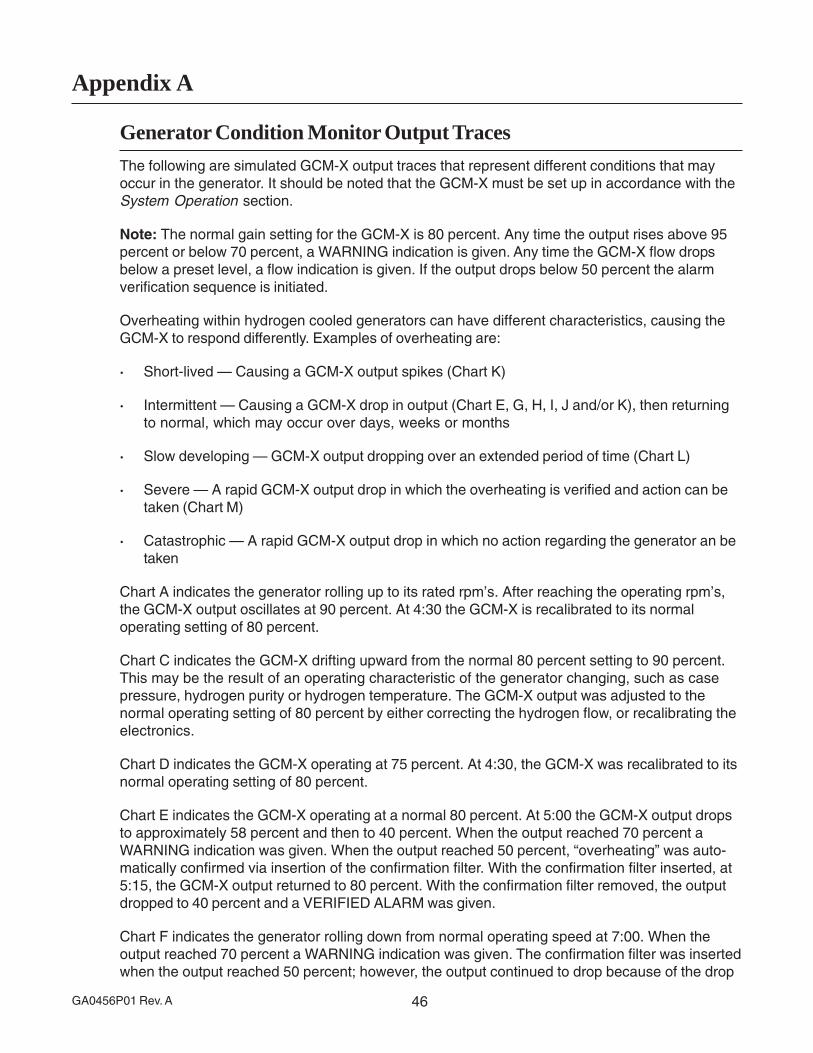
The following are simulated GCM-X output traces that represent different conditions that mayoccur in the generator. It should be noted that the GCM-X must be set up in accordance with theSystem Operation section.
Note: The normal gain setting for the GCM-X is 80 percent. Any time the output rises above 95percent or below 70 percent, a WARNING indication is given. Any time the GCM-X flow dropsbelow a preset level, a flow indication is given. If the output drops below 50 percent the alarmverification sequence is initiated.
Overheating within hydrogen cooled generators can have different characteristics, causing theGCM-X to respond differently. Examples of overheating are:
· Short-lived — Causing a GCM-X output spikes (Chart K)
· Intermittent — Causing a GCM-X drop in output (Chart E, G, H, I, J and/or K), then returningto normal, which may occur over days, weeks or months
· Slow developing — GCM-X output dropping over an extended period of time (Chart L)
· Severe — A rapid GCM-X output drop in which the overheating is verified and action can betaken (Chart M)
· Catastrophic — A rapid GCM-X output drop in which no action regarding the generator an betaken
Chart A indicates the generator rolling up to its rated rpm’s. After reaching the operating rpm’s,the GCM-X output oscillates at 90 percent. At 4:30 the GCM-X is recalibrated to its normaloperating setting of 80 percent.
Chart C indicates the GCM-X drifting upward from the normal 80 percent setting to 90 percent.This may be the result of an operating characteristic of the generator changing, such as casepressure, hydrogen purity or hydrogen temperature. The GCM-X output was adjusted to thenormal operating setting of 80 percent by either correcting the hydrogen flow, or recalibrating theelectronics.
Chart D indicates the GCM-X operating at 75 percent. At 4:30, the GCM-X was recalibrated to itsnormal operating setting of 80 percent.
Chart E indicates the GCM-X operating at a normal 80 percent. At 5:00 the GCM-X output dropsto approximately 58 percent and then to 40 percent. When the output reached 70 percent aWARNING indication was given. When the output reached 50 percent, “overheating” was auto-matically confirmed via insertion of the confirmation filter. With the confirmation filter inserted, at5:15, the GCM-X output returned to 80 percent. With the confirmation filter removed, the outputdropped to 40 percent and a VERIFIED ALARM was given.
Chart F indicates the generator rolling down from normal operating speed at 7:00. When theoutput reached 70 percent a WARNING indication was given. The confirmation filter was insertedwhen the output reached 50 percent; however, the output continued to drop because of the drop
47 GA0456P01 Rev. A
in hydrogen flow. In this case, WARNING, LOW FLOW and GCM FAULT indications were given.
Chart G indicates the GCM-X operating at a normal 80 percent. At 5:00 the output drops to 52percent. When the output reached 70 percent a WARNING indication was given. Since theoutput did not reach the 50 percent (alarm level), the alarm was not confirmed. The alarm couldhave been confirmed manually if he confirmation filter was manually inserted.
Chart H indicates the GCM-X operating at a normal 80 percent. At 5:00 the output began to drop.When the output reached 70 percent a WARNING indication was given. When the outputreached 50 percent, “overheating” was automatically confirmed via actuation of the confirmationfilter. With the confirmation filter inserted, at 5:10, the GCM-X output returned to 80 percent. Withthe confirmation filter removed, the output dropped to 50 percent and a VERIFIED ALARM wasgiven.
Chart I indicates the GCM-X operating at a normal 80 percent. At 5:40 the output began to drop.When the output reached 70 percent a WARNING indication was given. Since the output did notreach the 50 percent (alarm level), the alarm was not confirmed. A WARNING was indicated.The alarm could have been confirmed manually if the confirmation filter was manually inserted.
Chart J indicates the GCM-X operating at a normal 80 percent. At 6:30 the output began to drop.When the output reached 70 percent a WARNING indication was given. When the outputreached 50 percent, “overheating” was automatically confirmed via insertion of the confirmationfilter. With the confirmation filter inserted, at 6:35 the GCM-X output returned 80 percent. With theconfirmation filter removed, the output dropped to 20 percent and a VERIFIED ALARM wasgiven.
(Generator Condition Monitor Output Traces cont’d)

48GA0456P01 Rev. A
10
0%
90
80
70
60
50
40
30
20
10
0%
10:00
9:00
8:00
7:00
6:00
5:00
4:00
3:00
2:00
1:00
10
0%
90
80
70
60
50
40
30
20
10
0%
10:00
9:00
8:00
7:00
6:00
5:00
4:00
3:00
2:00
1:00
10
0%
90
80
70
60
50
40
30
20
10
0%
10:00
9:00
8:00
7:00
6:00
5:00
4:00
3:00
2:00
1:00
10
0%
90
80
70
60
50
40
30
20
10
0%
10:00
9:00
8:00
7:00
6:00
5:00
4:00
3:00
2:00
1:00
MNXIWVNMWIMNXIWVNMWI
MNXIWVNMWIMNXIWVNMWI
MNXIWVNMWIMNXIWVNMWI
MNXIWVNMWIMNXIWVNMWI
MNXIWVNMWIMNXIWVNMWI
MNXIWVNMWIMNXIWVNMWI
MNXIWVNMWIMNXIWVNMWI
MNXIWVNMWIMNXIWVNMWI
MNXIWVNMWIMNXIWVNMWI
MNXIWVNMWIMNXIWVNMWI
MNXIWVNMWIMNXIWVNMWI
MNXIWVNMWIMNXIWVNMWI
MNXIWVNMWI
MNXIWVNMWIMNXIWVNMWI
MNXIWVNMWIMNXIWVNMWI
MNXIWVNMWIMNXIWVNMWI
MNXIWVNMWIMNXIWVNMWI
MNXIWVNMWI
MNXIWVNMWI
MNXIWVNMWIMNXIWVNMWI
MNXIWVNMWIMNXIWVNMWI
MNXIWVNMWIMNXIWVNMWI
MNXIWVNMWIWIVNMNXIWVNMWIWIVN
MNXIWVNMWIMNXIWVNMWI
MNXIWVNMWIMNXIWVNMWI
MNXIWVNMWIMNXIWVNMWI
MNXIWVNMWIMNXIWVNMWI
MNXIWVNMWIMNXIWVNMWIMNXIWVNMWIMNXIWVNMWIMNXIWVNMWIMNXIWVNMWIMNXIWVNMWIMNXIWVNMWIMNXIWVNMWI
MNXIWVNMWIMNXIWVNMWIMNXIWVNMWIMNXIWVNMWIMNXIWVNMWIMNXIWVNMWIMNXIWVNMWIMNXIWVNMWIMNXIWVNMWIMNXIWVNMWIMNXIWVNMWI
Ch
art M
ove
me
nt
Ch
art M
ove
me
nt
Ch
art M
ove
me
nt
Ch
art M
ove
me
nt
AC
BD
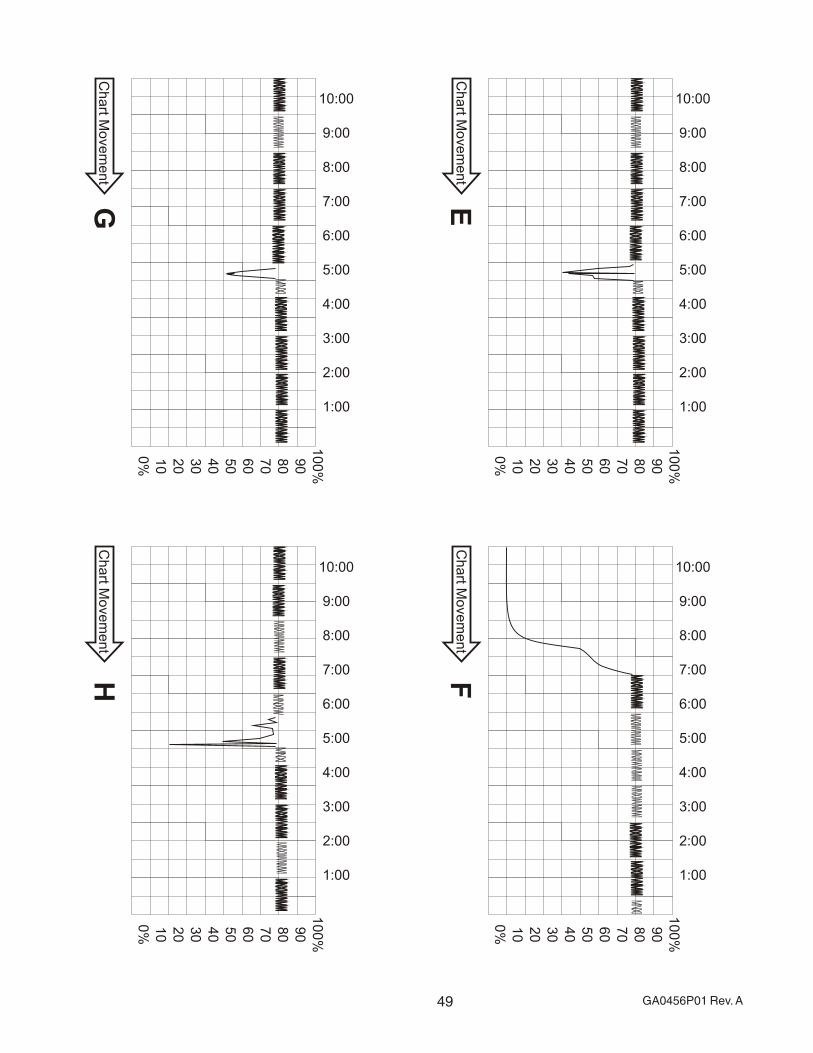
49 GA0456P01 Rev. A
10
0%
90
80
70
60
50
40
30
20
10
0%
10:00
9:00
8:00
7:00
6:00
5:00
4:00
3:00
2:00
1:00
10
0%
90
80
70
60
50
40
30
20
10
0%
10:00
9:00
8:00
7:00
6:00
5:00
4:00
3:00
2:00
1:00
10
0%
90
80
70
60
50
40
30
20
10
0%
10:00
9:00
8:00
7:00
6:00
5:00
4:00
3:00
2:00
1:00
10
0%
90
80
70
60
50
40
30
20
10
0%
10:00
9:00
8:00
7:00
6:00
5:00
4:00
3:00
2:00
1:00
MNXIWVNMWIMNXIWVNMWI
MNXIWVNMWIMNXIWVNMWI
MNXIWVNMWIMNXIWVNMWI
MNXIWVNMWIMNXIWVNMWIMNXIWVNMWI
MNXIWVNMWIMNXIWVNMWI
MNXIWVNMWIMNXIWVNMWI
MNXIWVNMWIMNXIWVNMWI
MNXIWVNMWIMNXIWVNMWI
MNXIWVNMWI
MNXIWVNMWIMNXIWVNMWIMNXIWVNMWI
MNXIWVNMWIMNXIWVNMWI
MNXIWVNMWI
MNXIWVNMWIMNXIWVNMWI
MNXIWVNMWIMNXIWVNMWI
MNXIWVNMWIMNXIWVNMWI
MNXIWVNMWIMNXIWVNMWI
MNXIWVNMWIMNXIWVNMWIMNXIWVNMWI
MNXIWVNMWIMNXIWVNMWI
MNXIWVNMWIMNXIWVNMWI
MNXIWVNMWIMNXIWVNMWI
MNXIWVNMWIMNXIWVNMWI
MNXIWVNMWIMNXIWVNMWI
MNXIWVNMWIMNXIWVNMWI
MNXIWVNMWIMNXIWVNMWI
MNXIWVNMWIMNXIWVNMWI
MNXIWVNMWIMNXIWVNMWI
MNXIWVNM
WIM
NXIWVNMWI
MNXIW
MNXIWVNMWIMNXIWVNMWI
MNXI
MNXI
MNXI
MNXI
Ch
art M
ove
me
nt
Ch
art M
ove
me
nt
Ch
art M
ove
me
nt
Ch
art M
ove
me
nt
EG
FH
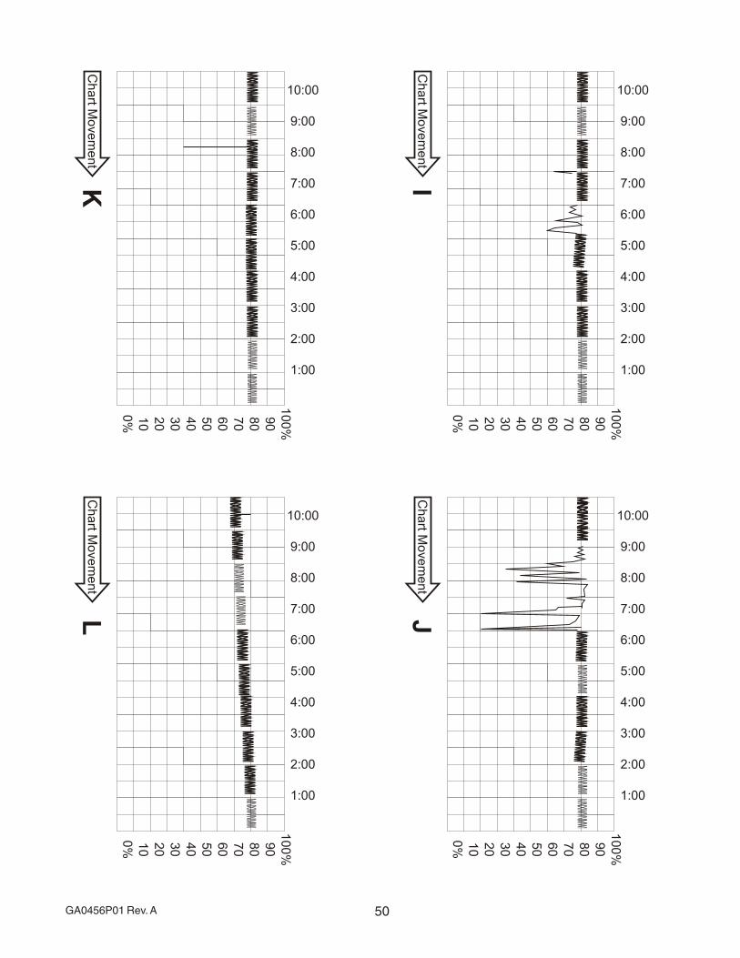
50GA0456P01 Rev. A
10
0%
90
80
70
60
50
40
30
20
10
0%
10:00
9:00
8:00
7:00
6:00
5:00
4:00
3:00
2:00
1:00
10
0%
90
80
70
60
50
40
30
20
10
0%
10:00
9:00
8:00
7:00
6:00
5:00
4:00
3:00
2:00
1:00
10
0%
90
80
70
60
50
40
30
20
10
0%
10:00
9:00
8:00
7:00
6:00
5:00
4:00
3:00
2:00
1:00
10
0%
90
80
70
60
50
40
30
20
10
0%
10:00
9:00
8:00
7:00
6:00
5:00
4:00
3:00
2:00
1:00 MNXIWVNMWIMNXIWVNMWI
MNXIWVNMWIMNXIWVNMWI
MNXIWVNMWIMNXIWVNMWI
MNXIWVNMWIMNXIWVNMWI
MNXIWVNMWI
MNXIWVNMWIMNXIWVNMWI
MNXIWVNMWIMNXIWVNMWIMNXIWVNMWI
MNXIWVNMWIMNXIWVNMWI
MNXIWVNMWIMNXIWVNMWI
MNXIWVNMWI
MNXIWVNMWIMNXIWVNMWI
MNXIWVNMWIMNXIWVNMWI
MNXIWVNMWIMNXIWVNMWI
MNXIWVNMWIMNXIWVNMWI
MNXIWVNMWI
MNXIWVNMWI
MNXIWVNMWIMNXIWVNMWI
MNXIWVNMWIMNXIWVNMWI
MNXIWVNMWIMNXIWVNMWI
MNXIWVNMWIMNXIWVNMWI
MNXIWVNMWIMNXIWVNMWI
MNXIWVNMWIMNXIWVNMWI
MNXIWVNMWIMNXIWVNMWI
MNXIWVNMWIMNXIWVNMWI
MNXIWVNMWIMNXIWVNMWI
MN
XIWVN
MW
IM
NXIW
VNM
WI
MNXIWVNMWIMNXIWVNMWI
MNXIWVNMWIMNXIWVNMWI
MNXIWVNMWIMNXIWVNMWI
MNXIWVNMWIMNXIWVNMWI
MNXIWVNMWIMNXIWVNMWIMNXIWVNMWI
Ch
art M
ove
me
nt
Ch
art M
ove
me
nt
Ch
art M
ove
me
nt
Ch
art M
ove
me
nt
IK
JL
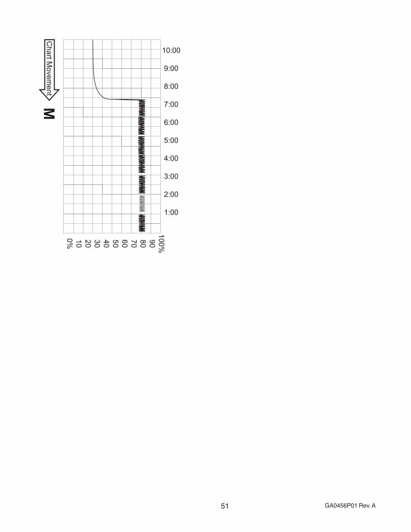
51 GA0456P01 Rev. A
10
0%
90
80
70
60
50
40
30
20
10
0%
10:00
9:00
8:00
7:00
6:00
5:00
4:00
3:00
2:00
1:00MNXIWVNMWIMNXIWVNMWI
MNXIWVNMWIMNXIWVNMWI
MNXIWVNMWIMNXIWVNMWIMNXIWVNMWI
MNXIWVNMWIMNXIWVNMWI
MNXIWVNMWIMNXIWVNMWI
MNXIWVNMWIMNXIWVNMWI
Ch
art M
ove
me
nt
M

52GA0456P01 Rev. A

Environment One Corporation2773 Balltown RoadNiskayuna, New York USA 12309–1090
Tel: (01) 518.346.6161Fax: 518.346.6188
www.eone.com
A PCC Flow Technologies, Inc. Company
![FCM Workflow using GCM. Agenda Polling Mechanism What is GCM Need / advantages of GCM GCM Architecture Working of GCM GCM – Send to Sync [ HTTP ] and](https://img.pdfslide.us/doc/110x75/5697bfba1a28abf838ca07e2/fcm-workflow-using-gcm-agenda-polling-mechanism-what-is-gcm-need-advantages.jpg)