Embed Size (px)
Citation preview
LA-12773
-—.
COPY F1S4 REPORT SECTION .x_
LB -12773
c. 3
Generation of Ultra-High
Magnetic Fields for AGEX
Los AlamosNATIONAL LABORATORY
Los Alamos National bzboratoy is operated by the University of Cal~omia
fir the united States Department of EnergyundercontractW-7405-ENG36.
Edited by Patricia W.Mendius, ClC-l
Prepared by Clara DeMaria, X-DO
An Aflrmatiw Action fEqz/al Opportunity Employer
This report was prepared as an account of work sponsored by an agency of theUnited States Gowrnment. Neither The Regents of the University of Calijomia, theUnited States Government nor any agency thereoj nor any of their employees, makes anywarranty, express or implied, or assumes any tegal liabilityor rqzvrsibilityfir the accuracy,completeness,or usefulness of any information, apparatus, product, or processdkdosed, orrepresents that its use would not infinge pn”vatelyoumed rights. Rgference herein to any qnmficcommercial product, process, or service by trade name, trademark, manufacturer, or otherwise, doesnot necessarily constitute or imply its endorsement, recommendation, or fawn”ng by The Regentsof the University of Calt~onsia,the United StatesGouemmenf, or any agency thereof. The virwsand opinions of authors expressed herein do not necessarily state or reflect thoseqfThe Regents ofthe Uniwrsity of_Cal~omia, the United States Government, or any agency therecf.
LA-12773
1
UC-741 and UC-7(XIhSUt?d: August 1994
Generation of Ultra-High
Magnetic Fieldsfor AGEX
Maurice G. Sheppard
C. Max Fowler
Bruce L.. Freeman
..
.
—..
Los AlamosNATIONAL LABORATORY
. .
Los Alamos, New Mexico 87545
GENERATION OF ULTRA-HIGH MAGNETIC FIELDS FOR AGEX
by
Maurice G. Sheppard, C. Max Fowler, and Bruce L. Freeman
ABSTRACT
Generation of ultra-high magnetic fields of 10-25 MG (0.4-2.5 MJ/cmq)using high-explosive-driven magnetic flux-compression is one approachwhich could enhance the U.S. Above Ground Experimental (AGEX)capability. The beginnings of a U.S.-Russian collaboration to generate20 MG by extending flux-compression technology are described. Thefirst joint experiments, planned for November 1993 at Los Alamos, willtest the Russian MC- 110 MG generator and will be followed by severalhigh-temperature superconductor experiments. Equation-of-state experi-ments involving isentropic compression at pressures of several megabarsare being considered as follow-on joint experiments. Magnetohydrody-namic (MHD) calculations of the MC-1 experiments using the 1D MHDcode RAVEN are presented, including comparisons and benchmarksagainst previous Russian experiments and calculations. The first jointexperiments will use Russian hardware and U.S. high-explosive. Gain-ing practical experience with the MC- 1 and benchmarking the RAVENpredictions for the performance of the modified generator are importantfirst steps towards reaching the 20 MG goal.
Introduction
Energy densities associated with magneticfields of 10-25 MG (0.4-2.5 J/cmq) represent apotential energy source for Above GroundExperiments (AGEX). Possible relevant usesfor ultra-high magnetic fields include magneti-cally driven liner implosions for x-ray produc-tion, adiabatic (isentropic) compression ofmaterials at pressures exceeding 10 Mb forequation-of-state studies, neutron productionthrough fusion plasma confinement or compres-sion, and high-power microwave production.
Scientists from Los Alamos National Labora-
tory andtheRussiannuclearweaponslaboratory
at Arzamas- 16 are collaborating on ultra-highmagnetic field experiments using explosivepulsed power. This collaboration, made possiblefor the first time by the end of the Cold War, willallow the scientific exchange of unclassifiedknowledge, data, and experience which has beeninaccessible to the general scientific communitybecause of its proximity to each country’snuclear weapons program. The first series ofexperiments will use the Russian MC- 1 flux-compression generator (FCG), designed andperfected by the late A. I. Pavlovskii and hiscolleagues.1 The MC-1 was assembled withU.S. high-explosives (HE) and diagnostics tomeasure the upper critical field transition,
1
HCZ(T),of the high-temperature superconductor(HTSC), YBa2Cu3@ (YBCO), at temperaturesof 4 K and higher. Experiments should com-mence in November 1993 at Los Alamos.
The scope of this paper is limited to a presen-tation of ID MHD simulations of the MC-1 withthe Lagrangian RAVEN code; this paper is notintended to be a complete report of theU.S.-Russian collaboration. A general discus-sion of ultra-high magnetic field generation inthe next section is followed by a description ofthe MC- 1 FCG and a review of the Russianexperience with this generator. The fourthsection gives details of RAVEN calculationswith different types of HE and varying initialfields. These calculations are compared withRussian calculations and experimental results.Preshot calculations for the HTSC experimentsand possible isentropic compression experimentsfor equation-of-state studies are also included.
Generation of Ultra-High Magnetic Fields
Generating 10 MG magnetic fields, orgreater, in volumes large enough for diagnosticsand macroscopic experiments presents specialchallenges associated with high energies, highenergy densities, very large magnetic pressures,and magnetic induced plasma instabilities. Theprimary mechanism for creating such fields isexplosively-driven magnetic flux-compression.A seed field is first generated and trapped in avolume which is surrounded by electrical con-ductors. Then, a conducting armature, driven byHE, wipes out the volume while doing workagainst the trapped field -- thus amplifying it.An excellent review of flux-compression funda-mentals appears in Fowler, Caird, and Gam.2
To illustrate the magnitude of the challengepresented by ultra-high fields, consider thefollowing discussion. The energy density associ-ated with 10 MG is 0.4 MJ/ems, whereas thechemical energy released upon HE detonation isonly 9 x 10⁻³MJ/cmq. Furthermore, the mag-netic pressure associated with 10 MG is 4 Mb-- an order of magnitude above typical HEpressures. Since energies and pressures scale asthe square of the magnetic field, the difficulty of
2
the task and the richness of the payoff skyrocketwith higher fields. The trick is to efficientlyconvert large amounts of HE chemical energyinto kinetic energy of an armature. The armaturemust then wipe out the high inductance volumein a short enough time that the trapped magneticfield neither diffuses out of nor destroys itsconfining walls. At the 10 MG level, andslightly higher, the Russian scientists atArzamas-16 have demonstrated repeatable andreliable performance with the MC- 1.3>4
MC-1 Description
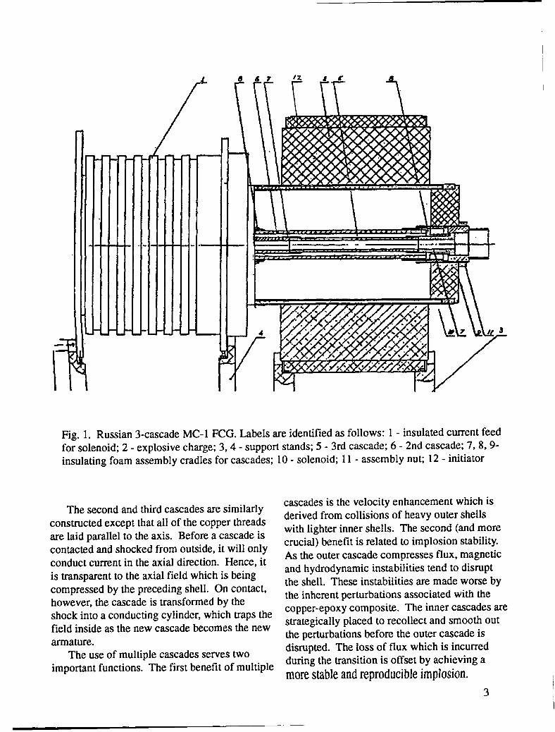
A diagram of the Russian three-cascadeMC-1 FCG is presented in Fig. 1. The HEcylinder, which in the Russian experiments hasbeen composed of a 50/50 RDIUTNT mix, isdetonated simultaneously on its outer diametersurface by a ring of 10 polystyrene block initia-tors.
Inside the HE are 3 concentric cylindricalshells (known as cascades in the Russian litera-ture), made of a unique copper-epoxy composite.These shells successively take on the role ofarmature during implosion. The shells are madeof hundreds of 0.25-mm diameter, enamel-coated, copper threads arranged side-by-side inlayers and secured in a casting of epoxy. The500 copper threads of the outer cascade arewound in a 2-turn solenoid and then broughtback along the outside diameter, parallel with thecylindrical axis, to complete the return currentpath. The solenoid cascade is impregnated withepoxy and cured. The outside diameters of all 3cascades, which are cast with a thicker layer ofepoxy, are machined smooth to inhibit hydrody-namic instabilities. An initial magnetic field ofup to 220 kG (typically 130-160 kG) is createdby discharging a capacitor through the firstcascade. The discharge is timed so that peakfield is achieved just as the HE detonation wavereaches the first cascade. Upon contact the HEshock breaks down the insulation between thesolenoid threads and transforms the first cascadeinto a conducting cylinder — trapping and thencompressing the initial field as the shell beginsto move.
II
—
—
—
I
867
r K
—
—
Fig. 1. Russian 3-cascade MC-1 FCG. Labels are identified as follows: 1- insulated current feedfo~solenoid; 2- explosive charge; 3,4- support stands; 5- 3rd cascade; 6- 2nd cascade; 7,8,9-insulating foam assembly cradles for cascades; 10- solenoid; 11- assembly nut; 12- initiator
The second and third cascades are similarlyconstructed except that all of the copper threadsare laid parallel to the axis. Before a cascade iscontacted and shocked from outside, it will onlyconduct current in the axial direction. Hence, itis transparent to the axial field which is beingcompressed by the preceding shell. On contact,however, the cascade is transformed by theshock into a conducting cylinder, which traps thefield inside as the new cascade becomes the newarmature.
The use of multiple cascades serves twoimportant functions. The first benefit of multiple
cascades is the velocity enhancement which isderived from collisions of heavy outer shellswith lighter inner shells. The second (and morecrucial) benefit is related to implosion stability.As the outer cascade compresses flux, magneticand hydrodynamic instabilities tend to disruptthe shell. These instabilities are made worse bythe inherent perturbations associated with thecopper-epoxy composite. The inner cascades arestrategically placed to recollect and smooth outthe perturbations before the outer cascade isdisrupted. The 10SSof flux which is incurredduring the transition is offset by achieving amorestableandreproducibleimplosion.
3
In the early systems developed by Fowler,Garn, and Caird,5 initial field coils were alsoplaced under the explosive charge. While verylarge fields were obtained (up to 14 MG), perfor-mance was erratic. The use of additionalPavlovskii cascades would presumably have ledto better reproducibility. An alternative approachto controlling the instabilities was investigatedby Caird et al.Gs7They placed the solenoidoutside of the HE and used a single stainlesssteel armature. On the timescales of the initialcapacitor discharge, the stainless steel armatureallowed magnetic flux to diffuse inside thecylinder; but on the short timescale of the implo-sion, the flux was essentially trapped and com-pressed. However, the poorer coupling of theinitial coils with the armature results in substan-tially lower initial, and, therefore, also finalcompressed fields.
Details for the First Experimental Series
The first of 5 tests of the MC-1 will be aproof test of the 3-cascade generator usingCOMP-B HE instead of the Russian 50/50 mix.COMP-B is slightly more energetic by virtue ofits 60/40 RDX/TNT composition. The generatorwill be preloaded to 160 kG using the capacitorbank at Point 88 in Ancho Canyon. Assumingsuccessful validation of the MC-1 performancein the first shot, the next 3 tests are designed tomeasure the critical field transition of YBCO.Finally, if everything goes as planned, the lastexperiment of this series will be another test ofthe 3-cascade system using PBX-9501 -- adramatically higher energy HE. Results of thesetests will be compared with the preshot calcula-tions described in the next section. Bench-marking of the RAVEN code at these high fieldsis a first step towards pursuing the 20 MG goal.
In the HTSC experiments, the third cascadewill be removed, and the volume inside thesecond cascade will be occupied by a 0.15 g/cm3foam cryostat. The YBCO sample, whichoccludes a 4-mm dielectric microwavewaveguide, and Faraday rotation diagnostics willbe bathed in liquid helium via channels in thefoam. As the field strength increases during the
4
compression, the YBCO film will undergo theHC2transition and become resistive. Before thetransition occurs, 94 GHz diagnostic micro-waves, which will be focused into one end of thewaveguide, will be largely reflected by thesuperconducting film. After the transition, themicrowaves will be increasingly transmitted anddetected.
ID MHD RAVEN Calculations
Simulations of the MC-1 have been con-ducted with the ID Lagrangian MHD codeRAVEN utilizing SESAME equations of state(EOS) and electrical conductivities.gtg Cascadeswere modeled as sandwiched layers of copperand epoxy. The number of layers used for eachcascade matches the actual number of layers ofcopper thread in each cascade, and the thicknessof the layers was adjusted to match the reportedaverage density of each cascade while fixing thetotal sandwich thickness. This approach differsfrom the Russian computational modcls,s whichuse a mixed copper-epoxy EOS and only onelayer per cascade shell. The Russians scaled astandard copper resistivity model by a factor of 5to use for the mixed EOS. The RAVEN calcula-tions treated each copper shell with an unscaledresistivity and each epoxy layer as an insulator.To allow the axial magnetic field to pass freelythrough the cascades until they were shocked inthe calculations, the standard copper resistivityin each zone was multiplied by a step functionwhich remained zero until the zone density firstexceeded 1% above normal density; subse-quently the step function stayed equal to one forthe remainder of the simulation.
3-Cascade MC-1 Simulations
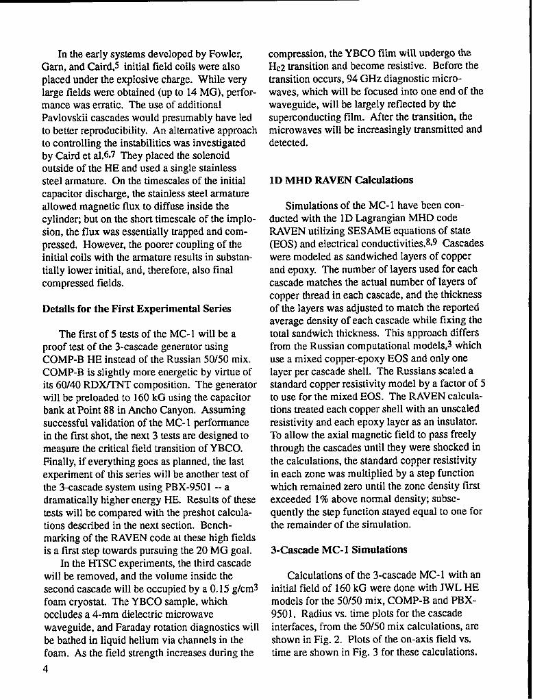
Calculations of the 3-cascade MC-1 with aninitial field of 160 kG were done with JWL HEmodels for the 50/50 mix, COMP-B and PBX-9501. Radius vs. time plots for the cascadeinterfaces, from the 50/50 mix calculations, arcshown in Fig. 2. Plots of the on-axis field vs.time are shown in Fig. 3 for these calculations.
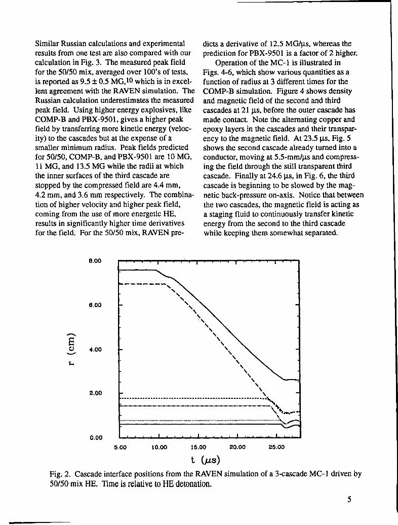
Similar Russian calculations and experimentalresults from one test are also compared with ourcalculation in Fig. 3. The measured peak fieldfor the 50/50 mix, averaged over 100’s of tests,is reported as 9.5A 0.5 MG, 10which is in excel-lent agreement with the RAVEN simulation. TheRussian calculation underestimates the measuredpeak field. Using higher energy explosives, likeCOMP-B and PBX-9501, gives a higher peakfield by transferring more kinetic energy (veloc-ity) to the cascades but at the expense of asmaller minimum radius. Peak fields predictedfor 50/50, COMP-B, and PBX-9501 are 10 MG,11 MG, and 13.5 MG while the radii at whichthe inner surfaces of the third cascade arestopped by the compressed field are 4.4 mm,4.2 mm, and 3.6 mm respectively. The combina-tion of higher velocity and higher peak field,coming from the use of more energetic HE,results in significantly higher time derivativesfor the field. For the 50/50 mix, RAVEN pre-
dicts a derivative of 12.5 MG/w, whereas theprediction for PBX-9501 is a factor of 2 higher.
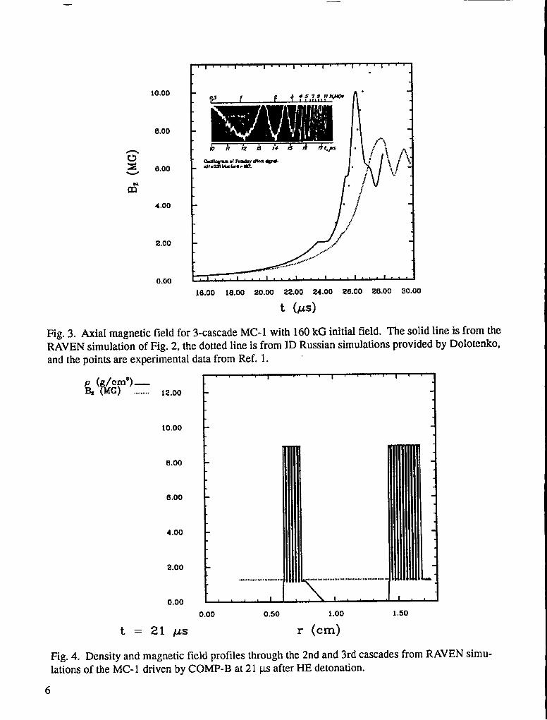
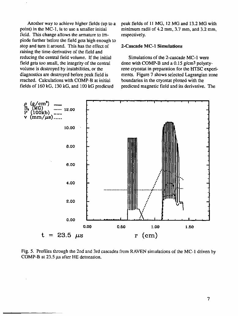
Operation of the MC-1 is illustrated inFigs. 4-6, which show various quantities as afunction of radius at 3 different times for theCOMP-B simulation. Figure 4 shows densityand magnetic field of the second and thirdcascades at21 W, before the outer cascade hasmade contact. Note the alternating copper andepoxy layers in the cascades and their transpar-ency to the magnetic field. At 23.5 W, Fig. 5shows the second cascade already turned into aconductor, moving at 5.5-mm/~ and compress-ing the field through the still transparent thirdcascade. Finally at 24.6 p.s, in Fig. 6, the thirdcascade is beginning to be slowed by the mag-netic back-pressure on-axis. Notice that betweenthe two cascades, the magnetic field is acting asa staging fluid to continuously transfer kineticenergy from the second to the third cascadewhile keeping them somewhat separated.
6.00
Eu 4.00
L
2.00
0.00
b ------ -
\
\
\
\
“\
\\
\
\\
\
\\\
F\‘\.........................................................-,-.-.-,-.-,-.-.-.-,-,-.-.-.-,-.-.-.-.-,---,-,-.-.-.-,-.-,-,-
“Am.\....................................... ................................................. ..................... ..........”.O
5.00 10.00 15.00 20.00 25.00
~ (w}
Fig. 2. Cascade interface positions from the RAVEN simulation of a 3-cascade MC- 1 driven by50/50 mix HE. Time is relative to HE detonation.
5
—
t’ I 1 I I I I I I
10.00
8.00
z~ 6.00
m“
4.00
2.00
0.0016.00 18.00 20.00 22.00 24.00 26.00 28.00 30.00
t (w)
Fig. 3. Axial magnetic field for 3-cascade MC-1 with 160 kG initial field. The solid line is from theRAVEN simulation of Fig. 2, the dotted line is from ID Russian simulations provided by Dolotcnko,and the points are experimental data from Ref. 1.
p ( /cm’) —& fMG) ......... ~~.~o
10.00
8.00
6.00
4.00
2.00
0.00
t = 21 @s
r I I I 1
1- +
0.00 0.50 1.00 1.50
r (cm)
Fig. 4. Density and magnetic field profiles through the 2nd and 3rd cascades from RAVEN simu-lations of the MC-1 driven by COMP-B at21 w after HE detonation.
6
Another way to achieve higher fields (up to apoint) in the MC-1, is to use a smaller initialfield. This change allows the armature to im-plode further before the field gets high enough tostop and turn it around. This has the effect ofraising the time-derivative of the field andreducing the central field volume. If the initialfield gets too small, the integrity of the centralvolume is destroyed by instabilities, or thediagnostics are destroyed before peak field isreached. Calculations with COMP-B at initialfields of 160 kG, 130 kG, and 100 kG predicted
peak fields of 11 MG, 12 MG and 13.2 MG withminimum radii of 4.2 mm, 3.7 mm, and 3.2 mm,respectively.
2-Cascade MC-1 Simulations
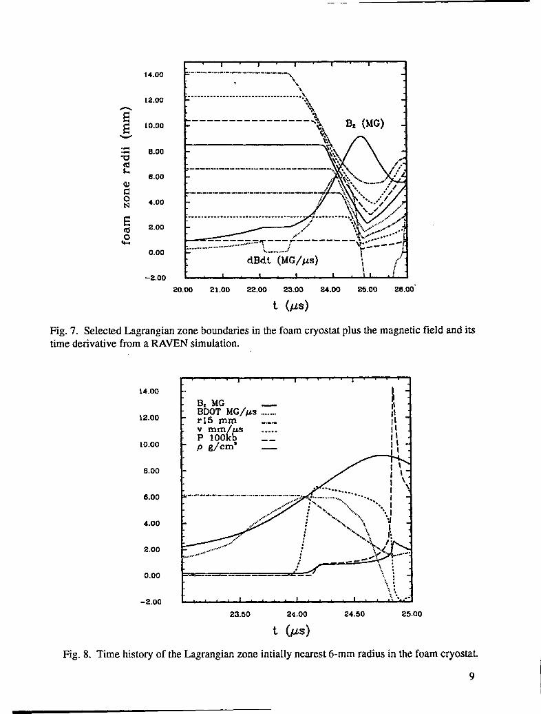
Simulations of the 2:cascade MC-1 weredone with COMP-B and a 0.15 g/cm3 polysty-rene cryostat in preparation for the HTSC experi-ments. Figure 7 shows selected Lagrangian zoneboundaries in the cryostat plotted with thepredicted magnetic field and its derivative. The
1 I 1
10.00
8.00
6.00
4.00
2.00
0.000.00 0.50 1.00 1.50
t = 23.5 /X3 r (cm)
Fig. 5. Profiles through the 2nd and 3rd cascades from RAVEN simulations of the MC-1 driven byCOMP-B at 23.5 w after HE detonation.
7
10.00
8.00
6.00
4.00
2.00
0.00
t I I I 1
,,,0.,0
...”
0.00 0.50 1.00 1.s0
t = 24.6 #S r (cm)
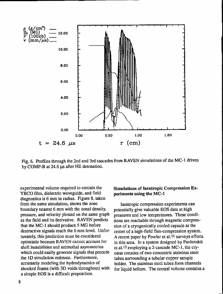
Fig. 6. Profiles through the 2nd and 3rd cascades from RAVEN simulations of the MC-1 drivenby COMP-B at 24.6 w after HE detonation.
experimental volume required to contain theYBCO film, dielectric waveguide, and fielddiagnostics is 6 mm in radius. Figure 8, takenfrom the same simulation, shows the zoneboundary nearest 6 mm with the zonal density,pressure, and velocity plotted on the same graphas the field and its derivative. RAVEN predictsthat the MC- 1 should produce 5 MG beforedestructive signals reach the 6 mm level. Unfor-tunately, this prediction must be consideredoptimistic because RAVEN cannot account forshell instabilities and azimuthal asymmetrieswhich could easily generate signals that precedethe lD simulation estimate. Furthermore,accurately modeling the hydrodynamics ofshocked foams (with 3D voids throughout) witha simple EOS is a difficult proposition.
8
Simulations of Isentropic Compression Ex-periments using the MC-1
Isentropic compression experiments canpotentially give valuable EOS data at highpressures and low temperatures. These condi-tions are reachable through magnetic compres-sion of a cryogenically cooled capsule at thecenter of a high-field flux-compression system.A recent paper by Fowler et al. 11surveys effortsin this area. In a system designed by Pavlovskiiet al. 12employing a 2-cascade MC-1, the cry-ostat consists of two concentric stainless steeltubes surrounding a tubular copper sampleholder. The stainless steel tubes form channelsfor liquid helium. The central volume contains a
14.00
12.00
10.00
0.00
6.00
4.00
2.00
0.00
-2.00
1=.-. -.-, -.-. -.-. -.-. -,----- --,-.-.,“,
L’ “\----” ”---” ”---” ”---” --------- ”--”” -“%
“\“\.
\
●✛☛✎●❝✎☛
✍✍✍✍✍✍ ✍✍✍✍✍✍ ✍✍✍✍ 1
,,,,,,...,..”,.,,.,.. -,,,,..,., -,,-.. . . . . . . . . . . . . . . . . . . . . . . . . . . . . . . . . . . . . . . . .
----- .:..-. T-- +’------ :-------\y_4-. -HL-............ -.,.”,”, ... ...
dBdt (MG\Ps),/-,...d
I { I I I 1 120.00 21.00 22.00 23.00 24.00 25.00 26.00”
Fig. 7. Selected Lagrangian zone boundaries in the foam cryostattime derivative from a RAVEN simulation.
14.00
12.00
10.00
8.00
6.00
4.00
2.00
0.00
-2.00
plus the magnetic field and its
.: i-.%● -1,::.“.~: . . .
4 I 1 !
23.50 24.00 24.50 25.00
t (w)
Fig. 8. Time history of the Lagrangian zone intially nearest 6-mm radius in the foam cryostat
9
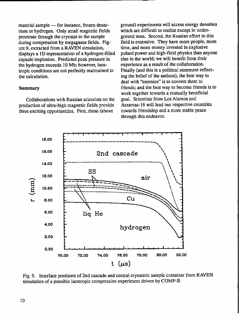
material sample — for instance, frozen deute-rium or hydrogen. Only small magnetic fieldspenetrate through the cryostat to the sampleduring compression by megagauss fields. Fig-ure 9, extracted from a RAVEN simulation,displays a ID representation of a hydrogen-filledcapsule implosion. Predicted peak pressure inthe hydrogen exceeds 10 Mb; however, isen-tropic conditions are not perfectly maintained inthe calculation.
Summary
Collaborations with Russian scientists on theproduction of ultra-high magnetic fields providethree exciting opportunities. First, these (above
ground) experiments will access energy densitieswhich are difficult to realize except in under-ground tests. Second, the Russian effort in thisfield is extensive. They have more people, moretime, and more money invested in explosivepulsed power and high-field physics than anyoneelse in the world; we will benefit from theirexperience as a result of the collaboration.Finally (and this is a political statement reflect-ing the belief of the authors), the best way todeal with “enemies” is to convert them tofriends; and the best way to become friends is towork together towards a mutually beneficialgoal. Scientists from Los Alamos andArzamas- 16 will lead our respective countriestowards friendship and a more stable peacethrough this endeavor.
i.’ I 1 I I I -1
-ii
~
L
Fig. 9.
18.00
16.00
14.00
12.00
10.00
8.00
6.00
4.00
2.00
0.00
1.-.-.-,-,-,-.-,-.-,-,-.-0-, ------------- -------------------
k.\
“. 11- 2nd cascade
-.\.8i. 1
1~.............................s..4....0.0 . ..0.0...! . . . . . . . . . . . . . . . . . . . . . . . . . . . . . . . . . . . . . . . . . . . . . . . .. BOO.,.,.,,,,,... ,
-.-. ~-.
\Ss ;%i%..*.1
\
liq He1.. >\‘\ j+++.\\
hydrogen
. .
70.00 72.00 74.00 76.00 78.00 80.00 82.00
t’ (w)
Interface r)ositions of 2nd cascade and central cryostatic sample container from RAVEN.simulation of a possible isentropic compression experiment driven by COMP-B
10
References 9. Lee, Y. T. and More, R. M., Phys. Fluia%,27,
1.
2.
3.
4.
5.
6.
7.
8.
Pavlovskii, A. I., “Ultra-high Magnetic FieldsCumulation,” in Megagauss Fields andPufsed Power Systems, ed. by Titov, V. M.and Shvetsov, G. A., (Nova Science Publish-ers, Inc., New York, 1990), p. 1.Fowler, C. M., Caird, R. S. and Gain, W. B.,An Introduction to Explosive Magnetic FluxCompression Generators, Los Alamos Scien-tific Laboratory, Los Alamos, NM, UC-34,LA-5890-MS (1975).Pavlovskii, A. I., Karpikov, A. A., Dolotenko,M. I., and Mamyshev, V. L, “Dynamic Char-acteristics Analysis of a Ultra-High MagneticField Cascade Magnetocumulative Generator(MC-1)~’ in Megagauss Fields and PulsedPower Systems, ed. by Tltov, V. M. andShvetsov, G. A., (Nova Science Publishers,Inc., New York, 1990), p. 21.Pavlovskii, A. I., Kolokolchikov, N. P.,Dolotenko, M. I., Bykov, A. I., Karpikov, A.A., Mamyshev, V. I., Spirov G. M., Tatsenko,O. M., Markevtsev, I. N., and Sosnin, P. V.,“Production of 15-MG Magnetic Fields inCascade Ultrahigh Field Generators (MC-1);’in Megagauss Fields and Pulsed PowerSystems, ed. by Thov, V. M. and Shvetsov, G.A., (Nova Science Publishers, Inc., NewYork, 1990), p. 29.Fowler, C M., Gain, W. B. and Caird, R. S.,“Production of Very High Fields by Implo-sion:’ J. AppL Phys., 31,588 (1960).Caird, R. S., Gain, W. B., Thomson, D. B.and Fowler, C. M., “An Explosive-DrivenHigh-Field System for Physics Applications,”J. Appl. Phys., 35,781 (1964).Caird, R. S., Garn, W. B., Thomson, D. B.and Fowler, C. M., “A Cylindrical ExplosiveFlux-Compression System,” in proceedingsof the Conference on Megagauss MagneticField Generation by Explosives and RelatedExperiments, (Frascati, Italy, September21 -23, 1965), p. 101.More, R. M., Lawrence Llvermore NationalLaboratory, Livermore, CA, UCRL-84991(March 1981).
10.
11.
12.
1273 (1984).Pavlovskii, A. I., Bykov, A. I., Dolotenko,M. I., Karpikov, A. A., Kolokolchikov, N. P.,Mamyshev, V. L, and Tatsenko, O. M.,Limiting Value of Reproducible MagneticField in Cascade Generator MC-1 ~’inMegagauss Technology and Pulsed PowerApplications, ed. by Fowler, C. M., Caird,R. S., and Erickson, D. J., (Plenum Press,New York, 1987), p. 159.Fowler, C. M., Caird, R. S., Edeskuty, F. J.,Lund, C. M. and Mills, R. L., “NearlyIsentropic Compression of Materials byLarge Magnetic Fields: A Survey;’ inProceedings of the International Symposiumon Intense Dynamic bading and its E@ects,(Sichuan University Press, Chengdu, China,1992).Pavlovskii, A. 1., Karpikov, A. A.,Mamyshev, V. L, Bykov, A. I., Dolotenko,M. L and Egorov, N. L, “Analysis of MetalTube Compression by Ultra-high MagneticField Pressure in Cascade MC-1 Genera-tors,” in Megagauss Fields and PulsedPower Systems, ed. by Titov, V. M. andShvetsov, G. A., (Nova Science Publishers,Inc., New York, 1990), p. 163.
11
This report has been reproduced directly from thebest available copy.
It is available to DOE and DOE contractors from theOffice of Scientific and Technical Information,P.O. BOX 62,Oak Ridge, TN 37831.Prices are available from(61 5) 576-8401.
It is availabIe to the public from theNational Technical information Service,US Department of Commerce,5285 Port Royal Rd.,
Springfield, VA 22161.

Los AlamosNATIONAL LABORATORY
Los Alarms, New Mexico 87545