Embed Size (px)
Citation preview

Generation of the derivative of out-of-plane displacementsusing conjugate shear and moire interferometry
Krzysztof Patorski
A new method of obtaining the spatial derivative of out-of-plane displacements in a moire interferometrysetup is presented. It is based on the recently developed concept of conjugate lateral shear interferometryapplied to the diffracted beams generated by the specimen grating. The moire fringes produced byoverlapping the two interferograms give the desired information using either the uniform or finite fringedetection method. Simulation experiments using specially prepared transmission-type distorted gratingsare given to verify the principles.
I. Introduction
The moire interferometry method",2 has already be-come a well-established technique for whole-fieldhigh-sensitivity determination of in-plane displace-ments of deformed objects. Two plane wave frontbeams illuminate symmetrically a reflective-type dif-fraction grating fixed to the specimen under study.Due to the matching of incidence angles of impingingbeams with respect to the first-order diffraction angleof the grating, the +1 diffraction order of one illumi-nating beam and the -1 order of the other beam coin-cide in space. They propagate along the specimengrating normal. Because of the specimen loading, thegrating lines are no longer straight and the wave frontsof interfering beams are no longer plane. Their defor-mations due to in-plane displacements are equal inboth diffracted beams but longitudinally reversed.On the other hand, the wave front deformations causedby out-of-plane displacements are of the same valueand sign in both beams. In consequence, they mutual-ly subtract during the interference, and the moire in-terferometry method is said to be insensitive to out-of-plane deformations. The fringes observed giveinformation about the in-plane displacements withhalf a wavelength sensitivity at the theoretical limit.
However, the lack of sensitivity of the moire inter-ferometry method to out-of-plane displacements is en-countered under the approximation of small loads (re-sulting in small values of the out-of-plane objectdeformations). In other words, it is assumed that thepropagation direction of rays forming the interferingdiffraction orders is determined solely by the depar-
The author is with Warsaw Technical University, Institute ofDesign of Precise & Optical Instruments, 8 Chodkiewicza Street, 02-525 Warsaw, Poland.
Received 18 December 1985.0003-6935/86/183146-06$02.00/0.© 1986 Optical Society of America.
ture of specimen grating lines from straightness.However, under higher loads the out-of-plane defor-mations influence the ray propagation directions and,consequently, the in-plane fringe patterns.3 Whenout-of-plane displacements alone are required (forstudying displacement interdependence or to obtainfull information about the deformed body), they can beobtained by special techniques of addition of two dif-fraction orders using the technique of conjugate carrierpatterns.4 '5
For studying the problem of influence of the out-of-plane displacements on the in-plane fringe patterns, itappears useful to have not only the information aboutout-of-plane deformations but also about their firstspatial derivative (representing the slope of the objectsurface).6 The optical method providing this informa-tion was published recently.7 The derivative of out-of-plane displacement is generated in the form of moi-re fringes resulting from the superimposition of twocarrier fringe interferograms recorded in the focusedand defocused planes with respect to the specimengrating surface. The second pattern contains infor-mation about the spatial derivative of the out-of-planedisplacement as well as information present in the firstrecording (about the in-plane displacement only).Overlapping of the two interferograms results in amoire subtractive pattern giving the desired display ofthe derivative of the out-of-plane displacement. Inspite of its simplicity the method possesses some dis-advantages following from recording one of the inter-ferograms in the defocused plane. First, in the case oflarger wave front deformations of interfering diffrac-tion orders, the information recorded in the defocusedplane does not correspond to the wave front phasedistribution on the specimen plane. Second, the in-terferogram quality in the defocused plane is impairedby the Fresnel diffraction patterns of the local imper-fections of the specimen grating and its contamina-tions as well as by the speckling effect. This leads tothe decrease of contrast of the two-beam interferencepattern and, subsequently, to the low contrast of moirefringes.
3146 APPLIED OPTICS / Vol. 25, No. 18 / 15 September 1986
The aim of this paper is to present a new simplemethod that obtains the derivative of out-of-planedisplacement without the disadvantages. It is basedon the recently introduced concept of conjugate lateralshear interferometry.8 The carrier fringe lateral shearinterferograms of each of the two diffraction ordersused in the interferometer are taken separately. Thetwo interferograms have different carrier or shear sign.When they are overlapped the subtractive moirefringes display the sum of derivatives of the wave frontdeformations carried by the two interfering diffractionorders. As a result, the information about the deriva-tive of out-of-plane displacement is obtained since thederivatives of in-plane displacement mutually sub-tract. Either the uniform or finite fringe detectionmode can be used.
The analysis is conducted for one direction only.However, extension to the other two directions1 2 isstraightforward. Simulation experiments using spe-cially prepared transmission-type gratings 7 are de-scribed to verify the principles.
II. Description of the Method
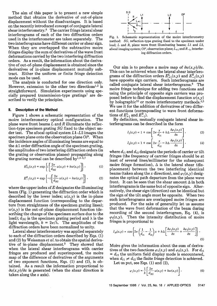
Figure 1 shows a schematic representation of themoire interferometry optical configuration. Theplane wave front beams L and R illuminate the reflec-tion-type specimen grating SG fixed to the object un-der test. The afocal optical system L1-L2 images thespecimen plane onto the observation plane OP. Whenthe incidence angles of illuminating beams are equal tothe L1 order diffraction angle of the specimen grating,the amplitudes of two interfering diffraction orders (inthe grating or observation planes) propagating alongthe grating normal can be described by', 3-5
,7
EL{(xy) = exp 2]} u(x,y) + k.(xy)]} (1)
ER1(xy) = exp [ 2r u(xy) - kw(x Y]} (2)
where the upper index of E designates the illuminatingbeam (Fig. 1) generating the diffraction order which isdescribed by the lower index; u(x,y) is the in-planedisplacement function (corresponding to the depar-ture from straightness of the specimen grating lines);w(x,y) is the out-of-plane displacement function (de-scribing the change of the specimen surface due to theload); dSG is the specimen grating period and X is thelight wavelength, k = 2/X. The amplitudes of thediffraction orders have been normalized to unity.
Lateral shear interferometry was applied separatelyto each of the diffraction orders described by Eqs. (1)and (2) by Weissman et al. to obtain the spatial deriva-tive of in-plane displacement.9 They showed thatwhen the lateral shear interferograms with carrierfringes are produced and superimposed, the moiremap of the difference of derivatives of the argumentsof two exponent functions, Eqs. (1) and (2), is ob-tained. As a result the information proportional toOu(x,y)/Ox is generated (when the shear direction istaken along the x axis).
GI LI ~~~L2 OP
R
+1
Fig. 1. Schematic representation of the moire interferometrymethod: SG, reflection-type grating fixed to the specimen underload; L and R, plane wave front illuminating beams; Ll and L2,afocal imaging system; OP, observation plane; L+1 and R- 1 , interfer-
ing diffraction orders.
Our aim is to produce a moire map of aw(x,y)Iax.This can be achieved when the lateral shear interfero-grams of the diffraction orders Ji 1 (x,y) and E_1 (xy)have opposite sign carriers. Such interferograms arecalled conjugate lateral shear interferograms.8 Themoire fringe technique for adding two functions andusing the principle of opposite sign carriers was pro-posed before to find the displacement function w(x,y)by holographic10 or moire interferometry methods.4 5
We use it for the addition of derivatives of two differ-ent functions (corresponding to wave front deforma-tions of EL1 and ER1 ).
By definition, mutually conjugate lateral shear in-terferograms can be described in the form
I(xy) c 1 + cos F27r x + kA Ol (x,y) 1
12(xy) c 1 + cos 2ir -_ kA Oc (x'y) ,L ( x J(3)
(4)
where dt1 and dt2 designate the periods of carrier or tiltfringes (the frequency of carrrier fringes should be atleast of several lines/millimeter for the subsequentmoire fringe formation), A is the lateral shear (dis-placement) between the two interfering identicalbeams (taken along the x direction), and sol(x,y) desig-nates the optical path departure from the plane wavefront. It can be seen that the shear amount A in bothinterferograms is the same but of opposite sign. Alter-natively, the shear sign (direction) can be identical butthe sign of the tilt angle must be opposite. When twosuch interferograms are overlapped moire fringes areproduced. For the sake of generality let us assumethat the wave front deformation of the beam duringrecording of the second interferogram, Eq. (4), isp2(x,y). Then the intensity distribution of moirefringes is proportional to
cos 1 1 [Oss1l(x,Y) Oso2 (x,y)1IM(X'Y) C 2r T -d x + kA L dx dx JJ"Ydt \dt2 ) ax O9x
(5)
Moire gives the information about the sum of deriva-tives of the two functions (,o(x,y) and ( 2(x,y). For dt1= d 2 the uniform field display mode is encountered,when dt1 X d 2 the finite fringe detection is achieved.
Let us put, see Eqs. (1) and (2),
,I(xy) = [ 27r u(xy) + kw(xy)] (6)
15 September 1986 / Vol. 25, No. 18 / APPLIED OPTICS 3147
S02(XY) = 1 [- 2 u(xy) + kw(xY)] (7)
which corresponds to the formation of mutually conju-gate interferograms of the beams EL, and ER,. FromEq. (5) we obtain
IM(xy) c ( cos2tr + 2 Akw (XY) 1LRdt, dt2 ) ax J (8)
Li L2 O
I G "I~~
* I, Z , Io ,
a)
Therefore, the required information about the firstderivative of the out-of-plane displacement function isobtained.
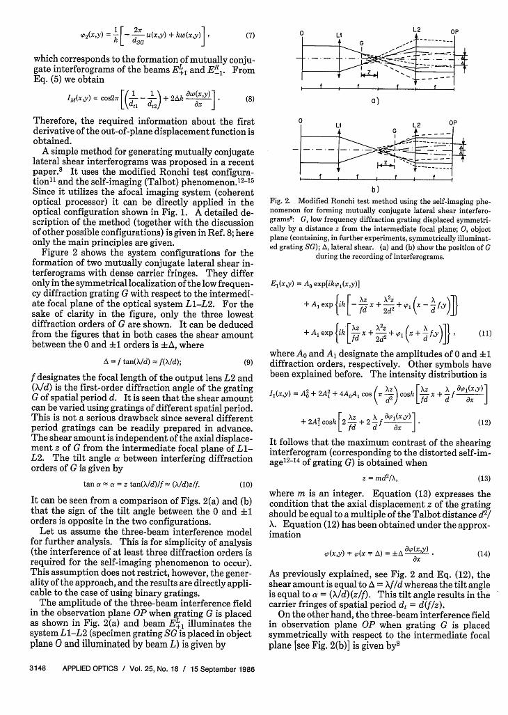
A simple method for generating mutually conjugatelateral shear interferograms was proposed in a recentpaper.8 It uses the modified Ronchi test configura-tion1l and the self-imaging (Talbot) phenomenon.'2 -'5Since it utilizes the afocal imaging system (coherentoptical processor) it can be directly applied in theoptical configuration shown in Fig. 1. A detailed de-scription of the method (together with the discussionof other possible configurations) is given in Ref. 8; hereonly the main principles are given.
Figure 2 shows the system configurations for theformation of two mutually conjugate lateral shear in-terferograms with dense carrier fringes. They differonly in the symmetrical localization of the low frequen-cy diffraction grating G with respect to the intermedi-ate focal plane of the optical system L1-L2. For thesake of clarity in the figure, only the three lowestdiffraction orders of G are shown. It can be deducedfrom the figures that in both cases the shear amountbetween the 0 and 1 orders is +A, where
A = f tan(\/d) f(\Id); (9)
f designates the focal length of the output lens L2 and(X/d) is the first-order diffraction angle of the gratingG of spatial period d. It is seen that the shear amountcan be varied using gratings of different spatial period.This is not a serious drawback since several differentperiod gratings can be readily prepared in advance.The shear amount is independent of the axial displace-ment z of G from the intermediate focal plane of Ll-L2. The tilt angle a between interfering diffractionorders of G is given by
tan a a a = z tan(X/d)/f (d)z/f. (10)
It can be seen from a comparison of Figs. 2(a) and (b)that the sign of the tilt angle between the 0 and i1orders is opposite in the two configurations.
Let us assume the three-beam interference modelfor further analysis. This is for simplicity of analysis(the interference of at least three diffraction orders isrequired for the self-imaging phenomenon to occur).This assumption does not restrict, however, the gener-ality of the approach, and the results are directly appli-cable to the case of using binary gratings.
The amplitude of the three-beam interference fieldin the observation plane OP when grating G is placedas shown in Fig. 2(a) and beam E 1 illuminates thesystem L1-L2 (specimen grating SG is placed in objectplane 0 and illuminated by beam L) is given by
Li L:2
if ~ I I -
I . I I T T
b)Fig. 2. Modified Ronchi test method using the self-imaging phe-nomenon for forming mutually conjugate lateral shear interfero-grams8: G low frequency diffraction grating displaced symmetri-cally by a distance z from the intermediate focal plane; 0, objectplane (containing, in further experiments, symmetrically illuminat-ed grating SG); A, lateral shear. (a) and (b) show the position of G
during the recording of interferograms.
EI(x,y) = AO exp[ikp,(x,y)]
+ Al exp ik [- x +- + ' (- f'
+ Al exp ik [d Xz+ 2 fY ( d )]} (I11)
fd 2d d
where AO and Al designate the amplitudes of 0 and 1diffraction orders, respectively. Other symbols havebeen explained before. The intensity distribution is
II(x,y) = A+ 2A2 + 4AOA1 Cos cosk [Z x0 1 d 2 ~~~fd
A O9o1(xy)1
d O9x J
+ 2Ai2cosk [2X + 2 f OO ],y) (12)
It follows that the maximum contrast of the shearinginterferogram (corresponding to the distorted self-im-age1 2-14 of grating G) is obtained when
z = md2/X, (13)
where m is an integer. Equation (13) expresses thecondition that the axial displacement z of the gratingshould be equal to a multiple of the Talbot distance d2/X. Equation (12) has been obtained under the approx-imation
<O(X,Y) (X F ) = + y (14)Ox
As previously explained, see Fig. 2 and Eq. (12), theshear amount is equal to A = f/d whereas the tilt angleis equal to a = (X/d)(z/f). This tilt angle results in thecarrier fringes of spatial period d = d(f/z).
On the other hand, the three-beam interference fieldin observation plane OP when grating G is placedsymmetrically with respect to the intermediate focalplane [see Fig. 2(b)] is given by8
3148 APPLIED OPTICS / Vol. 25, No. 18 / 15 September 1986

E2 (x,y) = AO exp[ikhp(x,y)]
+ Al exp itk L "Zx - +,Pi(X - f ,YJfd 2d2 d
+ Alexp ik [__' " + 1 (x + f~y)]}. (15)1 d 2d2 ( d)]
However, during the second interferogram formationthe diffraction order ER-(x,y) of the specimen gratingilluminates the system L1-L2 so we have to replace thefunction (pl(xy) in Eq. (15) by the function p2(x,y), seeEqs. (6) and (7). The intensity distribution is calcu-lated by
I2(xy) = A2 + 2A' + 4AA1 cos r ) cosk I-Z x-- f Ix ]2' 0 1 01 d 2 / Lfd d O
+2A cosk [2 dx -2df dx ] (16)
The form of Eq. (16) is the same as Eq. (12) except forthe shear or, alternatively, the carrier sign. Therefore,the interferograms (distorted self-images of G) record-ed for symmetrical localizations of grating G with re-spect to the intermediate focal plane of the system Li-L2 are mutually conjugate. The result of their over-lapping is described by Eq. (8) where dt = dt = dt2 =d(f/z). When the finite fringe display mode ofaw(x,y)/Ax is desired, one of the interferograms shouldbe recorded for a slightly nonsymmetrical position ofgrating G [resulting, however, in the sufficiently highcontrast of the recorded fringe pattern, Eq. (13)].
Let us make some practical remarks about the meth-od. Because we use the self-imaging phenomenon themaximum shear value that can be obtained'5 is of theorder of 2.5 mm. For larger shears the quality of self-images significantly decreases. Moreover, the phasedistribution gradients of the beams used for the inter-ferogram (self-image) formation should be rathersmall. Otherwise, the information about the secondderivative of the phase distribution is simultaneouslypresent; and it impairs the detection of the first deriva-tive information.'3 However, in spite of these limita-tions (common to Talbot interferometry'3- 5) the pro-posed technique, because of its simplicity, seems to beuseful for the application under investigation.
We can easily get rid of the above-mentioned limita-tions for only one localization of grating G shown inFig. 2(a). For this position the spatial filtering opera-tion can be used (the diffraction orders are separatedenough for distances z giving the required spatial fre-quency of carrier fringes of the order of at least severallines per millimeter) allowing the formation of theinterference pattern in the observation plane by twodiffraction orders only (for example, by the 0 and +1diffraction beams). The shear and tilt amounts in thetwo-beam interferogram are governed by the sameEqs. (9) and (10), but now the quality (contrast) of thetwo-beam interference fringes is independent of thewave front deformation and shear value. On the otherhand, spatial filtering is not possible for the other axiallocalization of grating G [see Fig. 2(b)] since the spatial
frequency plane is virtual in this case. The self-sug-gesting idea is to add a second coherent optical proces-sor, to the right of the one shown in Fig. 2, and performthe spatial frequency filtering operation in its frequen-cy plane. Unfortunately, such an imaging system istoo extended for practical use in a moire interferome-try setup. Therefore, we found during the experi-ments that the practical approach is to record the bestcontrast interferogram for some of the distances z ofgrating G as shown in Fig. 2(b) (the interferogramcontrast can be monitored using another diffractiongrating of appropriate period in the observationplane). Next, if the high-contrast self-image cannotbe obtained for the symmetrical position of G [see Fig.2(a)], the two-beam spatial filtering solves the prob-lem.
Finally, it should be noted that the whole analysispresented above considered the perfect alignment ofthe observation system. It requires the coincidence ofthe front focal plane of lens L2 with the back focalplane of Ll (L1 and L2 should form an afocal opticalsystem) and conducting the observation (interfero-gram recording) in the back focal plane of L2. Adetailed discussion of the departure effects from theserequirements is given in Ref. 8. It suffices to say thatin both cases of misalignment the mutual conjugaterelationship between the interferograms is no longerpresent, due to the different shear amounts in bothinterferograms.
It is believed that the proposed method is one of thesimplest (if not the simplest) techniques for formingconjugate lateral shear interferograms. This state-ment follows from a comparison of other interferomet-ric configurations that can be used for the same pur-pose.8 It should be noted that the shearinginterferometry system described by Weissman et al.9for generating the derivative of in-plane displacementcannot be used for formation of mutually conjugatelateral shear interferograms and, consequently, forgenerating w(x,y)/Ox.
Ill. Experimental Work
Some preliminary experiments have been carriedout to verify the principles presented. We have usedan experimental configuration corresponding to anearlier version of the moire interferometry method. Aspecially prepared transmission-type amplitude dif-fraction grating with controlled line deviations hasserved as specimen grating SG instead of the reflectiontype shown in Fig. 1. In such a case the two-beamsymmetrical illumination system has been placed tothe left of grating SG. The grating has been placed atinput plane 0 of the coherent optical processor L1-L2(Fig. 2). Its normal coincides with the optical axis ofL1-L2. The angle between the illuminating beamscan be precisely adjusted to obtain exact spatial coinci-dence of the diffraction orders L+1 and R-1 with theoptical axis.
The way to obtain specimen grating SG with con-trolled line displacements u(x,y) has been described indetail in previous papers.7"16"17 The line deformations
15 September 1986 / Vol. 25, No. 18 / APPLIED OPTICS 3149

Fig. 3. Moire fringes showing the map of simulated in-plane dis-placements. Fringes were formed by superimposing the specimen
grating SG with the master ruling of the same spatial period.
u(x,y) are proportional to the first derivative of wavespherical aberration. Figure 3 shows the moire fringesformed by superimposing our specimen grating withthe master ruling of the same frequency. Moirefringes represent the map of the simulated in-planedisplacement.
As mentioned before, the out-of-plane displacementfield w(x,y) corresponds to the change of specimensurface (its height or profile). The wave fronts ofdiffraction orders L+1 and R-1 are equally influencedby w(xy), see Eqs. (1) and (2). Therefore, to simulatethe method for providing aw(xy)/ax using the experi-mental setup shown in Fig. 2, it is necessary to intro-duce additional identical wave front deformations intothe diffraction orders L+1 and R-1. For example, aphase object could be placed in the close vicinity ofgrating SG. To obtain qualitative as well as quantita-tive verification of the differentiation method pro-posed, the function describing a phase object should beknown. The expected value of aw(x,y)/Ox should becalculated analytically or numerically and then experi-mentally generated.
The first and simplest (but not trivial) choice is tosimulate w(x,y) = 0 by causing the wave fronts of twoilluminating beams L and R to be perfectly plane. Insuch a case, when overlapping the mutually conjugatelateral shear interferograms of the diffraction ordersL+i and R.., uniform intensity distribution should beobtained. In other words, the interferograms de-scribed by Eqs. (12) and (16) of the phase functionsgiven by Eqs. (1) and (2), respectively, are identical.The derivatives of in-plane displacement mutuallysubtract during the patterns overlapping process.
It is important to note that this experiment gives, atthe same time, information about the quality of theafocal system L1-L2. If the aberration is introducedby imaging lenses Li and L2, it is treated as an out-of-plane deformation.
Figure 4 shows the experimental result obtainedwhen overlapping two conjugate interferograms (tak-en at the same symmetrical distances z, Fig. 2) with
Fig. 4. Moire fringes formed by two conjugate lateral shear inter-ferograms with lines mutually inclined for w(xy) = 0.
lines slightly mutually inclined. Straight moirefringes prove the high quality of the imaging optics Li-L2 used. When the lines of two structures are setmutually parallel a uniform intensity distribution isobtained. Therefore, the above result predicted forw(x,y) = 0 is fully verified. Additionally, when record-ing one of the interferograms at a slightly differentvalue of distance z (nonsymmetrical localization ofgrating G with respect to the intermediate focal planeof L1-L2), straight vertical moire fringes are obtainedfor parallel setting of the lines for both interferograms(finite fringe detection mode display).
For the completeness of experimental presentationit is worth mentioning that the derivatives of the in-plane displacement (mutually subtracting in the inter-ferograms overlapping process) correspond in our ex-perimental simulation to the second derivative of thewave front spherical aberration. Their moire mapsgiven by the characteristic elliptical shape fringes wereshown in the previous paper. 7
Next, for the sake of simplicity in the experiment, wedecided to simulate the phase deformation due to theout-of-plane displacement by illuminating specimengrating SG with a spherical wave front instead of aplane one. In this way the wave fronts of interferingorders L+1 and R- are quasi-spherical with the spheri-cal aberration added (the latter caused by the simulat-ed in-plane displacement, see Fig. 3). Figure 5 showsthe moire fringes obtained by overlapping two conju-gate interferograms (taken for the symmetrical local-izations of G, Fig. 2) with lines set mutually parallel.Linear equidistant fringes are obtained, correspondingto the well-known shearing interferogram fringes ofthe spherical wave front. It follows immediately thatfor the finite fringe display mode of aw(x,y)/ax (inter-ferograms recorded for nonsymmetrical distances z ofG), straight equidistant fringes of a different periodfrom the fringes shown in Fig. 5 are obtained. Thisfact was verified experimentally.
As in the previous paper7 the results were verified inour experimental setup by replacing specimen grating
3150 APPLIED OPTICS / Vol. 25, No. 18 / 15 September 1986
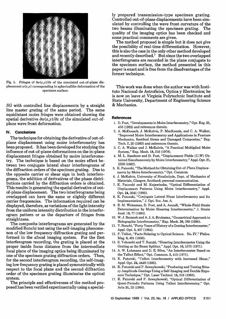
Fig. 5. Fringes of aw(x,y)/Ox of the simulated out-of-plane dis-placement w(xy) corresponding to sphericallike deformation of the
specimen surface.
SG with controlled line displacements by a straightline master grating of the same period. The sameequidistant moire fringes were obtained showing thespatial derivative aw(xy)/ax of the simulated out-of-plane wave front deformation.
IV. Conclusions
The technique for obtaining the derivative of out-of-plane displacement using moire interferometry hasbeen proposed. It has been developed for studying theinfluence of out-of-plane deformations on the in-planedisplacement fringes obtained by moire interferome-try. The technique is based on the moire effect be-tween two conjugate lateral shear interferograms ofthe diffraction orders of the specimen grating. Due tothe opposite carrier or shear sign in both interfero-grams, the addition of derivatives of the phase distri-butions carried by the diffraction orders is obtained.This results in generating the spatial derivative of out-of-plane displacement. The two interferograms beingoverlapped can have the same or slightly differentcarrier frequencies. The information required can bedisplayed, therefore, as variations of the light intensityfrom the uniform intensity distribution in the interfer-ogram pattern or as the departure of fringes fromstraightness.
The composite interferograms are generated by themodified Ronchi test using the self-imaging phenome-non of the low frequency diffraction grating and per-formed in the afocal imaging system. For the firstinterferogram recording, the grating is placed at theproper inside focus distance from the intermediatefocal plane of the imaging optics being illuminated byone of the specimen grating diffraction orders. Then,for the second interferogram recording, the self-imag-ing low frequency grating is placed symmetrically withrespect to the focal plane and the second diffractionorder of the specimen grating illuminates the opticalsystem.
The principle and effectiveness of the method pro-posed has been verified experimentally using a special-
ly prepared transmission-type specimen grating.Controlled out-of-plane displacements have been sim-ulated by controlling the wave front curvature of thetwo beams illuminating the specimen grating. Thequality of the imaging optics has been checked andsome practical comments are given.
The method proposed is simple but it does not givethe possibility of real-time differentiation. However,this is also the case in the only other method developedand recently described.7 But since the two overlappedinterferograms are recorded in the plane conjugate tothe specimen surface, the method presented in thispaper is exact and is free from the disadvantages of theformer technique.
This work was done when the author was with Insti-tuto Nacional de Astrofisica, Optica y Electronica; heis now on leave at Virginia Polytechnic Institute andState University, Department of Engineering Science& Mechanics.
References
1. D. Post, "Developments in Moire Interferometry," Opt. Eng. 21,458 (1982) and references therein.
2. A. McDonach, J. McKelvie, P. MacKenzie, and C. A. Walker,"Improved Moire Interferometry and Applications in FractureMechanics, Residual Stress and Damaged Composites," Exp.Tech. 7, 20 (1983) and references therein.
3. C. A. Walker and J. McKelvie, "A Practical Multiplied MoireSystem," Exp. Mech. 18, 316 (1978).
4. M. L. Basehore and D. Post, "Displacement Fields (UW) Ob-tained Simultaneously by Moire Interferometry," Appl. Opt. 21,2558 (1982).
5. K. Patorski, "The Method for Obtaining Out-of-Plane Displace-ments by Moire Interferometry," Opt. Commun.
6. J. McKelvie, University of Strathclyde, Dept. of Mechanics ofMaterials, Glasgow, Scotland; personal communication.
7. K. Patorski and M. Kujawinska, "Optical Differentiation ofDisplacement Patterns Using Moire Interferometry," Appl.Opt. 24, 3041 (1985).
8. K. Patorski, "Conjugate Lateral Shear Interferometry and ItsImplementation," J. Opt. Soc. Am. A.
9. E. M. Weissman, D. Post, and A. Asundi, "Whole-Field StrainDetermination by Moire Shearing Interferometry," J. StrainAnal. 19, 77 (1984).
10. W. J. Beranek and A. J. A. Bruinsma, "Geometrical Approach toHolographic Interferometry," Exp. Mech. 20, 289 (1980).
11. V. Ronchi, "Forty Years of History of a Grating Interferometer,"Appl. Opt. 3,437 (1964).
12. F. Talbot, "Facts Relating to Optical Science. No. IV," Philos.Mag. 9, 401 (1836).
13. S. Yokozeki and T. Suzuki, "Shearing Interferometer Using theGrating as the Beam Splitter," Appl. Opt. 10, 1575 (1971).
14. A. W. Lohmann and D. E. Silva, "An Interferometer Based onthe Talbot Effect," Opt. Commun. 2, 413 (1971).
15. K. Patorski, "Talbot Interferometry with Increased Shear,"Appl. Opt. 24,4448 (1985).
16. K. Patorski and P. Szwaykowski, "Producing and Testing Bina-ry Amplitude Gratings Using a Self-Imaging and Double Expo-sure Technique," Opt. Laser Technol. 15, 316 (1983).
17. K. Patorski and P. Szwaykowski, "Optical Differentiation ofQuasi-Periodic Patterns Using Talbot Interferometry," Opt.Acta 31, 23 (1984).
15 September 1986 / Vol. 25, No. 18 / APPLIED OPTICS 3151


![APPROVED - Virginia Tech...of these advantages, moire technique is very unique and significantly advanced [21]. Moire interferometry is extremely powerful for shear strain measurement](https://img.pdfslide.us/doc/110x75/60c116ee1f993f1dd564c5ee/approved-virginia-tech-of-these-advantages-moire-technique-is-very-unique.jpg)