Embed Size (px)
Citation preview
Generating Topological Informa*ionfrom a "Bucket of Facets"
Stephen J. RockMichael J. Wozny
Rensselaer Design Research CenterRensselaer Polytechnic Institute
Troy, New York 12180
AbstractThe STL de facto data exchange standard for Solid Freefonn F*brication represents
CAD models as a collection of unordered triangular planar facels. No topologicalconnectivity infonnation is provided; hence the term "bucket of facet~." Such topologicalinformation can, however, be quite useful for performing model v~lidity checking andspeeding subsequent processing operations such as model slicing. lfhis paper discussesmodel topology and how to derive it given a collection of unordered tri,ngular facets whichrepresent a valid model.
1 IntroductionComputer Aided Design (CAD) model data is frequently pas~ed to various Solid
Freeform Fabrication processes using the STL polygonal facet repre~entation [1]. Facetmodels represent solid objects by spatial boundaries which are defin~d by a set of planarfaces. This is a special case of the more general Boundary Represent,tion which does notrequire object boundaries be planar [2]. In general, the term facet isl used to denote anyconstrained polygonal planar region being used to define a model bottndary; however, inthe Solid Freeform Fabrication (SFF) community the term facet is typlically understood tomean triangular facet. Representing models using triangular facets ha~ both good and badpoints [3]. Facets do provide a "greatest common denominator" geo~etrical form for dataexchange between many CAD systems and SFF processes. Non-C~D scalar field data,such as that from CT imaging, can also be used to generate facet mqdels [4]. However,facet models are generally only an approximation of mathematically prepise CAD models.
Precise CAD models must be tessellated, where defining P'lodel surfaces aresubdivided into planar facets, to create polygonal facet models [5]. lAs model precisiondemands become more stringent, the number of facets required to adeq*ately approximate amodel will increase. Model tessellation should yield a set of facets wpich define a closedregion representing the material boundary of a part. Unfortunately, m~y commercial CADsystem model tessellators are not robust, and sets of facets which qo not define closedregions result. This missing facet problem is particularly prevalent wh~re surfaces intersectin the original CAD models. A set of facets which, when assembled,lforms a solid objectwith holes in its surface is incomplete and is termed an invalid mqdel. In addition tomissing facets, other causes of model invalidity exist. They include errqrs due to numericalround-off, missing data, altered data, and sometimes the presencle of extraneous orredundant data.
The de facto industry standard STL model representation defin~s models as a set oftriangular facets [1]. Unfortunately, these facets are stored independeptly, as if each facetwere created and tossed into a bucket with no particular ordering and }vithout informationrelating a given facet to any other facets in the bucket. Since many ~AD systems fail togenerate valid facet model tessellations, it is necessary to perform moqel validity checkingbefore subsequent processing operations are undertaken. Given onlyl the data in an STLfile, performing model validity checking is computationally expensiive. Attempting to
© 1992 RPI Rensselaer Design Research Center. All Rights Reserved.
251
determine the relationships, or topology, between model facets from the "bucket of facets"is the first step in performing validity checking. The resulting topological information isimportant for use in subsequent processing operations such as model repair, model slicing,and finally during the scan conversion operation.
2 TopologyTopology describes the connectivity relationships between various geometric
entities [2]. A facet can reference the three edges which bound it. Each edge can referencethe two vertices which define it. Topological connectivity relationships are not limited toindividual facets. For instance, a facet can reference the three facets which share edgeswith it. An edge can reference not only the two vertices which define it but also the twofacets which share it. Vertex points can contain connectivity information to all edges orfaces which share it. Such references are all examples of topological connectivityinformation.
It is important to consider two topological classes of boundary representationmodels: manifold (two-manifold) and non-manifold. A two-manifold is defined as a twodimensional, connected surface where each point on the surface has a neighborhoodtopologically equivalent to an open disk [6]. In a two-manifold, every edge in the model isshared by two and only two facets. This is the case for most facet models where only thefacets representing a part's spatial boundaries exist. One side of a facet is directed towardpart material, and the other is directed away from it. The spatial boundaries of a facetmodel are expected to have a distinct "inside" and "outside" which is consistent across allfacets defining the model boundary; such a model is termed orientable [2]. Non-manifoldconditions occur where, for example, two distinct enclosing volumes share one facet or aset of facets as a common boundary [7]. In this case, the shared facet no longer has a clear"inside" or "outside". Both sides of the facet are surrounded by part material. Thistypically occurs when facets representing multiple solids which are tangent along someboundary are not properly delimited as belonging to individual solids in an STL fIle.
3 Benefits of Topological InformationThe STL format represents facet models with nearly the minimal information
necessary to define a solid object. Each facet, along with its normal, is specified explicitlyand no topological connectivity information is provided. This "bucket of facets" approachto model representation has many limitations, both with respect to ensuring valid modelsand subsequent processing.3.1 Validity Checking
When no topological information is provided, model validity checking involvescomputationally expensive searching operations. If model topology were available, validitychecking would be a much simpler and efficient operation.3.2 Model Repair
When invalid models are encountered, topological information is useful forattempting to repair the models. Such information makes it readily apparent when greaterthan two facets share a single model edge. In the case of model holes, it is important toknow how the facets surrounding a hole are connected and this too can be easilydetermined given topological information.3.3 Subsequent Processing
Facet model slicing performance can also benefit from topological informationwhich makes it possible to march from facet to neighboring facet performing simpleedge/plane intersection calculations [8]. This same topological information can be passed tosubsequent processing phases, such as scan conversion, which occur after slicing.
252
3.4 Model RepresentationFinally, model topology generation capability has facilitated the development of a
richer facet model representation format [9]. Storing topological information with a facetmodel, although increasing the information content of the model, reduces the volume ofdata required when compared to an equivalent model represented in STL format. The netresult is a more robust representation with less data.
4 Topology Reconstruction ConceptsReconstructing model topology given a "bucket of facets" is basically a searching
operation. Entity relationships must be found by searching the unordered model data.These relationships, or topology, must then be stored for later use. The conceptual stepsfor producing such topology will now be discussed; however, implementation details, suchas the searching algorithms or structures used, will be dealt with separately after thetopology reconstruction concepts are understood.4.1 Vertex Merging
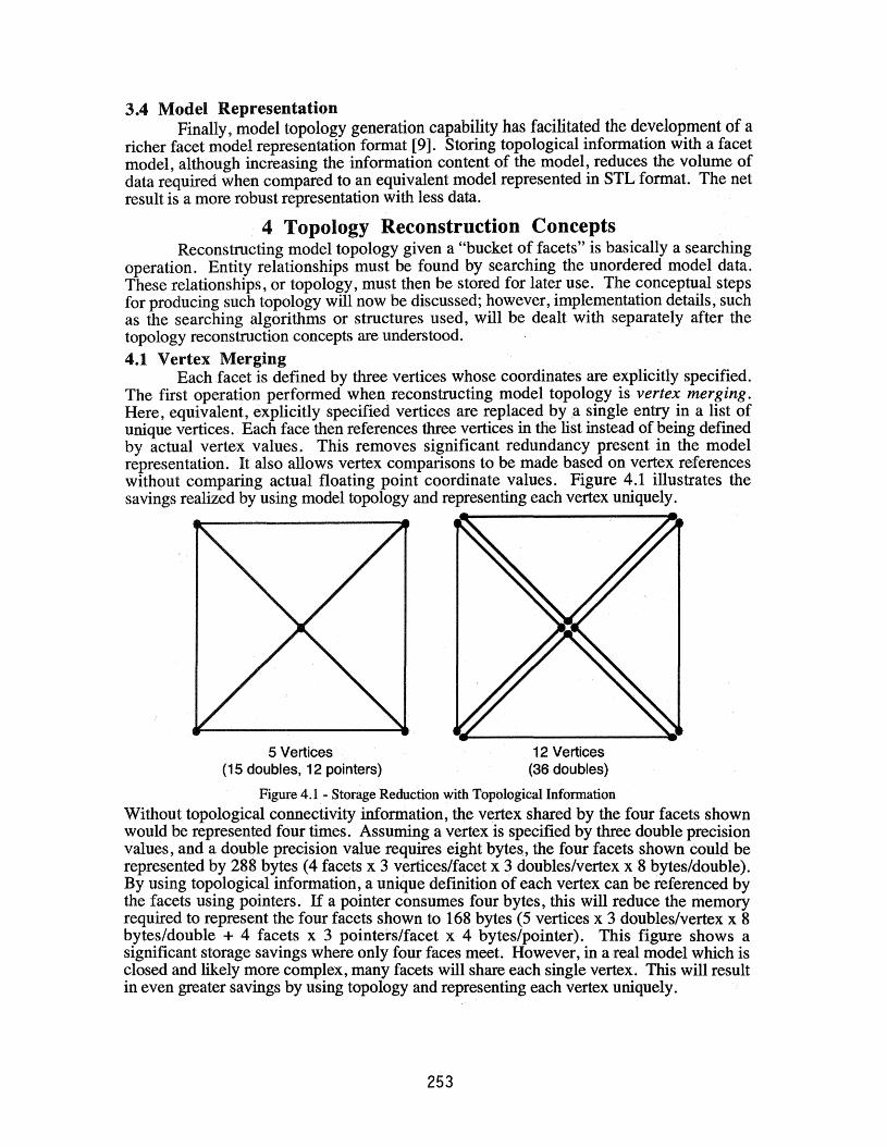
Each facet is defined by three vertices whose coordinates are explicitly specified.The first operation performed when reconstructing model topology is vertex merging.Here, equivalent, explicitly specified vertices .are replaced bya single entry in a list ofunique vertices. Each face then references three vertices in the list instead of being definedby actual vertex values. This removes significant redundancy present in the modelrepresentation. It also allows vertex comparisons to be made based on vertex referenceswithout comparing actual floating point coordinate values. Figure 4.1 illustrates thesavings realized by using model topology and representing each vertex uniquely.
5 Vertices(15 doubles, 12 pointers)
12 Vertices(36 doubles)
Figure 4.1 - Storage Reduction with Topological Information
Without topological connectivity information, the vertex shared by the four facets shownwould be represented four times. Assuming a vertex is specified by three double precisionvalues, and a double precision value requires eight byte&, the four facets shown coulg berepresented by 288 bytes (4 facets x 3 vertices/facet x 3 doubles/vertex x8 bytes/double).By using topological information, a unique definition of each vertex can be referenced bythe facets using pointers. If a pointer consumes four bytes, this will reduce the memoryrequired to represent the four facets shown to 168 bytes (5 vertices x 3· doubles/vertex x 8bytes/double + 4 facets x 3 pointers/facet x 4 bytes/pointer). This figure shows asignificant storage savings where only four faces meet. However, in a real model which isclosed and likely more complex, many facets will share each single vertex. This will resultin even greater savings by using topology and representing each vertex uniquely.
253
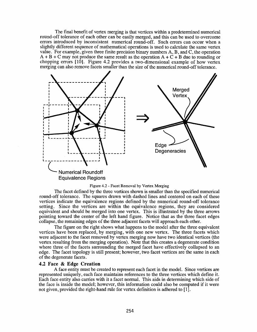
The final benefit of vertex merging is that vertices within a predetermined numericalround-off tolerance of each other can be easily merged, and this can be used to overcomeerrors introduced by inconsistent numerical round-off. Such errors can occur when aslightly different sequence of mathematical operations is used to calculate the same vertexvalue. For example, given three finite precision binary numbers A, B, and C, the operationA + B + C may not produce the same result as the operation A + C + B due to rounding orchopping errors [10]. Figure 4.2 provides a two-dimensional example of how vertexmerging can also remove facets smaller than the size of the numerical round-off tolerance.
IL I-_
IIIIL _
------------- ----~
C Numerical RoundoffEquivalence Regions
Figure 4.2 - Facet Removal by Vertex Merging
The facet defined by the three vertices shown is smaller than the specified numericalround-off tolerance. The squares drawn with dashed lines and centered on each of thesevertices indicate the equivalence regions defined by the numerical round-off tolerancesetting. Since the vertices are within the equivalence regions, they are consideredequivalent and should be merged into one vertex. This is illustrated by the three arrowspointing toward the center of the left hand figure. Notice that as the three facet edgescollapse, the remaining edges of the three adjacent facets will approach each other.
The figure on the right shows what happens to the model after the three equivalentvertices have been replaced, by merging, with one new vertex. The three facets whichwere adjacent to the facet removed by vertex merging now have two identical vertices (thevertex resulting from the merging operation). Note that this creates a degenerate conditionwhere three of the facets surrounding the merged facet have effectively collapsed to anedge. The facet topology is still present; however, two facet vertices are the same in eachof the degenerate facets.
4.2 Face & Edge CreationA face entity must be created to represent each facet in the model. Since vertices are
represented uniquely, each face maintains references to the three vertices which define it.Each face entity also carries with it a facet normal. This aids in determining which side ofthe face is inside the model; however, this information could also be computed if it werenot given, provided the right-hand rule for vertex definition is adhered to [1].
254
Similarly, it is possible to create edge entities to represent model edges. Each edgecan reference the two vertices which define it and the two faces which share it. Edgeinformation is not provided by STL format files, but it can have utility when slicing facetmodels and can be represented using alternative rue formats [3]. The following section willshow that it is appropriate to wait until face relationships have been determined beforecreating model edges.4.3 Determining Face & Edge Relationships
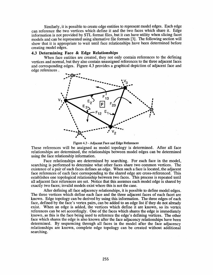
When face entities are created, they not only contain references to the definingvertices and normal, but they also contain unassigned references to the three adjacent facesand corresponding edges. Figure 4.3 provides a graphical depiction of adjacent face andedge references .
Figure 4.3 - Adjacent Face and Edge References
These references will be assigned as model topology is determined. After all facerelationships are determined, the relationships between model edges can be determinedusing the face relationship information.
Face relationships are determined by searching. For each face in the model,searching is performed to determine what other faces share two common vertices. Theexistence of a pair of such faces defines an edge. When such a face is located, the adjacentface references of each face corresponding to the shared edge are cross-referenced. Thisestablishes one topological relationship between two faces. This process is repeated untilall adjacent face references are set. Notice that this assumes each model edge is shared byexactly two faces; invalid models exist where this is not the case.
After defining all face adjacency relationships, it is possible to define model edges.The three vertices which define each face and the. three adjacent faces of each facet areknown. Edge topology can be derived by using this information. The three edges of eachface, defined by the face's vertex pairs, can be added to an edge list if they do not alreadyexist. When an edge is added, the vertices which define it are known, so its vertexreferences can be set accordingly. One of the faces which shares the edge is immediatelyknown, as this is the face being used to reference the edge's defining vertices. The. otherface which shares the edge is also known after the face adjacency relationships have beendetermined. By •• sequencing through all faces in the model after the face adjacencyrelationships are known, complete edge topology can be created without additionalsearching.
255

5 Data Structures & AlgorithmsThe fundamental operations used to reconstruct model topology have been
discussed, but few operational details were provided. If brute force approaches to vertexmerging and adjacent facet searching are used, computational cost will quickly becomeprohibitive as model complexity increases. Consequently, care must be taken to ensure thedata structures and algorithms employed facilitate efficient searching.
Facets are read sequentially from a data file with no particular ordering. Each timedata representing a facet is read, a face entity is created. Three vertex entities, each of whichmay already exist or need to be created, are referenced by each face entity. A linear list,although a poor structure for sorting and searching, can be used to store the face entitiesbecause they are not searched directly. Vertex entities must, before they are created, betested to ensure an equivalent vertex does not already exist. If it does, this equivalentvertex should be referenced by the newly instantiated face entity instead of creating a newvertex entity and referencing it. A searching operation is required to perform thisequivalence testing, and it is repeated for each model vertex. Repeatedly searching, andmaintaining in sorted order, a linear list of vertex entities is a costly proposition. Analternative to the linear list data structure should be used.5.1 The AVL Tree for Vertex Merging
With the goal of vertex merging in mind, a linear list is clearly an unacceptablesolution for storing the unique vertices. Each time a vertex entity is added, the complete listwould have to be sorted and/or searched. Recall that one requirement for vertex merging isthat all equivalent vertices be merged. This suggests that for a vertex entity to be added,there must be no existing equivalent vertices. Consequently, a range of vertex values in theneighborhood of the search key must be tested. This makes a hash table an unattractivestorage structure. A sorted array could be used, but because vertex data is continuallybeing added as each model facet is read, repeated insertions into the array and the blockmoves which result make this an unattractive solution. A binary search tree could be used;however, the input data ordering is unknown. In the degenerate case, this could beequivalent in performance to searching a linear list of vertex values, and this isunacceptable.
A balanced binary search tree, termed an AVL search tree, overcomes theselimitations [11]. It never degenerates to the equivalent performance of searching a linearlist because its balance is maintained as each element is inserted in it. It also meets therequirements for being able to traverse through the data and efficiently allow rangesearching, which is used to determine equivalence within a set numerical round-offtolerance after an initial search value if located.
As each vertex defining a face is read, it is added to an AVL search tree if anequivalent vertex does not already exist in the tree. If the vertex is added, thecorresponding vertex reference for the face being added is set to this vertex element in theAVL tree. If an equivalent face exists, the corresponding vertex reference for the facebeing added is set to the equivalent vertex already in the AVL tree and the vertex data readis discarded. The AVL search tree data structure works well to provide an efficientequivalence detection mechanism for vertices being added. After vertex merging iscompleted, face adjacency relationships must be determined.5.2 Searching for Face Adjacencies
Face comparisons are performed in an attempt to locate face adjacencies. Recall thatface adjacencies are determined for each face in the model by sequentially stepping througha list of model faces, searching for adjacent faces, and cross-connecting references whenadjacencies are located. A linear list of faces provides the ability to sequentially processfaces, but it is clearly not the solution for an efficient searching structure.
256
The structure imposed to effect efficient adjacency searching is simply a list of facepointers attached to each vertex in the model. As new vertices are created or existingvertices are referenced by a given face, the reference value of this face is added to a list offace references for each vertex which defines the face. Consequently, each vertex knowsof every face which references it after all model faces have been read from the data file.Searching for adjacencies is greatly simplified using this structure. Instead of searchingevery face in the model for a face which shares two vertices with a test face, now only thefaces contained in the face lists corresponding to the three vertices defining a test face needto be searched.
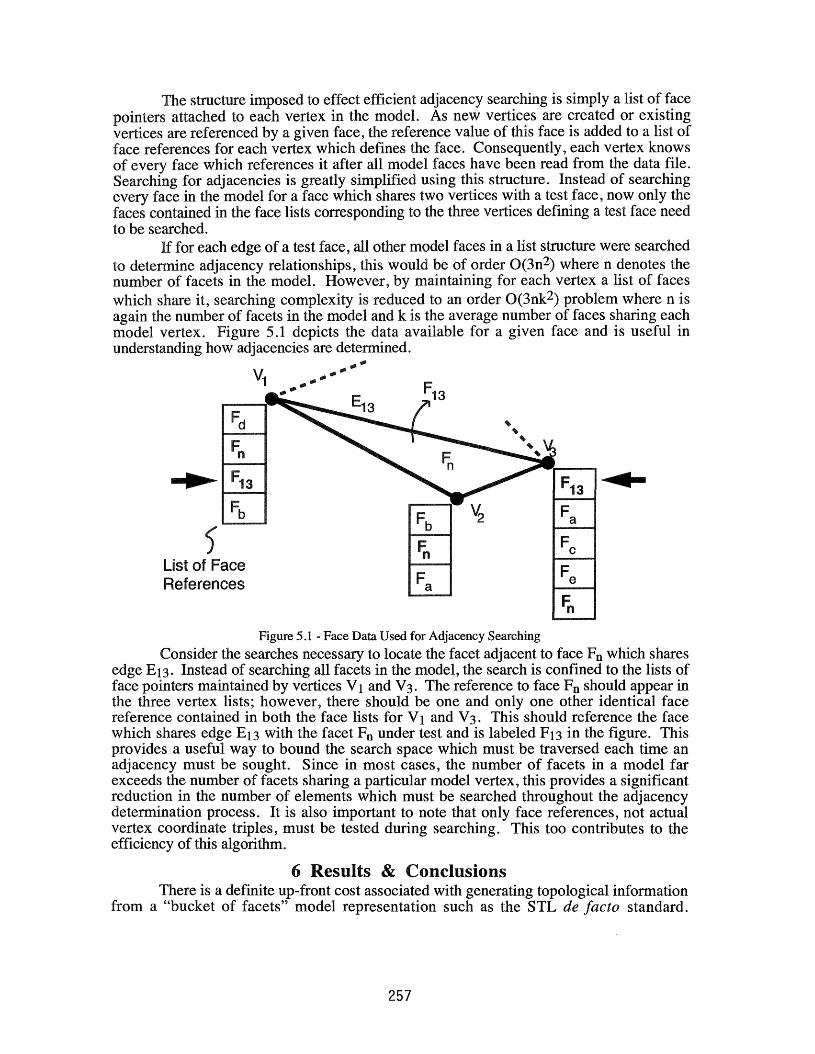
for each edge of a test face, all other model faces in a list structure were searchedto determine adjacency relationships, this would be of order O(3n2) where n denotes thenumber of facets in the model. However, by maintaining for each vertex a list of faceswhich share it, searching complexity is reduced to an order O(3nk2) problem where n isagain the number of facets in the model and k is the average number of faces sharing eachmodel vertex. Figure 5.1 depicts the data available for a given face and is useful inunderstanding how adjacencies are determined.
.",."'"
V1
.",..",..",."",.",..",."",
F13 .......-..Fb
Fa
) Fn FeList of FaceReferences Fa Fe
Fn
Figure 5.1 - Face Data Used for Adjacency Searching
Consider the searches necessary to locate the facet adjacent to face Fn which sharesedge £13. Instead of searching all facets in the model, the search is confined to the lists offace pointers maintained by vertices V1 and V3. The reference to face Fn should appear inthe three vertex lists; however, there should be one and only one other identical facereference contained in both the face lists for V1 and V3. This should reference the facewhich shares edge £13 with the facet Fn under test and is labeled F13 in the figure. Thisprovides a useful way to bound the search space which must be traversed each time anadjacency must be sought. Since in most cases, the number of facets in a model farexceeds the number of facets sharing a particular model vertex, this provides a significantreduction in the number of elements which must be searched throughout the adjacencydetermination process. It is also important to note that only face references, not actualvertex coordinate triples, must be tested during searching. This too contributes to theefficiency of this algorithm.
6 Results & ConclusionsThere is a definite up-front cost associated with generating topological information
from a "bucket of facets" model representation such as the STL de facto standard.
257
pre-processing adds information which can be used tomodel processing operations.
reference lists for each vertex increases memory""...r"T~,r"IO..", a very necessary performance increase. By using an
an 0(3n2) algorithm, processing for model topologya model with approximately 82,500 facets, 8.6
:r..... "..,,_lJ ..."" ....."-'Jl.Jl""" were to generate its topology when the bruteHowever, the 0(3nk2) algorithm performed thesame machine. It is important to note that these
ASCII file. Preliminary evaluation of an""""'0""""''' binary format STL files suggests that the contrast
tree approaches is even larger because parse timeCPU minute figure cited above[12].
only a "bucket of facets", can be computationally........"',..."","' .... .", is taken. Appropriate data structures and algorithms
gexlen:ltlcm an profitable exercise. An important lesson......._ .... 1"'>......... - ... increase in storage requirements can effect a
is important for successful model processing, andendeavor. Unfortunately, the SFF community's STL defacto
models does not support the definition of model topology ....'Ol",r\1I"II,C>'h........ t-l:)rl from an unordered "bucket of facets" provided by the STL
significant searching through model facet data which ispart models. The approach presented in this paper
magnitude performance improvement when contrast to ageIlenlUCln approach.
..'VI""'V ...,Jj>., '''''' information should be generated during model tessellation1-'''''' ' '' , ..... by a CAD system. This would not only prevent the need to
it would also make data transfer more robust and concise. The RPI... '-" ~" ""Jl.Jl ..VJlJllJ , a significant redundancy reduction while increasing the informationcontent a by utilizing topological information [9]. While facet models may fade asthe primary representation for future SFF data exchange, topological information and someof the lessons learned from this work will remain important for higher-order geometrical
as patch models.
Acknowledgmentsresc~an~n was supported by NSF Grant DDM-8914212 as a subcontract
Texas Solid Freeform Fabrication program, the New York Statethe Office of Naval Research, and other grants of the
(RDRC) Industrial Associates Program. Any""....,Jl..""........ lJJl. ...., ...JllJ, or recommendations expressed in this publication are
not necessarily reflect the views of the National ScienceCenter for Advanced Technology, the Office of Naval
....U ........ lJlWl .......... sponsors.to thank Dick Aubin, Pratt & Whitney (a division of United
a number of industrial STL models. A special thanks tou ......·UUJl"" comments and ideas on early drafts of this paper, and to
helpful comments.
258

References1. "Stereolithography Interface Specification," 3D Systems, Inc., June 1988.2. Michael E. Mortenson, Geometric Modeling, John Wiley & Sons, Inc., 1985.3. Stephen J. Rock, "Solid Freeform Fabrication and CAD System Interfacing," M.S.
Thesis, Rensselaer Polytechnic Institute, Troy, NY, Dec. 1991.4. James V. Miller, "On GDM's: Geometrically Deformed Models for the Extraction of
Closed Shapes from Volume Data," M.S. Thesis, Rensselaer Polytechnic Institute,Dec. 1990.
5. Donald Hearn and M. Pauline Baker, Computer Graphics, Prentice-Hall, Inc., 1986.6. Kevin Weiler, "Edge-Based Data Structures for Solid Modeling in Curved-Surface
Environments," IEEE Computer Graphics and Applications, Vol. 5, Num. 1, pp. 2140, Jan. 1985.
7. Kevin Weiler, "The Radial Edge Structure: A Topological representation for NonManifold Geometric Boundary Modeling," in: Geometric Modeling for CADApplications, M. J. Wozny, H. W. McLaughlin, J. L. Encarnacao (eds.), NorthHolland, pp. 3-36, 1988.
8. Stephen J. Rock and Michael J. Wozny, "Utilizing Topological Information toIncrease Scan Vector Generation Efficiency," in: Solid Freeform FabricationSymposium Proceedings, H.L. Marcus, J. J. Beaman, J.W. Barlow, D.L. Bourell,and R.H. Crawford (eds.), The University of Texas at Austin, Aug. 1991.
9. Stephen J. Rock and Michael J. Wozny, "A Flexible File Format for Solid FreeformFabrication," in: Solid Freeform Fabrication Symposium Proceedings, H.L. Marcus,J. J. Beaman, J.W. Barlow, D.L. Bourell, and R.H. Crawford (eds.), The Universityof Texas at Austin, Aug. 1991.
10. Kendall Atkinson, Elementary Numerical Analysis, John Wiley and Sons, Inc., 1985.11. Daniel F. Stubbs and Neil W. Webre, Data Structures with Abstract Data Types and
Pascal, Brooks/Cole Publishing Company, 1989.12. Jan Helge B¢hn, Personal Communication, June 30, 1992.
259