Embed Size (px)
Citation preview


Generalized MPLS Introduction and Deployment Session BRKMPL-3010
Santiago Álvarez
Distinguished Engineer

© 2013 Cisco and/or its affiliates. All rights reserved. BRKMPL-3010 – [email protected] Cisco Public
Agenda
Motivation
Technology Overview
Dynamic Optical Path Setup
Diverse Optical Path Setup
Deployment Considerations
Summary
3
© 2013 Cisco and/or its affiliates. All rights reserved. BRKMPL-3010 – [email protected] Cisco Public
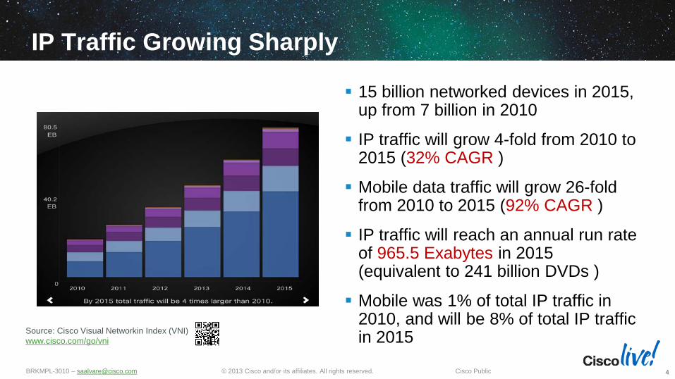
IP Traffic Growing Sharply
15 billion networked devices in 2015, up from 7 billion in 2010
IP traffic will grow 4-fold from 2010 to 2015 (32% CAGR )
Mobile data traffic will grow 26-fold from 2010 to 2015 (92% CAGR )
IP traffic will reach an annual run rate of 965.5 Exabytes in 2015 (equivalent to 241 billion DVDs )
Mobile was 1% of total IP traffic in 2010, and will be 8% of total IP traffic in 2015
4
Source: Cisco Visual Networkin Index (VNI) www.cisco.com/go/vni

© 2013 Cisco and/or its affiliates. All rights reserved. BRKMPL-3010 – [email protected] Cisco Public
Convergence Requires Network Agility Eliminating Rigid, Costly, Separate Networks
5
Data Center A
Data Center B
Data Center C Transport Network
IP Engineering requests path from transport team
1
Transport Planning researches capacity for best path
2
Transport Operations provisions network path at each node
3
IP Operations provisions VPN service
4
1 Week 3 Weeks 4 Weeks 2 Weeks
IP Network
Divided Networks
Up to 2 Months

© 2013 Cisco and/or its affiliates. All rights reserved. BRKMPL-3010 – [email protected] Cisco Public
Elastic Network: Agile and Efficient nLight Technology
6
Existing 10G Fiber, Amplifiers, Dispersion Compensation Modules, …
CRS ASR 9000
Core
Up to 36% TCO Savings and over 90% Fiber CAPEX Reuse
Edge Reuse over 90% of Fiber Infrastructure CAPEX
Reduce Provisioning Time from Months to Minutes
Recycle Capacity by Eliminating Over Provisioning
• nLight Control Plane – built on GMPLS • nLight Silicon for Coherent 100G+, 3000km w/o Regeneration • nLight ROADMs: Zero-Touch Optical
© 2013 Cisco and/or its affiliates. All rights reserved. BRKMPL-3010 – [email protected] Cisco Public
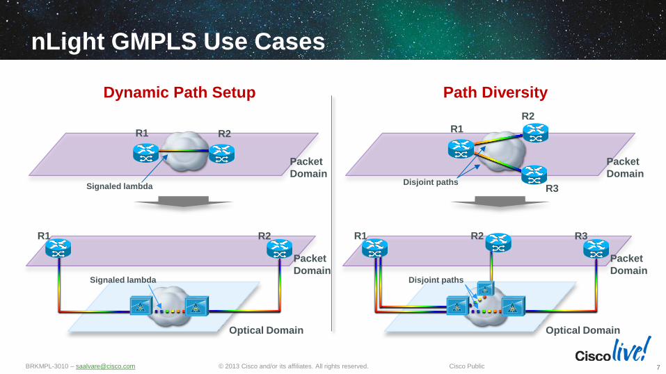
nLight GMPLS Use Cases
7
Packet Domain
Optical Domain
R1
Packet Domain
R2 R3
R1 R2
R3
Path Diversity
Disjoint paths
Disjoint paths
Dynamic Path Setup
Packet Domain
Optical Domain
R1
Packet Domain
R2
R1 R2
Signaled lambda
Signaled lambda

Technology Overview
© 2013 Cisco and/or its affiliates. All rights reserved. BRKMPL-3010 – [email protected] Cisco Public
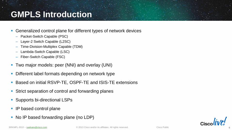
GMPLS Introduction
Generalized control plane for different types of network devices – Packet-Switch Capable (PSC) – Layer-2 Switch Capable (L2SC) – Time-Division-Multiplex Capable (TDM) – Lambda-Switch Capable (LSC) – Fiber-Switch Capable (FSC)
Two major models: peer (NNI) and overlay (UNI)
Different label formats depending on network type
Based on initial RSVP-TE, OSPF-TE and ISIS-TE extensions
Strict separation of control and forwarding planes
Supports bi-directional LSPs
IP based control plane
No IP based forwarding plane (no LDP)
9
© 2013 Cisco and/or its affiliates. All rights reserved. BRKMPL-3010 – [email protected] Cisco Public
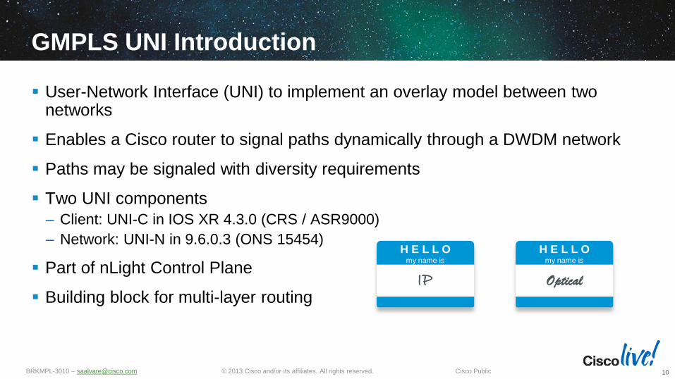
GMPLS UNI Introduction
User-Network Interface (UNI) to implement an overlay model between two networks
Enables a Cisco router to signal paths dynamically through a DWDM network
Paths may be signaled with diversity requirements
Two UNI components – Client: UNI-C in IOS XR 4.3.0 (CRS / ASR9000) – Network: UNI-N in 9.6.0.3 (ONS 15454)
Part of nLight Control Plane
Building block for multi-layer routing
10
H E L L O my name is
I IPP
H E L L O my name is
Optical
© 2013 Cisco and/or its affiliates. All rights reserved. BRKMPL-3010 – [email protected] Cisco Public
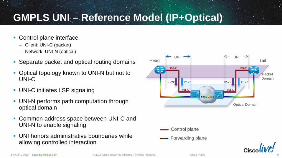
GMPLS UNI – Reference Model (IP+Optical)
Control plane interface – Client: UNI-C (packet) – Network: UNI-N (optical)
Separate packet and optical routing domains
Optical topology known to UNI-N but not to UNI-C
UNI-C initiates LSP signaling
UNI-N performs path computation through optical domain
Common address space between UNI-C and UNI-N to enable signaling
UNI honors administrative boundaries while allowing controlled interaction
11
UNI-C UNI-C
UNI-N UNI-N
Packet Domain
Optical Domain
UNI UNI Head Tail
RSVP RSVP RSVP RSVP
Forwarding plane
Control plane
© 2013 Cisco and/or its affiliates. All rights reserved. BRKMPL-3010 – [email protected] Cisco Public
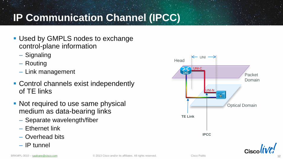
IP Communication Channel (IPCC)
Used by GMPLS nodes to exchange control-plane information – Signaling – Routing – Link management
Control channels exist independently of TE links
Not required to use same physical medium as data-bearing links – Separate wavelength/fiber – Ethernet link – Overhead bits – IP tunnel
12
UNI-C
UNI-N
Packet Domain
Optical Domain
UNI Head
TE Link
IPCC

© 2013 Cisco and/or its affiliates. All rights reserved. BRKMPL-3010 – [email protected] Cisco Public
Link Management Protocol (LMP)
Performs two core functions – Control channel management – Link property correlation
GMPLS nodes require an LMP adjacency formed over one or more bi-directional control channels
Runs over UDP with mechanisms for reliable message transmission
Includes mechanisms for LMP neighbor discovery
Most messages exchanged over control channel
Can also provide link connectivity verification and fault management
13

Dynamic Optical Path Setup
© 2013 Cisco and/or its affiliates. All rights reserved. BRKMPL-3010 – [email protected] Cisco Public
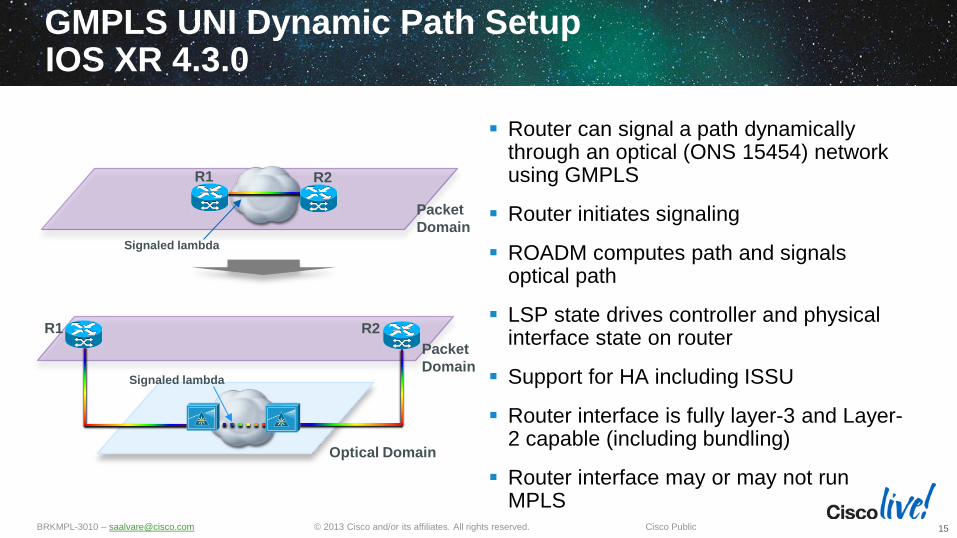
GMPLS UNI Dynamic Path Setup IOS XR 4.3.0
Router can signal a path dynamically through an optical (ONS 15454) network using GMPLS
Router initiates signaling
ROADM computes path and signals optical path
LSP state drives controller and physical interface state on router
Support for HA including ISSU
Router interface is fully layer-3 and Layer-2 capable (including bundling)
Router interface may or may not run MPLS
15
Packet Domain
Optical Domain
R1
Packet Domain
R2
R1 R2
Signaled lambda
Signaled lambda

© 2013 Cisco and/or its affiliates. All rights reserved. BRKMPL-3010 – [email protected] Cisco Public
Path Computation and Signaling
UNI-C (Head) – Initiates signaling (default lambda) – No explicit path (ERO) defined / signaled – Signaling initiated towards remote UNI-C (optical loopback or optical link address) – Bi-directional path (upstream and downstream labels)
UNI-N – Arrival of PATH message without ERO triggers path computation to destination across
optical domain – Establishment of optical path (trail) required for UNI signaling to proceed
16

© 2013 Cisco and/or its affiliates. All rights reserved. BRKMPL-3010 – [email protected] Cisco Public
Signaling –Path Setup
Optical impairment check
UNI PATH (upstream label = lambda)
UNI PATH (upstream label = lambda)
UNI-C UNI-C UNI-N UNI-N
UNI PATH (upstream label = default lambda)
1
2
3 Trail Downstream PATH
Trail Upstream PATH
Trail Downstream RESV
Trail Upstream RESV
UNI PATH ERROR (upstream label = lambda)
UNI PATH (upstream label = lambda)
6 Trail established
8
Tunnel established
UNI RESV (Label = lambda)
UNI RESV (Label = lambda)
UNI RESV (Label = lambda)
7
Tunnel established
5 Trail established
Optical impairment check
Per-hop optical parameters
4
Head initiates tunnel
signaling
Optical path computation, trail signaling initiated
17
© 2013 Cisco and/or its affiliates. All rights reserved. BRKMPL-3010 – [email protected] Cisco Public
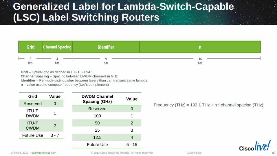
Generalized Label for Lambda-Switch-Capable (LSC) Label Switching Routers
18
Identifier Grid Channel Spacing n
Grid Value Reserved 0
ITU-T DWDM 1
ITU-T CWDM 2
Future Use 3 - 7
3 bits
4 bits
9 bits
16 bits
DWDM Channel Spacing (GHz) Value
Reserved 0 100 1 50 2 25 3
12.5 4 Future Use 5 - 15
Frequency (THz) = 193.1 THz + n * channel spacing (THz)
Grid – Optical grid as defined in ITU-T G.694.1 Channel Spacing – Spacing between DWDM channels in GHz Identifier – Per-node distinguisher between lasers than can transmit same lambda n – value used to compute frequency (two’s complement)
© 2013 Cisco and/or its affiliates. All rights reserved. BRKMPL-3010 – [email protected] Cisco Public
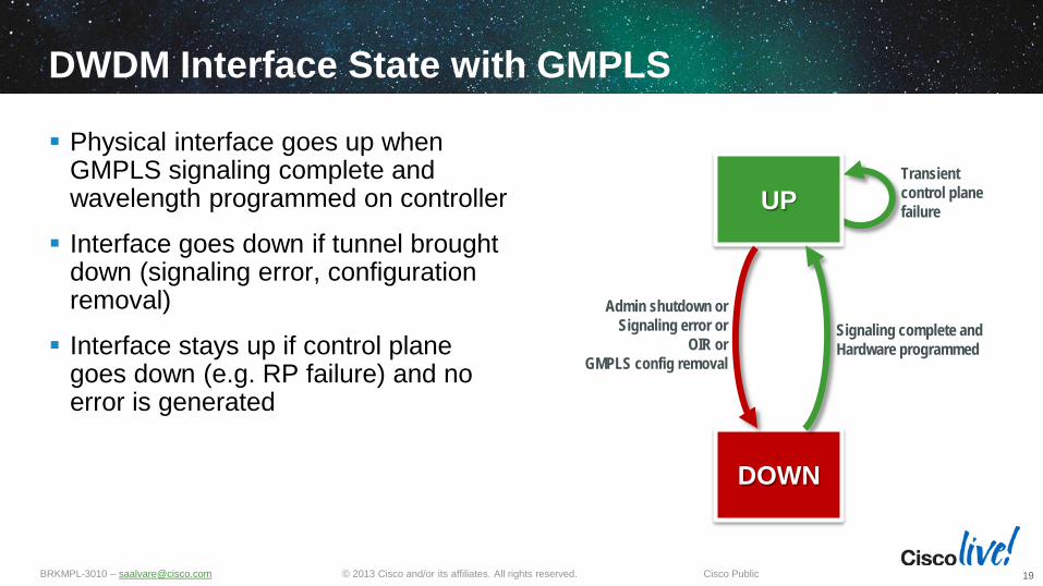
DWDM Interface State with GMPLS
Physical interface goes up when GMPLS signaling complete and wavelength programmed on controller
Interface goes down if tunnel brought down (signaling error, configuration removal)
Interface stays up if control plane goes down (e.g. RP failure) and no error is generated
19
UP
DOWN
Admin shutdown or Signaling error or
OIR or GMPLS config removal
Signaling complete and Hardware programmed
Transient control plane failure
© 2013 Cisco and/or its affiliates. All rights reserved. BRKMPL-3010 – [email protected] Cisco Public
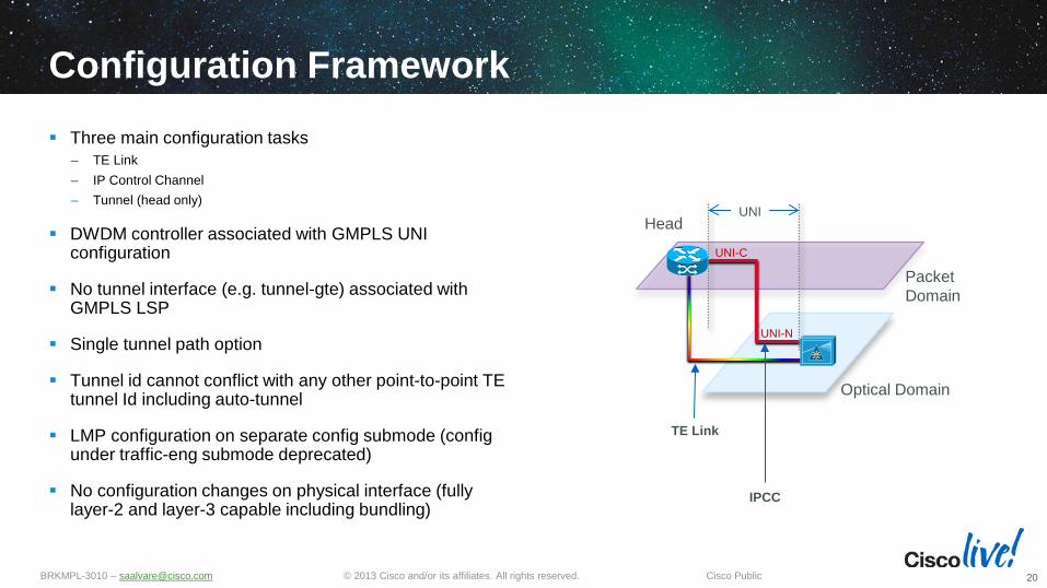
Configuration Framework Three main configuration tasks
– TE Link – IP Control Channel – Tunnel (head only)
DWDM controller associated with GMPLS UNI configuration
No tunnel interface (e.g. tunnel-gte) associated with GMPLS LSP
Single tunnel path option
Tunnel id cannot conflict with any other point-to-point TE tunnel Id including auto-tunnel
LMP configuration on separate config submode (config under traffic-eng submode deprecated)
No configuration changes on physical interface (fully layer-2 and layer-3 capable including bundling)
20
UNI-C
UNI-N
Packet Domain
Optical Domain
UNI Head
TE Link
IPCC

© 2013 Cisco and/or its affiliates. All rights reserved. BRKMPL-3010 – [email protected] Cisco Public
Head-end Base Configuration
21
interface Loopback0 description PACKET ROUTER ID ipv4 address 10.0.255.1 255.255.255.255 ! interface Loopback1 description OPTICAL ROUTER ID ipv4 address 172.16.255.11 255.255.255.255 ! interface GigabitEthernet0/0/0/8 description OPTICAL CONTROL PLANE ipv4 address 172.16.1.0 255.255.255.254 ! interface HundredGigE0/1/0/0 description LOOK MOM: I WAS SIGNALED VIA GMPLS ipv4 address 10.0.0.0 255.255.255.254 ! controller dwdm0/1/0/0 admin-state in-service ! router static address-family ipv4 unicast 172.16.255.1/32 172.16.1.1 ! !
Optical router id must be reachable
UNI-C UNI-C
UNI-N UNI-N
Packet Domain
Optical Domain
UNI UNI Head Tail
RSVP RSVP RSVP RSVP rid:172.16.255.1 rid: 172.16.255.2
rid:172.16.255.11 rid: 172.16.255.22 rid: 10.0.255.1 rid: 10.0.255.2
Packet routing Domain: 10/8
Optical routing Domain: 172.16/16 (IPCC) 172.17/16 (Link Id)
link-id: 172.17.1.0
link-id: 172.17.1.1
172.16.1.0
172.16.1.1
link-id: 172.17.2.0
link-id: 172.17.2.1
172.16.2.0
172.16.2.1

© 2013 Cisco and/or its affiliates. All rights reserved. BRKMPL-3010 – [email protected] Cisco Public
Head-end Base Configuration (cont.)
22
mpls traffic-eng gmpls optical-uni controller dwdm0/1/0/0 tunnel-properties tunnel-id 100 destination ipv4 unicast 172.17.2.0 path-option 10 no-ero lockdown ! ! ! ! end
lmp gmpls optical-uni controller dwdm0/1/0/0 neighbor HEAD-UNI-N neighbor link-id ipv4 unicast 172.17.1.1 neighbor interface-id unnumbered 11 link-id ipv4 unicast 172.17.1.0 ! neighbor HEAD-UNI-N ipcc routed router-id ipv4 unicast 172.16.255.1 ! router-id ipv4 unicast 172.16.255.11 ! ! rsvp controller dwdm0/1/0/0 signalling refresh out-of-band interval 86400 ! !
Static Control Channel Adjacency (routable)
Optical Router Id (routable)
GMPLS Tunnel Configuration
Static TE Link Properties
(non routable)
Daily RSVP State Refresh
© 2013 Cisco and/or its affiliates. All rights reserved. BRKMPL-3010 – [email protected] Cisco Public
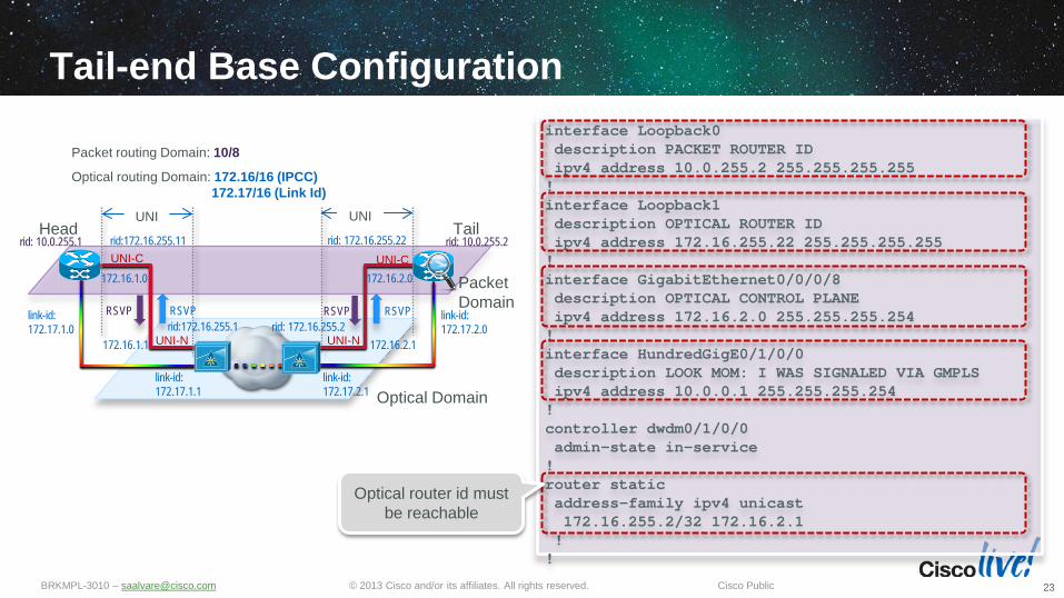
Tail-end Base Configuration
23
UNI-C UNI-C
UNI-N UNI-N
Packet Domain
Optical Domain
UNI UNI Head Tail
RSVP RSVP RSVP RSVP rid:172.16.255.1 rid: 172.16.255.2
rid:172.16.255.11 rid: 172.16.255.22 rid: 10.0.255.1 rid: 10.0.255.2
Packet routing Domain: 10/8
Optical routing Domain: 172.16/16 (IPCC) 172.17/16 (Link Id)
link-id: 172.17.1.0
link-id: 172.17.1.1
172.16.1.0
172.16.1.1
link-id: 172.17.2.0
link-id: 172.17.2.1
172.16.2.0
172.16.2.1
interface Loopback0 description PACKET ROUTER ID ipv4 address 10.0.255.2 255.255.255.255 ! interface Loopback1 description OPTICAL ROUTER ID ipv4 address 172.16.255.22 255.255.255.255 ! interface GigabitEthernet0/0/0/8 description OPTICAL CONTROL PLANE ipv4 address 172.16.2.0 255.255.255.254 ! interface HundredGigE0/1/0/0 description LOOK MOM: I WAS SIGNALED VIA GMPLS ipv4 address 10.0.0.1 255.255.255.254 ! controller dwdm0/1/0/0 admin-state in-service ! router static address-family ipv4 unicast 172.16.255.2/32 172.16.2.1 ! !
Optical router id must be reachable

© 2013 Cisco and/or its affiliates. All rights reserved. BRKMPL-3010 – [email protected] Cisco Public
Tail-end Base Configuration (cont.)
24
mpls traffic-eng gmpls optical-uni controller dwdm0/1/0/0 ! ! ! end
lmp gmpls optical-uni controller dwdm0/1/0/0 neighbor TAIL-UNI-N neighbor link-id ipv4 unicast 172.17.2.1 neighbor interface-id unnumbered 22 link-id ipv4 unicast 172.17.2.0 ! neighbor TAIL-UNI-N ipcc routed router-id ipv4 unicast 172.16.255.2 ! router-id ipv4 unicast 172.16.255.22 ! ! rsvp controller dwdm0/1/0/0 signalling refresh out-of-band interval 86400 ! !
Daily RSVP State Refresh
No GMPLS Tunnel Configuration
(tunnel still bidirectional)
Static Control Channel Adjacency (routable)
Optical Router Id (routable)
Static TE Link Properties
(non routable)

Diverse Optical Path Setup
© 2013 Cisco and/or its affiliates. All rights reserved. BRKMPL-3010 – [email protected] Cisco Public
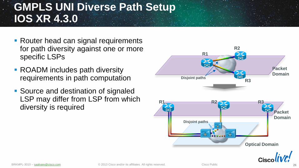
GMPLS UNI Diverse Path Setup IOS XR 4.3.0
Router head can signal requirements for path diversity against one or more specific LSPs
ROADM includes path diversity requirements in path computation
Source and destination of signaled LSP may differ from LSP from which diversity is required
26
Packet Domain
Optical Domain
R1
Packet Domain
R2 R3
R1 R2
R3 Disjoint paths
Disjoint paths
© 2013 Cisco and/or its affiliates. All rights reserved. BRKMPL-3010 – [email protected] Cisco Public
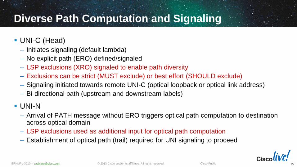
Diverse Path Computation and Signaling
UNI-C (Head) – Initiates signaling (default lambda) – No explicit path (ERO) defined/signaled – LSP exclusions (XRO) signaled to enable path diversity – Exclusions can be strict (MUST exclude) or best effort (SHOULD exclude) – Signaling initiated towards remote UNI-C (optical loopback or optical link address) – Bi-directional path (upstream and downstream labels)
UNI-N – Arrival of PATH message without ERO triggers optical path computation to destination
across optical domain – LSP exclusions used as additional input for optical path computation – Establishment of optical path (trail) required for UNI signaling to proceed
27

© 2013 Cisco and/or its affiliates. All rights reserved. BRKMPL-3010 – [email protected] Cisco Public
Signaling – Diverse Path Setup
28
UNI PATH (upstream label = lambda)
UNI PATH (upstream label = lambda)
UNI-C UNI-C UNI-N UNI-N
UNI PATH (upstream label = default lambda)
1
Head initiates tunnel
signaling including
LSP exclusion
2
Optical path computation subject to LSP exclusions,
trail signaling initiated
3 Trail Downstream PATH
Trail Upstream PATH
Trail Downstream RESV
Trail Upstream RESV
UNI PATH ERROR (upstream label = lambda)
UNI PATH (upstream label = lambda)
6 Trail established
8
Tunnel established
UNI RESV (Label = lambda)
UNI RESV (Label = lambda)
UNI RESV (Label = lambda)
7
Tunnel established
5 Trail established
Per-hop optical parameters
4
Optical impairment check
Optical impairment check
© 2013 Cisco and/or its affiliates. All rights reserved. BRKMPL-3010 – [email protected] Cisco Public
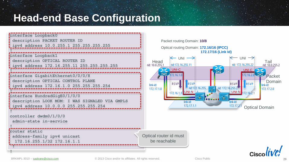
Head-end Base Configuration
29
interface Loopback0 description PACKET ROUTER ID ipv4 address 10.0.255.1 255.255.255.255 ! interface Loopback1 description OPTICAL ROUTER ID ipv4 address 172.16.255.11 255.255.255.255 ! interface GigabitEthernet0/0/0/8 description OPTICAL CONTROL PLANE ipv4 address 172.16.1.0 255.255.255.254 ! interface HundredGigE0/1/0/0 description LOOK MOM: I WAS SIGNALED VIA GMPLS ipv4 address 10.0.0.0 255.255.255.254 ! controller dwdm0/1/0/0 admin-state in-service ! router static address-family ipv4 unicast 172.16.255.1/32 172.16.1.1 ! !
Optical router id must be reachable
UNI-C UNI-C
UNI-N UNI-N
Packet Domain
Optical Domain
UNI UNI Head Tail
RSVP RSVP RSVP RSVP rid:172.16.255.
1 rid: 172.16.255.2
rid:172.16.255.11 rid: 172.16.255.22 rid: 10.0.255.1 rid: 10.0.255.2
Packet routing Domain: 10/8
Optical routing Domain: 172.16/16 (IPCC) 172.17/16 (Link Id)
link-id: 172.17.1.0
link-id: 172.17.1.1
172.16.1.0
172.16.1.1
link-id: 172.17.2.0
link-id: 172.17.2.1
172.16.2.0
172.16.2.1
© 2013 Cisco and/or its affiliates. All rights reserved. BRKMPL-3010 – [email protected] Cisco Public
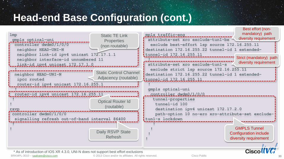
Head-end Base Configuration (cont.)
30
mpls traffic-eng attribute-set xro exclude-tun1-be exclude best-effort lsp source 172.16.255.11 destination 172.16.255.22 tunnel-id 1 extended-tunnel-id 172.16.255.11 ! attribute-set xro exclude-tun1-s exclude strict lsp source 172.16.255.11 destination 172.16.255.22 tunnel-id 1 extended-tunnel-id 172.16.255.11 ! gmpls optical-uni controller dwdm0/1/0/0 tunnel-properties tunnel-id 100 destination ipv4 unicast 172.17.2.0 path-option 10 no-ero xro-attribute-set exclude-tun1-s lockdown ! ! ! !
lmp gmpls optical-uni controller dwdm0/1/0/0 neighbor HEAD-UNI-N neighbor link-id ipv4 unicast 172.17.1.1 neighbor interface-id unnumbered 11 link-id ipv4 unicast 172.17.1.0 ! neighbor HEAD-UNI-N ipcc routed router-id ipv4 unicast 172.16.255.1 ! router-id ipv4 unicast 172.16.255.11 ! ! rsvp controller dwdm0/1/0/0 signalling refresh out-of-band interval 86400 ! !
Static Control Channel Adjacency (routable)
Optical Router Id (routable)
GMPLS Tunnel Configuration include diversity requirement
Static TE Link Properties
(non routable)
Daily RSVP State Refresh
Best effort (non-mandatory) path
diversity requirement
Strict (mandatory) path diversity requirement
* As of introduction of IOS XR 4.3.0, UNI-N does not support best effort exclusions

Deployment Considerations

© 2013 Cisco and/or its affiliates. All rights reserved. BRKMPL-3010 – [email protected] Cisco Public
Concurrent Static and Dynamic (Signaled) Lambda Configuration
Controller can be configured with static in addition to GMPLS UNI signaling
If signaling successful, signaled lambda takes precedence over static lambda
Adding GMPLS UNI configuration to an operational controller with a static lambda expected to initiate signaling for existing lambda and not disrupt traffic
32

© 2013 Cisco and/or its affiliates. All rights reserved. BRKMPL-3010 – [email protected] Cisco Public
MPLS-TE and GMPLS Co-existence (IOS XR 4.3.0)
Router would have two RSVP neighbors if packet network runs MPLS-TE on DWDM interface, – RSVP neighbor over physical interface
for MPLS TE signaling – RSVP neighbor over controller for
GMPLS signaling
Separate RSVP refresh timers – High frequency for MPLS TE signaling – Low frequency for GMPLS signaling
(lowest 232 ms or ~1.6 months)
33
Packet Domain
Optical Domain
R1 R2
Signaled lambda
RSVP
RSVP

© 2013 Cisco and/or its affiliates. All rights reserved. BRKMPL-3010 – [email protected] Cisco Public
GMPLS vs. MPLS TE (IOS XR 4.3.0)
34
Header GMPLS LSP TE LSP Path Bidirectional (upstream+downstream) Unidirectional (Downstream)
End Point Roles One head + one tail
One head + one tail (P2P) or multiple tails (P2MP)
Label DWDM Wavelength Label (32 bits) in control plane Circuit in forwarding plane
Packet label (20-bit) in control plane Packet label (20-bit part of shim header) in forwarding plane
Path Computation UNI-N Head End Signaling Initiation Head End Head End
Physical Interface Relationship 1:1 (fixed) N:1 (flexible)
Signaling Routing Objects No ERO
Optional XRO RRO (optional)
ERO RRO (optional)
Signaling Label Objects
Generalized Label Request (PATH) Upstream Label (PATH)
Generalized Label (RESV) Acceptable Label Set (PATH)
Label Request (PATH) Label (RESV)
Signaled Bandwidth Fixed CT0 (controller rate) Configurable CT0/CT1 Reservation Style Fixed Filter (FF) Shared Explicit (SE)
Tunnel Id Static Static | Dynamic (auto-tunnel) Tunnel Destination UNI-C optical router id | UNI-C optical link address Router id | Interface id
Protection N/A FRR | Path protection Preemption N/A Hard | Soft
Re-optimization N/A Hitless
© 2013 Cisco and/or its affiliates. All rights reserved. BRKMPL-3010 – [email protected] Cisco Public
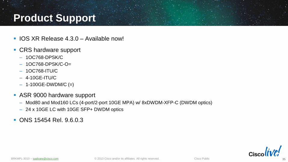
Product Support
IOS XR Release 4.3.0 – Available now!
CRS hardware support – 1OC768-DPSK/C – 1OC768-DPSK/C-O= – 1OC768-ITU/C – 4-10GE-ITU/C – 1-100GE-DWDM/C (=)
ASR 9000 hardware support – Mod80 and Mod160 LCs (4-port/2-port 10GE MPA) w/ 8xDWDM-XFP-C (DWDM optics) – 24 x 10GE LC with 10GE SFP+ DWDM optics
ONS 15454 Rel. 9.6.0.3
35

Summary

© 2013 Cisco and/or its affiliates. All rights reserved. BRKMPL-3010 – [email protected] Cisco Public
Summary
Explosive traffic growth and changing traffic patterns driving requirements for agile IP+Optical integration
Cisco nLight uses GMPLS as control plane to enable an elastic network infrastructure
Cisco GMPLS UNI implementation allows controlled interaction between packet and optical domains to – Dynamically set up paths between routers across a DWDM network – Signaling and computation of diverse optical paths
Solution available in Cisco CRS, ASR 9000 and ONS 15454 products today
37

© 2013 Cisco and/or its affiliates. All rights reserved. BRKMPL-3010 – [email protected] Cisco Public
MPLS Content at Cisco Live US 2013 BRKMPL-1100 - Introduction to MPLS BRKMPL-2100 -Deploying MPLS Traffic Engineering BRKMPL-2101 - Deploying MPLS-based Layer 2 Virtual Private Networks BRKMPL-2102 - Deploying MPLS-based IP VPNs BRKMPL-2108 - Designing MPLS in Next Generation Data Center: A Case Study BRKMPL-2109 - MPLS Solutions for Cloud Networking BRKMPL-2333 - E-VPN & PBB-EVPN: the Next Generation of MPLS-based L2VPN BRKMPL-3010 - Generalized MPLS - Introduction and Deployment BRKMPL-3101 - Advanced Topics and Future Directions in MPLS LTRMPL-2102 - Enterprise Network Virtualization using IP and MPLS Technologies: Introduction LTRMPL-3100 - Unified MPLS Lab LTRMPL-3102 - Enterprise Network Virtualization using IP and MPLS Technologies: Advanced PNLSPG-3999 - Transport Evolution in SP Core Networks TECMPL-3100 - Unified MPLS - An architecture for Advanced IP NGN Scale TECMPL-3200 - SDN WAN Orchestration in MPLS and Segment Routing Networks
38

© 2013 Cisco and/or its affiliates. All rights reserved. BRKMPL-3010 – [email protected] Cisco Public
Maximize your Cisco Live experience with your free Cisco Live 365 account. Download session PDFs, view sessions on-demand and participate in live activities throughout the year. Click the Enter Cisco Live 365 button in your Cisco Live portal to log in.
Complete Your Online Session Evaluation
Give us your feedback and you could win fabulous prizes. Winners announced daily. Receive 20 Cisco Daily Challenge
points for each session evaluation you complete. Complete your session evaluation
online now through either the mobile app or internet kiosk stations.
39


![[MPLS Configuration Guide] - D-Link Academyacademy.dlink.com/temp/exam_Issue/230/MPLS Configuration Guide… · MPLS Configuration Guide Multiprotocol Label Switching (MPLS) MPLS](https://img.pdfslide.us/doc/110x75/5a815ac47f8b9ada388cfeea/mpls-configuration-guide-d-link-configuration-guidempls-configuration-guide.jpg)